design and fatigue analysis of bicycle crank-lever
TRANSCRIPT

International Research Journal of Engineering and Technology (IRJET) e-ISSN: 2395-0056
Volume: 08 Issue: 06 | June 2021 www.irjet.net p-ISSN: 2395-0072
2021, IRJET | Impact Factor value: 7.529 | ISO 9001:2008 Certified Journal | Page 2906
Design and Fatigue Analysis of Bicycle Crank-Lever
Shivakumar RV1, Mohammad Zaki2, Ritic Jain3, Devendra Kumar4, Ranjit Singh5
1Assistant Professor, JSS Academy of Technical Education Noida, Uttar Pradesh, India 2,3,4,5Student, Department of Mechanical Engineering, JSS Academy of Technical Education Noida,
Uttar Pradesh, India ----------------------------------------------------------------------***---------------------------------------------------------------------
Abstract - Design of Bicycle operated by Crank-Lever is new technique employed in replacement of chain drive power transmission. In Crank – Chain system there is a loss of power delivery, lesser efficiency, and maximum efforts are required to apply force on pedal for movement. The present work Bicycle consists of oscillating pedal lever, connecting lever, freewheel disc, freewheel sprocket, bearings, and mounting plates. Power transferred through oscillating reciprocation of pedals forced by the driver legs, allows the rotation of wheel. This project delineates stresses induced in the lever and disc based on force analysis and Finite element analysis to know the cost-effective material and life. The maximum stress and fatigue life were estimated, using the Finite Element Analysis (FEA). Analysis result contour plots are also validated by various checks. The main purpose of this project is to reduce human effort required for cycling with minimize foot numbness and tingling. Key Words: Crank-lever-pedal, Free wheel disc, Free wheel sprocket, Bearings, and Mounting plates.
1. INTRODUCTION
Movement is the essence of life. The principle of levers. By keeping ‘effort’ arm small one can move the ‘load’ through a larger distance. Moreover, every development performed on the bicycle has to take into account the security of cyclist, because any unexpected failure might cause serious injuries to the rider. When the rider riding bicycle on rough surface, induce vibrations will cause the fatigue. The maximum bending stress gives the load acting at the end of the pedal. In Crank – Chain system there is a loss of power delivery, thus lesser efficiency, and greater human efforts are required for rotating the whole crank along with pedal. During cycling the torso is stationary, the feet go in smooth circular motion and only the thighs are bobbing up and down All this human effort has ill effects on the joints of our legs, pelvis and spine, therefore resulting in joint pains. lever operated bike allows rider to push up and down pedals to a linkage on the rear hub through connecting lever and freewheel disc which causes the rear wheel to spin. It is much efficient than a chain or shaft drive, because the levers are longer than the cranks, so riders can deliver more torque to the wheel for a lesser effort, because the pedals move vertically up & down. Gravitational force here comes into play majorly and are more useful for
riders to help move down pedal lever crank. Additionally, this system is said to be comfortable for driving hips, ankles and knees, plus it does not require users to continuously lubricate and hustle with mechanism.
2. LITERATURE REVIEW Stress Analysis of Bell Crank Lever by Optimising the Volume, in this project Bell Crank Lever is important components from safety point of view since they are subjected to large number of stresses (1). Hence to study the stress pattern in bell crank lever, analytical, numerical and photoelasticity methods are used. For analysis purpose virtual model of bell crank lever is prepared by picking data from design data book. Bending stresses in lever formula is used for determination of stresses in bell crank lever analytically. For numerical analysis bell crank lever is prepared using ANSYS and this model of bell crank lever in ANSYS where stress analysis is done by FEM. Finite Element Analysis (FEA) have been performed on various models of varying fillet radius, optimization for volume and reduction of materials form bell crank lever and by using photoelasticity of bell crank lever. Also, for bell crank lever stress analysis is done by using method of FEM. From the output of these analyses, it is observed that results obtained are in close agreement with each other and maximum failures stress concentration occurs at maximum bending surface. Comparison between numerical, FEM and experimentally are observed that results obtained are in close agreement with each other. Finite Element Analysis of Bicycle Crank, in this project an attempt has been made to analyse the crank of a bicycle to check its structural integrity under the operating condition (2). Finite Element Method is used as a tool for this purpose. The crank is analysed in static condition. Distribution of different stress components and the maximum von mises stress have been ascertained. Optimization of Stress Concentrations at Holes in Rotating Discs, in this project an attempt has been made to analyse stress concentration of holes on disc (3). The frozen stress photo-elastic technique was used to determine the hoop and radial stresses at the hole boundaries of sixty different hole configurations in flat discs. Each had one ring of holes, evenly spaced on one pitch circle, concentric with the periphery and bore. The ratio of radial-hoop hole boundary stress was

International Research Journal of Engineering and Technology (IRJET) e-ISSN: 2395-0056
Volume: 08 Issue: 06 | June 2021 www.irjet.net p-ISSN: 2395-0072
2021, IRJET | Impact Factor value: 7.529 | ISO 9001:2008 Certified Journal | Page 2907
related to the radial-hoop stress ratio of plain discs, the hole spacing and hole diameter in a manner which permits quick determination of optimum hole spacing for the range of bores, pitch circle and hole diameters used in gas turbine discs.
3. METHODOLOGY
Research work done in the Literature survey is briefly noted and the project work of crank-lever-pedal mechanism problem is defined. A schematic overview of the work flow for performing finite element modelling in Solid works and analysis in Ansys Software. Solid works is pre-processor, where as Ansys is the post processor and solver which is used to discretize (mesh) a CAD model, set boundary conditions, properties and options and to set up the problem to be solved (optimization, static analysis, modal analysis and fatigue life analysis etc.). Bicycle consists of Pedal lever, connecting lever, freewheel disc, Freewheel sprocket, Bearings and Mounting plates. The lever is fixed on the bicycle frame and it is pivoted at a point, between the mounting plate and lever as shown in Fig. 1. The pedal lever is connected to freewheel disc with help of connecting lever. The freewheel disc is mounted on the freewheel sprocket. The traditional drive mechanics are replaced by the oscillatory motion of pedal lever into a rotational motion of the wheel. Conventional lever 3D model is shown in Fig. 2.
Fig -1: 3D-Model Assembled View
Fig -2: Lever Mechanism Assembly
3.1 Pedal Lever Calculations and FEM Analysis
Fig. 3 2-D Model of Lever
Fig -4: Force Analysis 3.1.1. Calculation of Ground Reaction Total mass = 75 + 75 +30 = 180 kg Total force at A = PPL = 180 x 9.81 = 1765.8 N Taking moment about A PPL x 142.65 = WPL x 335.13 WPL = 1765.8 x 335.13 / 142.65 WPL = 752.25 N Reaction forces,
RPLF = [ WPL2 + PPL
2 - 2 WPLPPLcosθ ]1/2 RPLF = [ (752.25)2 + (1765.8)2 - 2(752.25) (1765.8) cos142.21o ]1/2 RPLF = 2404.86 N

International Research Journal of Engineering and Technology (IRJET) e-ISSN: 2395-0056
Volume: 08 Issue: 06 | June 2021 www.irjet.net p-ISSN: 2395-0072
2021, IRJET | Impact Factor value: 7.529 | ISO 9001:2008 Certified Journal | Page 2908
Fig -5: Lever Reaction Diagram
Resolving all forces and reactions, RPLA + RPLB = 1765.8 + 2404.86 + 752.25 RPLA + RPLB = 4922.91 N ΣRPLA = 0 RPLA x 0 - (1765.8 x 0) - (2404.86 x 142.65) - (752.25 x 497.08) + RPLB x 497.08 = 0 RPLB = 1442.38 N RPLA = 3480.52 N Now, Frictional force FPLF = μRPLA + μRPLA = 0.1 x 3480.52 + 0.1 x1442.38 (μ= 0.1) FPLF = 492.29 N
3.1.2. Calculation of Pedaling force Z2 = Number of teeth on sprocket = 18 Z1 = Number of teeth at RFW = 30 FPLP = Pedaling Force FPLF = Frictional Force R = Radius of back wheel = 355 mm RFW = Radius of freewheel connecting rod connection = 66.30 mm Weight of cycle = 30 kg (Assumed) Average weight of person = 75 kg (Assumed) Weight of two person = FB + F = 75 + 75 = 150 kg For Equilibrium of wheel, FPLF x 355 = Fw x 66.30 Fw = 2635.94 N Teeth Ratio, Z2 / Z1 = TT / TW TT = 1.6 x (2635.94 x 66.30) = 291271.37 N But, TT = FPLF x Crank length 291271.37 = FP x 497.08 FPLP = 585.96 N = 600 N
3.2. Stress Calculation
The Bending equation is given by, MPL/IPL = σBPL/YPL…………….. ( 1 ) where
MPL = Bending Moment of pedal lever YPL = Distance from the neutral plane of pedal lever IPL = Moment of Inertia of pedal lever σBPL = Bending Stress of pedal lever Let, σBPL = Maximum Bending Stress of pedal lever
Fig -6: Equivalent Loading Condition
In Fig. 6 load is applied eccentrically. This eccentric load
can be converted into direct load and torsional moment
as shown
Torsional moment, TPL = FPLP x Dist. = 600 x 54 = 32400 N – mm Moment, MPL = FPLP x L = 600 x 497.08 = 298248 N – mm Moment of Inertia, IPL = bd3/12 here, b = breadth d = depth y = Distance from the neutral plane IPL = (8)(60)3/12 = 144000 mm YPL = d/2 = 60 /2 = 30 mm Now substituting the above values in equation 1 we get, MPL/IPL = σBPL/YPL 298248 / 144000 = σB / 30 σ BPL = 62.135 N/mm2 (Maximum Bending Stress) Factor of Safety, FOSPL = SYT / σB
FOSPL = 282.7 / 62.135 [SYT (1035 SS) = 282.7 N/mm2] FOSPL = 4.54 3.3. Estimation of Fatigue Life Endurance Limit, Se = Ka Kb Kc Kd S’e
Endurance Limit Stress, S’e = 0.5 (SUT) = 0.5 x 585 = 292.5 N/mm2 We know that, SUT = 585 N/mm2 From Design Data book, following values are taken, Ka = 0.58 Kb = 0.75 Kc = 0.897 Kd = 0.45 On substitution of these values in endurance limit equation, Se = Ka Kb Kc Kd S’e
Se = (0.58) (0.75) (0.897) (0.45) (292.5) Se = 51.3594 N/mm2
International Research Journal of Engineering and Technology (IRJET) e-ISSN: 2395-0056
Volume: 08 Issue: 06 | June 2021 www.irjet.net p-ISSN: 2395-0072
2021, IRJET | Impact Factor value: 7.529 | ISO 9001:2008 Certified Journal | Page 2909
Fig -7: S-N Curve
From S-N curve,
Log10 (0.9 SUT) =2.7213 Log10 (Se) =1.7106 Log10 (Sf) =1.7933 Log10 (103) = 3 Log10 (106) = 6 Fatigue life of Pedal Lever, EF = (6-3) (2.7213 – 1.7933) / (2.7213 – 1.7016) EF = 2.5149 Therefore, Log10 (N) = 3 + EF Log10 (N) = 3 + 2.5149 = 5.5149 N =327265.33 cycles
4. FEA Result Static structural and Fatigue life analysis of the lever has been done using Ansys software under the determined loading conditions. Material properties and allowables The table 1 indicates the properties of material that has been used to Analyse the lever. The material used here is the AISI 1035 Steel.
Table -1: Mechanical properties of AISI 1035 Steel Properties Values
Yield strength 370 MPa Ultimate Tensile Strength 585 MPa
Young’s modulus 190 - 210 GPa Poison’s ratio 0.27 – 0.30
Density 7.85 gm/cm3
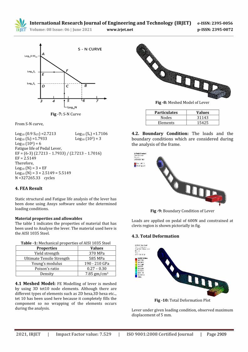
4.1 Meshed Model: FE Modelling of lever is meshed by using 3D tet10 node elements. Although there are different types of elements such as 2D hexa,3D hexa etc.., tet 10 has been used here because it completely fills the component so no wrapping of the elements occurs during the analysis.
Fig -8: Meshed Model of Lever
Particulates Values
Nodes 31143 Elements 15425
4.2. Boundary Condition: The loads and the boundary conditions which are considered during the analysis of the frame.
Fig -9: Boundary Condition of Lever
Loads are applied on pedal of 600N and constrained at clevis region is shown pictorially in fig.
4.3. Total Deformation
Fig -10: Total Deformation Plot
Lever under given loading condition, observed maximum displacement of 5 mm.

International Research Journal of Engineering and Technology (IRJET) e-ISSN: 2395-0056
Volume: 08 Issue: 06 | June 2021 www.irjet.net p-ISSN: 2395-0072
2021, IRJET | Impact Factor value: 7.529 | ISO 9001:2008 Certified Journal | Page 2910
4.4. Equivalent Von-Mises Stress
Fig -11: Equivalent Von-Mises Stress Plot
From the above plot it is observed that the Maximum Von-Mises stress of 170.7MPa, of which is much lesser than yield stress of the material 250 MPa. So designed lever meets the Design requirement.
4.5. Fatigue Life
Fig -12: Fatigue Life Plot
Fatigue Life analysis of Ansys result is computed within all finite elements. Ansys result under given loading condition gives maximum fatigue life of 1*106 cycles, calculated value does not exceed the Finite Element Analysis result hence the entry was qualified.
5. CONCLUSIONS
The FE model of Lever Pedal is successfully analyzed using Ansys software and Analysis result contour plots are validated with the following conclusions have been made before the close of the contest.
The fatigue life of the component can also be found out using the results obtained by these software’s by which company can decide how much the warranty can be given for its manufactured components upon testing.
The analysis of the components using these software’s involves understanding of basic engineering concepts and physics behind it how
the forces act and stress developed in the components.
Human can ride the bicycle with less effort. There's less stress to the knees, ankles and hips and it's easy to store safely. This project work is more accomplished and these concepts works on all bikes: Rickshaw, kid’s bikes, Mountain bikes and Beach Cruisers.
6. REFERENCES
[1] H. E. Ang, C. L. Tan, “Stress Concentrations at Holes in Thin Rotating Discs”, Nanyang Technological Institute, Singapore. Mimeche, Carleton University, Ottawa, Canada, Journal of Strain Analysis, Vol 23 No 4, 1988.
[2] H. Fessler, T. E. Thorpe “Optimization Of Stress Concentrations At Holes In Rotating Discs”, University Of Nottingham, University Park, Nottingham, Journal Of Strain Analysis, Vol 2 No 2,1967
[3] Vairakanna, M.Chandran, “Design And Material Study Of Race Bike Crank” Dr. Mgr University, Chennai, India, 2017
[4] Mohammed Asif Kattimani, Pandit.K, “Finite Element Analysis of Bicycle Crank” Lords Institute of Engineering and Technology, Hyderabad, IJSTE/ Volume 3 / Issue 10 / 045, April 2017
[5] Miss. S. Chandana, Mr. R.Shiva Kumar, Mr. S. Suhas Mr. N.Sai Charan, Mr. Alapati Bhargav, “Design And Analysis Of Shaft Driven Bicycle”, IJRI-International Journal Of Resarch And Innovation, 2017.
[6] K. Rajasuthan, G. Balaji, M. Palpandi, “Design of An Efficient Gear Driven Bicycle”, International Journal of Engineering Sciences & Research Technology, December 2016.
[7] Khan Hassan Zakariya, Kolkar Abhimanyu Dashrath, Quazi Azhar Husain Farrukhzama, Assistant Prof. Shivraj Kavhale, “Design and Fabrication of Chainless Bicycle” International Research Journal of Engineering and Technology (IRJET) Volume 5, Issue,2018.
[8] Mayur Linagariya, Dignesh Savsani, “Dynamic Chainless Bicycle”, IJAREST-International Journal of Advance Research in Engineering, Science & Technology, Vol.2, Issue 5,2015.

International Research Journal of Engineering and Technology (IRJET) e-ISSN: 2395-0056
Volume: 08 Issue: 06 | June 2021 www.irjet.net p-ISSN: 2395-0072
2021, IRJET | Impact Factor value: 7.529 | ISO 9001:2008 Certified Journal | Page 2911
7. BIOGRAPHIES
Shivakumar R V working as Assistant Professor in Department of Mechanical Engineering, JSS Academy of Technical Education, Noida. Research areas Includes Strength of Materials, Machine Design, FEM & FEA. Mohammad Zaki is Student in Department of Mechanical Engineering, JSS Academy of Technical Education, Noida. Ritic Jain is Student in Department of Mechanical Engineering, JSS Academy of Technical Education, Noida. Devendra Kumar is Student in Department of Mechanical Engineering, JSS Academy of Technical Education, Noida. Ranjit Singh is Student in Department of Mechanical Engineering, JSS Academy of Technical Education, Noida.