design and fabrication two degree of freedom free
TRANSCRIPT

DESIGN AND FABRICATION TWO DEGREE OF FREEDOM FREE VIBRATION
TRANSLATION MOTION TEST RIG
MUHAMMAD MAGHRIBI BIN SELAMAT
Report submitted in partial fulfillment of the requirements
For the award of Diploma in Mechanical Engineering
Faculty of Mechanical Engineering
UNIVERSITI MALAYSIA PAHANG
JUNE 2013

v
ABSTRACT
This project is about the designing and fabrication the two degree of freedom free
vibration translation motion test rig. The objective of this project is to design and
fabricate the two degree of freedom free vibration translation motion test rig. The
study on the free vibration system of two degree of freedom is very important. This
theory need to be carried out by doing experimental study. This test rig will be
developed based on the vibration fundamental knowledge. The fabrication process
starts with understanding the fundamental of mechanical vibration. Sketching and
design process will be developed in multiple choices in order to select the best design
concept of the test rig. Material selection and the factor of the selection also have
been listed based on the appropriate criteria predetermined. The selection material
will undergo several fabrication process based on the chose design. Finally the test rig
will be tested in the vibration laboratory.

vi
ABSTRAK
Projek ini adalah mengenai mereka bentuk dan penghasilan alat uji kaji getaran bebas
dua darjah dalam pergerakan yang sehala. Objektif projek ini adalah untuk mereka
bentuk dan menghasilkan alat uji kaji getaran bebas dua darjah dalam pergerakan
yang sehala. Kajian ke atas getaran bebas dua darjah adalah sangat penting. Teori ini
hendaklah dilaksanakan dengan menjalankan kajian uji kaji. Alat uji kaji ini akan
dihasilkan dengan berlandaskanckepada pengetahuan asas getaran. Proses
penghasilan bermula dengan pemahaman kepada pengetahuan asas getaran
mekanikal. Beberapa lakaran dan rekaan bentuk akan dihasilkan supaya satu rekaan
bentuk yang terbaik dapat dipilih daripada rekaan bentuk yang lain. Pemilihan bahan
dan faktor pemilihan itu juga telah disenaraikan berdasarkan kriteria yang sesuai yang
telah ditetapkan. Bahan yang telah dipilih akan menjalani beberapa proses
penghasilan berdasarkan kepada rekaan bentuk yang telah dipilih. Akhirnya, alat uji
kaji ini akan diuji di dalam makmal getaran.

vii
TABLE OF CONTENTS
Page
SUPERVISOR’S DECLARATION
STUDENT’S DECLARATION
ACKNOWLEDGEMENTS
ABSTRACT
ABSTRAK
TABLE OF CONTENTS
LIST OF TABLES
LIST OF FIGURES
LIST OF SYMBOLS
LIST OF ABBREVIATIONS
ii
iii
iv
v
vi
vii
x
xi
xiii
xiv
CHAPTER 1 INTRODUCTION
1.1 General Introduction 1
1.2 Problem Statement 2
1.3 Project Objective 2
1.4 Project Scope 2
CHAPTER 2 LITERATURE REVIEW
2.1 Introduction 3
2.2 Vibration 3
2.2.1 Undamped Free Vibration
2.2.2 Damped Free Vibration
4
5
2.3 Degree of Freedom 6
2.3.1 One Degree of Freedom Vibration System
2.3.2 Two Degree of Freedom Vibration System
7
7
2.4 Material and Apparatus 8
2.4.1 Aluminium Profile
2.4.2 Spring
2.4.3 Mass
8
9
9

viii
2.5 Sensor 10
2.5.1 Accelerometer Sensor
2.5.2 LVDT Sensor
2.5.3 Tachometer Sensor
10
11
13
CHAPTER 3 METHODOLOGY
3.1 Introduction 15
3.2 Methodology Process Flow Chart 16
3.3 Design Concept 17
3.3.1 First Design
3.3.2 Second Design
3.3.3 Third Design
3.3.4 Fourth Design
18
19
20
21
3.4 Design Selection 22
3.5 Final Design 23
3.6 Material Selection 23
3.6.1 Frame
3.6.2 Rod
3.6.3 Disc
3.6.4 Bolt and Nut
24
25
25
25
3.7 Fabrication Method 26
3.7.1 Measuring
3.7.2 Cutting
3.7.3 Drilling
3.7.4 Milling
3.7.5 Threading
3.7.6 Finishing
26
28
29
30
31
33
CHAPTER 4 RESULT AND DISCUSSION
4.1 Introduction 34
4.2 Test Rig 34
4.3 Part of The Test Rig 37
4.3.1 Test Rig Frame
4.3.2 Steel Rod
4.3.3 Steel Plate
4.3.4 Aluminium Disc
4.3.5 Screw Nut
37
38
38
39
39

ix
4.4 Discussion 40
4.4.1 Comparison with The Existing Test Rig 40
4.4.2 Problem Description 41
CHAPTER 5 CONCLUSION AND RECOMMENDATIONS
5.1 Conclusion 42
5.2 Recommendations 43
REFERENCES 43
APPENDICES
A1 Test rig frame drawing with dimension 46
A2 Aluminium disc drawing with dimension 47
A3 First rod drawing with dimension 48
A4 Second rod drawing with dimension 49
A5 Screw nut drawing with dimension 50
A6 First steel plate drawing with dimension 51
A7 Second steel plate drawing with dimension 52
B1 Gantt chart 53

x
LIST OF TABLES
Table No. Title Page
3.1 Concept selection 22
4.1 The comparison between existing test rig and the new
test rig
39
xi
LIST OF FIGURES
Figure No. Title Page
2.1 The graph of undamped free vibration 5
2.2 The graph of damped free vibration 5
2.3 Six degrees of freedom of helicopter model 6
2.4 One degree of freedom system models 7
2.5 Two degree of freedom system models 8
2.6 Spring 9
2.7 Masses 9
2.8 Accelerometer sensor 10
2.9 LVDT sensor, cross sectional view and parts 12
2.10 Tachometer sensor 14
3.1 Flow Chart 16
3.2 First design front and isometric view 18
3.3 Second design front and isometric view 19
3.4 Third design front and isometric view 20
3.5 Fourth design front and isometric view 21
3.6 Final desgn 23
3.7 Aluminium profile 24
3.8 Aluminium L-bar 24
3.9 Aluminium sheet metal 25
3.10 Bolt and nuts 26
3.11 Measuring process and measuring instruments 27
3.12 Hand hacksaw and correct way to use hand hacksaw 28
3.13 Drilling process 29
3.14 Milling process 30
3.15 Taps and threading process by using tap wrench 31
3.16 Die and threading process by using die holder 32
3.17 Spray paint 33
4.1 Test rig front and isometric view 35
4.2 Experiment process on the test rig by using load of 60N 36

xii
LIST OF FIGURES
Figure No. Title Page
4.3 Test rig frame front and isometric view 37
4.4 Steel rods 38
4.5 Steel plates 38
4.6 Aluminium discs 39
4.7 Screw nuts 39

xiii
LIST OF SYMBOLS
x Displacement of the mass
x1 Displacement of first mass
x2 Displacement of second mass
θ1 First angular displacement
θ2 Second angular displacement
m mass
m1 First mass
m2 Second mass
k Spring stiffness
k1 First spring stiffness
k2 Second spring stiffness

xiv
LIST OF ABBREVATIONS
LVDT Linear Variable Differential Transformer
RVDT Rotary Differential Transformer
DOF Degree of freedom
RPM Revolution per minute
3D 3-Dimentional

CHAPTER 1
INTRODUCTION
1.1 GENERAL INTRODUCTION
Vibration study is very important and useful in our life. Vibration is not only
applied in the mechanical structural system, but it is also exhibited in our respiratory
system that generates our heart beat. Moreover, the sound produced in this world is
actually created by the vibration. The sound wave that moves in air is invisible, only
the effect and energy of the sound wave can be identified by human being. The
modern physics also say that even the atoms which consist of the entire universe
vibrate incessantly. Thus vibration and its effects are very common in our daily life.
However, most vibrations are undesirable in machines and structures because the
vibration can cause energy loss, machine damage or break down, induce fatigue and
many more. Therefore, the study of mechanical vibration filed is very important to
overcome these problems.
This project is about to design and fabricate the two degree of freedom free
vibration test rig. Vibration can be identified as a response of a system to an internal
or external stimulus that caused it to oscillate and vibrate. In this project, the vibrating
systems were fabricated. The test was conducted upon this test rig in order to study
the two degree of freedom free vibration. Hence, through this project the further
understanding about the vibration will be enhanced.

2
1.2 PROBLEM STATEMENT
In the UMP vibration laboratory there are only have one degree of freedom
vibration test rig, either free or forced vibration. With the significant of vibration
knowledge and had been decided to extend the knowledge to the two degree of
freedom vibration test rig. This test rig organized free vibration on the translation
motion.
1.3 PROJECT OBJECTIVE
The objective of this project is to design and fabricate two degree of freedom
free vibration translation motion test rig.
1.4 PROJECT SCOPE
This project focuses on the following matter:
1. Carry out the literature review from previous fellow research and other
sources such as journal and text book.
2. Sketch and design the concept of the test rig.
3. Select the material for the chose design.
4. Fabricate the chose design with the fundamental of vibration knowledge.
5. Evaluate and test the test rig.

CHAPTER 2
LITERATURE REVIEW
2.1 INTRODUCTION
This chapter will be more focused on the two degree of freedom free
vibration translation motion. The vibration fundamental study will be briefly
explained. In addition, several types of sensor that have been used in the vibration
laboratory such as accelerometer, LVDT and tachometer will be briefly explained in
term of its function and the way how to use it.
2.2 VIBRATION
Any repeated motion of an object after in a time interval is to be said as a
vibration or oscillation. The continuous alternating of energy from potential energy
into kinetic energy and from kinetic energy to potential energy is occurred upon an
object during the vibration and oscillation process. Basically there are two types of
vibrations, which are forced vibration and free vibration. The damped vibration
occurred when the vibrating system undergoes damping process. The damped
vibration can be categorized into two types which are damped force vibration and
damped free vibration. On the other hand, when the damping process is neglected
upon the vibrating system, this vibration is called as undamped vibration. The
undamped vibration also divided into two categories which are undamped free
vibration and undamped force. (Bhave Srikant, 2004)

4
Vibration is a result of the combination of inertia and elastic forces effects.
Inertia of a moving object can be expressed in terms of the mass, moment of inertia
and the displacement of the object. And the elastic force can be expressed in terms of
the displacement or stiffness of the elastic member like spring. (A.A. Shabana, 1996)
2.2.1 UNDAMPED FREE VIBRATION
A free vibration is a vibration that occurred naturally with no energy or force
being added to the vibrating system. An object will undergo free vibration process
when it oscillated or vibrated only with an initial disturbance and with no external
forces acting on that object after the initial disturbance. In this case, when an object is
moved away from it rest position, there is a natural force that will return that object to
its rest position. The damped vibration will be occurred when the object energy is
dissipated during the motion. While if there is no dissipation of the energy of an
object during its motion, so it is called as undamped free vibration. (J.S. Rao and K.
Gupta, 1998).
An Undamped free vibration of a system is vibration that occurs in absence
of any damping. The total mechanical energy due to initial conditions is conserved
and the system can vibrate forever because of the continuous exchange between the
kinetic and potential energies. (Rao V. Dukkipati and J. Srinivas, 2004) In many
cases, the damping will still occurred during the oscillation, but in this case the
amount of the damping is too small so that it can be disregarded for most engineering
purpose. (J.S. Rao and K. Gupta, 1998) The figure below shows the amplitude of the
undamped free vibration remains constant since there is no dissipation of the energy.

5
Figure 2.1: The graph of undamped free vibration.
Source: Jay Newman, 2008
2.2.2 DAMPED FREE VIBRATION
Basically the damping will occur in most situations. This is because the
resistance and obstruction will happen due to the surrounding factor like friction.
Therefore the amplitude of the damped free vibration is gradually becomes smaller
and smaller until the oscillation stop as shown in the figure below. (J.S. Rao and K.
Gupta, 1998)
Figure 2.2: The graph of damped free vibration.
Source: Jay Newman, 2008

6
2.3 DEGREE OF FREEDOM
The position of a system of an object is called its configuration. The
configuration is defined as the geometric location of all the masses of a system. The
independent coordinates is required to specify the configuration of a dynamic system
is called generalized coordinates. The number of generalized coordinates is known as
the number of degree of freedom (DOF) of a dynamic system. There are six number
degrees of freedom. Three coordinates are to define the translation motions which are
moving up and down (heaving), moving left and right (swaying) and moving forward
and backward (surging). While others three coordinates to define the rotation motions
which are tilts forward and backward (pitching), swivels left and right (yawing),
pivots side to side (rolling). (Rao V. Dukkipati and J. Srinivas, 2004)
Figure 2.3: Six degrees of freedom of helicopter model.
Source: Edward Ashford Lee and Sanjit Arunkumar Seshia, 2011

7
2.3.1 ONE DEGREE OF FREEDOM VIBRATION SYSTEM
A vibration system is said to be have one degree of freedom if it geometrical
position moves in one direction only. One degree of freedom system is the simplest
vibration system system. It moves by translation along one direction or rotate about
one axis. The motion of one degree freedom system is a sinusoid which having only a
single frequency. This one degree of freedom system has been applied in the
mechanical structural system. (J.P. Den Hartog, 1985)
Figure 2.4: One degree of freedom system models (a) Vertically manner, (b)
Horizontally manner. x
Source: Rao V. Dukkipati and J. Srinivas, 2004
2.3.2 TWO DEGREE OF FREEDOM VIBRATION SYSTEM
Even though single of freedom models can approximate many mechanical or
structural systems, most of the system have several restrains and therefore required to
be represented by several degrees of freedom. The number of degrees of freedom that
a system processes is equal to the number of independent coordinates necessary to
describe the motion of the system. A system that moves in two directions is called
two degree of freedom vibration systems. (S. Graham Kelly, 2011)
(a)
(b)
8
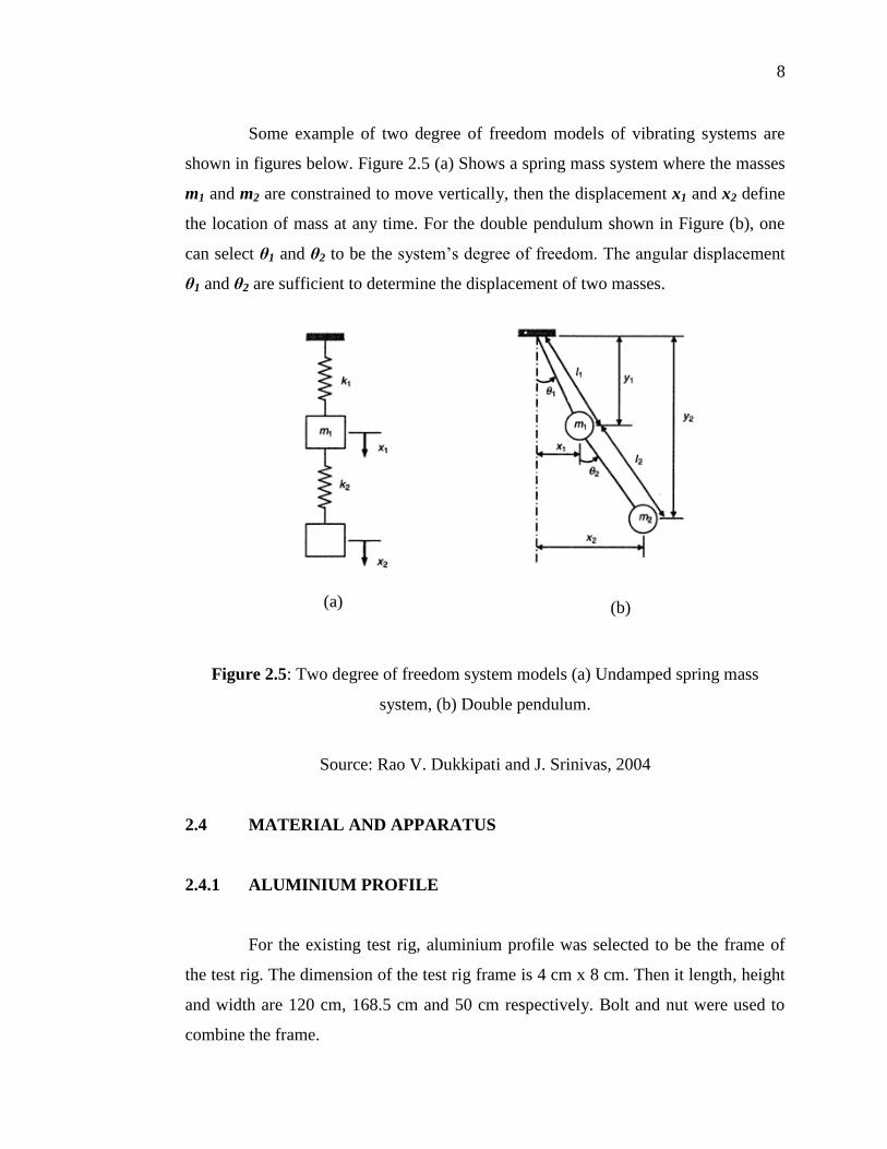
Some example of two degree of freedom models of vibrating systems are
shown in figures below. Figure 2.5 (a) Shows a spring mass system where the masses
m1 and m2 are constrained to move vertically, then the displacement x1 and x2 define
the location of mass at any time. For the double pendulum shown in Figure (b), one
can select θ1 and θ2 to be the system’s degree of freedom. The angular displacement
θ1 and θ2 are sufficient to determine the displacement of two masses.
Figure 2.5: Two degree of freedom system models (a) Undamped spring mass
system, (b) Double pendulum.
Source: Rao V. Dukkipati and J. Srinivas, 2004
2.4 MATERIAL AND APPARATUS
2.4.1 ALUMINIUM PROFILE
For the existing test rig, aluminium profile was selected to be the frame of
the test rig. The dimension of the test rig frame is 4 cm x 8 cm. Then it length, height
and width are 120 cm, 168.5 cm and 50 cm respectively. Bolt and nut were used to
combine the frame.
(a)
(b)

9
2.4.2 SPRING
Basically only one spring was used for the existing test rig. This is because
the single degree of freedom free vibration system was applied by the existing test
rig.
Figure 2.6: Spring
2.4.3 MASS
The mass was used to be the weight for vibration test rig. The different
weight of the mass will be used in every vibration test rig experiment in order to get
the different output results.
Figure 2.7: Masses

10
2.5 SENSOR
Recently there are various types of the sensors used to measure the vibration
shock. In the UMP vibration laboratory, the common three types of sensors were used
such as accelerometer sensor, Linear Variable Differential Transformer (LVDT)
sensor and tachometer sensor.
2.5.1 ACCELEROMETER SENSOR
Accelerometer is a device that measures proper acceleration, the acceleration
experience relative to free fall. Single and multi-models are available to detect
magnitude and direction of the acceleration as a vector quantity and can be used to
measure acceleration, vibration shock and falling. Accelerometer is quantified in the
SI unit meters (m/s2). (Anthony Lawrence, 2001) Accelerometer sensors measure the
difference between any linear acceleration in the acceleration’s reference frame and
the earth’s gravitational field vector. In absence of linear acceleration, the
acceleration output is a measurement of the rotated gravitational filed vector and can
be used to determine the accelerometer angular orientation. (J. Valldorft and W.
Gessner, 2004)
Figure 2.8: Accelerometer sensor

11
2.5.2 LVDT SENSOR
The Linear Variable Differential Transformer (LVDT) is type of electrical
transformer used for measuring linear displacement. A counterpart of this device is
used to measure rotary displacement is called Rotary Differential Transformer
(RVDT). The linear variable differential transformer has three solenoid coils placed
end to end around a tube. The center coil is the primary and two outer coils are the
secondary. (U.A. Bakshi and A.V. Bakshi, 2008)
A cylindrical ferromagnetic core, slides along the axis of the tube. An
alternating current is driven through the primary causing a voltage to be induced in
each secondary proportional to its mutual inductance with the primary. The frequency
is usually in the range 1 to 10 kHz. As the core moves, these mutual inductance
changes causing the voltages induced in the secondary to change. The coils are
connected in reverse series so that the output voltage is the difference between the
two secondary voltages. When the core in these two coils so the output voltage is
theoretically zero. In practice minor variations in the way in which the primary is
coupled to each secondary means that a small voltages is output when the core is
central. When the core is displaced in one direction, the voltage in a coil increased as
the other decreased causing the output voltage to increase from zero to a maximum.
This voltage is in phase with the primary voltage. When the core moves in the other
direction the output voltage also increase from zero to a maximum but its phase is
opposite to that of the primary. The magnitude of the output voltage is proportional to
the distance moved by the core which is why the device is described as having a
linear response to displacement. The phase of the voltage indicates the direction of
the displacement. (David S. Nyce, 2003)

12
Figure 2.9: (a) LVDT sensor, (b) Cross-sectional view, (c) Part of LVDT sensor
Source: David S. Nyce, 2003
(a)
(b)
(c)

13
2.5.3 TACHOMETER SENSOR
The tachometer also called revolution counter which is an instrument used to
measure the rotation or speed of a shaft and disc. Generally these measurements are
rated in round per minute (R.P.M). The traditional tachometer is actually exposed to
the high dangerous level and less safety. Recently digital tachometers giving a direct
numeric value output that commonly used nowadays. In its many cases, a tachometer
is used to measure the speed at which a mechanical device is rotating. Basically the
traditional tachometer is required the physical contact between the instrument and the
device that need to be measured. Therefore the traditional tachometer is more
dangerous compared to the recently tachometer which can take the measurement in a
distance and contactless to the device that need to be measured. (M. Jouneh, 2002 and
Alan S. Morris and Reza Langari, 2012)
2.5.3.1 VOLTAGE BASED TACHOMETER
Voltage based tachometer is required a source of voltage to determine the
speed and perform various other tasks. An example of voltage based tachometer is the
DC generator tachometer. It has a very simple way of it operation. The amount of
voltage which is being produced will be directly proportional to the speed of the
tachometer.
2.5.3.1 FREQUENCY TYPE TACHOMETER
Another type of tachometer is frequency type tachometer. This type of
tachometer is calculated the amount of pulse produced due to a rotating filed
tachometer. It is required a higher of precision and digital circuitry as opposed to the
voltage based tachometer which is barely simple to use.