design and fabrication of vartm fabricated skin panels ... · such as fibersim and simdesigner...
TRANSCRIPT
Design and Fabrication of VARTM Fabricated Skin Panels with Integrated Hollow Hat Stiffeners
Dirk Heider1,2,*, Pit Schulze1, Hope Deffor1, John Tierney1, and J.W. Gillespie, Jr.1,3,4 1*Center for Composite Materials
2Department of Electrical Engineering, 3Department of Materials Science and Engineering
4Department of Civil and Environmental Engineering University of Delaware
Newark, DE 19716 Abstract
Research that supports the application of Vacuum-Assisted Resin Transfer Molding (VARTM) for aerospace applications is being performed at the University of Delaware Center for Composite Materials (UD-CCM). The long-term objective of the research is to improve VARTM repeatability equivalent to autoclave processing with specific properties (property/weight) that are close to autoclave-processed part levels at a lower cost.
Potential applications of this process include skin panels with integrated stiffeners used in aerospace applications. This paper is evaluating the replacement of an aluminum trailing edge with a graphite epoxy construction. A washable mandrel material was used to fabricate washable hat stiffeners. The process has been developed to repeatable infuse a toughened epoxy resin and hollowed stiffened components have been fabricated. Computational simulation was used to design and optimize the hat stiffened composite part to match the response of an existing all metal component. A baseline aluminum analysis provided target in-plane and bending stiffness response requirements for the composite design under equivalent loading. Simulation were also used to evaluate manufacturing producibility such a draping of the fabric and resin infusion in the final component.
Introduction Stiffened aluminum shell structures are used extensively in aircraft structures due to
their outstanding strength, stiffness and lightweight properties. Nevertheless, the maintenance burden due to corrosion in particular for thin gauged components is high. Composites is good replacement material candidates due to its improved durability and corrosion resistance [1]. In this work, design and optimization of a composite stiffened panel (see Figure 1) for an aging aircraft is conducted with the goal of matching the stiffness response of the existing aluminum panel. This requires a new design involving materials selection, engineering design and analysis and process development using low cost molding technology. Ultimately, the goal is to develop the design and fabrication methodology to provide the framework for a cost-effective body parts replacement program for aging aircraft fabricated with aluminum panels.

Figure 1: A typical hat stiffened panel
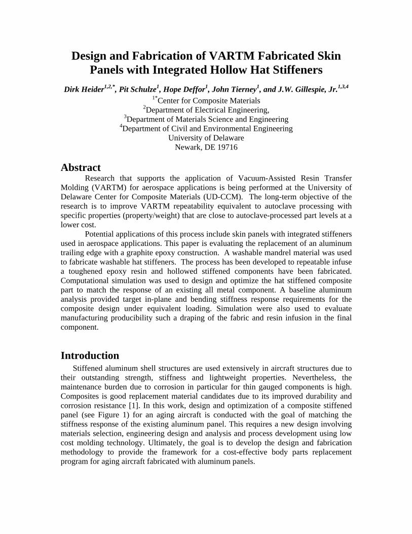
The overall design strategy for this effort, shown in Figure 2, involves a preliminary study of the baseline aluminum part followed by design and optimization of the composite structure based on results from the all metal design. Initially, all functional requirements including geometric envelope, loads, stiffness specification, environment, manufacturing, materials selection and maintenance considerations are defined. The ‘baseline’ aluminum analysis provides target in-plane and bending stiffness response requirements for the composite design under equivalent loading. CATIAv5r17 is used as the CAD environment due to the convenient workbench interfaces available for defining and designing composites with additional producibility and structural analysis programs such as FiberSIM and SimDesigner (Patran/Nastran functionality). Having all these ‘workbenches’ within the one environment greatly enhances design productivity and optimization for composite structures. Having the ability to define composite laminates, conduct drapability and FEA studies while maintaining mesh-to-geometric associatively results in a very efficient method for manufacturing and structural optimization.
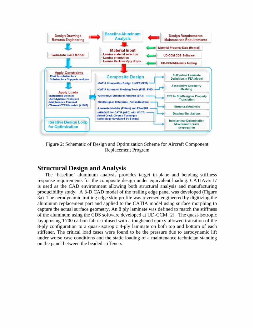
Figure 2: Schematic of Design and Optimization Scheme for Aircraft Component
Replacement Program
Structural Design and Analysis
The ‘baseline’ aluminum analysis provides target in-plane and bending stiffness response requirements for the composite design under equivalent loading. CATIAv5r17 is used as the CAD environment allowing both structural analysis and manufacturing producibility study. A 3-D CAD model of the trailing edge panel was developed (Figure 3a). The aerodynamic trailing edge skin profile was reversed engineered by digitizing the aluminum replacement part and applied to the CATIA model using surface morphing to capture the actual surface geometry. An 8 ply laminate was defined to match the stiffness of the aluminum using the CDS software developed at UD-CCM [2]. The quasi-isotropic layup using T700 carbon fabric infused with a toughened epoxy allowed transition of the 8-ply configuration to a quasi-isotropic 4-ply laminate on both top and bottom of each stiffener. The critical load cases were found to be the pressure due to aerodynamic lift under worse case conditions and the static loading of a maintenance technician standing on the panel between the beaded stiffeners.
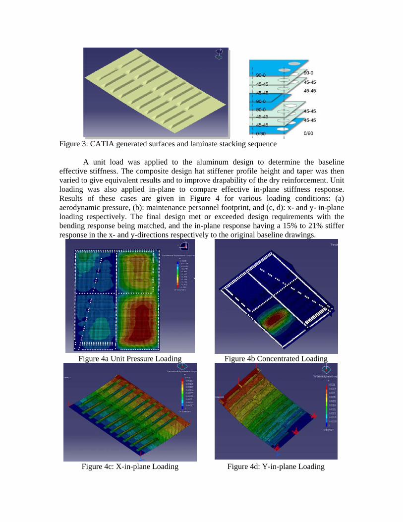
Figure 3: CATIA generated surfaces and laminate stacking sequence
A unit load was applied to the aluminum design to determine the baseline
effective stiffness. The composite design hat stiffener profile height and taper was then varied to give equivalent results and to improve drapability of the dry reinforcement. Unit loading was also applied in-plane to compare effective in-plane stiffness response. Results of these cases are given in Figure 4 for various loading conditions: (a) aerodynamic pressure, (b): maintenance personnel footprint, and (c, d): x- and y- in-plane loading respectively. The final design met or exceeded design requirements with the bending response being matched, and the in-plane response having a 15% to 21% stiffer response in the x- and y-directions respectively to the original baseline drawings.
Figure 4a Unit Pressure Loading Figure 4b Concentrated Loading
Figure 4c: X-in-plane Loading Figure 4d: Y-in-plane Loading

One of the challenges of the composite replacement part design is the use of hollow
stiffeners to match the aluminum design. Conventional core materials were not considered due to their weight and water absorption potential. Thus, a new processing approach had to be developed. Hollow Stiffener Processing Approach
The aerospace industry is starting to take advantage of a variety of vacuum infusion processes due to its potential of fabricating high-quality components at low cost. These Vacuum Assisted Resin Transfer Molding (VARTM) -based manufacturing techniques are also capable of producing complex shaped 3D structures by incorporating permanent or removable cores. While there is a wide range of permanent core materials available, removable mandrels have not been explored widely. A lightweight soluble tooling material for the VARTM process has been investigated and will increase the number of potential applications significantly.
The water-soluble core material “Aquacore™” supplied by Advanced Ceramics Research, Inc., Tucson, AZ is used to mold the stiffener mandrel. The sand-like compound consists of a temperature resistant polymer filled with ceramic particles and it can be manually processed into complex shapes and temporarily protected against resin penetration. Recent studies of the castable core material by Li et al. [3] provided helpful guidance, investigating various mechanical tests and processing issues. Manufacturer information provided details about differences in compression strength and density as well [4]. Both references state compression properties that far exceed the requirements for the typical VARTM process. One issue with the VARTM fabrication is that the tooling material needs to be sealed so that there is no resin uptake during infusion. For many aerospace applications high-temperature toughened epoxy resins such as Cytec Cycom 977-20 have to be used and these resin systems require infusion temperatures around 167F (see Figure 5). These temperatures require a new sealing strategy to ensure that the seal survive the infusion temperatures and that ultimately the mandrel material can be completely dissolved after panel fabrication.
Figure 5: Processing cycle of Cycom 977-20 An epoxy resin formulated for high temperature tooling applications (Freeman “945”
Hi-Temp surface coat) was down-selected as it allows both brush and spray application and meets the temperature requirement. The thixotropic, aluminum-filled material features temperature resistance up to 300°F continuously. The material can be applied in a thin non-porous film (~0.02 in), requiring no more than 2 brushed coatings. Penetration into the soluble material is very small due to relatively high viscosity and particle content of the epoxy surface coat (Figure 6). The epoxy coating provided very good protection of

the soluble material and enabled the verification of complete sealing before infusion. Due to its non-soluble nature, the treated mandrel could be submerged in a water container and placed in a degassing chamber. Air was evacuated from the chamber, in case of present imperfections in the sealing coat, escaping air bubbles could be observed and the defect localized. The main disadvantage of a non-soluble sealing film is that it cannot be removed from the final part, leading to a slight increase in final weight compared to a fully flushed design.
Figure 6: Top- and bottom surfaces of mandrel, machined after first epoxy surface coat
A single stiffener carbon fiber/epoxy part was produced using a variation of the
SCRIMP process. The “Vacuum Assisted Process” (VAP) incorporates a membrane layer, which creates an impermeable barrier for the infused resin, thus allowing better venting and pressure distribution over the perform. Since the membrane prevents bleeding of resin out of the infused perform it generally significantly improves resin saturation and fill time, although fiber volume fractions will be typically lower than similar SCRIMP infused parts [5]. The manufactured part was visually inspected before machining small openings in form of two 0.25 in drilled holes placed in both end zones of the insert. The soluble material exhibited remarkable ease of dissolving and flushing with tap water. The soluble component of the insert could be removed to ~90% by weight within about 15 min. The remaining non-removable material mainly consists of epoxy sealing coat with a thin layer of ceramic material bonded to it, leading to a weight increase of less than 8% compared to the bare hollow carbon fiber/epoxy structure. No penetration of infusion resin into the soluble core material was observed. Figure 7 illustrates the laminate components in a sectioned view of the hollow prototype.
Carbon fiber top skin
Carbon fiber bottom skin
Hollow volume after core removal
Non-removable epoxy sealing coat
Figure 7: Detail of prototype cut along the length of the hollow stiffener Virtual Manufacturing Scale-Up
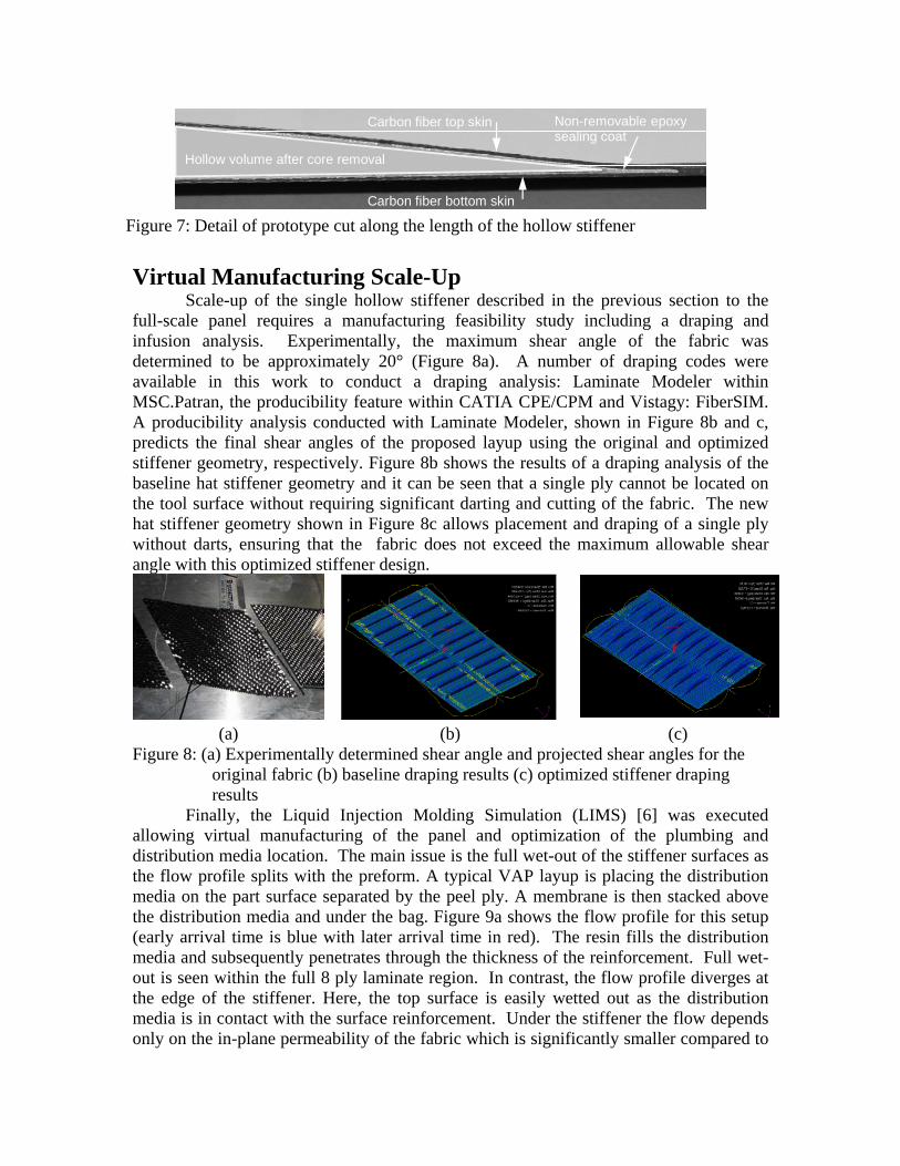
Scale-up of the single hollow stiffener described in the previous section to the full-scale panel requires a manufacturing feasibility study including a draping and infusion analysis. Experimentally, the maximum shear angle of the fabric was determined to be approximately 20° (Figure 8a). A number of draping codes were available in this work to conduct a draping analysis: Laminate Modeler within MSC.Patran, the producibility feature within CATIA CPE/CPM and Vistagy: FiberSIM. A producibility analysis conducted with Laminate Modeler, shown in Figure 8b and c, predicts the final shear angles of the proposed layup using the original and optimized stiffener geometry, respectively. Figure 8b shows the results of a draping analysis of the baseline hat stiffener geometry and it can be seen that a single ply cannot be located on the tool surface without requiring significant darting and cutting of the fabric. The new hat stiffener geometry shown in Figure 8c allows placement and draping of a single ply without darts, ensuring that the fabric does not exceed the maximum allowable shear angle with this optimized stiffener design.
(a) (b) (c)
Figure 8: (a) Experimentally determined shear angle and projected shear angles for the original fabric (b) baseline draping results (c) optimized stiffener draping results
Finally, the Liquid Injection Molding Simulation (LIMS) [6] was executed allowing virtual manufacturing of the panel and optimization of the plumbing and distribution media location. The main issue is the full wet-out of the stiffener surfaces as the flow profile splits with the preform. A typical VAP layup is placing the distribution media on the part surface separated by the peel ply. A membrane is then stacked above the distribution media and under the bag. Figure 9a shows the flow profile for this setup (early arrival time is blue with later arrival time in red). The resin fills the distribution media and subsequently penetrates through the thickness of the reinforcement. Full wet-out is seen within the full 8 ply laminate region. In contrast, the flow profile diverges at the edge of the stiffener. Here, the top surface is easily wetted out as the distribution media is in contact with the surface reinforcement. Under the stiffener the flow depends only on the in-plane permeability of the fabric which is significantly smaller compared to
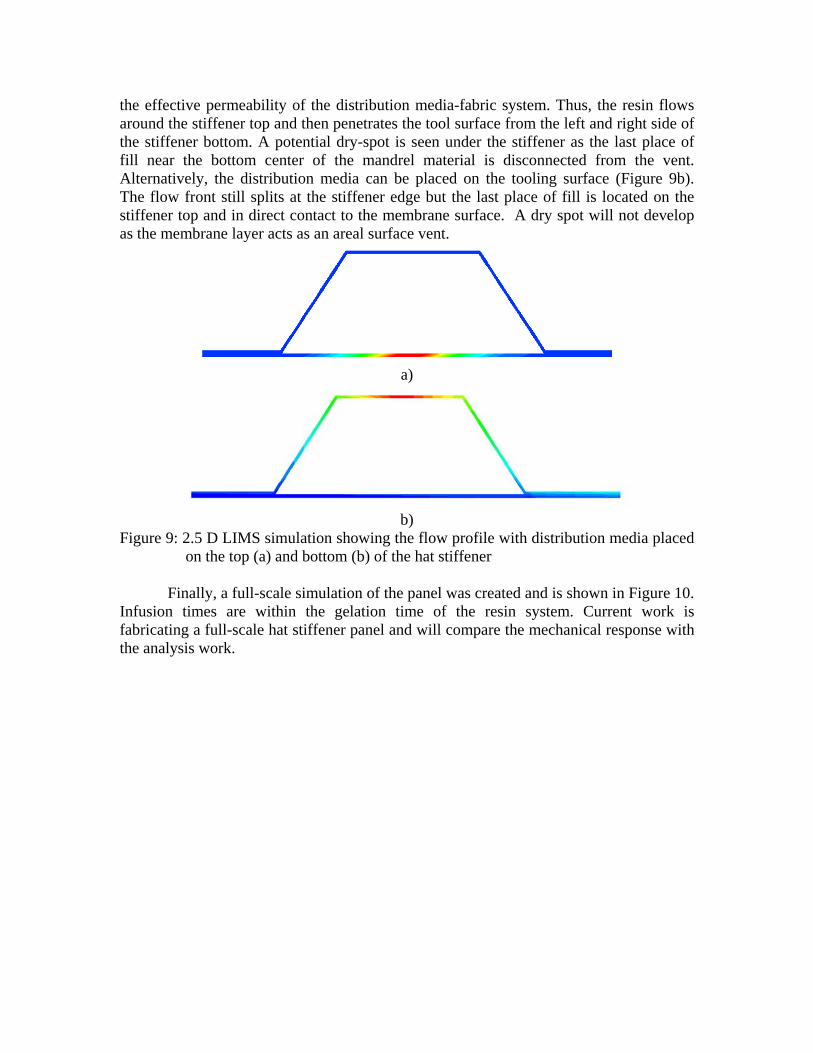
the effective permeability of the distribution media-fabric system. Thus, the resin flows around the stiffener top and then penetrates the tool surface from the left and right side of the stiffener bottom. A potential dry-spot is seen under the stiffener as the last place of fill near the bottom center of the mandrel material is disconnected from the vent. Alternatively, the distribution media can be placed on the tooling surface (Figure 9b). The flow front still splits at the stiffener edge but the last place of fill is located on the stiffener top and in direct contact to the membrane surface. A dry spot will not develop as the membrane layer acts as an areal surface vent.
a)
b)
Figure 9: 2.5 D LIMS simulation showing the flow profile with distribution media placed on the top (a) and bottom (b) of the hat stiffener
Finally, a full-scale simulation of the panel was created and is shown in Figure 10.
Infusion times are within the gelation time of the resin system. Current work is fabricating a full-scale hat stiffener panel and will compare the mechanical response with the analysis work.

Last PlaceOf fill
Bag Side Tool Side
Figure 10: LIMS simulation of the full-scale stiffened panel Conclusions
A standard design and analysis methodology within the CATIA environment has been developed that allows for CAD design of composites as well as structural optimization of the composite replacement part. The analysis and manufacturing producibility study shows the benefit of the virtual simulation approach. In addition, a new washable material and associate VARTM process has been investigated. Sub-scale elements have been fabricated and demonstrated the successful manufacturing approach. Together, the study lays the foundation for the rapid and low-cost replacement of aluminum based aerospace panels
Acknowledgement
The authors gratefully acknowledge the support of the Office of Naval Research through support of the National Testbed for Intelligent VARTM Processing of Polymer-Matrix Composites (N00014-99-1-0636) and Advanced Materials Intelligent Processing Center under grant number N00014-04-1-0891. The authors would also like to thank Dan Marlowe (Naval Air Systems Command Depot, Jacksonville, FL) and Jerry Rubinsky (NAVAIR, Patuxent River, MD) for their support in this project and Jeffrey Lawrence (UD-CCM) conducting the full-scale LIMS simulation.
References 1. "Boeing Opts for Composites for 7E7", Reinforced Plastics, v47, n 7, p10,
July/August, 2003 2. CDS Software Homepage: http://www.ccm.udel.edu/Tech/CDS/Intro.htm 3. Li Ma et al., SAMPE Journal, 43 (5), pp. 24-33 (2007)

4. Available at company website Advanced Ceramics Research, Inc.; http://www.acrtucson.com/
5. J. Krehl et al., Journal of Composite Materials, 38 (20), pp. 1803-1814 (2004) 6. Liquid Injection Molding Simulation (LIMS) A Comprehensive Tool to Design,
Optimize and Control the Filling Process in Liquid Composite Molding, Simacek, P., Advani, S.G. and Binetruy, C., JEC - Composites, n 8, April 2004, p 58-61