design and fabrication of rack and pinion
TRANSCRIPT

7/25/2019 Design and Fabrication of Rack and Pinion
http://slidepdf.com/reader/full/design-and-fabrication-of-rack-and-pinion 1/5
Middle-East Journal of Scientific Research 20 (6): 744-748, 2014
ISSN 1990-9233
© IDOSI Publications, 2014
DOI: 10.5829/idosi.mejsr.2014.20.06.11372
Corresponding Author: A. Thirugnanam, Department of Mechanical Engineering,
Bharath Institute of Science and Technology, P.O 600073, Chennai, India.
744
Design and Fabrication of Rack and Pinion Lift
A. Thirugnanam, Praphul das and Lenin Rakesh
Department of Mechanical Engineering,
Bharath Institute of Science and Technology, P.O 600073, Chennai, India
Abstract: A Rack and Pinion Lift is composed of two gears and a Rack and Pinion arrangement. The flat helical
gear is the rack and the round helical gear is the pinion. The rack has teeth cut into it and they mesh the teeth
of the pinion gear. Also a spur gear is connected to the shaft of the pinion. And this gear is connected to
another gear by using a chain drive. One of the spur gear is connected to the shaft of the torque and transfer
power by using a chair. The motor is running by use of 12 v battery. A rack and pinion is used to convert
between rotary and linear motion. This rack and pinion lift is commonly used in many industrial applications.
A rack and pinion lift consists of a rack and a pinion engaging also transfer motion to or from a special kind of
spur gear called a rack consisting of series of teeth in a straight line on a flat surface. The invention relates to
rack and pinion lifts, which include a lift car which is driven via toothed wheels by means of an electromotor
along a rack carried by a lift mast, said car containing a control and maneuver unit for the electric motor with
a control and maneuver button set including floor call buttons, landing based call button units being connected
to said control and maneuver unit via a ground level unit from which also a power cable leads to the lift car.
In association with the lift car a sensor device is arranged to indicate passage of teeth of the rack or the
toothed wheel and produce corresponding position impulses, which represent the position of the lift car.
A micro computer system is connected for receiving the position impulses and for collecting and storing call
impulses from the call units and destination impulses from the button set of the control and maneuver unit and
based upon the position of the lift car ordering travel direction, retardation and stop of the lift car. Said micro
computer system includes on the one hand a programmable micro computer unit in the lift car with a register
for position impulse numbers corresponding to the positionsof the landings, inputs for landings and outputsfor controlling operation of the electric motor, on the other hand a micro computer unit scanning the call button
units with respect to their state and associated with the ground level unit and communicating with the
programmable micro computer unit in the lift car.
Key words: Rack and Pinion arrangement Rack and pinion lift consists Which represent the position
INTRODUCTION determines the speed that the rack moves as the pinion
A Rack and pinion gear system is composed of two system of cars to convert the rotary motion to the steering
gears. The normal helical gear is the pinion gear and the wheel to the side to side motion in the wheel [2].
straight helical gear is the rack. The rack has teeth cut into A rack and pinion consists of a pinion engaging and
it and they mesh the teeth of the pinion gear. Rack and transferring motion to or from a special kind of spur gear, pinion gear provides a greater feedback and steering called a rack, consisting of a series of teeth in a straight
sensation [1]. A well designed mechanism such as the line on a flat surface. The rack and pinion changes linear
rack and pinion gear save effort and time. The rack and motion into rotary motion, or vice versa the rack and
pinion is used to convert between rotary and linear pinion is used to convert between rotary and linear
motion. Rack and pinion can convert from rotary to linear motion. Rack and pinion can convert from rotary to linear
or from linear to rotary. The diameter of the gear or from linear to rotary. The diameter of the gear
turns. Rack and pinion are commonly used in the steering

7/25/2019 Design and Fabrication of Rack and Pinion
http://slidepdf.com/reader/full/design-and-fabrication-of-rack-and-pinion 2/5
Middle-East J. Sci. Res., 20 (6): 744-748, 2014
745
determines the speed that the rack moves as the pinion Cutting
turns. Rack and pinion are commonly used in the steering Drilling
system of cars to convert the rotary motion of to the Welding
steering wheel to the side to side motion in the wheel. Grinding
A rack and pinion consists of a pinion engaging and
transferring motion to or from a special kind of spur gear, Cutting: Cutting operations are done so as to make the
called a rack, consisting of a series of teeth in a straight materials in proper dimensions. The cutting operations are
line on a flat surface [3]. The rack and pinion changes done by the various cutters available in the market just
linear motion into rotary motion, or vice versa. like dewalt, black deccor etc. hack saw are used for soft
In a rack and pinion lift system, comprising a lift car, iron parts such as stainless steels [5].
electro motor means for driving said car along a lift mast
via rack and pinion means, a control unit in said car with Drilling: Drilling is a cutting process that uses a drill bit
a control buttons set including floor call buttons, call to cut or enlarge a hole in solid materials. The drill bit is a
button units on landings along said mast, means multipoint, end cutting tool. It cuts by applying pressure
connecting said call button units to said control unit and rotation to the workpiece, which forms chips at the
via a ground level unit, the improvement comprising. cutting edge [6].
The present invention relates to a rack and pinion lift
system, comprising a lift car electro motor means for Welding: Welding is a process for joining different
driving said car along a lift mast via rack and pinion materials.welding joins different metals or alloys with the
means, a control unit in said car with a control button set help of a number of processes in which heat is supplied
including floor call buttons, call button units on landings either electrically or by means of a gas torch.Heat and
along said mast, means connecting said call button units pressure are the important requirement in welding.
to said control unit via a ground level unit.
Micro computer controlled floor call systems are Welding is classified into;
earlier known in connection with fixed wire rope hoist
systems for indoor applications. To apply similar systems Gas welding
for automatic control of rack and pinion drive lifts in Arc welding
tough industrial environment, building sites, excavations Resistance weldingand the similar, meet with a number of problems. Solid state welding
Among these problems temperature and moisture Gas welding
conditions varying within wide limits should be
mentioned, as well as corrosive atmosphere in some Gas Welding: It is a fusion welding process.it joins
cases. power mains voltage variations often occur due to metals using the heat of combustion of and oxygen/air
connection and disconnection of great loads and also the and fuel gas mixture. The intense heat thus produced
risk for voltage disappearance is greater than normal. melts and fuses together the edges of the parts to be
The above mentioned problems can certainly in some welded,generally with the addition of a filler me [7].
cases be remedied by suitable choice of components,
but at the same time they necessitate a far going Grinding: For material removal, the method used in
simplification of the signal transmission and its grinding is called abrasion. In other words, in grinding, an
organization in order to eliminate as many sources of error abrasive material rubs against the metal part and clears or as possible because of environment [4]. removes tiny pieces of material. The process implies that
Work Done: We have designed and fabricated Rack and steadily worn away. This is because compared to
And Pinion Lift and further calculations are done. Rack the material being ground, the abrasive is harder.
and pinion mechanism are introduced in lifting The grinding wheel actually acts like many hundreds of
mechanism. very small lathe bit, each cutting off some metal.
The major operations done in design and fabrication The abrasive must be strong enough to bear any kind of
of a rack and pinion lifts are as follows: forces acting upon it while grinding. Usually some sort of
instead of cutting like a lathe bit, the material is slowly
7/25/2019 Design and Fabrication of Rack and Pinion
http://slidepdf.com/reader/full/design-and-fabrication-of-rack-and-pinion 3/5
Middle-East J. Sci. Res., 20 (6): 744-748, 2014
746
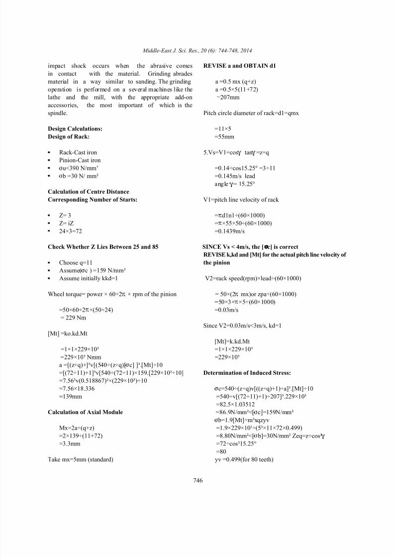
impact shock occurs when the abrasive comes REVISE a and OBTAIN d1
in contact with the material. Grinding abrades
material in a way similar to sanding. The grinding a =0.5 mx (q+z)
operation is performed on a several machines like the a =0.5×5(11+72)
lathe and the mill, with the appropriate add-on =207mmaccessories, the most important of which is the
spindle. Pitch circle diameter of rack=d1=qmx
Design Calculations: =11×5
Design of Rack: =55mm
Rack-Cast iron 5.Vs=V1÷cos tan =z÷q
Pinion-Cast iron
u<390 N/mm² =0.14÷cos15.25° =3÷11
b =30 N/ mm² =0.145m/s lead
Calculation of Centre Distance
Corresponding Number of Starts: V1=pitch line velocity of rack
Z= 3 = d1n1÷(60×1000)
Z= iZ = ×55×50÷(60×1000)
24×3=72 =0.1439m/s
Check Whether Z Lies Between 25 and 85 SINCE Vs < 4m/s, the [ c] is correct
Choose q=11 the pinion
Assume( c ) =159 N/mm²
Assume initially kkd=1 V2=rack speed(rpm)×lead÷(60×1000)
Wheel torque= power × 60÷2 × rpm of the pinion = 50×(2 mx)or zpa÷(60×1000)=50×3× ×5÷(60×1000)
=50×60÷2 ×(50÷24) =0.03m/s
= 229 Nm
[Mt] =ko.kd.Mt
=1×1×229×10³ =1×1×229×10³
=229×10³ Nmm =229×10³
a =[(z÷q)+]³v[(540÷(z÷q)[ c] ]².[Mt]÷10
=[(72÷11)+1]³v[540÷(72÷11)×159.[229×10³÷10] Determination of Induced Stress:
=7.56³v(0.518867)²×(229×10³)÷10
=7.56×18.336 c=540÷(z÷q)v[((z÷q)+1)÷a]³.[Mt]÷10=139mm =540÷v[(72÷11)+1)÷207]³.229×10³
Calculation of Axial Module =86.9N/mm²<[ c]=159N/mm²
Mx=2a÷(q+z) =1.9×229×10³÷(5³×11×72×0.499)
=2×139÷(11+72) =8.80N/mm²<[ b]=30N/mm² Zeq=z÷cos³
=3.3mm =72÷cos³15.25°
Take mx=5mm (standard) yv =0.499(for 80 teeth)
angle = 15.25°
REVISE k,kd and [Mt] for the actual pitch line velocity of
Since V2=0.03m/s<3m/s, kd=1
[Mt]=k.kd.Mt
=82.5×1.03512
b=1.9[Mt]÷m³xqzyv
=80

7/25/2019 Design and Fabrication of Rack and Pinion
http://slidepdf.com/reader/full/design-and-fabrication-of-rack-and-pinion 4/5
Middle-East J. Sci. Res., 20 (6): 744-748, 2014
747
Basic Dimensions: =370+(1.5×5)
Rack: =378mm
L =(12.5+0.09 Z)MX Root diameter of the pinion
=(12.5+(0.09×72)15 df2=(z-2)mx-2c=284mm
L1=L+35(grinding allowance) =(72-2)5-(2×0.3×5)
=284+38
=319 Specification of Rack:
Number of Threads on Rack Material- Cast iron
=L1÷ mx Cross section=58×25mm
=319÷( ×5) Teeth on the rack is adjusted for
=21 86mm
Actual Length of Rack Specification of Pinion:
=21× ×5 Material-Cast iron
=330mm Outside diameter=58mm
Pitch diameter of the rack=55mm Circular pitch=4.7mm
Tip diameter da=d1+2mx Pressure angle=21°
=55+(2×5=65 Dedendum=1.8m
Root diameter df1=d1-2mx-2c Fillet radius=0.45mm
=55-(2×5)-2×(0.3×5)
=42 Expected Load Can Handle:
Design of Pinion P=mgh÷t
Face Width of the Pinion
b =0.75 d1
=0.75×55 =38.4
=42 M=?
Pitch circle diameter of pinion,d2=zmx g =9.8
=72×5 m =P×t ÷gh
=360mm =(38.4×5)÷(9.81×0.45)
Tip diameter of the wheel,da2=(z+2)mx
=(72+2)×5
=370mm Therefore to conclude, we have designed and
Maximum pinion diameter de2=da2+1.5mx are done. Rack and pinion mechanism are introduced in
=347mm
Module=1.5mm
Pitch circle diameter=55mm
Module=1.5mm
Addendum=1.5mm
Circular tooth thickness=2.35mm
Clearance=0.375
The power getting in pinion after all reduction
t =5sec(assumed)
h =45cm(assumed)
=43.49kg(including rack weight)
CONCLUSION
fabricated Rack And Pinion Lift and further calculations

7/25/2019 Design and Fabrication of Rack and Pinion
http://slidepdf.com/reader/full/design-and-fabrication-of-rack-and-pinion 5/5
Middle-East J. Sci. Res., 20 (6): 744-748, 2014
748
lifting mechanism.Thus we came in to a contradiction that REFERENCES
the installation of a lift is not an easy task and high
installation cost. 1. Prabhu, T.J., 2007. Fundamentals of Machine Design.
As compared with the other lifting mechanism, rack 2. Rathan, S.S., 2004. Theory of Machines.
and pinion lift mechanism does not need any separate 3. Wikipedia.machine rooms. Well designed Rack and pinion lifts are 4. Bansal, R.K., 1999. Theory of machines.
more compact and saves effort and time. 5. Rajput, R.K., 2003. Automobile Engineering.
6. Garg, S.K., 1990. Workshop Technology.
7. GUPTA, J.K., 2000. Workshop Technology.