design and fabrication of i-cycle - ijeee · design and fabrication of i-cycle . s. v. pavan kumar...
TRANSCRIPT

Design and Fabrication of I-Cycle
S. V. Pavan Kumar Maddukuri EEE, TKR College of Engineering and Technology, Hyderabad, India
Email: [email protected]
Borla Srikanth ME, TKR College of Engineering and Technology, Hyderabad, India
Email: [email protected]
Abstract—This paper proposes a new concept in the electric
vehicle in the area of the renewable energy. An I-Cycle is a
self-balancing electric unicycle. Although a regular unicycle
is pedal-powered and is balanced by the skill of the rider,
the I-Cycle is powered by an electric motor and uses a
control system to balance in the roll direction. I-Cycle is
intended to be a fast and portable means of transportation
between public transport, home and office. Further-more,
with a learning time of thirty minutes, the I-Cycle brings
unicycling to the balance-challenged.
Index Terms—renewable energy, self-balancing, portable,
unicycling, centre of gravity (COG), gesture control, PD
controller
I. INTRODUCTION
Over the past twenty years, the unicycle has been the
subject of a diverse range of papers. Many of these
studies have been on a theoretical or educational basis
and have not involved building a test device.
Additionally, most tend to focus on emulating
autonomous (unmanned) unicycles rather than producing
a ride able device, which is the aim of the I-Cycle project.
There was limited evaluative literature available on
these designs, so a critical design review was performed
for the focus designs self-balancing unicycle (SBU) [1],
Trevor Blackwell’s Electric Unicycle [2] and the
Enicycle [3]. It is noteworthy that literature discussing
the dynamics of a ‘ballbot’ is used extensively through
this review. A ballbot is a self-balancing robot which
stabilises itself in two orthogonal planes on a ball. The
dynamics of the ballbot are relevant because the
assumption can be made that motion in the two planes of
the device are decoupled. Hence the dynamics for each of
these planes are applicable to the planar motion of the I-
Cycle.
The project aims at the design and construction of a
self-balancing unicycle, known as the I-Cycle. A Self-
balancing Unicycle is similar to a regular unicycle, but
rather than being controlled by the rider’s feet on the
pedals; sensors, microcontroller and a motor are used to
maintain stability in the direction of travel. Roll stability
is controlled by the rider through steering with the foot-
pegs. The rider can control the speed of travel by leaning
Manuscript received April 9, 2014; revised October 24, 2014.
forwards or backwards. In this sense, a Self-balancing
Unicycle could also be described as a one-wheeled Segue.
The finished I-Cycle has met all the core project goals.
The mechanical hardware was resilient throughout the
development process and only minor replacements to
exterior protective padding were required. The iterative
electrical and software development process coupled with
the monitoring of issues through the Failure Modes and
Effective Analysis (FMEA) resulted in a final device
which has a high degree of reliability, predictability and
safety. I-Cycle has attracted a significant level of
community and media attention, including exhibitions
and feature stories in print media, television and radio.
Thus in addition to successful development of a self-
balancing unicycle for urban use, the project has also
established the I-Cycle as an outstanding educative
device.
The scope of this project is to design a ride able
unicycle, primarily for transport. Therefore, the term
‘self-balancing unicycle’ is used to refer to a ride able
unicycle in which roll stability is provided by a control
system. This scope has led to a focus on four core values:
practicality, user safety, marketability, and education.
The idea of a practical unicycle, let alone a practical self-
balancing unicycle, is often met with incredulity. In the
public imagination, unicycles are comical devices
employed by clowns with juggling balls, and unicyclists
regularly endure such witty comments as, “lost a wheel,
mate?” [4]. This may well be an example of ‘tall poppy
syndrome’, as a unicycle is inherently difficult to learn
and thus people find it easier to ridicule the idea.
A unicycle, especially considered in light of today’s
commuter transport requirements, is in fact a practical
device. Compared with a bicycle, it is lighter, more
portable and considerably cheaper. Thus, a unicycle can
easily be transported in car boots, trams, trains, and even
in lifts to office cubicles. However, with the difficulty of
pitch balancing removed, a self-balancing unicycle is no
more difficult to ride than a bicycle, yet maintains many
of the benefits associated with a regular unicycle. The
addition of electric power means that increased distances
can be travelled with relative ease. Furthermore, a self-
balancing unicycle also improves on other self-balancing
scooters by offering better portability, lower cost, and a
heightened sense of freedom.
International Journal of Electronics and Electrical Engineering Vol. 3, No. 5, October 2015
©2015 Engineering and Technology Publishing 35910.12720/ijeee.3.5.359-364doi:
II. DESIGN AND IMPLEMENTATION
The development process includes an investigation of
existing designs which are then ranked with a decision
matrix. Following this is a discussion of the mechanical
design of components that were manufactured for the I-
Cycle. These include the fork and spindle assembly, the
main chassis, and the seat pole location. The design
process focused on achieving five key goals: ease of
manufacture, optimal centre of gravity (CoG), durability,
design flexibility and aesthetics. To achieve these goals
the design process was an iterative process involving
modelling the I-Cycle, CoG analysis and a static
structural analysis of the critical components to
determine component dimensions and CoG of the I-Cycle
inclusive with rider.
A. Fork
The fork design [5] addresses the major issue that is,
asymmetrical motor rim combination. The wheel has an
offset centre plane which is required to be aligned with
the centre plane of the spindle. Failure to realign these
planes would result in the tyre being in a plane that is not
central to the rider. As such, the fork legs are offset as
shown in Fig. 1. The forks also incorporate locations to
attach rubber bump stops to the ends of the horizontal
section to reduce damage to the I-Cycle in case of
collision.
Figure 1. Fork pro-e model
B. Seat Installation and Mass Distribution
The weight bias of the I-Cycle is a critical requirement
of the design to allow the I-Cycle to balance in an upright
position. To determine the desired CoG, both the I-Cycle
and rider’s combined CoG were required to be located
vertically over the hub motor’s axle line to ensure that the
balance angle of the I-Cycle was vertical [6]. Pro-
Engineer creo 2.0 (ProE) was used in calculating the
centre of gravity of the I-Cycle. The connection between
the seat and seat post is adjustable in the angular and
longitudinal directions as shown in Fig. 2.
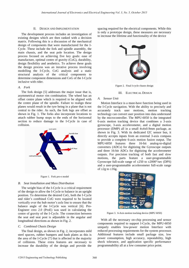
C. Combined Chasis Design
The final design, as shown in Fig. 2, incorporates mild
steel spacers, rubber bumpers and bash plates as this is
the area of the I-Cycle [7] that is affected in the majority
of collisions. These extra features are necessary to
increase the durability of the design and provide the
spacing required for the electrical components. While this
is only a prototype design, these measures are necessary
to increase the lifetime and functionality of the device
Figure 2. Final I-cycle chases design
III. ELECTRICAL DESIGN
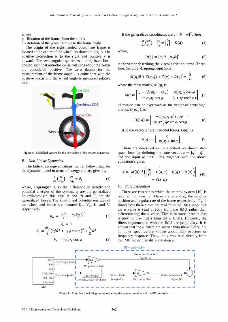
A. Sensor Unit
Motion Interface is a must-have function being used in
the I-Cycle navigation. With the ability to precisely and
accurately track user motions, motion tracking
technology can convert user position into data understand
by the microcontroller. The MPU-6050 is the integrated
6-axis motion tracking device that combines a 3-axis
gyroscope, 3-axis accelerometer, and a digital motion
processor (DMP) all in a small 4x4x0.9mm package, as
shown in Fig. 3. With its dedicated I2C sensor bus, it
directly accepts inputs from an external 3-axis compass
to provide a complete 6-axis motion fusion output. The
MPU-6050 features three 16-bit analog-to-digital
converters (ADCs) for digitizing the Gyroscope outputs
and three 16-bit ADCs for digitizing the accelerometer
outputs. For precision tracking of both fast and slow
motions, the parts feature a user-programmable
Gyroscope full-scale range of ±250 to ±2000°/sec (DPS)
and a user-programmable accelerometer full-scale range
of ±2g to ±16g.
Figure 3. 6-Axis motion tracking device (MPU 6050)
With all the necessary on-chip processing and sensor
components required to support I-Cycle, the MPU-6050
uniquely enables low-power motion Interface with
reduced processing requirements for the system processor.
Additional features include small package size, low
power consumption, high accuracy, repeatability, high
shock tolerance, and application specific performance
programmability all at a low consumer price point.
International Journal of Electronics and Electrical Engineering Vol. 3, No. 5, October 2015
©2015 Engineering and Technology Publishing 360

B. Control Unit
The control unit is brain of I-Cycle. Arduino Uno
along with ATMEGA328, as shown Fig. 4 constitutes to
control unit. In order to stabilise the rider in the centre of
plain the control unit analyse [8], [9] the data from sensor
unit and give signal to the motor driver. The main reason
behind choosing this microcontroller is its feasibility to
program when in operation and inbuilt debugger.
Figure 4. Arduino uno
C. Motor Driver
In this project an H-bridge made of two TIP147 and
two TIP142 as shown in Fig. 5 was used. Based on the
signal given by the sensor unit the control unit trigger the
transistor Q1 and Q2 for forward direction and Q3 and
Q4 for reverse direction of the motor. The proposed
driver is capable of driving a motor that runs at 24V and
40Amps.
Figure 5. H-Bridge driver circuit
D. Motor
The designed I-Cycle was capable of driving a load of
120kgs and runs on battery bank. So, to meet the
requirements a 300W, 24V brushed DC motor [10] as
shown in Fig. 6 was chosen. The reason choosing
brushed motor is its high efficiency and easy control.
Figure 6. 300W, 24V brushed DC motor
IV. IMPLEMENTATION
The final I-Cycle product is fabricated by fixing the
sensor and control units to the mechanical chases, shown
Fig. 7. As explained above, Motion Interface is a must-
have function being used in the I-Cycle navigation. With
the ability to precisely and accurately track user motions,
motion tracking technology can convert user position into
data understand by the microcontroller, which analyse the
data and gives signal to motor driver which in turn
control the motion of the motor there by stabilizes the
rider position in the centre plane [11].
Figure 7. Fully fabricated I-cycle
V. SYSTEM MODELLING AND CONTROL
In this section, the non-linear dynamics of the I-Cycle
system are derived. The assumptions used in this
derivation and the definition of terms are both outlined
below. Following this, the system dynamics are derived
and a relationship between the electrical supply current
and the torque produced by the motor is established.
A. Dynamics of the 2 Degree of Freedom (DOF) System
The dynamics of the I-Cycle are developed from the
inverted pendulum model used extensively in Driver
[12]-[14] to include the translational motion of the
pendulum. However, these derivations are inconsistent
with regards to coordinate frames and non-conservative
forces. Therefore an extensive verification process was
based on the dynamics derived in [15], [16] through
coordinate transforms, verified with the papers discussed
above. The following assumptions have been made in the
derivation of the dynamics, with reference to the
coordinate system and directions.
Motion is restricted to xy-plane
A rigid cylinder is used to model the chassis and a
vertically orientated thin solid disk used to model
the wheel
Coulomb friction arising from the bearings and
tyre-ground contact is neglected, and hence only
viscous friction is considered
The motor is controlled via an intelligent
controller in `current mode' such that the input
into the plant is a torque command
There is no slip between the tyre and the ground
The model is defined in terms of coordinates φ
and θ,
International Journal of Electronics and Electrical Engineering Vol. 3, No. 5, October 2015
©2015 Engineering and Technology Publishing 361
International Journal of Electronics and Electrical Engineering Vol. 3, No. 5, October 2015
©2015 Engineering and Technology Publishing 362
where
φ - Rotation of the frame about the z-axis
θ - Rotation of the wheel relative to the frame angle
The origin of the right-handed coordinate frame is
located at the centre of the wheel, as shown in Fig. 8. The
positive x-direction is to the right and positive y is
upward. The two angular quantities, - and, have been
chosen such that anti-clockwise rotations about the z-axis
are considered positive. The zero datum for the
measurement of the frame angle - is coincident with the
positive y-axis and the wheel angle is measured relative
to φ.
Figure 8. Modelled system for the derivation of the system dynamics
B. Non-Linear Dynamics
The Euler-Lagrange equations, written below, describe
the dynamic model in terms of energy and are given by
𝑑
𝑑𝑥(
𝜕𝐿
𝜕𝑞𝑖) −
𝜕𝐿
𝜕𝑞𝑖= 𝐹𝑖 (1)
where, Lagrangian L is the difference in kinetic and
potential energies of the system, qi are the generalized
co-ordinates (in this case φ and θ) and Fi are the
generalized forces. The kinetic and potential energies of
the wheel and frame are denoted Kw, Vw, Kf and Vf
respectively
𝐾𝑤 = 𝐼𝑤��2
2+
𝑚𝑤(𝑟𝑤��)2
2 (2)
𝑉𝑤 = 0
𝐾𝑓 =𝑚𝑓
2(𝑟𝑤
2��2 + 𝑟𝑓�� cos 𝜑)2
+𝐼𝑓
2��2
𝑉𝑓 = 𝑚𝑓𝑔𝑟𝑓 cos 𝜑 (3)
If the generalised coordinates are q= [𝜃 𝜑]𝑇 , 𝑡ℎ𝑒𝑛
𝑑
𝑑𝑡(
𝜕𝐿
𝜕��) −
𝜕𝐿
𝜕𝑞= [
0𝜏
] − 𝐷(��) (4)
where,
𝐷(��) = [𝜇𝜃�� 𝜇𝜑��]𝑇 (5)
is the vector describing the viscous friction terms. There-
fore, the Euler-Lagrange equations
𝑀(𝑞)�� + 𝐶(𝑞, ��) + 𝐺(𝑞) + 𝐷(𝑞) = [0𝑇
] (6)
where the mass matrix, M(q), is
M(q)= [𝐼𝑤 + 𝑟𝑤
2(𝑚𝑓 + 𝑚𝑤) 𝑚𝑓𝑟𝑤𝑟𝑓 cos 𝜑
𝑚𝑓𝑟𝑤𝑟𝑓 cos 𝜑 𝐼𝑓 + 𝑟𝑓2 cos2 𝜑𝑥
] (7)
of motion can be expressed as the vector of centrifugal
effects, 𝐶(��, 𝑞), is
𝐶(��, 𝑞) = [−𝑚𝑓𝑟𝑤𝑟𝑓 φ2sin 𝜑
−𝑚𝑓𝑟2
𝑓φ2sin 𝜑 cos 𝜑
] (8)
And the vector of gravitational forces, G(q), is
𝐺(𝑞) = [0
−𝑚𝑓𝑟𝑓 g sin 𝜑] (9)
These are described in the standard non-linear state
space form by defining the state vector, 𝑥 = [𝑞𝑇 ��𝑇], and the input as u=T. This, together with the above
equitation’s gives
𝑥 = [𝑀(𝑞)−1 ([0𝑇
] − 𝐶(𝑞, ��) − 𝐺(𝑞) − 𝐷(��))]
= 𝑓(𝑥, 𝑢)
(10)
C. State Estimation
There are two states which the control system [10] is
required to measure. These are φ and φ, the angular
position and angular rate of the frame respectively. Fig. 9
shows how these states are read from the IMU. Note that
the φ value is read directly from the IMU rather than
differentiating the φ value. This is because there is less
latency in the- filters than the φ filters. However, the
filters implemented with the IMU are proprietary. It is
known that the φ filters are slower than the φ filters, but
no other specifics are known about their structure or
frequency response. Thus, the φ was read directly from
the IMU rather than differentiating φ.
Figure 9. Simulink block diagram representing the state estimation and the PD controller

International Journal of Electronics and Electrical Engineering Vol. 3, No. 5, October 2015
©2015 Engineering and Technology Publishing 363
D. PD Controller
The control strategy employed here uses a standard
proportional-derivative (PD) controller. The
implementation of this controller can be seen in Fig. 7.
The reason for why a PID controller was not used is that
a human naturally acts to reduce the steady state error
and the addition of integral control can degrade the
performance of the controlled response [4]. A low pass
filter was used on the derivative control term to make the
controller proper and to filter out noise from the sensors
in the physical system. The parameters of the tuned
control system are presented in Table I and II. The
transfer function for the designed PD controller is
presented in (1). Note that strictly speaking, the system
actually consists of two distinct transfer functions, one
for φ and one for φ, as different sensors are used for each
state. Nevertheless, this is a PD controller and (1)
represents the effective transfer function with the two
feedback terms combined.
TABLE I. DESCRIPTION AND VALUES OF VARIOUS SYMBOLS USED IN
THE CALCULATIONS
Symbol Value Description
𝑟𝑤 0.203 m Radius of the wheel
𝑟𝑓 0.3 m Distance to the centre of mass of the frame from the origin
𝑚𝑤 7.0 kg Mass of the wheel
𝑚𝑓 15.0 kg Mass of the frame
𝐼𝑓 0.45 kgm2 Moment of inertia of the frame w.r.t.its centre of mass
𝐼𝑤 0.145
kgm2
Moment of inertia of the wheel w.r.t.
its own centre of mass
𝜇∅ 0.08 Nm/(rad/s)
Coefficient of rotational viscous friction(bearing friction and motor losses)
𝜇𝜃 0.05
Nm/(rad/s)
Coefficient of translational viscous
friction (rolling resistance)
𝑘𝑟 1.64 Nm/A Motor torque constant
g 9.81 m/s2 Gravitational acceleration
TABLE II. DESCRIPTION OF VARIOUS SYMBOLS USED IN THE
CALCULATIONS
Symbol Description
𝜃 Angular position of the wheel with respect to the frame (anti-clockwise positive)
�� Angular velocity of the wheel
�� Angular acceleration of the wheel
𝜑 Angular position of the frame with
respect to the positive y-axis
�� Angular velocity of the frame (anti-
clockwise positive)
�� Angular acceleration of the frame
τ Torque applied by the motor, excluding
friction
i Motor supply current
E. Experimental Results of the Closed Loop PD
Controller
The above methodology was then applied to the
physical I-Cycle, shown in Fig. 7. The results can be seen
in Fig. 10 and Fig. 11.
VI. CONCLUSION AND FUTURE WORK
In this paper the dynamics of the unicycle were
derived and presented. Future work includes the
development of a model based non-linear controller and a
back stepping controller. These control strategies will be
compared and benchmarked, with the optimal strategy
being implemented into the I-Cycle design. A higher
capacity motor controller shall also be integrated into the
system to alleviate the high tendency to saturate. Another
planned development is the addition of active
stabilization in the roll direction. This will use either a
reaction wheel or a control moment gyroscope and this
actuator will allow the I-Cycle to be a completely self-
balancing electric unicycle.
Figure 10. Closed loop response of the constrained physical I-cycle system when rotated to 20 degrees and released.
Figure 11. Closed loop response of the constrained physical I-cycle system when rotated to 5 degrees and released
REFERENCES
[1] (2012). One wheel, infinite fun. [Online]. Available:http://focusdesigns.com/sbuv3/
[2] (2013). Trevor-Blackwell. [Online]. Available:
http://focusdesigns.com/tag/trevor-blackwell/[3] (2013). Prototype of enicycle. [Online]. Available:
http://www.enicycle.com/prototype.html
[4] (Dec. 27, 2009). Unicycling. [Online]. Available:http://bigi.org.uk/blog/2007/12/21/sam-shusters-hormonal-
unicycling-hack/[5] K. D. Do and J. Pan, “Nonlinear formation control of unicycle-
type mobile robots,” Robotics and Autonomous Systems, vol. 55,
no. 3, pp. 191-204, 2007[6] Y. Naveh, P. Z. Bar-Yoseph, and Y. Halevi, “Nonlinear modeling
and control of a unicycle,” Dynamics and Control, vol. 9, no. 4,
pp. 279-296, 1999.[7] D. Voth, “Segway to the future [autonomous mobile robot],”
IEEE Intelligent Systems, vol. 20, pp. 5-8, 2005.
[8] C. Huang, “The development of self-balancing controller for one-wheeled vehicles,” Engineering, vol. 2, no. 4, pp. 212-219, 2010.
[9] R. O. Ambrose, R. T. Savely, S. M. Goza, P. Strawser, M. A.
Diftler, I. Spain, and N. Radford, “Mobile manipulation using NASA’s robonaut,” in Proc. IEEE International Conference on
Robotics and Automation, New Orleans, 2004, pp. 2104-2109.
International Journal of Electronics and Electrical Engineering Vol. 3, No. 5, October 2015
©2015 Engineering and Technology Publishing 364
[10] F. Grasser, A. D’Arrigo, S. Colombi, and A. C. Ruffer, “JOE: A
mobile, inverted pendulum,” IEEE Transactions on Industrial
Electronics, vol. 49, no. 1, pp. 107-114, 2002.
[11] M. A. Clark, J. B. Field, S. G. McMahon, and P. S. Philps,“EDGAR: A self-balancing scooter,” Honours thesis, The
University of Adelaide, 2005.
[12] K. Pathak, J. Franch, and S. K. Agrawal, “Velocity and position control of a wheeled inverted pendulum by partial feedback
linearization,” IEEE Transactions on Robotics, vol. 21, no. 3, pp.
505-513, 2005.
[13] H. Tirmant, M. Baloh, L. Vermeiren, T. M. Guerra, and M. Parent,
“B2, an alternative two wheeled vehicle for an automated urban
transportation system,” in Proc. IEEE Intelligent Vehicles
Symposium, 2002, vol. 2, pp. 594-603.
[14] U. Nagarajan, A. Mampetta, G. A. Kantor, and R. L. Hollis, “State
transition, balancing, station keeping, and yaw control for a
dynamically stable single spherical wheel mobile robot,” in Proc.
IEEE International Conference on Robotics and Automation, May
2009, pp. 998-1003.[15] K. Hofer, “Observer-Based drive-control for self-balanced
vehicles,” in Proc. IEEE/IECON 32nd Annual Conference on
Industrial Electronics, 2006, pp. 3951-3956.[16] R. Nakajima, T. Tsubouchi, S. Yuta, and E. Koyanagi, “A
development of a new mechanism of an autonomous unicycle,” in
Proc. 1997 IEEE/RSJ Inter-National Conference on Intelligent Robots and Systems, 1997, vol. 2, pp. 906-912.
S. V. Pavan Kumar Maddukuri, Assistant
Professor, TKR College of Engineering &
Technology. M.Sc (Engg) from University of
Greenwich, England. He has completed his B.Tech from JNTUK, Kakinada. He has
published 2 International conference papers
and 4 International Journals. His Area of interest is Applications of Power Electronics to
Electrical Machines & Renewable Energy
Sources. He has more than 2 years of teaching experience. He is a member of IAENG and IACSIT.
Borla Srikanth is B.Tech Graduate from TKR
College of Engineering and technology. His
are of interest includes Composite materials, Robotics, designing and automation. He is
member of SAE-I.