design and fabrication of driver …umpir.ump.edu.my/8575/1/cd7993_@_48.pdf · during this phase,...
TRANSCRIPT

DESIGN AND FABRICATION OF DRIVER COMPARTMENT OF AN ELECTRIC
GO KART
SYAZANA BINTI NOORSHIRWAN
Thesis submitted in fulfillment of the requirements
for the award of the Diploma in Mechanical Engineering
Faculty of Mechanical Engineering
UNIVERSITI MALAYSIA PAHANG
DECEMBER 2012

vi
ABSTRACT
The objective of this project is to design and fabricate driver compartment of an electric
go kart. The main problem is the comfort of the drivers. The scopes identified must
consist of cushioned seat and adjustable mechanism. The first stage is did some
literature review about the existing go-kart and adjustable mechanism. Current model of
go-kart consists of plastic and fixed seat. Hence, this project is to modify the current
model of go-kart into a model that is comfort for the user where the driver compartment
will be installed with an adjustable and cushioned seat. Follow up with some designing
and sketching. During this phase, three designs had been sketch to be as the design
concepts. As for each design have their advantages and disadvantages. After done with
design and sketch, conceptual process is done and design 3 has been chosen because
this design is more advantageous than other two designs. Design 3 is small and the
adjustable mechanism is easier to handle. Some modification is done on design 3 where,
seat mounting is being added for placing the cushioned seat. Next stage after finalize the
design, the project is continued with fabrication process. The adjustable is modified into
smaller width according to the design dimension where, both side of the adjustable
mechanism is connected with a small angle bar in the middle by welding. While for the
seat mounting, a square hollow beam is used. The hollow beam is measured and marked
with the correct length and then being cut into the desired length. Drilling is done on the
hollow beam for assemble the seat on the seat mount. After that, the square hollow
beam is welded on the adjustable mechanism according to the drawing. Finish with the
welding, finishing process is done where for this project white paint is used and then the
cushioned is assembled with the product. Thus, by finishing this project, the objective of
the project is achieved

vii
ABSTRAK
Projek ini bertujuan untuk mereka dan menghasilkan ruang pemandu bagi go-kart
elektrik. Masalah utama yang dihadapi adalah keselesaan pemandu ketika memandu.
Projek ini perlu merangkumi skop-skop berikut, mempunyai tempat duduk berkusyen
dan mempunyai mekanism boleh laras bagi menggerakkan kedudukan tempat duduk ke
depan dan kebelakang. Langkah pertama yang dilakukan adalah malakukan sedikit
kajian mengenai model go-kart yang sedia ada dan mengenai mekanism boleh laras.
Model sedia ada mempunyai tempat duduk plastic dan kedudukan yang tetap. Oleh itu,
projek ini bertujuan untuk mengubahsuaikan model sedia ada menjadi model yang
selesa untuk pemandu di mana bahagian pemandu akan dipasang dengan tempat duduk
berkusyen and boleh dilaras. Seterusnya, fasa mereka dan melakar di mana tiga rekaan
dilakar untuk dijadikan sebagai konsep reka bentuk. Setiap rekaan mempunyai
kelebihan dan kekurangan masing-masing. Selesai dengan fasa mereka dan melakar,
proses pemilihan konsep dilakukan dan reka bentuk 3 dipilih berdasarkan kelebihan
rekaan ini iaitu rekaan ini lebih kecil dan mekanism pelarasannya lebih mudah
digunakan berbanding dengan dua reka bentuk lain. Sedikit pengubahsuaian dilakukan
ke atas rekaan 3 bagi memudahkan pemasangan tempat duduk akhir nanti. Selepas
memilih konsep rekaan yang terbaik, fasa pembuatan dijalankan. Mekanism pelarasan
diubahsuai mengikut lebar dimensi lukisan dan disambung oleh „angle bar‟ bersaiz kecil
melalui proses kimpalan. Bagi tempat pelekap kerusi, „square hollow beam‟ digunakan.
Bahan tersebut diukur dan ditanda mengikut ukuran yang dikehendaki dan kemudiannya
dipotong mengikut ukuran yang ditanda. Proses penggerudian dilakukan ke atas „square
hollow beam‟ untuk pemasangan tempat duduk kemudian. Selepas itu, bahan yang
sudah digerudi itu dikimpal di atas mekanism pelarasan mengikut lukisan yang telah
dilukis. Akhir sekali, produk yg sudah disiapkan di cat menggunakan cat putih sebagai
kemasan sebelum tempat duduk dipasang. Dengan menyiapkan projek ini, objektif
projek in tercapai.

viii
TABLE OF CONTENTS
Page
SUPERVISOR’S DECLARATION ii
STUDENT’S DECLARATION iii
DEDICATION iv
ACKNOWLEDGEMENTS V
ABSTRACT vi
ABSTRAK vii
TABLE OF CONTENTS viii
LIST OF TABLES xi
LIST OF FIGURES xi
LIST OF ABBREVIATIONS xii
CHAPTER 1 INTRODUCTION
1.1 Introduction 1
1.2 Project Background 1
1.3 Problem Statement 2
1.4 Objective of Project 2
1.5 Scopes of Project 3
1.6 Project Planning 3
1.7 Thesis Outline 7
CHAPTER 2 LITERATURE REVIEW
2.1 Introduction 9
2.2 Current Design of Go-kart 9
2.3 Adjustable mechanism 11

ix
CHAPTER 3 METHODOLOGY
3.1 Introduction 15
3.2 Design 15
3.2.1 Design 1 16
3.2.2 Design 2 17
3.2.3 Design 3 18
3.3 Design comparison 18
3.4 Final concept 19
CHAPTER 4 FABRICATION PROCESS
4.1 Introduction
21
4.2 Fabrication Process 21
4.2.1 Measuring and Marking 22
4.2.2 Cutting 23
4.2.3 Drilling 23
4.2.4 Welding 24
4.2.5 Grinding 25
4.2.6 Fastening 25
4.2.7 Finishing 27
4.3 Safety precaution during welding process 27
4.3.1 General 27
CHAPTER 5 RESULT AND DISCUSSION
5.1 Introduction 29
5.2 Final Product 29
5.3 Problem encounter 31
CHAPTER 6 CONCLUSION AND FUTURE RECOMMENDATTION
6.1 Introduction 32
6.2 Conclusion 32
6.3 Recommendation 32

x
REFERENCES 34
APPENDICES
A Designs Drawing 35
B Figures of Machines / Tools 44
C Figures of Safety Tools /Wears 47

xi
LIST OF TABLES
Tables No. Title Page
1.2 Project Gantt chart 6
3.1 Design comparison of the three proposed designs 19
LIST OF FIGURES
Figure No. Title Page
1.1 Project flow chart 5
2.1 First Current go-kart design 10
2.2 Second Current go-kart design 10
2.3 Third Current go-kart design 11
2.4 Image of the Seat Track 12
2.5 Seat Track Mechanism 12
2.6 Simulation on the Seat Track 13
2.7 Simulation on the part of the Seat Track 13
3.1 Design 1 16
3.2 Design 2 17
3.3 Design 3 18
3.4 Final Design after Modification 20
4.1 Measuring tape 22
4.2 Scriber 22
4.3 Cutting process 23
4.4 Drilling process 24

xii
4.5 Welding process 24
4.6 Grinding process 25
4.7 Fastening process 26
4.8 Type of fastener used 26
4.9 Finishing process 27
5.1 Adjustable mechanism 29
5.2 Final product after grinding process 30
5.3 Final product after finishing process 30
5.4 assembled final product 30
LIST OF ABBREVIATIONS
PPE Personal Protective Equipment
SMAW Shielded metal arc welding
UMP University Malaysia Pahang

CHAPTER 1
INTRODUCTION
1.1 INTRODUCTION
This chapter will explains about the project background, project objective,
project scope and the project flow that has been conducted throughout the semester.
Besides that, in this chapter also consist of flow chart and Gantt chart of the project
which explains the overall procedures and the times being distributed to finish this
project.
1.2 PROJECT BACKGROUND
Art Ingels developed the first go-kart in 1956 in Los Angeles, California. Ingels
was a race car builder for Kurtis Kraft, a race car designer and developer. In 1958, Go
Kart Manufacturing Co. Inc. became the first company to manufacture and to distribute
go-karts. In 1959, McCullough was the first company to manufacture go-kart engines.
In 1957, the International Kart Federation or IFK, began establishing the rules for go-
kart competitions. By 1960, go-kart racing began to appear at local tracks across the
United States. Throughout the decade, new go-kart tracks surfaced in many different
cities and states. Go-karts continued to evolve thanks to the innovation of builders and
designers. Go-karts originally were simple and straight forward machines. Over the
course of the last five decades, they emerged as machines involving sophisticated and
advanced assembling. Despite the advancement in styles, go-kart racing remains the
least expensive form of professional auto racing. While go-karts originated from United
States, interest in go-kart racing began to pique in other countries and continents
throughout the worlds, most notably Europe and Australia. For example, in 1966, the

2
Australian Karting Association or AKA, was formed to promote go-kart racing in
Australia. The Motor Sports Association or MSA, became the governing body for go-
kart racing in United Kingdom in 2000s. in 1971, the World Karting Association or
WKA, was formed as a non-profit company supporting the developing sport of go-kart
racing. The organization rapidly progressed to become the largest go-kart racing
sanctioning body in the United States, with more than 10,000 participants.
Racing go-karts have evolved over the past 50 years to become one of the most
competitive forms of motor racing in the United States. Kart racing has been a “stepping
stone” for many drivers working their way up the professional ladder in NASCAR,
Formula 1, and the Indy Racing League. Drivers like Tony Steward, Danica Patrick,
Michael Schumacher and Sarah Fisher each got his or her start in this less expensive but
adrenaline pumping form of motorsports racing. As a recreational activity, karting can
appeal to just about anyone. From age 5 to 75, racing go-karts have become popular all
over the world with people looking for an exciting way of having fun. In fact, many
amusement parks have added rental racing go-kart (called concession karts) that use
detuned 4-stroke go-kart engines for a milder experience.
1.3 PROBLEM STATEMENT
The problem statements of this project are:
i) To improve the skills and knowledge of Mechanical Engineering students in
designing and importance of project developing go-kart
ii) The comfort of the go-kart users
1.4 OBJECTIVES OF THE PROJECT
The objectives of this project are:
i) To design the driver‟s compartment in a go-kart
ii) To fabricate the driver‟s compartment in a go kart

3
1.5 SCOPES OF THE PROJECT
This project will be limited within the following aspects which are:
i) A conceptual design by using solid works
ii) A seat with an adjustable mechanism
iii) A cushioned seat for the go-kart
iv) The floor dimension on the chassis is 400mm x300mm
1.6 PROJECT PLANNING
Figure 1.1 shows the flow chart of the whole Final Year Project. This project
started with meeting the supervisor to discuss about problem statement, objective and
scopes the project title given and managed the schedule of weekly meeting. The meeting
was set up on every Wednesday. Then followed with made some research about the
project and literature review where it took about seven weeks to be done.
Then followed with sketch and design phase where few sketches need to be
done as the design concepts. Each design concepts then need to be analyzed t and chose
as the final design. When final design is chose, propose the design to the supervisor.
After the approval of the supervisor, the design is converted to the 3D drawing using
Solid Works software.
Finished with all the sketches and design phase, the preparation of mid-
presentation was next. This task took about a week to be done. Few days before
presenting, the slides presentation will be presented to the supervisor for some
comments and corrections to improve the slides. With the knowledge attained and
instilled in the design phase, the first half progress of the project was presented to the
three panels of judges.
After mid-presentation phase, some survey is done for the materials needed for
the project. There were only few materials needed in order to fabricate the adjustable

4
mechanism and to find the cushioned seat. Other needed materials were well-prepared
by the university.
Fabrications phase started with the basic fabrication process like measuring,
cutting and the joining process. For this project joining processes involved were
welding and fastening.
The last task will be the final presentation and report writing that need to be
accomplished before the semester break. The final presentation then again will be
presented in front of the assigned panels. A draft report was submitted to the supervisor
to be point out the flaws. Corrections were done and the final report was handed as the
completion of the Final Year Project.

5
NO
YES
Figure 1.1: Project flow chart
START
Project Discussion
Final
Design
END
Literature Review
Sketch and Design
Finalize Design
First Presentation
Material Selection
Fabrication
Final Presentation
Final Report

6
Table 1.2: project Gantt chart
By referring the Gantt chart in table 1.2, this final year project start with some
introduction or briefing discussing about the objective, scope and identify the problem
for the project. Then, started do some research and literature review from the internet
and some reading that related to this project. All of this literature review took about nine
weeks to be done.
While doing the research, sketching design concepts is needed. However, the
actual duration for the concept design is longer than the planning duration due to some
difficulties to decide the concept designs. The sketch and design took about three weeks
to finish. Finalize design done on the next week.
WEEK
ACTIVITIES 1 2 3 4 5 6 7 8 9 10 11 12 13 14
PROJECT
DISCUSSION PLAN
ACTUAL MEETING
WITH
SUPERVISOR
PLAN
ACTUAL SKETCH AND
DESIGN
PLAN
ACTUAL FINALIZE
DESIGN
PLAN
ACTUAL FIRST
PRESENTATION
SLIDE
PLAN
ACTUAL FIRST
PRESENTATION
PLAN
ACTUAL FABRICATION PLAN
ACTUAL FINAL
PRESENTATION
SLIDE
PLAN
ACTUAL FINAL
PRESENTATION
PLAN
ACTUAL FINAL REPORT PLAN
ACTUAL

7
The duration for the fabrication process also is longer than the planning schedule
due to lack of tools facilities in the workshop. Since the numbers of the instrument and
tools are few thus, in order to finish the project need to take turn to use the facilities.
Other than that, machine problems also one of the factors the time for fabrication was
extended.
Lastly, after finish with fabrication and presentation, the report writing needed to
be submitted. This task took about a week to be done. The report was done based on
UMP thesis format and also guidance from the supervisor. all tasks scheduled took
about fourteen week to finish
1.7 THESIS OUTLINE
In Chapter 1, it would explain about problem identifications, objectives, scopes,
flow charts and Gantt chart of the project. In this chapter also contain the planned
direction of the Final Year Project.
In Chapter 2, it will go through the literature review of the go-kart driver‟s
compartment. This chapter will discuss about the existing model of go-kart‟s driving
compartment and the adjustable mechanism of the car that will be installed later in the
go-kart.
In Chapter 3, it will explain about the design concepts and the selection of the
final design of the project. This chapter will discuss more about the concept that has
been sketched out and the selection done to fabricate the go-kart driving compartment.
In Chapter 4, would go through the fabrication process of the selected design,
the tools, and the machines used for fabricating will be discussed.

8
In Chapter 5, will be focus about detail on the final product that had been
fabricated. There will be explanation about the fabricated product and will be shown in
this chapter. The result and discussion also will be included in this chapter.
In Chapter 6, will be containing the conclusion of the project. Also some
recommendation will be included in this chapter for improving the product.

CHAPTER 2
LITERATURE REVIEW
2.1 INTRODUCTION
This chapter will discuss about the literature review about the current go-kart
design. In this chapter, the explaination will be focused on the go-kart driver
compartment instead of the whole go-kart. This chapter also will be included the basic
explaination about the seat track mechanism (adjustable).
2.2 CURRENT DESIGN OF GO-KART
Go-kart is a small car that use for recreational and competition purpose hence
the design need to be convinience and user-friendly for all drivers. After done some
research, there are lots of go-kart design in the market. However, some or can be said
that all of the go-kart design using plastic seat and the seat is fixed. Figure 2.1, Figure
2.2 and Figure 2.3 shows different designs but with same inner part.

10
Figure 2.1 first current design
Source: http://chfourstar.en.made-in-china.com
Figure 2.2 second current design
Source: http://www.ceet.niu.edu
11
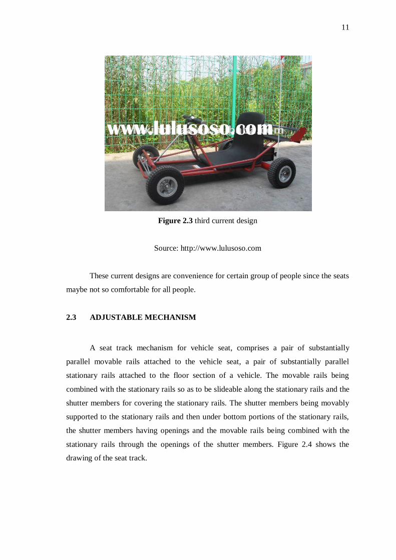
Figure 2.3 third current design
Source: http://www.lulusoso.com
These current designs are convenience for certain group of people since the seats
maybe not so comfortable for all people.
2.3 ADJUSTABLE MECHANISM
A seat track mechanism for vehicle seat, comprises a pair of substantially
parallel movable rails attached to the vehicle seat, a pair of substantially parallel
stationary rails attached to the floor section of a vehicle. The movable rails being
combined with the stationary rails so as to be slideable along the stationary rails and the
shutter members for covering the stationary rails. The shutter members being movably
supported to the stationary rails and then under bottom portions of the stationary rails,
the shutter members having openings and the movable rails being combined with the
stationary rails through the openings of the shutter members. Figure 2.4 shows the
drawing of the seat track.

12
Figure 2.4 the image of the seat track
Source: http://www.skidmore.edu
Figure 2.5 seat track mechanism
Source: http://www.bremarauto.com

13
Figure 2.6 Simulation on the seat track
Source: http://www.bremarauto.com
Figure 2.7 Simulation on part of the seat track
Source: http://www.bremarauto.com
Figure 2.5 shows the mechanism of the seat track. While Figure 2.6 and Figure
2.7 shows the adjustment mechanism of an automotive seat was simulated to calculate
various parameters such as torque required at the height adjustment handwheels for
different occupant loads, and the range of motion of the occupant‟s hip joint. The
analysis was also used to determine loads between various components and to calculate
stresses in the leaf return spring. MBD was the ideal tool of choice for this stress

14
analysis, as it provide accurate input loads without having to make any simplifying
assumptions to represent the loading.

CHAPTER 3
PROJECT METHODOLOGY
3.1 INTRODUCTION
In this chapter will explain three design concepts for the driver compartment of
the go-kart based on the scopes stated earlier. In this chapter also will discuss about the
advantages and disadvantages of the design concepts and explanation in order to select
the best design concept from the three designs to be fabricated. It also included the three
designs comparison using selection criteria that are considered the best for the go-kart.
3.2 DESIGN
As for this project, the driver compartment is focused on the sitting part of the
go-kart hence the design will lead to the design of the adjustable mechanism. Therefore,
the aspect that must be considered in designing is the operating mechanism, weight and
ease of design. Finally, the design of the system should be easy to fabricate and
assemble in accordance with the drawing.

16
3.2.1 Design 1
Figure 3.1 shows the isometric view of design 1. The advantages of this design
are stable and adjustable. The disadvantages are bulky, the adjustable mechanism is
hard to use, there are many small parts and no seat mount.
Figure 3.1 design 1