design and fabrication of a single-phase 1kva transformer ... · project uses ic lm358 is used as a...
TRANSCRIPT

International Research Journal of Engineering and Technology (IRJET) e-ISSN: 2395-0056
© 2018, IRJET | Impact Factor value: 6.171 | ISO 9001:2008 Certified Journal | Page 679
Design and fabrication of a Single-phase 1KVA Transformer with
automatic cooling system
Rahul Turkar1, Rahul Shahare2, Prashant Sidam3, Vijay Giradkar4, Avinash Patil5, Priya Sarode6
Department of Electrical Engineering, Nagpur Institute of Technology, Nagpur(441501), India. -----------------------------------------------------------------------***------------------------------------------------------------------------------- Abstract: This paper presents a method for the design of shell type, single phase distribution transformers to obtain the manufacturing specifications .This transformer have two output voltages it convert from 230V to 115V and 120V. There are without providing any tapping on the transformer. Here is a simple temperature sensor Circuit are use to sensing the temperature with the help of including temperature sensor, automatically switch ON and off the dc fan are start and stop according to the temperature increase and decrease. This project uses IC LM358 is used as a Voltage Comparator, it compares two input voltages at pins 2 and 3. The basic working principle of temperature controlled DC fan is based on the thermistor and provides protection from overheating of Transformer. Air blast cooling method is used in transformer.
Key words: Transformer ,Transformer protection, Temperature sensor
1. INTRODUCTION
The transformer is probably one of the most useful electrical devices ever invented. It can change the magnitude of alternating voltage or current from one value to another. They also have a very high efficiency as high as 99%. When search for the same during this period then got the information about winding and maintenance. The transformer is a static device which is use to transfer electrical energy from one ac circuit to another ac circuit, with increase or decrease in voltage/current but without any change in frequency. Temperature controlled DC fan is a temperature based fan. It can cool the devices by operating a DC fan when the temperature in its vicinity increases above the preset level. Its operation is fully automatic and turns off when the temperature returns normal.
1.1 Need of Transformer
In most of the cases, appliances are manufactured to work under some explicit voltage. Transformer is used to adjust the voltages to a proper level. The transformer is the basic components for the transmission of the electricity.
Transformer is use to increase the voltage at the power generating station (step up) and to decrease the voltage (step down) for house hold persistence. By increasing the voltages the loss of the electricity in the transmission purpose in minimalize.
1.2Hardware requirement
Bobbin
Winding Machine
Copper wire
Stamping( E & I Shape)
Transformer Clamp
Resistor (4.7KΩ)
Op Amp (LM 358)
Transistor (BC 548)
9V DC Battery
5V DC Fan
NTS Thermistor (4.7kΩ)
Potentiometer (4.7kΩ)
1.3 THE TRANSFORMER DESIGN PROBLEM
A. Design Considerations and limitations:
In a design, a concept is given shape with the application of science, technology and invention to realization of a machine so as to content required performance and characteristics. A design process is not merely engineering calculations but involves careful considerations of the design base, conditions, design transfer and information updating.
Knowing the characteristics and specifications that a transformer has to satisfy, the main areas of design include:
• Magnetic circuit; core, window etc.
• The electric circuit; the windings.
• The insulation.
• The mechanical construction.
The designer’s work lies in properly allocating the space to frame, core, air gap, windings, insulation and cooling circuit in the transformer. Moreover economy in manufacturing costs, operating and running costs are also kept in vision.
Limitations are imposed on design because of:-
• Saturation of magnetic parts.
Volume: 05 Issue: 04 | Apr-2018 www.irjet.net p-ISSN: 2395-0072

International Research Journal of Engineering and Technology (IRJET) e-ISSN: 2395-0056
• Temperature rise under high output.
• Insulation breakdown due to high voltage gradients.
B. Selection Of Design Constants:
The design depends upon power choice of design constants, flux density (Bm), current density (δ) and window space factor (KW). Therefore, it is worthwhile to discuss the factors governing the choice of these coefficients.
If we choose higher value of flux density (Bm), the core area Ai reduces. This will reduce the diameter of circum-circle thereby reducing the length of mean turn.
Thus there is saving in the cost of iron and copper. But very high flux density is not possible, the restriction is because of iron losses, saturation and magnetizing current. Transformer should be designed for lower iron losses giving good efficiency. Therefore, for small transformer comparatively lower flux density (1.1 to 1.4 Wb/m2) is implicit.
The choice of current density (δ) affects the I2R losses and also the load at which maximum efficiency occurs. The allowable values of current density for small power transformers are taken as (δ =1.5 to 2.6 A/mm2).
The window space factor, Kw has been defined as the ratio of copper area in the window to the total window area .The total window area includes the copper area, insulation and the air gap of coil spaces. The relative amounts of copper and insulation used will influence the value of Kw. The amount of copper and insulation used depends upon the KVA capacity and voltage rating respectively. Thus choice of Kw depends upon KVA capacity and voltage rating. The following experimental relation is normally used for estimation of Kw.
C. Dimensions of Shell Type Transformer:
Dimensions of the shell type transformer have been shown in Figure. For shell type transformer only the central limb is wound. The central limb in this case carries double flux as that of outer limbs. Therefore, the central limb will have the twice area as that of outer limbs.
Figure: Dimensions of Shell Type Transformer
a = width of outer limbs
b =depth of core
2a=width of central limb.
Gross core section of central limb = (2a x b)
Over all width (W) = 2Ww + 4a
Overall height (H) = hw + 2hy = hw + 2a
2. DESIGN OF TRANSFORMER
In this section, design for the construction of single phase shell type tapped transformer has been presented. The design of core and the windings has been discussed. Core design includes the window height, window width and the outer and central limbs. Winding design includes the area of cross section and number of turns of primary and secondary side.
Specifications:
The designed transformer is of 1 KVA, 230 V/120 Volts, 50 Hz, Single phase, Shell type, tapped transformer. Design and fabrication of this transformer has been made possible by the special calculations and design procedure.
Core Design:
The core section for shell type transformer is always being of rectangular shape. The design of the core is presented by the following procedure. Design constants in this design procedure are certain as for the small transformers.
Voltage per turn = Vt = K ×Q (volts)
Q = KVA rating of transformer
K = Output constant of transformer
Turns per volt (Te) for a transformer is given as:
Te= 1/4.44×f× Bm×Ai
Ai= Net Iron Area of Core
Ai =1/4.44×Bm ×Te
Te = 2 Turns/ V,
Flux density = Bm = 1.55 web/m2 , f =Supply frequency = 50 Hz
Agi = Gross Iron Area of Core
Agi = Ai/Ks
∴Ks = stacking factor = 0.9
a = 0.85×√
Volume: 05 Issue: 04 | Apr-2018 www.irjet.net p-ISSN: 2395-0072
© 2018, IRJET | Impact Factor value: 6.171 | ISO 9001:2008 Certified Journal | Page 680
International Research Journal of Engineering and Technology (IRJET) e-ISSN: 2395-0056
b = 0.53×√
where;
a = Height of outer limb
b = Depth of yoke (core)
Yoke Design:
To minimize the iron losses of the yoke, area of yoke is fixed to be 2 times the core area:
Ay = (1.2)× Ai
Yoke flux density =By = Øm/Ay
Øm = Bm ×Ai
Yoke area (net) = yoke area (gross)×Ks
Ks =stacking factor
For rectangular yoke section:
Yoke depth = Dy = a
Yoke height = Hy= yoke area (gross)/Dy
Window Design:
KVA of single phase shell type transformer is given as :
S = 2.22×f × Bm × Ai ×Aw ×Kw× ×10-3
Aw = S/2.22×f × Bm × Ai ×Kw× ×10-3
Where,
Aw= Area of window in cm2
f = frequency in Hz
Bm = Flux density in web/m2
Kw = window factor =10/30+KV
= current density in A/mm2
Ai = Net Iron Area of Core
Aw = ww ×hw
3 = hw / ww
Ww = Window Width, hw = Window height
Overall Frame Design:
Overall Width of frame=W = [(2×ww) +(4×a)]cm
Overall height of frame= H = [hw +(2×hy )]cm
Window height =hy =a
Windings Design:
Primary winding:
Primary winding current I1 = (S/V) Ampere
a1 = [(I1/ ) +LC]mm2
a1 =Cross - section of primary winding
= current density in A/mm2
L.C = Lamination coating =0.005mm2
Number of turns:
No. of secondary turns =N2 = V2 ×Te
No. of primary turns =N1 = V1 ×Te
N1=Primary turns , N2=Secondary turns
Secondary winding :
Secondary winding has been designed with same conductor as with the primary winding.
Cross - section of secondary winding=a2=a1
For windings, SWG 20 conductor has been used with diameter =d
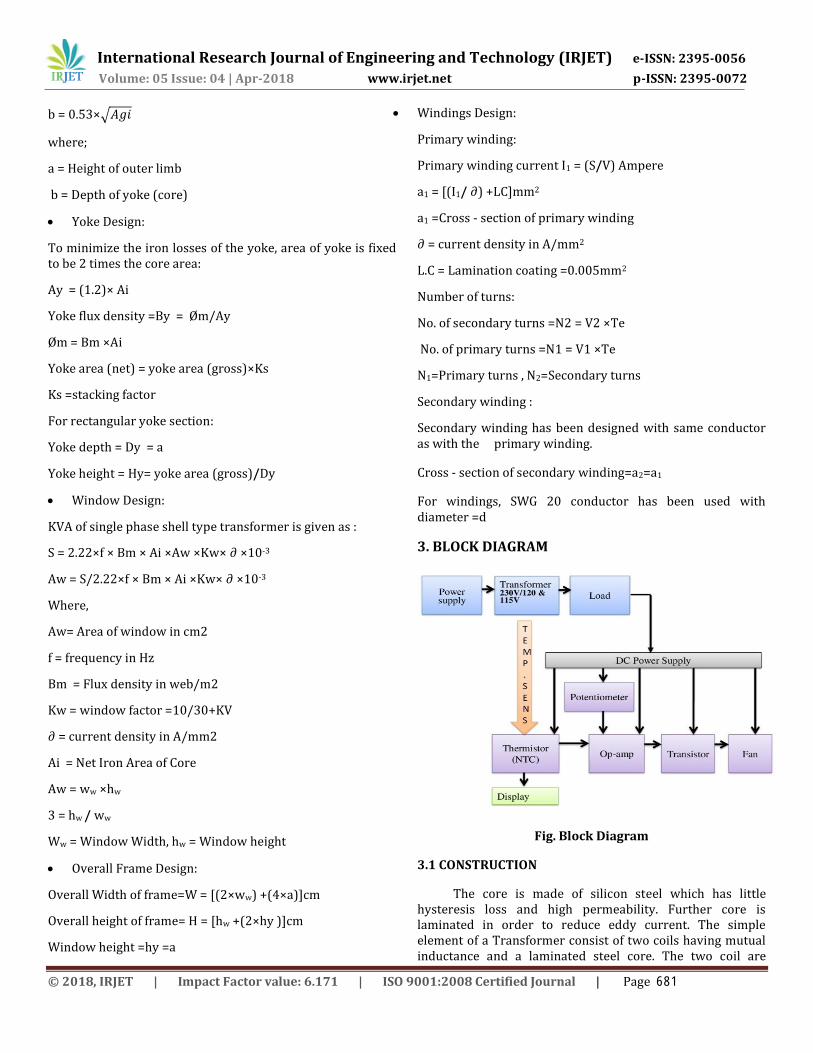
3. BLOCK DIAGRAM
Fig. Block Diagram
3.1 CONSTRUCTION
The core is made of silicon steel which has little hysteresis loss and high permeability. Further core is laminated in order to reduce eddy current. The simple element of a Transformer consist of two coils having mutual inductance and a laminated steel core. The two coil are
Volume: 05 Issue: 04 | Apr-2018 www.irjet.net p-ISSN: 2395-0072
© 2018, IRJET | Impact Factor value: 6.171 | ISO 9001:2008 Certified Journal | Page 681

International Research Journal of Engineering and Technology (IRJET) e-ISSN: 2395-0056
insulated from each other and the steel core. The primary and secondary winding is not physically connected, but magnetically linked to each other. The eddy current loss is minimized by laminating the core, the laminations being insulated from each other by dainty coat of core plate varnish or oxide layer on the surface. The silicon steel laminated to ‘E’ and ‘I’ stamping due to the more number. The single phase transformer have used in solo winding. Which are connected to AC source is known as primary winding and other winding is connected to load as soon as secondary winding. The primary winding is wound to centre limb to E stamping core and these winding laminated by insulating coil .and the insulating paper also wound to primary winding an the secondary winding is wound to over the primary winding. The primary winding and secondary winding is not electrically connected but are magnetically connected and the flux is produce by core of transformer.
4. METHODOLOGY
The transformer mechanism on principal is mutual induction. A transformer is a static device, which is transfer electric power from one circuit to another circuit without any variation in frequency. It can rise or lower the voltage in circuit but with a corresponding increase or decrease current. The circuit link by common magnetic flux in its simplest form, it consists of two inductive coils which are electrically separated but magnetically linked through a path of low reluctance. The ac supply is connected to the primary winding, an alternating flux is step up in laminated core, most of which is linked with the other oil in which it produces mutually induced EMF If the second coil circuit is close a current flow in intended so electric energy transfer from the first coil into second coil. The first coil connected to electrical supply is known as primary winding and load are connected to secondary winding. A transformers are often used to step down voltages in the 115-120 V range and voltages in the 230V range - for example, providing 115 V or 120 V (with taps) from 230 V input, allowing equipment designed for 115 or 120 V to be used with a 230 V supply
5. RESULT AND DISCUSSION:
This section describes the results of our testing and shows that tests are performed .This section discuss the result of losses of transformer and protected against the heating of transformer.
By implementing our project the following results were obtained:
For residential we are getting a supply of 230V and through step down transformer we are converting it into 115V and 120V.
6. CONCLUSION:
Transformer is the most significant component of power system. A good design for efficiency increase is a challenge in the fabrication of a transformer. Lesser efficient transformers are poorly designed because the losses occurring in a transformer are more likely considered the design flow. Transformers can be made maximum efficient if fabricated using the precise dimensions. The construction of this 1000Watts (1KVA), 220Volts transformer at a 50Hz frequency was a gradual process from gathering of materials to testing of components. In this project, we came to conclusion that the use of transformer for short circuit and open circuit test overall construction of transformer and winding regular. We learn process of troubleshooting of this transformer. We get information and knowledge about connections of this transformer. This project is a low cost, reliable, effective, protective and efficient. This project gives us to learn about good things and lot of knowledge of protection methods.
7. REFERENCES
1. Martin J. Heathcote. 1988. J and P Transformer book. Oxford university press.
2. Say M.G. 2005. Performance and Design of AC Machines, CBS publishers India..
3. P. Gill, “Electrical Power Equipment Maintenance and Testing”, 2nd edition., CRC Press, Taylor & Francis Group. 2009.
4. Stephen J. Chapman, “Electrical Machinary Fundamentals”, BAE SYSTEMS Austrailia.
5. Sawhney A.K. 2006. Electrical Machine Design, Dhanapat Rai publishers, India.
6. R.K. Agarwal, “Principles of Electrical Machine Design”, S. K. Kataria & Sons, 2009.
Volume: 05 Issue: 04 | Apr-2018 www.irjet.net p-ISSN: 2395-0072
© 2018, IRJET | Impact Factor value: 6.171 | ISO 9001:2008 Certified Journal | Page 682