design and fabrication of a hic compliant bulkhead
TRANSCRIPT

Design and Fabrication of a HIC Compliant Bulkhead
Hamid LankaraniNational Institute for Aviation Research
Wichita State UniversityEmail: [email protected]
Fire & Cabin Safety Research ConferenceAtlantic City, New Jersey
October 22-25, 2001

Fire & Cabin Safety Research Conference October 22 – 25, 2001
Problem Statement
The compliance with the Head Injury Criteria (HIC) poses a significant problem for aerospace industry
HIC =max
2.5
)(1
∫ dttat2
t 1)( 1t−t2 )( 1t−t2
Where, a(t) is the head resultant acceleration of the Part 572 Hybrid IIATD in g’s and t1 and t2 are the response times to maximize the function.
Non injurious if :Non injurious if : HICHIC < 1000< 1000
HIC problems encountered in:
Bulkhead Bulkhead Class DividersClass DividersCabin Furnishings Cockpit Glare Shields Cabin Side Walls Row-to-Row Instrument Panel Entry Door Steps Wind Screen Posts/Side Posts
Fire & Cabin Safety Research Conference October 22 – 25, 2001
Development Of HIC Compliant Bulkhead
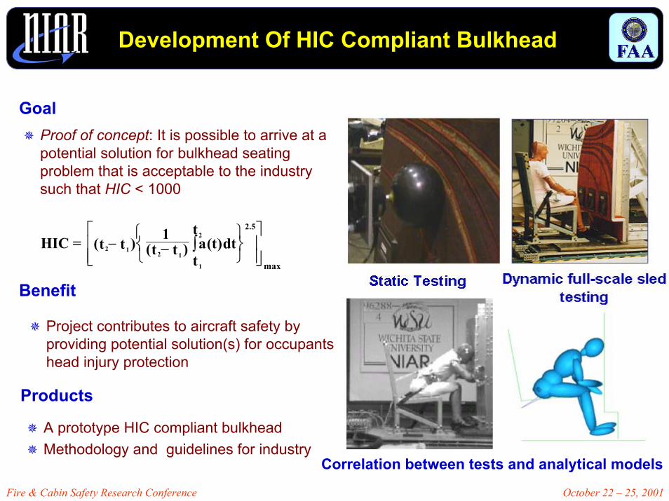
GoalProof of concept: It is possible to arrive at a potential solution for bulkhead seating problem that is acceptable to the industry such that HIC < 1000
HIC =max
2.5
)(1
∫ dttat2
t 1)( 1t−t2 )( 1t−t2
Benefit
Project contributes to aircraft safety by providing potential solution(s) for occupants head injury protection
Products
A prototype HIC compliant bulkheadMethodology and guidelines for industry
Correlation between tests and analytical models
Fire & Cabin Safety Research Conference October 22 – 25, 2001
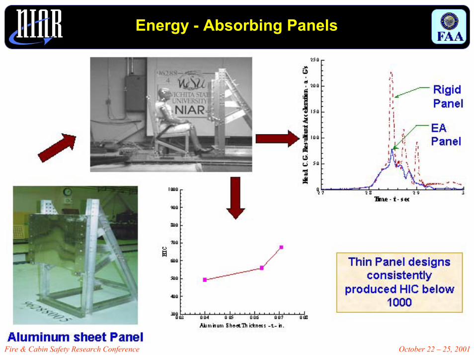
Energy - Absorbing Panels

Fire & Cabin Safety Research Conference October 22 – 25, 2001
Baseline Tests – Typical Production Bulkhead

Fire & Cabin Safety Research Conference October 22 – 25, 2001
Modification Of Production Bulkheads
Fire & Cabin Safety Research Conference October 22 – 25, 2001
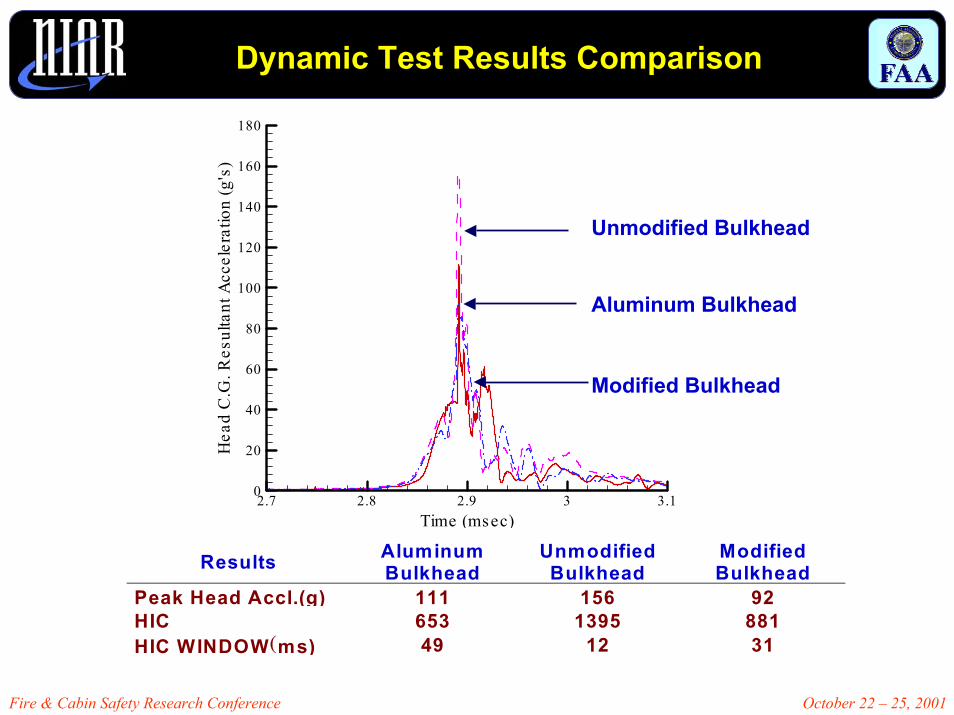
Dynamic Test Results Comparison
2.7 2.8 2.9 3 3.1Time (msec)
0
20
40
60
80
100
120
140
160
180
Hea
dC
.G.R
esul
tant
Acc
eler
atio
n(g
's)
Unmodified Bulkhead
Aluminum Bulkhead
Modified Bulkhead
Results Aluminum Bulkhead
Unmodified Bulkhead
Modified Bulkhead
Peak Head Accl.(g) 111 156 92 HIC 653 1395 881 HIC WINDOW (ms) 49 12 31

Fire & Cabin Safety Research Conference October 22 – 25, 2001
Validated Analytical Model
Biodynamic models were developed and validated against dynamic sled tests
Static tests were conducted to obtain load-deflection properties of the bulkhead

Fire & Cabin Safety Research Conference October 22 – 25, 2001
Sample Analytical and Dynamic Test Results Comparison

Fire & Cabin Safety Research Conference October 22 – 25, 2001
ATD Response for Different Seat Setbacks
Seat setback 33 in. Seat setback 35 in. Seat setback 38 in.
Dynamic Sled Tests on Aluminum PanelsDynamic Sled Tests on Aluminum Panels
56055280816067484838
6205811401414034474635
9188351661683232454633
AnalysisTestAnalysisTestAnalysisTestAnalysisTest
HICHead C.G Peak Accel.(g’s)
Head Impact Angle(deg)
Head Impact Velocity
(ft/s)
Seat setback
(In.)
Fire & Cabin Safety Research Conference October 22 – 25, 2001
Design Guidelines for HIC Attenuation
Stiffness - k1 - lb./in.0 100 200 300 400 500 600
0
200
400
600
800
1000
1200
1400
1600
HIC
Stiffness - k – lb/in0 100 200 300 400 500 600
0
200
400
600
800
1000
1200
1400
1600
HIC
300 400 500 600 700Crus h S tre ngth - Fcr - lbsCrush Strength - Fcr - lb
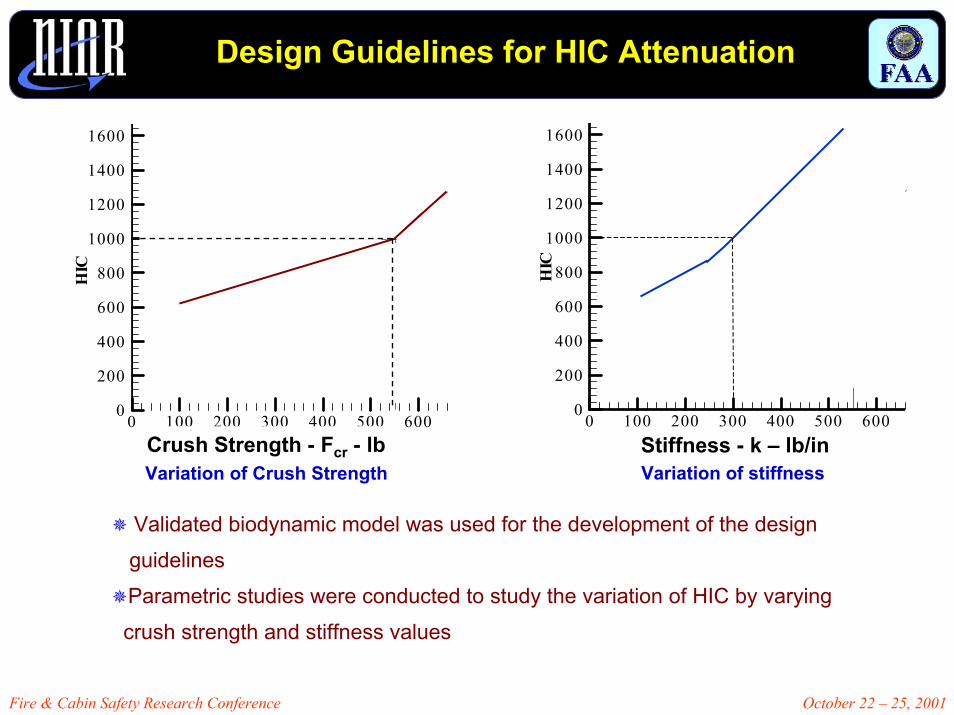
Variation of stiffnessVariation of Crush Strength
Validated biodynamic model was used for the development of the design guidelinesParametric studies were conducted to study the variation of HIC by varyingcrush strength and stiffness values

Fire & Cabin Safety Research Conference October 22 – 25, 2001
Fixture Design
Fabrication of test rig
The existing test rig was modified to replicate proper attachment points
Modifications were made to the rig to ensure that no additional support was provided to the bulkhead
attachment points
attachment points
Cross member
Modification of attachment points on the test rig

Fire & Cabin Safety Research Conference October 22 – 25, 2001
Bulkhead Materials
Bulkhead panel compositionHoneycomb core2-ply Epoxy fiberglass face sheetsCovered with carpet used typically in aircraft installations
Selected based on design guidelines and from sled tests conducted at NIAR and CAMI
Both metallic and non-metallic cores were studied for the design of the bulkhead
Metallic cores
Non-Metallic cores

Fire & Cabin Safety Research Conference October 22 – 25, 2001
Composition and Properties of Bulkhead Panels
Bulkhead Panel Composition
Fiberglass face sheets on either side
Aluminum honeycomb core
2.02.03.0psiDensity
240
3/80.040.74
1.000
TEKLAM
275
1/80.040.74
1.000
TEKLAM N510E
310psiFlat wise Compression
1/8inCore0.04inFacings0.74lb/sq ftWeight1.000inThickness
TEKLAM N510UnitProperty
First Series Second SeriesProperties of the acquired panels
Third Series
Carpet typically used in aircraft installations
Yes
Fiberglass
Aluminum Honeycomb
TEKLAM
Yes
2-ply Epoxy Fiberglass
Nomex Honeycomb
TEKLAM N510E
NoCarpet
2-ply Phenolic FiberglassFacings
Nomex HoneycombCore
TEKLAM N510Bulkhead Series
Second Series Third SeriesFirst Series
Lay-up of the bulkhead panel-TEKLAM III Series

Fire & Cabin Safety Research Conference October 22 – 25, 2001
Dynamic Tests with First Series of Bulkheads
3 3.1 3.2 3.3Time (Sec)
10
20
30
40
50
60
70
80
90
100
110
120
130
140
Res
ulta
ntH
ead
C.G
Acc
eler
atio
n
T1=
3.01
615
T2=
3.11
43
HIC = 1376
Dynamic sled tests were conducted at NIAR on the first series of bulkheads, the stiffest ones, to evaluate the performance of these bulkheads for accelerations in the head of 49 CFR Part 572, Subpart B of the ATD
Sled test # 01008-2
Resultant head acceleration
52.871145035
55.169155033
Avg. Accl. (g)∆t (ms)HICSeat Setback
Test Results
∴ First series of bulkheads failed

Fire & Cabin Safety Research Conference October 22 – 25, 2001
Dynamic Tests with Second Series of Bulkheads
3 3.023.043.063.08 3.1 3.123.143.163.18 3.2 3.223.243.263.28 3.3Time (S e c)
20
40
60
80
100
120
140
160
Res
ulta
ntH
ead
C.G
Acc
eler
atio
n
T1=
3.08
94
T2=
3.09
43
HIC = 781
Dynamic sled test was conducted on the second series of bulkheads to determine head accelerationsBulkheads less stiff than the first seriesbulkheads
Test Results
Resultant head acceleration
118.84.978135
82.421.4132133
Avg. Accl. (g)∆t (ms)HICSeat Setback
Sled test # 01008-4
∴ Second series of bulkheads failed

Fire & Cabin Safety Research Conference October 22 – 25, 2001
Dynamic Tests with Third Series of Bulkheads
Sled tests conducted at both smaller and larger seat setback distances
HIC values obtained below the threshold value of 1000 for both seat setback
Sled test # 01008-12
2.9 3 3.1Time -t- s ec
10
20
30
40
50
60
70
80
90
100
110
120
130
140
Hea
dC
.GR
esul
tant
Acc
eler
atio
n-g
's
He ad C.G res ultant acce leration Time his tory and HIC calculation
tc1
=2.
9166
t1=
2.92
99
t2=
3.00
25
tc2
=3.
0138
tc1 - contact s tart timetc2 - contact end timeHIC - 935
Resultant head acceleration
Test Results
62.82293533
35.323.316535
Avg. Accl. (g)∆t (ms)HICSeat Setback
∴ The proof of concept is demonstrated

Fire & Cabin Safety Research Conference October 22 – 25, 2001
Design Methodology
Fire & Cabin Safety Research Conference October 22 – 25, 2001
Hybrid Analytical Method to Estimate Stiffness
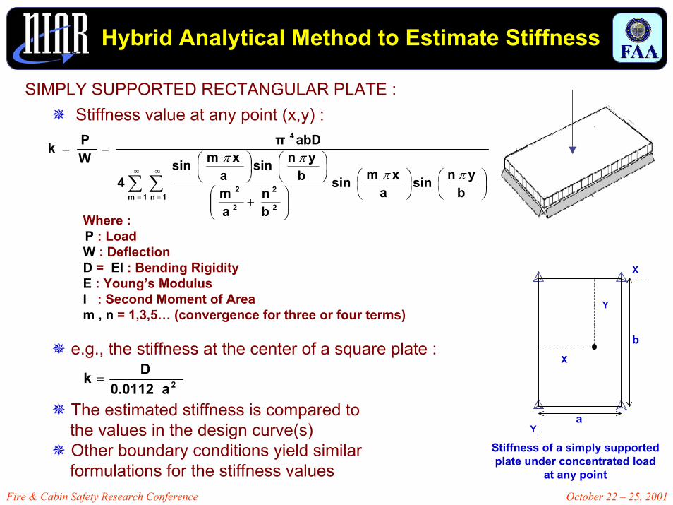
Stiffness value at any point (x,y) :
Where :P : Load W : Deflection D = EI : Bending RigidityE : Young’s Modulus I : Second Moment of Aream , n = 1,3,5… (convergence for three or four terms)
e.g., the stiffness at the center of a square plate :
The estimated stiffness is compared tothe values in the design curve(s)Other boundary conditions yield similar formulations for the stiffness values
Stiffness of a simply supported plate under concentrated load
at any point
X
b
a
Y
X
Y
∑ ∑∞
=
∞
=
+
==
1m 1n2
2
2
2
4
bynsin
axmsin
bn
am
bynsin
axmsin
4
abDπWPk
ππππ
a 0.0112Dk 2=
SIMPLY SUPPORTED RECTANGULAR PLATE :
Fire & Cabin Safety Research Conference October 22 – 25, 2001
Hybrid Analytical Method to Estimate Stiffness (cont’d)
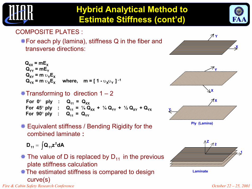
COMPOSITE PLATES :Y
XFor each ply (lamina), stiffness Q in the fiber and transverse directions:
QXX = mEXQYY = mEYQXY = m υYEXQYX = m υXEX where, m = [ 1 - υXυY ] –1
Transforming to direction 1 – 2For 0° ply : Q11 = QXXFor 45° ply : Q11 = ¼ QXX + ¼ QYY + ½ QXY + QYXFor 90° ply : Q11 = QYY
Equivalent stiffness / Bending Rigidity for the combined laminate :
The value of D is replaced by D11 in the previous plate stiffness calculationThe estimated stiffness is compared to design curve(s)
Y
X
Y
X
Ply (Lamina)
Z2
1
dAzQD 21111 ∫=
Laminate

Fire & Cabin Safety Research Conference October 22 – 25, 2001
Finite Element Analysis to Estimate Stiffness
Constraining points of the bulkhead
Finite element mesh of the bulkhead
Perform FEM analysis
Finite Element Analysis can be performed on a bulkhead design to estimate the stiffness at the vicinity of the head impact
The estimated stiffness is compared to the design curve(s)

Fire & Cabin Safety Research Conference October 22 – 25, 2001
Static Test to Evaluate Stiffness
0 1 2 3 4 5De fle ction (inche s )
0
100
200
300
400
500
600
700
800
Load
(lbs)
Load Vs De fle ction
Load Curve
Unload Curve
K
Static testing on bulkheads to obtain load-deflection characteristics
Sample load-deflection characteristics and bulkhead stiffness
For more complex compositions of the bulkhead materials and geometries, the bulkhead needs to be fabricated first
Static test is conducted on a fabricated bulkhead to evaluate the stiffness at the point of impact
The stiffness value is compared to the design curve(s)

Fire & Cabin Safety Research Conference October 22 – 25, 2001
Concluding Remarks
HIC compliant bulkheads were designed, fabricated and tested for aircraft interior installation.
A design methodology was developed for the development of HIC compliant bulkheads.
The methodology requires estimation of the stiffness of the designed bulkhead. The estimated stiffness will be compared to the ones from the design curve(s) for HIC attenuation.
Stiffness of the Teklam panels will be estimated/evaluated and plotted vs. the design curve(s)
Project highlight’s the FAA’s main objective of enhancing passenger safety.