design and fabrication of a 2-axis electrothermal mems ... · micromachines article design and...
TRANSCRIPT

micromachines
Article
Design and Fabrication of a 2-AxisElectrothermal MEMS Micro-Scanner for OpticalCoherence Tomography †
Quentin A. A. Tanguy 1,2,*, Sylwester Bargiel 1, Huikai Xie 2, Nicolas Passilly 1, Magali Barthès 1,Olivier Gaiffe 1, Jaroslaw Rutkowski 1, Philippe Lutz 1 and Christophe Gorecki 1
1 FEMTO-ST Institute, CNRS UMR6174, University of Bourgogne Franche-Comté, 25000 Besançon, France;[email protected] (S.B.); [email protected] (N.P.); [email protected] (M.B.);[email protected] (O.G.); [email protected] (J.R.); [email protected] (P.L.);[email protected] (C.G.)
2 Department of Electrical & Computer Engineering, University of Florida, Gainesville, FL 32611, USA;[email protected]
* Correspondence: [email protected]; Tel.: +33-769-388-345† This paper is an extended version of our paper published in 2016 IEEE International Conference on Optical
MEMS and Nanophotonics (OMN), Tanguy, Q.A.A., Duan, C., Wang, W., Xie, H., Bargiel, S., Struk, P., Lutz, P.& Gorecki, C., A 2-axis electrothermal MEMS micro-scanner with torsional beam.
Academic Editor: Kazunori HoshinoReceived: 31 March 2017; Accepted: 1 May 2017; Published: 5 May 2017
Abstract: This paper introduces an optical 2-axis Micro Electro-Mechanical System (MEMS)micromirror actuated by a pair of electrothermal actuators and a set of passive torsion bars.The actuated element is a dual-reflective circular mirror plate of 1 mm in diameter. This innermirror plate is connected to a rigid frame via a pair of torsion bars in two diametrically oppositeends located on the rotation axis. A pair of electrothermal bimorphs generates a force onto theperpendicular free ends of the mirror plate in the same angular direction. An array of electrothermalbimorph cantilevers deflects the rigid frame around a working angle of 45 for side-view scan.The performed scans reach large mechanical angles of 32 for the frame and 22 for the in-framemirror. We denote three resonant main modes, pure flexion of the frame at 205 Hz, a pure torsionof the mirror plate at 1.286 kHz and coupled mode of combined flexion and torsion at 1.588 kHz.The micro device was fabricated through successive stacks of materials onto a silicon-on-insulatorwafer and the patterned deposition on the back-side of the dual-reflective mirror is achieved througha dry film photoresist photolithography process.
Keywords: optical Micro Electro-Mechanical System (MEMS); Micro Optical Electro-MechanicalSystem (MOEMS); electrothermal actuation; torsion bar; dry photoresist; dual-reflective mirror;optical coherence tomography
1. Introduction
Optical Micro Electro-Mechanical System (MEMS) micro-scanners are exploited by a largevariety of applications that usually require large displacement range, high operating frequencies,miniaturization, simplicity of packaging and integration. Various methods, such as piezoelectric,electrostatic, electromagnetic and electrothermal technologies [1] have been used to develop devicesable to measure each application’s requirements. Among them, electrothermal actuation clearly standsout in terms of high performance, real time diagnosis, miniaturization of devices and endoscopy-basedimaging. Although its working frequency is usually lower than for other actuation techniques, it stilladequately reaches paces compatible with real time imaging [2]. MEMS electrothermal micro-scanners
Micromachines 2017, 8, 146; doi:10.3390/mi8050146 www.mdpi.com/journal/micromachines

Micromachines 2017, 8, 146 2 of 11
have a small size, high fill factor, high displacement range, low-voltage actuation and are relativelylinear which makes them particularly adapted for in vivo endoscopic Optical Coherence Tomography(OCT) imaging applications [3].
The micro-scanner proposed in this paper (shown in Figure 1a) was designed and fabricated inorder to be, in a future perspective, embedded into a Swept-Source OCT (SS-OCT) endomicroscopicprobe (Figure 1b) based on a Mirau micro-interferometer [4].
Figure 1. (a) Survey of the 2-axis Micro Electro-Mechanical System (MEMS) micro-scanning device.(b) Section plane of the different elements constituting the future endoscopic probe with the MEMSmicro-scanner on top of the Mirau micro-interferometer for Optical Coherence Tomography (OCT)imaging process along with dynamical feedback control of the mirror position.
Many MEMS micromirrors use a set of four electrothermal bimorph actuators located on the foursides of the central mirror plate [5–7]. During actuation or scanning, the center of these mirrors’ platehas to be partially maintained into a fixed position; first, by applying an offset voltage and second,by driving each pair of opposite actuators with a differential drive scheme [7]. However, the mirrorplate is still subject to fluctuation with surrounding temperature and to uncontrolled changes dueto vibrations or disturbances. In addition to these flaws, angular sensing mechanisms are usuallyunavailable, so that they are left uncontrolled [8] or with mere open-loop controls [9]. Concerning thefew systems that demonstrate a close loop control, a single surface is used for both target operation andposition sensing as in [10–12]. Conversely, for applications where one reflective side is to be exclusivelydedicated to the main task as for OCT, phosphorescence or two-photon microscopy, exploiting theother side of the mirror is a reliable trade-off for direct position sensing compared to intermediatesensing methods [13,14], easy to be carried out at a macro scale in a preliminary stage. Our MEMSdevice is a 2-axis electrothermal scanning system characterized by a large scanning range, a torsionbar (Figure 2), a novel actuation mechanism (Figures 3 and 4a) and a dual-reflective aluminum-coatedmirror plate (Figure 4a,c). The Mirau micro-interferometer associated with the swept source performsan axial scan (A-scan). Once the micro-scanning device is embedded on top of it, two additional B-scanaxes can be realized so that a 3D image can be obtained.
2. Design of the Device
This micromirror was designed to increase the stability of the in-frame mirror and to provide largescanning ranges over a large bandwidth at low driving voltage in order to allow in vivo operation andremedy to the lack of possibility of feedback control of the micromirrors. It shows off two reflectivesurfaces on both sides of the plate, appreciated for multi-use applications where the dynamics of

Micromachines 2017, 8, 146 3 of 11
the mirror plate need to be accurately controlled. Indeed, an optical position detector can sense thereal-time angle on one of the two reflective sides. For actuation, a pair of meshed electrothermalactuators is associated to a set of torsion bars that helps keeping the central axis of the mirror steady.These structures are represented in Figure 1 in green and blue colors, respectively. The mirror plateis consequently tilted inside the frame using the pair of Meshed Inverted-Series-Connected (MISC)electrothermal actuators located on both sides of the plate. The actuators are inverted one from anotherand apply a force in the opposite direction on the mirror plate generating the rotation around the axisof roll. Meanwhile, the pair of torsional bars, that are collinear to the virtual axis of roll, maintains theaxis of the mirror in the plane of the outer frame, thus bringing stability to the system over a widefrequency range. A Silicon On Insulator (SOI) substrate ensures mechanical and electrical bondingsupport to the outer frame which also bends out of plane. This rotative motion around an axis ofpitch is made possible by a bimorph cantilever array (sketched in red color in Figure 1). Although it isactuated, the frame acts as a support for the in-frame mirror plate. The main frame and mirror plateare made of a 30 µm-thick SOI device layer.
2.1. Torsion Bar
The torsion bars are used to prevent the mirror plate from oscillating around the roll axis,thus restricting the motion to a pure rotation. The materials used for the torsion beams are limited tothose used in the bimorph to simplify the fabrication process. They are made of a “sandwich” structure,composed of layers of SiO2/Pt/Al/SiO2 respectively. The torsion bars were purposely dimensionedso that the expression of the bending mode of the torsion rods is minimized and does not impactthe torsional motion. The stiffness of the bending mode is reported in [5,15,16] and is related to theresonance frequency through Equations (1)–(6):
kb =
√Ewt3
4L3 , (1)
where L, w, t refer respectively to the length, width, and thickness of the torsion bar and m to the massof the mirror plate. The frequency of the bending mode is given by:
fb =1
2π
√kbm
(2)
The torsion mode stiffness of the system can be estimated from:
kφ = 2kt + 2L2
m4
kb (3)
with kt =µwt3
3L.
(1 − 192
π5
(tw
) ∞
∑n=1,3,5,...
1n5 tanh(
nπt2w
)
)(4)
the free torsion stiffness as reported in [17,18]. Finally, the frequency of the torsion mode is given by [1]:
ft =1
2π
√kt
Jt, (5)
with kt =2µIt
L where It is the second moment of area of the torsion shaft, Jt the moment of inertia ofthe mirror plate, µ = E
2(1+ν)the shear modulus of elasticity, E the average Young’s modulus and ν
the Poisson’s ratio. The torsion frequency can also be calculated via the second moment of area fora rectangular-sectioned bar given by [18]:
It = wt3(
13− 0.21
tw(1 − t4
12w4 )
), (6)

Micromachines 2017, 8, 146 4 of 11
where w and t are respectively the width and thickness of the torsion bar.The bending mode frequency of the torsion bar is chosen to be twice as high as its torsion mode
frequency. To do so, the bar is 3.3 µm thick, 180 µm long and 28 µm wide. Figure 2 shows the torsionbar before and after release for different conditions and a schematic cross section of the torsion bar canbe found in Figure 5j. The Si layer from the device layer located underneath the torsion bar (Figure 2a)does not remain in the released structure. Otherwise, it would hold the whole structure and eventuallyculminate in the breaking of the MISC electrothermal actuators. The layer of Al is sandwiched betweenthe main layers of SiO2 and brings ductility to the torsion. The aluminum somewhat pushes away theyield stress breaking point of the structure making it more reliable regarding dynamical torsion andfatigue resistance. If not, the high residual stress initially induced in the actuators during fabricationwould lead to fatal damages as pointed out in Figure 2d.
(a) (b)
(c) (d)
Figure 2. SEM pictures of torsion bar: (a) Sandwich bar from the backside before complete release.A narrow bridge of Si still holds the structure. (b) Sandwich bar from the backside after release.(c) Sandwich bar from the front side after release. (d) Example of Al-free torsion bar after release,broken under excessive torsion stress.
2.2. Electrothermal Actuation & MISC Actuators
The actuators are often cumbersome and are responsible for a much larger footprint of the finaldevice than the size of the mirror plate. This issue has been tackled in some cases by modifying theshape of the actuators as in [19]. We present here an actuator based on Inverted-Series-Connected(ISC) electrothermal actuators as demonstrated in [7] but providing more flexibility and a higherdisplacement. It is a mesh of ISC actuators in series and in parallel that optimizes the space aroundthe mirror plate to increase the displacement and the force of the actuators without degrading the fillfactor. The principle of the meshed ISC (MISC) actuator is shown in Figure 3.

Micromachines 2017, 8, 146 5 of 11
(a) (b) (c)
(d) (e) (f)
Figure 3. Schematic build up of the Meshed Inverted Series Connected (MISC) actuator.(a) Fundamental bimorph cantilever beam (tip-tilt and lateral displacement). (b) ISC actuator (Lateralshift). (c) Double S-shaped configuration (piston motion). (d) Pair of double S-shaped actuators inparallel (Stiffness and stability increased). (e) Cumbersome double actuator (increased displacement).(f) MISC actuator.
The MISC actuator is the latest evolution of four generations of shapes of electrothermal actuators:the single bimorph cantilever is the core element shown in Figure 3a and reported in [20,21]. In [6,7],bimorphs were connected in series as in Figure 3b,c including inverted and non-inverted bimorphs(whose cross sections are shown respectively in Figure 5k,l) to get rid of the tip-tilt effect, bypassthe lateral shift and end up into a pure vertical translative motion called piston motion. These latterstructures were then interconnected in parallel as in Figure 3d to increase the overall motion stability.Figure 3e shows an intermediate structure and was reported by [22]. The MISC actuator shownin Figure 3f is the structure actuating the micromirror and can be seen, as fabricated in Figure 4b.The torsion bars generate a counter momentum in the opposite direction of the momentum createdby the two actuators. Hence, the actuators need to be able to provide a higher force and a largerdisplacement than that which can be provided by conventional ISC actuators. For a comparable spaceoccupied, the MISC actuators provide a higher force, a larger displacement and a higher flexibility.This latter advantage is also highly appreciated during the release process and brings more supplenessfor industrial fabrication where the dispersion of parameters on a single wafer can be significant.The bimorph is a sandwich of 1.1 µm of Al and 1 µm of SiO2. A thin heater layer of 1500 Å of Ptinsulated in a sheath of thin SiO2 is wrapped between the Al and the SiO2 as shown in Figure 5c.
2.3. Dual-Reflective Mirror Plate
The mirror is coated with aluminum on both sides of the plate using E-beam evaporation.The deposition on the upper side is 1.1 µm thick and is performed during the same Al metalization asfor the bimorphs. The Al layers of the front side mirror and of the electrothermal bimorph cantileversare realized in one step using the same photomask to simplify the complete fabrication process.Therefore, the Al of the mirror plate has the same thickness as the layer of the bimorphs. The backsideof the mirror is the side used to scan the focused laser beam and its smoothness is critical for the OCTimage quality. Hence, the deposition is done at very low deposition rate (1.2 Å s−1) while the substrateis being rotated at a speed of 10 rpm. SEM pictures of the reflective front and back side are shownrespectively in Figure 4a,c.
Micromachines 2017, 8, 146 6 of 11
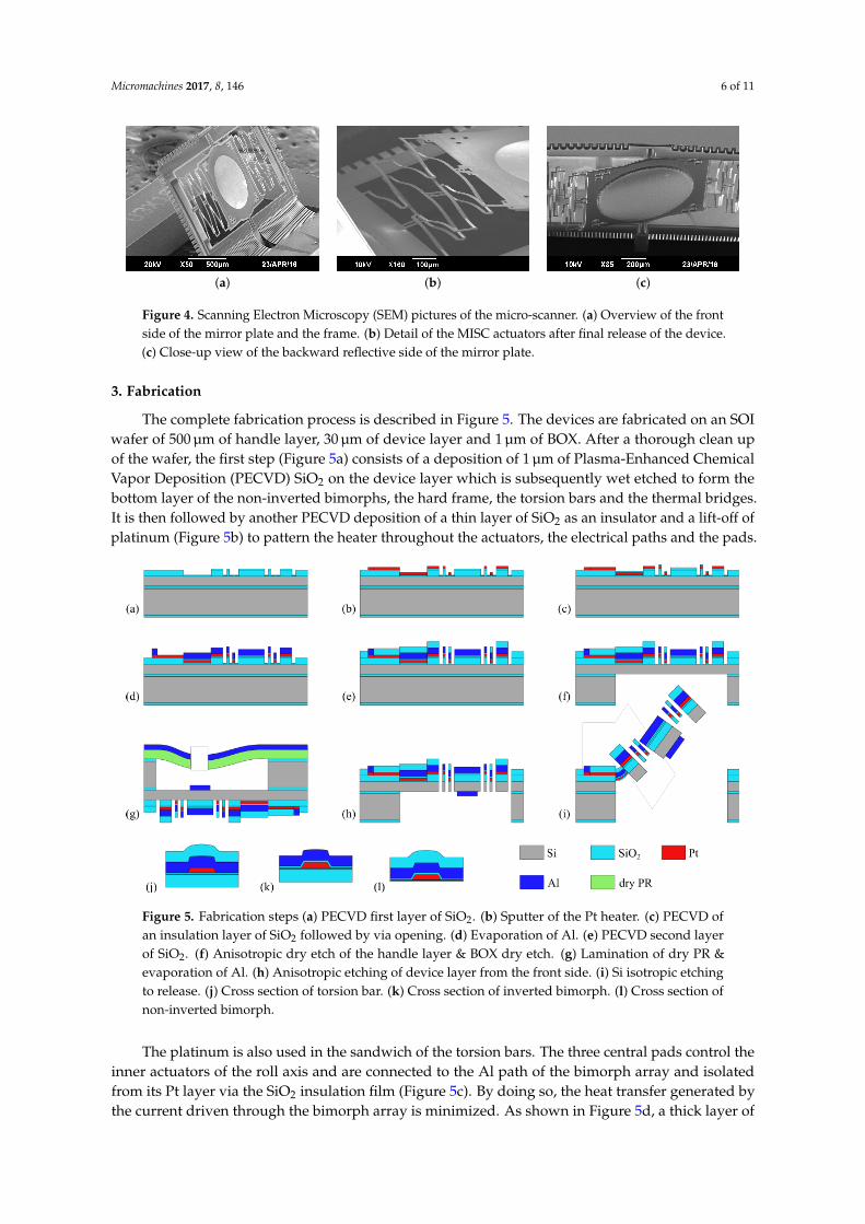
(a) (b) (c)
Figure 4. Scanning Electron Microscopy (SEM) pictures of the micro-scanner. (a) Overview of the frontside of the mirror plate and the frame. (b) Detail of the MISC actuators after final release of the device.(c) Close-up view of the backward reflective side of the mirror plate.
3. Fabrication
The complete fabrication process is described in Figure 5. The devices are fabricated on an SOIwafer of 500 µm of handle layer, 30 µm of device layer and 1 µm of BOX. After a thorough clean upof the wafer, the first step (Figure 5a) consists of a deposition of 1 µm of Plasma-Enhanced ChemicalVapor Deposition (PECVD) SiO2 on the device layer which is subsequently wet etched to form thebottom layer of the non-inverted bimorphs, the hard frame, the torsion bars and the thermal bridges.It is then followed by another PECVD deposition of a thin layer of SiO2 as an insulator and a lift-off ofplatinum (Figure 5b) to pattern the heater throughout the actuators, the electrical paths and the pads.
Figure 5. Fabrication steps (a) PECVD first layer of SiO2. (b) Sputter of the Pt heater. (c) PECVD ofan insulation layer of SiO2 followed by via opening. (d) Evaporation of Al. (e) PECVD second layerof SiO2. (f) Anisotropic dry etch of the handle layer & BOX dry etch. (g) Lamination of dry PR &evaporation of Al. (h) Anisotropic etching of device layer from the front side. (i) Si isotropic etchingto release. (j) Cross section of torsion bar. (k) Cross section of inverted bimorph. (l) Cross section ofnon-inverted bimorph.
The platinum is also used in the sandwich of the torsion bars. The three central pads control theinner actuators of the roll axis and are connected to the Al path of the bimorph array and isolatedfrom its Pt layer via the SiO2 insulation film (Figure 5c). By doing so, the heat transfer generated bythe current driven through the bimorph array is minimized. As shown in Figure 5d, a thick layer of

Micromachines 2017, 8, 146 7 of 11
1.1 µm of Al is deposited by evaporation (to facilitate the lift-off process) following a photolithographyof 3.5 µm of AZ nLOF2035 for the bimorphs, the mirror plate on the front side, the torsion bars,the electrical paths and the pads. We used pure Al, which was then protected by a thin coat of Cr of150 Å to prevent oxidation.
A second layer of 1 µm of SiO2 is deposited by PECVD and patterned through RIE/ICP dry etchto form the top layer of the inverted bimorphs. This step is represented in Figure 5e.
The handle layer is anisotropically etched through DRIE to form the device’s backside cavity(Figure 5f). The exposed BOX is also etched with RIE/ICP until the buried face of the device layer isreached. Then Al is deposited onto the mirror plate’s backside by evaporation. A dry film photoresistDuPont TM WBR2050 was laminated at 85 C on the backside of the SOI wafer held by a carrier waferbefore exposition.
The final release stage of the device divides into two substages respectively shown in Figure 5h,i.The first one consists of an anisotropic dry etch all the way through the device layer followed byan isotropic etch to release the actuators. The isotropic etch should not be performed longer thannecessary to avoid ablating SiO2 from the deformable elements which could eventually damage orbreak them. The isotropic process time is interrupted when the frame and the inner actuators pop outof the plane. At that step, a plasma O2 can be used to get rid of the impurities remaining on the chip.An SEM picture of the micro scanner after release can be found in Figure 4a.
Finally, several released chips are packaged onto a generic PCB support customized for handlingand characterization of the micro-devices (Figure 6a). The micro-scanners are bonded onto the centralAu pad with silver epoxy glue and electrically connected to the PCB pads by wire-bonding (Figure 6b).
(a) (b)
Figure 6. PCB support for the MEMS micro-scanner handling and testing. (a) Overview of the multi-usePCB with the micro device in the center, and connectors on both sides. (b) Zoomed-in picture of themicro device bonded onto the central gold pad with silver epoxy glue and wire bonding on Cu/Aupads for electrical routing.
4. Characterization
After release, the electrical resistances of the roll axis actuators in parallel and the pitch axisactuator are 1.07 kΩ and 1.34 kΩ, respectively. The optical setup is shown in Figure 7.
A laser beam is directed onto the MEMS micromirror which reflects it towards a diffusing screen.The latter is observed from its backside by an ultra fast Phantom TMMiro M120 camera. The framedeclines by 32 from an initial angle of 70 to a final angle of 38 reached at a voltage of 17 V (178 mW)while the mirror plate achieves a mechanical sweep range of 22 deflecting from an initial angle of18 to −4 for a voltage of 16.5 V (188 mW) (Figure 8a). The characteristics of power consumption andangular displacement as a function of the voltage applied are also shown in Figure 8.

Micromachines 2017, 8, 146 8 of 11
l
M1
M2
TL Camera
Screen
PSD
Micro-scanner
BE
LASER
BSd
D L
Figure 7. Optical setup implemented for the MEMS micro-scanner statical and dynamical characterization.BE: beam expander, M1, M2: mirrors, BS: beam splitter, PSD: Photo Sensing Detector, TL: tube lens.
0 2 4 6 8 10 12 14 16 18Voltage (V)
5
0
5
10
15
20
Mec
hani
cal a
ngle
of r
oll a
xis (
)
35
40
45
50
55
60
65
70
Mec
hani
cal a
ngle
of p
itch
axis
()
0 2 4 6 8 10 12Voltage (V)
0
20
40
60
80
100
120
Pow
er c
onsu
med
(mW
) pitch axisroll axis
(a) (b)
0 1 2 3 4 5 6 7Voltage applied on r-Axis (V)
0
2
4
6
8
10
12
14
Ang
ular
dis
plac
emen
t ( ) pitch axis
roll axis
0 2 4 6 8 10 12Voltage applied on p-Axis (V)
0
5
10
15
20
Ang
ular
dis
plac
emen
t ( ) pitch axis
roll axis
(c) (d)
Figure 8. (a) Statical angular displacement of the mirror on the roll axis (in green) and of the frame onthe pitch axis (in red). (b) Power consumption vs. voltage applied for both axes. (c) Statical relativeangular displacement of both axes when only the roll axis is driven. (d) Statical relative angulardisplacement of both axes when only the pitch axis is driven.
A Polytec TMMEMS Analyser was used to establish the frequency response of the micromirror.A white noise with an amplitude 1.5 V and an offset of 3 V was applied on the actuators one by one,and the magnitude of the deflection of the frame and the mirror plate was measured in dB. The Bodediagrams are shown in Figure 9. The coupling between the roll axis and the pitch axis is unilateral:when the inner actuator is driven, the heat is dissipated into the mirror plate, through the frame

Micromachines 2017, 8, 146 9 of 11
and through the bimorph array whose temperature increases at the same time, contributing into thecross-coupling of the two axes. In this situation, we observe four resonant modes: pure pitch motion at205 Hz, pure roll motion of the torsional mirror plate at 1.286 kHz, a mode with both components at1.588 kHz and a fourth mode that is less influential because of its high damping. Conversely, when thebimorph array is actuated, only the first pitch mode is observed at 205 Hz.
0 500 1000 1500 2000 2500 3000 3500 4000Frequency (Hz)
60
40
20
0
20
Mag
nitu
de (d
B)
outer actuation
inner actuation
Figure 9. Superimposed frequency responses of the system when the voltage is applied on the pitchaxis (outer actuator) in red and on the roll actuator (inner actuator) in green.
Finally, Lissajous laser scans have been recorded by the high-speed camera (at 30 kfps) when themicromirror is actuated at its resonance frequencies. Corresponding time elapsed scans are shown inFigure 10 (after 4 ms, 17 ms and 45 ms). In these conditions, if, on the one hand, a resolution of 10 µm issought at a working distance of 5 mm from the mirror as in [4], and on the other hand, a 90 kHz A-scanrate swept-source is employed (requiring to interpolate the 30 kHz experimental scans), it wouldthen require 45 ms, corresponding to an imaging frequency of 22 Hz, to cover 99 % of a scanned areaof 770 µm × 270 µm. At this frequency, and because of the Lissajous type of scanning, a significantnumber of pixels is averaged. Larger averaging, e.g., when 95 % of the scanned area is illuminatedmore than 9 times, can be reached at a frequency of 5 Hz.
4 2 0 2 42
1
0
1
2
Y sc
an a
ngle
()
(a) (b) (c)4 2 0 2 4
X scan angle ()4 2 0 2 4
Figure 10. Time elapsed Lissajous laser scanning patterns recorded by the high speed camera at 30 kfps,after (a) 4 ms. (b) 17 ms. (c) 45 ms.
Acknowledgments: This work was supported by the LabEx Action program (contract ANR-11-LABX-0001-01),by the French RENATECH network and its FEMTO-ST technological facility as well as the US National ScienceFoundation under award #1512531. I would also like to give thanks to Vincent Maurice and Jean-Marc Cote fortheir support.
Author Contributions: S.B., H.X., P.L. and C.G. supervised the work; Q.T. and S.B. designed the devices; Q.T.fabricated the devices; J.R., Q.T. and N.P. designed the instrumentation and the experimental setup; Q.T., N.P.,O.G. and M.B. modeled and characterized the devices; N.P. and O.G. carried out calculations and data treatmentfor the results interpretation; H.X. and S.B wrote a draft of the manuscript and Q.T., S.B., P.L., H.X., N.P., O.G., J.R.and M.B. contributed to the scientific interpretation of the resutls and the edition of the manuscript.

Micromachines 2017, 8, 146 10 of 11
Conflicts of Interest: The authors declare no conflict of interest.
Abbreviations
The following abbreviations are used in this manuscript:
MEMS Micro Electro-Mechanical SystemMOEMS Micro Optical Electro-Mechanical SystemSCS Single Crystal SiliconOCT Optical Coherence TomographySS Swept SourceISC Inverted Series ConnectedMISC Meshed ISCSOI Silicon On InsulatorBOX Buried OxideBOE Buffered Oxide EtchPECVD Plasma-Enhanced Chemical Vapor DepositionCTE Coefficient of Thermal ExpansionRIE Reactive-Ion EtchingICP Inductive Coupled PlasmaGRIN GRadient INdexPSD Position Sensing Detector
References
1. Petersen, K.E. Silicon torsional scanning mirror. IBM J. Res. Dev. 1980, 24, 631–637.2. Sun, J.; Xie, H. MEMS-based endoscopic optical coherence tomography. Int. J. Opt. 2011, 2011, 825629.3. Sun, J.; Guo, S.; Wu, L.; Liu, L.; Choe, S.W.; Sorg, B.S.; Xie, H. 3D In Vivo optical coherence tomography
based on a low-voltage, large-scan-range 2D MEMS mirror. Opt. Express 2010, 18, 12065–12075.4. Struk, P.; Bargiel, S.; Froehly, L.; Baranski, M.; Passilly, N.; Albero, J.; Gorecki, C. Swept source optical
coherence tomography endomicroscope based on vertically integrated mirau micro interferometer: Conceptand technology. IEEE Sens. J. 2015, 15, 7061–7070.
5. Wu, L.; Xie, H. A large vertical displacement electrothermal bimorph microactuator with very small lateralshift. Sens. Actuators A Phys. 2008, 145–146, 371–379.
6. Todd, S.T.; Jain, A.; Qu, H.; Xie, H. A multi-degree-of-freedom micromirror utilizing inverted-series-connected bimorph actuators. J. Opt. A Pure Appl. Opt. 2006, 8, S352.
7. Jia, K.; Pal, S.; Xie, H. An electrothermal tip-tilt-piston micromirror based on folded dual S-shaped bimorphs.J. Microelectromech. Syst. 2009, 18, 1004–1015.
8. Kobayashi, T.; Maeda, R. Piezoelectric optical micro scanner with built-in torsion sensors. Jpn. J. Appl. Phys.Part 1 Regul. Pap. Short Notes Rev. Pap. 2007, 46, 2781–2784.
9. Wang, W.; Chen, J.; Zivkovic, A.S.; Tanguy, Q.A.; Xie, H. A compact Fourier transform spectrometer ona silicon optical bench with an electrothermal MEMS mirror. J. Microelectromech. Syst. 2016, 25, 347–355.
10. Han, F.; Wang, W.; Zhang, X.; Xie, H. Modeling and control of a large-stroke electrothermal MEMS mirrorfor fourier transform microspectrometers. J. Microelectromech. Syst. 2016, 25, 750–760.
11. Wang, W.; Chen, J.; Zivkovic, A.S.; Xie, H. A Fourier Transform Spectrometer based on an electrothermalMEMS mirror with improved linear scan range. Sensors 2016, 16, 1611.
12. Zhao, Y.; Tay, F.E.H.; Zhou, G.; Chau, F.S. Fast and precise positioning of electrostatically actuated dual-axismicromirror by multi-loop digital control. Sens. Actuators A Phys. 2006, 132, 421–428.
13. Fujita, T.; Maenaka, K.; Takayama, Y. Dual-axis MEMS mirror for large deflection-angle using SU-8 softtorsion beam. Sens. Actuators A Phys. 2005, 121, 16–21.
14. Tseng, V.F.G.; Xie, H. Simultaneous piston position and tilt angle sensing for large vertical displacementmicromirrors by frequency detection inductive sensing. Appl. Phys. Lett. 2015, 107, 214102.
15. Lowet, G.; Audekercke, R.V.; der Perre, G.V.; Geusens, P.; Dequeker, J.; Lammens, J. The relation betweenresonant frequencies and torsional stiffness of long bones in vitro. Validation of a simple beam model.J. Biomech. 1993, 26, 689–696.

Micromachines 2017, 8, 146 11 of 11
16. Timoshenko, S. Analysis of Bi-metal thermostats. J. Opt. Soc. Am. 1925, 11, 233–255.17. Ji, C.H.; Kim, Y.K. Electromagnetic micromirror array with single-crystal silicon mirror plate and aluminum
spring. J. Lightw. Technol. 2003, 21, 584–590.18. Young, W.; Roark, R.; Budynas, R. Roark’s Formulas for Stress and Strain. McGraw-Hill: New York, NY, USA,
2002; Volume 7.19. Liu, L.; Pal, S.; Xie, H. MEMS mirrors based on a curved concentric electrothermal actuator. Sens. Actuators
A Phys. 2012, 188, 349–358.20. Todd, S.T.; Xie, H. Steady-state 1D electrothermal modeling of an electrothermal transducer.
J. Micromech. Microeng. 2006, 16, 665–665.21. Jain, A.; Kopa, A.; Pan, Y.; Feeder, G.K.; Xie, H. A two-axis electrothermal micromirror for endoscopic optical
coherence tomography. IEEE J. Sel. Top. Quantum Electron. 2004, 10, 636–642.22. Samuelson, S.R.; Xie, H. A large piston displacement MEMS mirror with electrothermal ladder actuator
arrays for ultra-low tilt applications. J. Microelectromech. Syst. 2014, 23, 39–49.
c© 2017 by the authors. Licensee MDPI, Basel, Switzerland. This article is an open accessarticle distributed under the terms and conditions of the Creative Commons Attribution(CC BY) license (http://creativecommons.org/licenses/by/4.0/).