design and experimental analysis of rectangular wavy micro channel heat sink
TRANSCRIPT

International Journal of Innovative Research in Advanced Engineering (IJIRAE) ISSN: 2349-2763 Issue 11, Volume 3 (November 2016) www.ijirae.com
_________________________________________________________________________________________________ IJIRAE: Impact Factor Value – SJIF: Innospace, Morocco (2015): 3.361 | PIF: 2.469 | Jour Info: 4.085 |
Index Copernicus 2014 = 6.57 © 2014- 16, IJIRAE- All Rights Reserved Page -54
Design and Experimental Analysis of Rectangular Wavy
Micro Channel Heat sink Manjeet Singh Rakesh Kumar M. Tech Thermal Engineering Mechanical Engineering Department I.K.Gujral Punjab Technical University I.K.Gujral Punjab Technical University Abstract — An experimental investigation has been explore in order to study the flow of fluid and heat transfer characteristics on a Rectangular Wavy microchannel heat sink. Various applications are envisaged for the use of microchannel heat sink in electrical and electronic power generation and distribution. The Heat sink with microchannel is designed on an Aluminium specimen with Rectangular Wavy configuration with a channel cross section of 1mm x 0.5mm.To improve the heat transfer performance of the cooling system is achieved by using nanoparticles in the fluid passing through the microchannel heat sink. Results are presented by using different concentration (with 1% to 3%) of Nano fluids in water for the heat sink. Various cooling characteristics including thermal resistance, temperature drop and pressure drop across the microchannel heat sink are analysed for different volume concentrations, different volumetric flow rates and Reynolds number. Other significant characteristics for the measurement of heat transfer characteristics across this microchannel heat sink are also analysed and presented in this experiment.
Keywords — Rectangular Wavy micro channel; Heat transfer characteristics; Reynolds number, Nusselt number, Thermal resistance
I. INTRODUCTION
With the development of new electronic and computing technology and rapid increase in power density and miniaturization of electronic packages, traditional cooling using fans or metal fins may be unable to meet the ever-increasing cooling demands of emerging electronic devices. [1] y. Sui et.al has studied the laminar liquid / water flow and heat transfer in three-dimensional wavy microchannels with rectangular cross section by numerical simulation. Alok kumar bahera et.al in [2] study a three-dimensional numerical analysis to understand the effect of axial wall conduction on conjugate heat transfer during single phase pulsatile flow in a square microchannel with wavy walls. With the miniaturization of modern micro electronics systems, the need for increased flux removal from a unit surface area has increased. So that its requires to higher cooling rates and heat removal capacities of the natural convection from any electronic chip. This has led to the growing demands of mini/micro channel systems. Including the wavy walls of micro channels, turbulent flow is induced by mixing that leads to higher heat transfer rate as compared to laminar flow. Direct liquid cooling using micro channels could be performed in order to reduce the heat produced in electronic devices. Hassan et.al [3] and m.k. Kang et.al [4] analysis that various methods of single phase and two phase (boiling) cooling are available other than direct cooling techniques as it provides potentially higher heat removal capacities. But latter leads to the problems of condensation, saturation temperature, critical heat flux, etc. S.g. Kandlikar et.al in [5] provides an overall view of micro channels development in the thermal and fabrication aspects of microchannels as applied in the microelectronics and other high heat-flux cooling applications. Microchannels may be defined as flow passages through hydraulic diameters in the range of 10 to 200 micrometers. After study the advancement in heat transfer technology from a historical perspective, application of using microchannels in high heat flux cooling applications is discussed, and research done on various aspects of microchannel heat exchanger performance is reviewed. Single phase performance for liquids is expected to be still describable by the conventional equations; however the gas flow may be influenced by the rarefaction effects. Conventional microchannel heat sinks employ straight channels where streamlines of the coolant are nearly straight. This show poor mixing and inefficient heat transfer due to the induced laminar flow. Due to higher wall thickness of straight microchannels as compared to channel cross section, heat transfer characteristics significantly deteriorate in the flow directions of straight microchannels.

International Journal of Innovative Research in Advanced Engineering (IJIRAE) ISSN: 2349-2763 Issue 11, Volume 3 (November 2016) www.ijirae.com
_________________________________________________________________________________________________ IJIRAE: Impact Factor Value – SJIF: Innospace, Morocco (2015): 3.361 | PIF: 2.469 | Jour Info: 4.085 |
Index Copernicus 2014 = 6.57 © 2014- 16, IJIRAE- All Rights Reserved Page -55
This also leads to temperature variations across the channel length. Also, due to non uniform distribution of heat fluxes across the channel in most cases, it is difficult to remove the heat from some hot regions using the conventional microchannel heat sinks. This leads to the increasing needs in the development of conventional microchannel heat sinks considering various parameters like low cost, high heat flux removal, increased pressure drop across the microchannel, etc. These could be achieved by inducing a turbulent flow in the microchannel and increased mixing characteristics. Microchannels with wavy walls provide such higher heat flux removal by increased mixing and generating turbulence in the flow due to the stretching and folding of the flow element. This mechanism has been employed in many researches [6-9]. S. S. Y. Leung et.al in [10] presented 3d numerical simulations on the convective heat transfer in droplet flows in the microchannels with rectangular cross sections. The wavy microchannels were be able to significantly increase the heat transfer performance as compared to the straight channels with same cross section with very less change in pressure drop at the same time [11-15].due to various advantages and application of wavy microchannels over straight microchannels, these are suitable for incorporating with new computing and electronic cooling systems for high power applications. This could be achieved by replacing conventional straight microchannels with the wavy microchannel heat sinks as depicted in Fig. 1.
Fig. 1: Planar illustration of wavy microchannels with (a) constant wavelength; (b) decreasing wavelength (thus increasing relative waviness); (c) shorter wavelength (thus larger relative waviness) in certain regions along the flow direction [1].
II. EXPERIMENTAL SETUP
The experimental setup was designed for the analysis of microchannel heat sink with Rectangular Wavy configuration that included different sensors for temperature, pressure and flow rate measurement. Also, the designed setup included a data acquisition device build using microcontroller unit and interfaced to an output display unit. An inlet pump was used for letting in the fluid including water or Nano fluids at different concentrations. Various T-junctions were placed as mechanical joints between the paths are made of plastic connectors. A pipe is connected to the output of the T-junction. The pipe used for circulating the water and Nano fluid was made of plastic material.
Fig. 2: Complete Experimental Setup.
International Journal of Innovative Research in Advanced Engineering (IJIRAE) ISSN: 2349-2763 Issue 11, Volume 3 (November 2016) www.ijirae.com
_________________________________________________________________________________________________ IJIRAE: Impact Factor Value – SJIF: Innospace, Morocco (2015): 3.361 | PIF: 2.469 | Jour Info: 4.085 |
Index Copernicus 2014 = 6.57 © 2014- 16, IJIRAE- All Rights Reserved Page -56
A flow sensor (F1) is placed at inlet. The output of the flow sensor (F2) is given to the data acquisition device (DAQ) for monitoring purpose. Following the flow sensor (F1) and pressure gauge (P1) is connected at the input path and a temperature sensor (T1) placed for measuring the temperature of inlet flow stream. After this, different O-rings are used to reduce the dimension of pipe connected and a small diameter plastic pipe matching the inlet heat sink pipe is joined to the output of O-ring. This is then joined to the input of the micro channel heat sink. Another temperature sensor (T2) is placed onto the top of heat sink using thermal paste. Output of T2 is given to DAQ device. The output of the micro channel heat sink is joined with an output pipe of smaller diameter that is further connected to an O-ring to increase the pipe diameter. A larger diameter output pipe is connected to the O-ring connector output. This pipe is similar to the inlet pipe. Temperature sensor (T3) is placed in the outlet flow stream to measure the output water stream temperature. A pressure gauge (P2) is connected to the output of the pipe to measure the pressure of the output flow stream. Finally, the flow sensor (F2) is placed in the output flow stream to measure its flow rate. The output of T3 and F2 is also connected to the DAQ device.
III. PERFORMANCE EQUATION
= ………………… (1)
………………. (2)
………………….. (3)
….......................... (4)
IV. RESULT
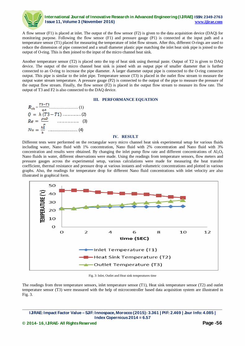
Different tests were performed on the rectangular wavy micro channel heat sink experimental setup for various fluids including water, Nano fluid with 1% concentration, Nano fluid with 2% concentration and Nano fluid with 3% concentration and results were obtained. By changing the inlet pump flow rate and different concentrations of Al2O3 Nano fluids in water, different observations were made. Using the readings from temperature sensors, flow meters and pressure gauges across the experimental setup, various calculations were made for measuring the heat transfer coefficient, thermal resistance and pressure drop at various instants and volumetric concentrations and plotted in various graphs. Also, the readings for temperature drop for different Nano fluid concentrations with inlet velocity are also illustrated in graphical form.
Fig. 3: Inlet, Outlet and Heat sink temperatures time
The readings from three temperature sensors, inlet temperature sensor (T1), Heat sink temperature sensor (T2) and outlet temperature sensor (T3) were measured with the help of microcontroller based data acquisition system are illustrated in Fig. 3.

International Journal of Innovative Research in Advanced Engineering (IJIRAE) ISSN: 2349-2763 Issue 11, Volume 3 (November 2016) www.ijirae.com
_________________________________________________________________________________________________ IJIRAE: Impact Factor Value – SJIF: Innospace, Morocco (2015): 3.361 | PIF: 2.469 | Jour Info: 4.085 |
Index Copernicus 2014 = 6.57 © 2014- 16, IJIRAE- All Rights Reserved Page -57
Fig. 4: Thermal resistance vs volumetric flow rate
It is depicted by the Fig. 4. The heat transfer measurements were performed on the Al Micro channel heat sink with rectangular wavy configuration for different volumetric flow rates. Input heat flux and volumetric flow rates were adjusted such that the difference in inlet and outlet temperatures was greater than 6°C in all the cases. From the energy balance equation, the steady state heat gain of the fluid flowing through MCHS is expressed as,
Here, the volumetric flow rate was measured with the help of flow meters at the inlet and the outlet interfaced with the Arduinouno board as data acquisition device. The average inlet temperature (T1) was obtained by taking the average of readings obtained from the inlet temperature sensor and the minimum outlet temperature (T2) was obtained by taking the minimum value of outlet temperature sensor readings. The overall average heat transfer coefficient for microchannel heat sink was obtained using,
Where is the total area available for convection on the MCHS. The mean total temperature was taken to be,
T3 is taken to be the outlet temperature on the experimental setup.
Fig. 5: Thermal Resistance vs Volumetric flow rate for various nanofluid concentrations with water Fig. 5 depicts the values of thermal resistance for water and nanofluids with different volumetric flow rate. It has been seen that as flow rate increases, thermal resistance for various fluids decreases. Water shows the highest thermal resistance, however Nano fluid mixture in water shows lower resistances. As the concentration of Nano fluid increases, thermal resistance decreases.

International Journal of Innovative Research in Advanced Engineering (IJIRAE) ISSN: 2349-2763 Issue 11, Volume 3 (November 2016) www.ijirae.com
_________________________________________________________________________________________________ IJIRAE: Impact Factor Value – SJIF: Innospace, Morocco (2015): 3.361 | PIF: 2.469 | Jour Info: 4.085 |
Index Copernicus 2014 = 6.57 © 2014- 16, IJIRAE- All Rights Reserved Page -58
It is minimum for 3% nanofluid concentration in water and maximum plain water without any nanofluids. Volumetric flow rate is varied by varying the knob at the inlet of the flow meter through which the fluid is passing. Thermal resistance is calculated in K/W by the designed data acquisition system by calculating the temperature from various temperature sensors, i.e. Junction temperature and inlet temperature. The variation of thermal resistance with different volume concentrations (ᴪ), is depicted in Fig. 6.
Fig. 6: Thermal Resistance vs Volume concentration for various nanofluid concentrations at Reynolds number = 99
Fig. 7: Thermal Resistance vs Volume concentration for various nanofluid concentrations at Reynolds number = 230
Fig. 7 depicts the values of thermal resistance at various volume concentrations for different nanofluid concentrations at a constant Reynold’s number = 230. It is seen that the values of thermal resistance decreases with increase in the values of ᴪ. Also, it is also depicted from Fig. 6 and Fig. 7 that, for the same values of volume concentrations, the value of thermal resistance reduces significantly with increasing the Reynold’s number from 99 to 230.
Fig. 8 illustrates the values of thermal resistance for different Reynolds number. It shows the highest values for water and decreases with increase in nanofluid concentration. Next, the readings for pressure drop were noted for water as well as different nanofluid concentrations and plotted with respect to Reynold's number. The graph is depicted by Fig. 9. From Fig. 9, it is depicted that pressure drop is highest for Nano fluid with 2% concentration and decreases as concentration of Nano fluid in water decreases and is the minimum for plain water for same Reynolds number. Also, the pressure drop increases with increase in Reynolds’s number.

International Journal of Innovative Research in Advanced Engineering (IJIRAE) ISSN: 2349-2763 Issue 11, Volume 3 (November 2016) www.ijirae.com
_________________________________________________________________________________________________ IJIRAE: Impact Factor Value – SJIF: Innospace, Morocco (2015): 3.361 | PIF: 2.469 | Jour Info: 4.085 |
Index Copernicus 2014 = 6.57 © 2014- 16, IJIRAE- All Rights Reserved Page -59
Fig. 8: Thermal Resistance vs Reynolds number for water and nanofluids with different concentrations
Fig. 9: Pressure drop vs Reynolds’s number rate for water and Nano fluids with different concentrations
Fig. 10: Temperature Inlet velocity for different nanofluid concentrations through square MCHS
International Journal of Innovative Research in Advanced Engineering (IJIRAE) ISSN: 2349-2763 Issue 11, Volume 3 (November 2016) www.ijirae.com
_________________________________________________________________________________________________ IJIRAE: Impact Factor Value – SJIF: Innospace, Morocco (2015): 3.361 | PIF: 2.469 | Jour Info: 4.085 |
Index Copernicus 2014 = 6.57 © 2014- 16, IJIRAE- All Rights Reserved Page -60
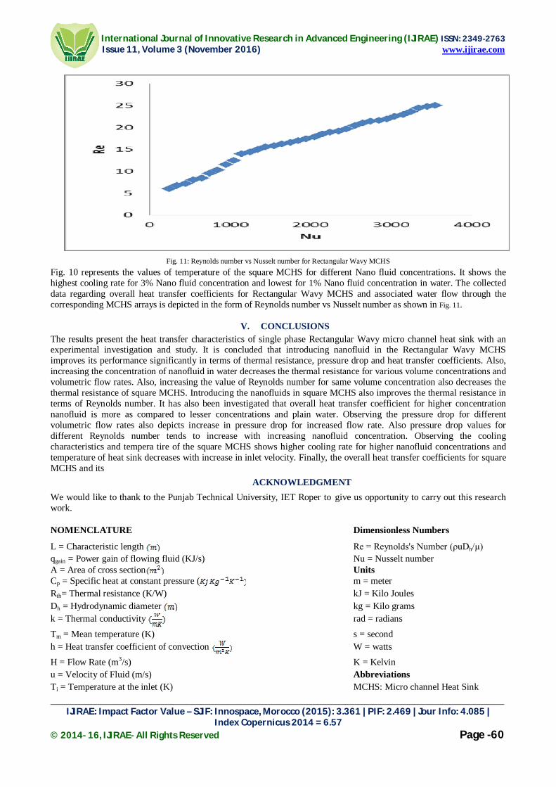
Fig. 11: Reynolds number vs Nusselt number for Rectangular Wavy MCHS Fig. 10 represents the values of temperature of the square MCHS for different Nano fluid concentrations. It shows the highest cooling rate for 3% Nano fluid concentration and lowest for 1% Nano fluid concentration in water. The collected data regarding overall heat transfer coefficients for Rectangular Wavy MCHS and associated water flow through the corresponding MCHS arrays is depicted in the form of Reynolds number vs Nusselt number as shown in Fig. 11.
V. CONCLUSIONS
The results present the heat transfer characteristics of single phase Rectangular Wavy micro channel heat sink with an experimental investigation and study. It is concluded that introducing nanofluid in the Rectangular Wavy MCHS improves its performance significantly in terms of thermal resistance, pressure drop and heat transfer coefficients. Also, increasing the concentration of nanofluid in water decreases the thermal resistance for various volume concentrations and volumetric flow rates. Also, increasing the value of Reynolds number for same volume concentration also decreases the thermal resistance of square MCHS. Introducing the nanofluids in square MCHS also improves the thermal resistance in terms of Reynolds number. It has also been investigated that overall heat transfer coefficient for higher concentration nanofluid is more as compared to lesser concentrations and plain water. Observing the pressure drop for different volumetric flow rates also depicts increase in pressure drop for increased flow rate. Also pressure drop values for different Reynolds number tends to increase with increasing nanofluid concentration. Observing the cooling characteristics and tempera tire of the square MCHS shows higher cooling rate for higher nanofluid concentrations and temperature of heat sink decreases with increase in inlet velocity. Finally, the overall heat transfer coefficients for square MCHS and its
ACKNOWLEDGMENT
We would like to thank to the Punjab Technical University, IET Roper to give us opportunity to carry out this research work.
NOMENCLATURE Dimensionless Numbers
L = Characteristic length Re = Reynolds's Number (ρuDh/µ) qgain = Power gain of flowing fluid (KJ/s) Nu = Nusselt number A = Area of cross section Units Cp = Specific heat at constant pressure ( m = meter Rth= Thermal resistance (K/W) kJ = Kilo Joules Dh = Hydrodynamic diameter kg = Kilo grams k = Thermal conductivity rad = radians
Tm = Mean temperature (K) s = second h = Heat transfer coefficient of convection W = watts
H = Flow Rate (m3/s) K = Kelvin u = Velocity of Fluid (m/s) Abbreviations Ti = Temperature at the inlet (K) MCHS: Micro channel Heat Sink

International Journal of Innovative Research in Advanced Engineering (IJIRAE) ISSN: 2349-2763 Issue 11, Volume 3 (November 2016) www.ijirae.com
_________________________________________________________________________________________________ IJIRAE: Impact Factor Value – SJIF: Innospace, Morocco (2015): 3.361 | PIF: 2.469 | Jour Info: 4.085 |
Index Copernicus 2014 = 6.57 © 2014- 16, IJIRAE- All Rights Reserved Page -61
To = Temperature at the outlet (K) DAQ: Data acquisition device Q = Heat Flux(W/m2) Greek Symbols α = Thermal diffusivity (m2/s) µ = Viscosity of the fluid (Ns/m2) ψ = Volume concentration (%) ρ = Density of Fluid (Kg/m3)
REFERENCES [1] Y. Sui, C.J. Teo *, P.S. Lee, Y.T. Chew, C. Shu, “Fluid Flow and heat transfer in wavy microchannels”,International
Journal of Heat and Mass Transfer 53 (2010) 2760–2772. [2]AlokNarayanBahera, Manoj Kumar Moharana, “Heat transfer in pulsatile flow through square microchannels with
wavy walls”, 23rd National Heat and Mass Transfer Conference and 1st International ISHMT-ASTFE Heat and Mass Transfer Conference IHMTC2015, 17-20 December, 2015, Thiruvananthapuram, India
[3] I. Hassan, P. Phutthavong, M. Abdelgawad, “Microchannel heat sinks: an overview of the state-of-the-art”, Micro scale Therm. Eng. 8 (2004) 183–205.
[4] M.K. Kang, J.H. Shin, H.H. Lee, K. Chun, “Analysis of laminar convective heattransfer in micro heat exchanger for stacked multi-chip module”, Microsyst.Technol. 11 (2005) 1176–1186.
[5] S.G. Kandlikar, W.J. Grande, “Evaluation of single phase flow in microchannels for high heat flux chip cooling – thermohydraulic performance enhancement and fabrication technology” , Heat Transfer Eng. 25 (8) (2004) 5–16.
[6] C.E. Kalb, J.D. Seader, “Heat and mass transfer phenomena for viscous flow incurved circular tubes” , Int. J. Heat Mass Transfer 15 (4) (1972) 801–817.
[7] J.H. Masliyah, K. NandaKumar, “Fully developed viscous flow and heat transfer in curved semi-circular sectors” ,AIChE J. 25 (3) (1979) 478–487.
[8] L. Wang, T. Yang, “Bifurcation and stability of forced convection in curved ductsof square cross-section”, Int. J. Heat Mass Transfer 47 (2004) 2971–2987.
[9] G. Yang, Z.F. Dong, M.A. Ebadian, “Laminar forced convection in a helicoidal pipe with fine pitch” , Int. J. Heat Mass Transfer 38 (5) (1995) 853–862.
[10] Zhizhao Chea, TeckNeng Wong, Nam-TrungNguyen, Chun Yang, “Three dimensional features of convective heat transfer in droplet-based microchannel heat sinks", International Journal of Heat and Mass Transfer”, November 2, 2015.
[11]M. Ghobadi1, Y. S. Muzychka2, “Heat transfer in spiral channel heat sink”, Proceedings of the ASME 2011 9th International Conference on Nanochannels, Microchannels, and MinichannelsICNMM2011, June 19-22, 2011 Edmonton, Alberta, CANADA
[12]Alok Narayan Bahera, Manoj Kumar Moharana,”Heat transfer in pulsatile flow through square microchannels with wavy walls”,23rd National Heat and Mass Transfer Conference and 1st International ISHMT-ASTFE Heat and Mass Transfer ConferenceIHMTC2015, 17-20 December, 2015, Thiruvananthapuram, India
[13] Mark E. Steinke1 and Satish G. Kandlikar2, “Single-phase heat transfer enhancement techniques in microchanneland minichannel flows Microchannels and Minichannels”- 2004, June 17-19, 2004, Rochester, New York, USA
[14]Dr. B. S. Gawali, V. B. Swami, S. D. Thakre,”Theoretical and experimental investigation of heat transfer characteristics through rectangular micro channel heat si”, International Journal of Innovative Research in Science, Engineering and Technology, Vol. 3, Issue 8, August 2014
[15] Z.Che, T. N. Wong, N.-T. Nguyen, “Heat transfer enhancement by recirculating flow within liquid plugs in microchannels”,International Journal of Heat and Mass Transfer 55 (2012) 1947–1956.