design and evaluation of power management support for upnp
TRANSCRIPT

Design and Evaluation of Power Management Support for UPnP Devices
A Master’s Thesis
by Jakob Klamra and Martin Olsson
Department of Communication Systems
Lund Institute of Technology
June 10, 2005
Supervisors: Christian Nyberg, Department of Communication Systems, Lund Institute of Technology Ken Christensen, Department of Computer Science and Engineering, University of South Florida

2
Abstract Universal Plug and Play (UPnP) is an emerging standard for automatic configuration of
network connected devices. All UPnP devices connected to the network must be fully powered up at all times to answer incoming requests and to maintain correct information about the state of the network. Using UPnP therefore means increased power consumption. In this thesis a design, implementation and evaluation of two different solutions to enable power management in UPnP are completed. Two power management proxies that allow devices to enter power sleep mode by taking over for some of the low level tasks of the sleeping devices are developed. Sleeping devices are woken up by a proxy when their device functionality is needed in the network. Using these new proxies, users of UPnP can reduce power consumption and increase the lifetime of battery driven UPnP devices. The proxies are tested in an UPnP network with several devices, showing that they solve the power management problem in UPnP. Estimations show that enabling power management in UPnP will save up to $320 million by 2008 in the US. It is expected that this thesis will contribute to the current work being done by the UPnP Forum to introduce power management to the UPnP standard.

3
Acknowledgments First of all we would like to thank our supervisor Ken Christensen for his professional
and personal commitment to our project that has gone far beyond what is expected of a faculty member. Without him this work would not have been possible.
We would like to thank our supervisor in Sweden, Christian Nyberg, for his help with this thesis.
We would like to thank the board members from USF: Miguel Labrador and Dewey Rundus for revising our thesis and giving us valuable comments.
We would like to thank Bruce Nordman from Lawrence Berkeley National Laboratory for coming up with the original idea of powersaving in UPnP that lead to this thesis and his help with the power savings estimations.
We would like to thank our fellow student Chamara Gunaratne for his valuable comments and support throughout the project.
We would like to thank Anna Whitlocks Minnesfond, Carl Erik Levins Stiftelse, Stiftelsen Carl Swartz Minnesfond and Stiftelsen Sigfrid och Walborg Nordkvist for their financial support.
Finally we would like to thank our girlfriends Nathalie and Julia and our families and friends for their support throughout this whole project and our stay in Florida.

4
Contents ABSTRACT .................................................................................................................................................. 2 ACKNOWLEDGMENTS............................................................................................................................ 3 ABBREVIATIONS ...................................................................................................................................... 6 NOTATION .................................................................................................................................................. 7 1 INTRODUCTION............................................................................................................................... 8
1.1 OVERVIEW OF UPNP .................................................................................................................... 8 1.1.1 A short introduction to UPnP ................................................................................................. 8 1.1.2 The history and future of UPnP............................................................................................ 12
1.2 OVERVIEW OF DEVICE CONTROL PROTOCOLS............................................................................. 12 1.2.1 SSDP..................................................................................................................................... 13 1.2.2 Jini ........................................................................................................................................ 14 1.2.3 Salutation.............................................................................................................................. 15
1.3 POWER MANAGEMENT AND UPNP............................................................................................. 16 1.3.1 Problem ................................................................................................................................ 16 1.3.2 Contribution ......................................................................................................................... 17
1.4 OUTLINE OF THE THESIS ............................................................................................................. 17 2 ENGINEERING ANALYSIS........................................................................................................... 19
2.1 REQUIREMENTS.......................................................................................................................... 19 2.2 ASSUMPTIONS ............................................................................................................................ 20 2.3 PARAMETERS FOR THE SOLUTION............................................................................................... 20 2.4 INTRODUCTION TO POWER MANAGEMENT PROXY ...................................................................... 21 2.5 CENTRALIZED PROXY, NO CHANGE TO DEVICES......................................................................... 21
2.5.1 Invisible proxy ...................................................................................................................... 22 2.6 CENTRALIZED PROXY, MINOR CHANGE TO DEVICES................................................................... 22
2.6.1 Cooperating proxy................................................................................................................ 22 2.6.2 Change in discovery answer................................................................................................. 22
2.7 NO PROXY, MAJOR CHANGE TO DEVICES .................................................................................... 23 2.7.1 Beacons................................................................................................................................. 23 2.7.2 Partial Wake-up.................................................................................................................... 23 2.7.3 New protocol for Power Management.................................................................................. 23 2.7.4 Less notifications and better wake-up .................................................................................. 24
3 DESIGN OF SOLUTIONS .............................................................................................................. 25 3.1 SELECTION OF SOLUTION............................................................................................................ 25
3.1.1 Grading of solutions ............................................................................................................. 25 3.1.2 Discussion of cooperating and invisible proxy ..................................................................... 28
3.2 DESIGN OF THE INVISIBLE PROXY............................................................................................... 29 3.3 DESIGN OF THE COOPERATING PROXY ........................................................................................ 33
4 IMPLEMENTATION OF SOLUTIONS........................................................................................ 38 4.1 IMPLEMENTATION TOOLS ........................................................................................................... 38 4.2 PROOF OF CONCEPT .................................................................................................................... 38
4.2.1 Wake-up of devices ............................................................................................................... 38 4.2.2 Sending of advertisement spoofed from other device............................................................ 39 4.2.3 Receiving and answering discovery intended for other device............................................. 39 4.2.4 Implementation of a UPnP power management service....................................................... 39
4.3 IMPLEMENTATION OF THE INVISIBLE PROXY .............................................................................. 39 4.3.1 Simplifications of the implementation of the invisible proxy ................................................ 41
4.4 IMPLEMENTATION OF COOPERATING PROXY .............................................................................. 42 4.4.1 Simplifications of the implementation of the cooperating proxy .......................................... 43

5
5 VALIDATION .................................................................................................................................. 44 5.1 DESCRIPTION OF TEST BED ........................................................................................................ 44
5.1.1 Software................................................................................................................................ 44 5.1.2 Computers............................................................................................................................. 45 5.1.3 Network................................................................................................................................. 45
5.2 VALIDATION OF THE INVISIBLE PROXY....................................................................................... 45 5.2.1 Test cases.............................................................................................................................. 46 5.2.2 Execution of test cases .......................................................................................................... 48
5.3 VALIDATION OF THE COOPERATING PROXY................................................................................ 50 5.3.1 Test cases.............................................................................................................................. 50 5.3.2 Execution of test cases .......................................................................................................... 52
6 ESTIMATED ENERGY SAVINGS................................................................................................ 54 6.1.1 Energy saving ....................................................................................................................... 54
7 CONCLUSIONS AND FUTURE WORK ...................................................................................... 58 7.1 CONCLUSIONS ............................................................................................................................ 58
7.1.1 Enabling new devices to use UPnP ...................................................................................... 58 7.2 SHORTCOMINGS OF THE TWO SOLUTIONS ................................................................................... 59 7.3 FUTURE WORK ........................................................................................................................... 60
7.3.1 Future for our solution ......................................................................................................... 61 A SSDP................................................................................................................................................... 63 B UPnP XML SCHEMES.................................................................................................................... 67 C GENA................................................................................................................................................. 72 D SOAP.................................................................................................................................................. 75 BIBLIOGRAPHY ...................................................................................................................................... 79

6
Abbreviations ARP – Address Resolution Protocol
DHCP – Dynamic Host Configuration Protocol
GENA – General Event Notification Architecture
HTTP – Hyper Text Transfer Protocol
IETF – Internet Engineering Task Force
IP – Internet Protocol
LPTF – Low Power Task Force
NIC – Network Interface Controller
RPC – Remote Procedure Call
RST – Reset Timer
SSDP – Simple Service Discovery Protocol
SOAP – Simple Object Access Protocol
TCP – Transport Control Protocol
TFP – Timer Forward Packet
TNE – Timer Notification Expired
TPD – Timer Process Discovery
TSE – Timer Subscription Expired
TSI – Timer Service Inactivity
TSN – Timer Send Notification
TSS – Timer Service Startup
TWA – Timer Wait for Alive
UDP – Universal Datagram Protocol
UPnP – Universal Plug and Play
URI – Uniformed Resource Identifier
URN – Uniform Resource Name
USN – Unique Service Name
UUID – Universally Unique Identifier
XML – Extensible Markup Language
VoIP – Voice over IP
WiFi – Wireless Fidelity
WOL – Wake On LAN

7
Notation Program code and message headers are formatted with Courier: SSDP:alive.
As a tool for the detailed design Finite State Machines (FSM) are used. These schemes show the different states of the design and the transitions to move between these states. In the description of FSMs the name of the states are formatted with capital letters: STATE. In the FSMs P stands for proxy, S for service and CP for control point. The text above the transitions in the FSMs shows which event that causes the transition and the text below the transitions shows which action the program takes.
All states are numbered from 1 and up and all transitions are numbered depending on which states the transition is between. For example a state in the control point FSM can be CP1, and the transition that goes from CP1 to CP2 is called CP12.
In the description of our test cases every step is either a test instruction or a verification point. Instructions are marked with ■ and verification points are marked with .
In the appendices that describe packets and XML schemes, standard courier font is used for static information (i.e. Location) and italic courier is used to describe non static information (i.e. path to the device).
Event
Action
STATE
Event
Action

8
1 Introduction
As the cost of advanced electronic devices for consumer use continues to decrease, the number of network enabled devices in a household is increasing. The increased number of devices also increases the consumption of electricity, whether the devices are connected to a power line or run on batteries. Lawrence Berkeley National Laboratory estimates that home IT equipment, such as office equipment and closely related communications devices, were responsible for consuming 280 kWh/year per American household in 2004 [33]. The prognosis for 2005 is even higher. Reducing this consumption will bring significant economic savings and environmental benefits. It will also extend the lifetime of battery driven devices. To achieve this we need power management aware protocols and devices.
In many protocols today network connected devices must always be fully powered up. This is needed to maintain correct information about the state of the network and to make sure that all messages on the network are received and answered properly. One of the protocols that require this is Universal Plug and Play (UPnP) [5]. UPnP requires devices to be fully powered on to perform periodic and trivial tasks.
One way to enable power management in UPnP and other similar protocols is to introduce a power management proxy that will take over a device’s duties in the network. This allows a device to enter power sleep mode. The proxy will wake up the device when there is a request for functionality from the device that the proxy cannot provide. Using this technique, allowing devices to enter power sleep mode, will save energy and increase battery life time.
1.1 Overview of UPnP Imagine that you just have bought a new printer that you would like to connect to your
home network so you can use the printer from all computers in your network. Normally you would have to go through the complicated procedure of setting up the shared printer manually. With UPnP you simply connect the printer to the network and all configurations can be done without having to press a single button. For example when you connect your laptop to the network it would automatically find the printer and be able to use it [1]. UPnP offers comprehensive peer-to-peer connectivity with a wide range of devices that makes scenarios like this possible.
1.1.1 A short introduction to UPnP UPnP is a protocol designed for automatic configuration of networks. The concept is an
extension of Microsoft’s Device Plug and Play [15], which automatically installs new hardware once it is connected to the computer. UPnP will automatically install devices once they are connected to the same network. UPnP is completely platform and media independent which means that your coffee pot could be able to communicate with your computer using a power line.
Every physical entity (such as computers, printers and mobile phones) is a device in an UPnP network. Further, every device can in turn contain embedded devices with its own
9
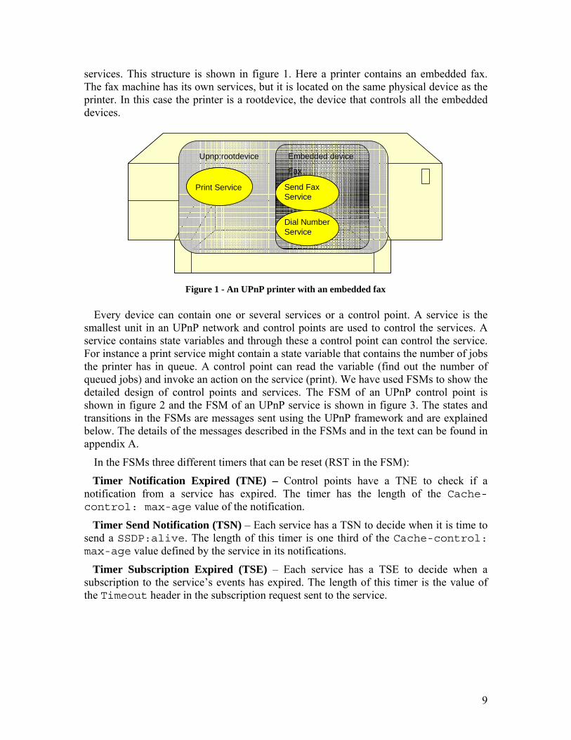
services. This structure is shown in figure 1. Here a printer contains an embedded fax. The fax machine has its own services, but it is located on the same physical device as the printer. In this case the printer is a rootdevice, the device that controls all the embedded devices.
Every device can contain one or several services or a control point. A service is the smallest unit in an UPnP network and control points are used to control the services. A service contains state variables and through these a control point can control the service. For instance a print service might contain a state variable that contains the number of jobs the printer has in queue. A control point can read the variable (find out the number of queued jobs) and invoke an action on the service (print). We have used FSMs to show the detailed design of control points and services. The FSM of an UPnP control point is shown in figure 2 and the FSM of an UPnP service is shown in figure 3. The states and transitions in the FSMs are messages sent using the UPnP framework and are explained below. The details of the messages described in the FSMs and in the text can be found in appendix A.
In the FSMs three different timers that can be reset (RST in the FSM):
Timer Notification Expired (TNE) – Control points have a TNE to check if a notification from a service has expired. The timer has the length of the Cache-control: max-age value of the notification.
Timer Send Notification (TSN) – Each service has a TSN to decide when it is time to send a SSDP:alive. The length of this timer is one third of the Cache-control: max-age value defined by the service in its notifications.
Timer Subscription Expired (TSE) – Each service has a TSE to decide when a subscription to the service’s events has expired. The length of this timer is the value of the Timeout header in the subscription request sent to the service.
Upnp:rootdevice
Print Service
Embedded device
Fax
Send Fax Service
Dial Number Service
Upnp:rootdevice
Print ServicePrint Service
Embedded device
Fax
Send Fax ServiceSend Fax Service
Dial Number ServiceDial Number Service
Figure 1 - An UPnP printer with an embedded fax

10
When a device joins a network it first obtains an IP address. This can be done either with automatic configuration through DHCP [32] or letting the device choose its own IP address using Auto IP [11]. Once an IP address has been obtained the next step is discovery. Discovery is how the different devices, services and control points are informed about each others presence. This is handled through the Simple Service Discovery Protocol (SSDP) (see appendix A). Any control point that connects to the network will scan for available devices (figure 2, transition CP01). Every new device on the network will announce its presence to all devices already connected (figure 3, transition S01). Every notification from a service has a limited lifetime. This means that the service has to reannounce its presence periodically (figure 3, state S11c and figure 2 transition CP11a). If a notification expires the service will be removed from the control point’s cache (figure 2, transition CP11a). When a service wants to leave the network it will send out a notification about the service becoming unavailable (figure 3, transition S13) and it will be removed from the control point’s cache (figure 2, transition C11a).
Figure 2 - FSM for UPnP control point
* SSDP message can be alive, byebye, or a discovery answer. ** Can be both new subscription and subcription renewal
LISTENING CP1
CP01 Connect
SSDP:discover multicast
USE SERVICE CP3
CP11a SSDP from S/TNE timeout*
Update cache, RST TNE
CP12 Request from application
HTTP GET to S
CP21 XML scheme from S
Present S
GET DESCRIPTION CP2
CP13 Request from application
SOAPAction to S
CP31 Action response from SWAIT FOR HTTP OK CP4
CP14a Application request /subscription timeout
SUBSCRIPTION to S**
CP14b Application request
UNSUBSCRIBE to S
CP41 HTTP OK from S / 30 sec timeout
CP11b NOTIFY from S
Update informationHTTP OK to S, RST TNE
LISTENING CP1
CP01 Connect
SSDP:discover multicast
USE SERVICE CP3USE SERVICE CP3
CP11a SSDP from S/TNE timeout*
Update cache, RST TNE
CP12 Request from application
HTTP GET to S
CP21 XML scheme from S
Present S
GET DESCRIPTION CP2
CP13 Request from application
SOAPAction to S
CP31 Action response from SWAIT FOR HTTP OK CP4
CP14a Application request /subscription timeout
SUBSCRIPTION to S**
CP14b Application request
UNSUBSCRIBE to S
CP41 HTTP OK from S / 30 sec timeout
CP11b NOTIFY from S
Update informationHTTP OK to S, RST TNE

11
After a control point has discovered all available services it will retrieve the exact details of the service that is expressed in an XML schema (figure 2, state CP2). With this information the service can be controlled using Simple Object Access Protocol (SOAP) (see appendix D) (figure 2, state CP3). Once a control point is ready to use a service it can show the user a graphical user interface by accessing the service’s control URL. This is a site formatted with standard HTML that is implemented in the service. Using a web browser the user can now control the service.
In an UPnP network a control point can subscribe to changes in a state variable in a service (figure 2, transition CP14a). If a control point subscribes to a variable change and the variable changes the service will send an event (figure 3, transition S14) to the control point (figure 2, transition CP11b) telling it what has changed. The event messages are expressed in XML and formatted using General Event Notification Architecture (GENA) (see appendix C).
All of the protocols mentioned above are presented in figure 4 that shows the whole UPnP stack as it is implemented in each device.
Figure 3 - FSM for UPnP service
*Can be new subscription, subscription renewal or unsubscription
LISTENING S1
S01 Connect
SSDP:alive multicast, RST TSNS12 SOAPAction from CP
S21 Action done
Action response to CP
SERVICE INVOKES ACTION S2
S11b SSDP:discover from CP
Discovery ans to CP
LEAVE NETWORK S3
S13 Disconnect
SSDP:bye bye multicast
WAIT FOR RESPONSE S4
S14 Change of state
NOTIFY to all subscribers
S41 HTTP OK from CP/ 30 sec timeout
S11e TSE timeout
Update subscription list
S11a HTTP GET from CP
XML scheme to CP
S11c TSN timeout
SSDP:alive multicastRST TSN
S11d UN/SUBSCRIBE from CP*
Update subscription listHTTP OK to CP, RST TSE
LISTENING S1
S01 Connect
SSDP:alive multicast, RST TSNS12 SOAPAction from CP
S21 Action done
Action response to CP
SERVICE INVOKES ACTION S2
SERVICE INVOKES ACTION S2
S11b SSDP:discover from CP
Discovery ans to CP
LEAVE NETWORK S3
S13 Disconnect
SSDP:bye bye multicast
LEAVE NETWORK S3
S13 Disconnect
SSDP:bye bye multicast
WAIT FOR RESPONSE S4
S14 Change of state
NOTIFY to all subscribers
S41 HTTP OK from CP/ 30 sec timeout
WAIT FOR RESPONSE S4WAIT FOR RESPONSE S4
S14 Change of state
NOTIFY to all subscribers
S41 HTTP OK from CP/ 30 sec timeout
S11e TSE timeout
Update subscription list
S11a HTTP GET from CP
XML scheme to CP
S11c TSN timeout
SSDP:alive multicastRST TSN
S11d UN/SUBSCRIBE from CP*
Update subscription listHTTP OK to CP, RST TSE

12
1.1.2 The history and future of UPnP UPnP devices and service descriptions are defined by the UPnP forum [5]. This forum
is an association of more than 700 vendors and was formed on October 18, 1999. The goal of the forum is to make networking simple and affordable, making it possible for everyone, independent of their computer knowledge, to have and maintain any type of physical network. An UPnP network is, from the consumer’s point of view, the ultimate network. It requires no configuration and it is easy to make different devices interact with each other.
One of the original ideas with UPnP was to allow mobile devices to connect to an existing network and use all available services without having to configure the device first. There are several large mobile companies, e.g. Nokia and Ericsson that participate in the UPnP forum working for mobile connectivity using UPnP. Today, UPnP is mostly used for media sharing and automatic configuration of gateways. There are several products available on the market that are UPnP certified. The target for these products is mostly end consumers with home networks. UPnP enables configuration-free home networks and offers user friendly solutions [6]. UPnP is implemented in the Windows XP operating system [1] which means that many PCs have UPnP abilities. The number of devices on the market that use UPnP is steadily increasing as the UPnP forum continues to release new device standards.
1.2 Overview of device control protocols SSDP is the discovery protocol used by UPnP. There are other discovery protocols
Figure 4 - UPnP Architecture
UPnP Vendor Specific
UPnP Forum Specific
UPnP Device Architecture
HTTP Multicast
SSDP GENA
HTTP Unicast
SSDP
HTTP
GENA
SOAP
GENA
UDP TCP
IP
UPnP Vendor Specific
UPnP Forum Specific
UPnP Device Architecture
HTTP Multicast
SSDP GENA
HTTP Unicast
SSDP
HTTP
GENA
SOAP
GENA
UDP TCP
IP

13
used by e.g. Jini [12], Salutation [13] and Bluetooth [14]. In this chapter the design of SSDP, Jini and Salutation are reviewed in order to investigate the resemblances and differences between UPnP and other device control protocols.
1.2.1 SSDP SSDP is based on the HTTP protocol to make resources available and discoverable on
the network. SSDP uses a decentralized communication model. This means that there is no central point in the network that keeps track of services and control points. Instead UPnP has a true peer-to-peer functionality where each device is aware of all other devices in the network.
Control points and services work together to discover each other and make their presence known on the network. When a service connects to the UPnP network it will make its presence known by multicasting a SSDP:alive message. This message contains information about the service and its location. Every control point that is interested in the offered service will add the announcement to its cache. This cache is used to keep track of all services that the control point can control. Every SSDP:alive message is only valid for a certain time that is defined in the message. Once this time has passed the information about the service will automatically be removed from the control point’s cache and the service will be considered disconnected from the network. To prevent this, the service has to readvertise its presence by sending out a new SSDP:alive and thus updating the cache of the control point.
When a control point connects to a SSDP network it needs to discover all services presently connected to the network that it can control. Therefore it initiates a search by multicasting SSDP:discover messages. In this message it is specified which type of service the discovery concerns and where the searching control point is located. Any service that matches the criteria in the SSDP:discover will answer the control point directly by sending a unicast message containing all the necessary information about the service. This allows the control point to add the service to its cache. As with SSDP:alive messages these announcements eventually time out and have to be updated with SSDP:alive to stay in the control point’s cache.
Control Pont
Service
Service
Service
discovery
answer
discovery
answer
discoveryanswer
Control PontControl Pont
ServiceService
ServiceService
ServiceService
discovery
answer
discovery
answer
discoveryanswer
Figure 5 - Discovery communication model of SSDP

14
When a service wants to leave an UPnP network it will multicast a SSDP:byebye message. This will allow the control points to immediately remove the service from its cache. Should a service leave the network abruptly without issuing SSDP:byebye the information in the control point’s cache will eventually time out. However, before this happen the control point still might try to invoke action on the service. The action will generate an error that allows the control point to update its cache. This situation should naturally be avoided, but it is a tradeoff. If the time out of a SSDP:alive is short an error situation is less likely to occur, but the SDDP:alive message has to be resent often, causing more network traffic. If the time out is too long on the other hand, the error situation is more likely to occur because the information in the control point’s cache will not be accurate until the advertisement times out.
The communication model of SSDP discovery is shown in figure 5. The details of SSDP, message structure and addressing are described in Appendix A.
1.2.2 Jini Jini is device control protocol for easy connection of devices in a home network and is
based on the Java programming language. All devices that run Jini must run on a Java platform. Just as the programming language, this system was constructed and is administrated by Sun [7][8][9][12]. The aim of Jini is similar to the one of UPnP, but the technologies differ. Jini consists of three main protocols: discovery, join and lookup. Jini differs from UPnP because it does not have a decentralized approach to communication. Instead Jini uses a central server that contains information about all services.
When a new service connects to the Jini network it starts by locating the server, also called the lookup service. This is done by multicasting request messages. Once a server is found the service will register with it. This means that the service will provide the server with all necessary information about itself. Once the service is registered it is available to all other devices on the network.
When a client that wants to find a specific service connects to a Jini network it will start by finding the central server and requests the desired service. If a matching service is found registered with the server it will provide the client with all necessary information
ClientService
Service
Service
Lookup Service
discovery
answer
register
register
registerClientClientServiceService
ServiceService
ServiceService
Lookup ServiceLookup Service
discovery
answer
register
register
register
Figure 6 - Discovery communication model of Jini

15
about the requested service. Once the client has all this information it can interact directly with the service and does not have to go via the server any more. However, the information about the service is merely leased from the server. This lease has to be renewed periodically. The same rule applies to the service registration at the server. This allows the lookup service to keep track of what is happening on the network, creating a robust system that will discover when a single device has crashed or been disconnected from the network. A device that wants to leave the Jini network will therefore not notify the server but will simply allow the lease to expire. The communication model of Jini discovery is described in figure 6. For more information about Jini see [12].
1.2.3 Salutation Salutation is another device control protocol, developed by the Salutation consortium
[8][9][13]. The Salutation architecture combines the decentralized and centralized approaches to communication between devices. The communication model consists of two major components: Salutation manager and Transport manager. The Salutation manager is a service directory similar to the lookup service in Jini. The Salutation manager is a centralized server, but the architecture allows several servers and communication between the servers. This means that there will be many Salutation managers where each manager is responsible for a small amount of devices. The Salutation manager uses the Transport manager to communicate with other services. This means that each Salutation manager has at least one Transport manager. If the server can communicate over several, physically different networks it will have one Transport manager for each network.
When a service connects to a Salutation network it starts by locating the Salutation manager and registering with it. The service will provide the manager with all necessary information. As in both UPnP and Jini this registration has to be updated periodically to ensure the robustness of the system. The local Salutation manager will always keep track of the services available in its network.
When a client in a Salutation network wants to discover a service it will send a request for discovery to its local Salutation manager. The manager will then either return information to the client if the service is available trough the same manager, or it will forward the request to other Salutation managers. Once the client has found the proper service it can start a service session in three different modes: native mode, emulated
Figure 7 - Discovery communication model of Salutation
Salutation Manager
ClientService
Service
Serviceregister
register
registerSalutation Manager
discovery
answer
discovery
answer
Salutation ManagerSalutation Manager
ClientClientServiceService
ServiceService
ServiceServiceregister
register
registerSalutation ManagerSalutation Manager
discovery
answer
discovery
answer

16
mode or salutation mode. In native mode the client and server belong to the same Salutation manager and can therefore send local messages directly to each other. In emulated mode the client and server will communicate via the Salutation manager. The manager will not do anything but forward messages. In salutation mode the Salutation manager will take an active part in the communication between client and server by defining the message formats to be used.
When a service wants to detach from the network it will unregister with the local Salutation manager. By doing this the service cannot be found on the network any more, since all discoveries are done via the local salutation manager.
The communication model of discovery in Salutation is described in figure 7. For more information about Salutation see [13].
1.3 Power Management and UPnP The current version of UPnP does not support any kind of power management. For the
UPnP framework to work properly all devices must be constantly powered on. If devices using the current version of UPnP enter power sleep mode they will be disconnected from the network: they cannot be discovered by other devices, they cannot send out periodical announcements and other devices cannot invoke action on them. This is the problem we address in this thesis.
1.3.1 Problem Many electronic devices on the market today have some way to conserve energy. The
usual way of doing this is to allow the device to enter some kind of sleep mode. This means that the device will shut down parts that are not in use, e.g. the screen or the hard drive. Entering such a sleep mode can increase the battery lifetime of a mobile device and/or give the user economic and environmental benefits by consuming less power.
Increasing energy consumption by electronic devices is a pressing issue. Many organisations have addressed this issue and suggest ways to save power. One of the biggest contributors in this area is the Energy Star program by the U.S Environmental Protection Agency [28]. This program provides standards for power saving and validation of devices that fulfil these standards.
A problem with the current version of UPnP is that for the discovery to work all devices must be powered up at all times [10]. No devices can be allowed to enter sleep mode because they will not be able to fulfil their duties in the network.
Imagine that a service will enter power sleep mode and thus not be able to receive or answer any messages. Then imagine a new control point connecting to the UPnP network. The control point will start by making a discovery in the network to find available services. The sleeping service will not receive the multicasted discovery message and therefore not be able to inform the control point about itself. The control point will get an incorrect view of the network, without being aware of the sleeping service. That means the control point cannot locate nor use the sleeping service. Once the service wakes up again the control point will not be aware of it before the service sends out its periodic SSDP:alive or the control point rescans the network. The search has to be manually invoked by a user, and waiting for a SSDP:alive might take a long time

17
when looking from a user perspective. The whole idea of UPnP is that it is always accessible and does not require configuration.
1.3.2 Contribution In this thesis solutions for power management in UPnP are suggested. The solutions are
compared and the two best are designed, implemented and evaluated.
Both solutions are proxy based implementations. The first solution is a proxy that introduces no changes to the current UPnP implementation. This means that with the proxy connected to the network all UPnP devices will be allowed to enter power sleep mode. The second solution is a proxy that introduces small changes to the software of the UPnP devices. This means no changes to the UPnP structure or protocol. Only the devices that implement this new feature will be allowed to enter power sleep mode once the proxy is connected to the network. Both solutions enable power management in UPnP. However there are tradeoffs. Having a proxy in the network will slightly increase the network traffic. It will also introduce situations where it will take a long time before a crashed device is reported disconnected from the network.
The need of a power management solution in UPnP is shown by the power savings estimated in this thesis. According to these estimations a significant amount of energy and money can be saved in the future if UPnP is power management enabled.
Even though the current version of UPnP does not include a solution to the power management problem there is ongoing work to solve it. The work is being done by the Low Power Task Force (LPTF) within the UPnP Forum. The LPTF is currently working on designing a standard for power aware UPnP devices and a solution to allow devices to enter power sleep mode. The solution designed by LPTF is not completely different from the solutions presented in this thesis, however their design is more flexible. The solution from LPTF is not yet standardized or published and can therefore not be explained in detail. As members of the UPnP Forum we are participating in the work being done by LPTF and are contributing with our comments and ideas. By this we hope that parts of this thesis will contribute to the development of a low power standard for UPnP.
1.4 Outline of the thesis The rest of this thesis is divided into six chapters. The chapters are:
• Engineering Analysis. Here the design and idea behind our solutions are described. The requirements and assumptions made for the solutions are described. In this chapter several solutions to the power management problem are described. All solutions are classified according to their impact on the existing software, hardware and protocol standards. The solutions are compared against each other.
• Design of solutions. Here the grading and selection of the two best solutions is described. The detailed design of these two solutions is also described.
• Implementation of solutions. Here the implementation of the two solutions is described. The different proof of concepts are discussed and the tools used during implementation are described.
18
• Validation. Here the validation of the two solutions is discussed. Test cases to test all requirements are provided and the execution of eight test cases is described.
• Verification. Here the solutions to the problem are evaluated in terms of power savings. It is also estimated how much power the solutions can save in the future if they are implemented and deployed.
• Conclusions and Future Work. Here the conclusions drawn from this project are presented. Future work and possible future applications are described. The future of UPnP and power management and the ideas presented in this thesis is discussed.

19
2 Engineering Analysis
The problem presented in the previous chapter can be solved in many ways. Each solution will introduce a certain amount of changes to the existing UPnP protocol. It can be minor changes such as additional network traffic, but it can also be major changes such as changes to the SSDP protocol or changes to end devices. To make sure that the solution actually solves the problem and does not reduce the available functionality of UPnP, requirements for the solution have been made.
In this chapter a range of different solutions and their properties are discussed. All the proposed solutions are new for this thesis. To make the design of the solutions easier, assumptions about the environment where the solutions will be used have been made. In chapter 3 the solutions are graded and compared against each other.
2.1 Requirements The following requirements must be fulfilled for each solution:
R1. The solution must enable power sleep functionality for UPnP devices. This is the aim of each solution and without fulfilling this requirement the solution would not solve the power management problem.
R2. The solution must not interfere with available UPnP functionality, the functionality of the network should not be worse than it was before the solution was added. Disrupting available UPnP functionality would make the solution incompatible with current UPnP networks and thus unacceptable.
R3. The solution must be robust and be able to recover from network and device crashes. Since error situations in networks do occur a solution of the power management problem must be able to handle them. The solution must not be worse than existing UPnP in handling these errors.
R4. The solution must work for both wired and wireless networks. A solution should not be limited to the physical medium of Ethernet. Since UPnP is media independent it is becoming fairly popular for wireless home networks. This also means that the solution must support a wireless wake up mechanism. There are several ways to do this and as of today there is no standard. One method is described in [25].
R5. The solution must be able to handle at least 100 devices in the network. This amount of devices is to be expected in an UPnP network, and must therefore be handled by the solution.
R6. It must be possible for us to implement the solution within the timeframe of this project (the timeframe for a Swedish master’s thesis is 20 weeks). This requirement is not absolute for a solution to the problem, but it is important to any solution provided in this thesis. If a solution does not fulfil this requirement we cannot prove its functionality within the scope of this thesis.

20
2.2 Assumptions Assumptions about the environment for the UPnP network and devices that the
solutions will be implemented in have been made. These have been done to make sure that all solutions will be possible to implement. The assumptions are:
• All UPnP devices in the network must support a network driven wake up mechanism (e.g. Wake On LAN, WOL [22]). Wake up mechanisms are an important part of many of our solutions.
• All UPnP devices must be able to enter and wake up from power sleep mode. Without this functionality none of the solutions will be able to introduce power saving.
• All UPnP devices in the network must have enough memory and CPU power to implement the solution. All solutions will add load to the CPU and memory usage and the devices in the network must be able to handle this for the solution to work.
• The UPnP network must use UPnP v 1.0 or later. None of our solutions are guaranteed to work with older versions of the UPnP architecture.
• All applications must resend TCP SYN packets at least twice. This allows our solutions to wake up sleeping devices when there is an incoming TCP connection. Since it takes some time for a device to boot up the TCP connection will be lost if the TCP SYN is not resent by the application.
2.3 Parameters for the solution The following parameters describe functionality that is desirable for a solution. All
solutions are rated according to how well they fulfil each parameter.
PR1. The solution should allow devices to stay in power sleep mode as much as possible and wake them up as few times as possible. This means the energy savings should be maximized.
PR2. The solution should require as little configuration as possible by the user. One of the central ideas with UPnP is automatic configuration. The solution should keep it that way.
PR3. The solution should make as small changes or additions as possible to existing UPnP protocols. Changing in an existing, standardized protocol makes compatibility and portability hard. Therefore these changes should be minimized.
PR4. The solution should use as little CPU power and memory as possible for the proxy. Saving CPU power and memory allows the device that runs the proxy application to use these resources for other tasks.
PR5. The solution should use as little CPU power and memory as possible for end devices. In many devices CPU and memory is limited.
PR6. The solution should add as little traffic as possible to the network. Many UPnP networks require the bandwidth available for media streaming and

21
other functions. A solution should not interfere with the available traffic which means the traffic load should be minimized.
PR7. The solution should have as short response time as possible to avoid resending TCP packets. When TCP packets are lost or discarded in a network they will be resent. To avoid this, the solution should wake up the sleeping device as quickly as possible.
PR8. The solution should increase the cost of an UPnP device as little as possible. To make the solution successful on the market and having a reasonable chance of being added to the existing UPnP architecture the extra cost for the end user must be minimized.
2.4 Introduction to power management proxy In some of the solutions presented later in this thesis the power management proxy is
the main component used to allow devices to enter power sleep mode. Therefore the functionality of a power management proxy is explained briefly in this section. The basic functionality of the proxy is shown in figure 8.
When the service is in power sleep mode, and the control point tries to communicate with the sleeping service, the communication is intercepted and answered by the proxy (1 in figure 8). If the proxy receives a message that it cannot answer, it will wake up the service (2 in figure 8). Once the service is powered up the control point and service can communicate directly (3 in figure 8).
2.5 Centralized Proxy, no change to devices The solution in this category does not require any changes to end devices in an UPnP
network. The whole solution is based upon a centralized proxy that is connected to the network.
Proxy
Control Point Service
1. Service in power sleep
3. Service powered up
2. Wake up
ProxyProxy
Control PointControl Point Service
1. Service in power sleep
3. Service powered up
2. Wake up
Figure 8 - Basic functionality of a power management proxy

22
2.5.1 Invisible proxy This solution does not introduce any changes to the end devices.
A dedicated proxy is added to the network. No devices in the network communicate directly with the proxy. Instead the proxy listens to traffic and discovers the network the same way a normal UPnP device does. After a certain time of inactivity (time defined by the user) from a device in the network the proxy will take over. It will answer incoming discoveries and periodically spoof SSDP:alive messages. If a message arrives that the proxy cannot answer (such as a TCP SYN) the proxy will wake up the sleeping device using WOL.
No devices in the network are aware of the proxy and no device will find out that another device is asleep. The proxy makes sure that all devices in the network seem fully powered up at all times.
2.6 Centralized Proxy, minor change to devices The solutions in this category provide minor changes to end devices in an UPnP
network. These minor changes might be additions, but no changes to the current software or protocols. The solutions still contains centralized proxy that will keep track of when devices enter power sleep mode, and wake up the device using WOL.
2.6.1 Cooperating proxy Each UPnP device that has power management enabled implements a new service:
power management. The service has two states: POWER and SLEEP. When a device enters power sleep mode it will change the state of the power management service, notifying other devices in the network using eventing (see appendix C).
A centralized proxy is added to the network. The proxy will find all devices that have the power management service and it will subscribe to that service. Once the device has entered power sleep mode the proxy will answer discoveries and periodically send out SSDP:alive. When the device is needed again (e.g. there is an incoming TCP connection) the proxy will wake up the device using WOL.
In this solution the proxy and devices communicate directly. Control points might be notified that services are sleeping by subscribing to the power management service. A control point might then decide to use a corresponding service that does not have to be woken. The proxy in this solution puts a smaller load on the device running the proxy than the invisible proxy solution does. This, together with the distributed functionality of services opens up the possibility of having several proxies in a network. This means that there does not have to be a dedicated proxy. Instead some control points can act as proxies.
2.6.2 Change in discovery answer Every device that enters power sleep mode will notify all other devices in the network
using a modified SSDP:byebye message. Control points must keep track of all sleeping devices, and if possible choose a corresponding service that does not have to be woken.
A centralized proxy that is added to the network will also be notified by the modified SSDP:byebye allowing it to start answering for the sleeping device. When a new

23
control point enters the network it will make a discovery. Instead of answering with a HTTP OK as normal, the proxy will answer the control point with a modified message, notifying the control point of the service’s current state. This allows the control point to either choose a corresponding service or request that the proxy wakes up the sleeping device.
This is a more distributed approach to the solution that also allows control points to act as a proxy.
2.7 No proxy, major change to devices In this category the solutions bring major changes and additions to end devices in an
UPnP network. The changes might be made in software, hardware or the existing protocols. New hardware and protocols can be introduced. A proxy is no longer needed.
2.7.1 Beacons Before a message is sent to the network the device will send out a beacon message. The
beacon message will contain information about which device the following message is addressed to. All devices that have entered power sleep mode must periodically wake up to listen to beacon messages. An external clock can be used to synchronize the devices to make sure they wake up exactly when the beacon is sent. A sleeping device that receives a beacon addressed to it will acknowledge beacon and wake up to receive the incoming message. All other devices will reenter power sleep mode.
No proxy is needed for this solution.
An important part of this solution is the synchronization of devices so that the beacons are correctly received. To achieve this, a new protocol for synchronization must be added.
2.7.2 Partial Wake-up By changing the hardware of an end device in an UPnP network it can be partially
woken up by a SSDP:discover message. This can be done using techniques similar to pattern matching [16]. The device will stay partially awake to listen if the discovery is followed by a message directed to it. If no message is received the device will reenter power sleep mode.
No proxy is needed for this solution.
In this solution every message sent on the UPnP network must be preceded by a SSDP:discover.
2.7.3 New protocol for Power Management An end device in an UPnP network can be modified to use other medium and protocols
than the ones used by UPnP. This means adding both hardware (NIC) and software to be able to communicate on other networks. This software will then be connected to the UPnP software with ability to wake it up and notify it of changes in the network. The UPnP software can remain almost unchanged (it must be modified to be able to interpret messages from the power management software).
No proxy is needed for this solution.
24
A low power network communicating on a separate channel, such as IEEE 802.15.4 (Zigbee) [17][18][19] could be used.
2.7.4 Less notifications and better wake-up It is not really necessary for a device in an UPnP network to continuously send out
SSDP:alive. Instead it can announce itself only when it enters the network and then it can safely go into power sleep with all devices on the network knowing about its presence. To answer discoveries a new NIC is introduced. This NIC will act as a proxy for its device, taking care of low level and periodical tasks while the device is in power sleep mode. The NIC can wake up the sleeping device if it is needed. (This idea comes from Yaron Goland, the lead author for SSDP.) A similar idea with a smart NIC is presented in [27].
No proxy is needed for this solution
This solution will make some changes to UPnP since devices will not send continuous notifications as it does today.

25
3 Design of solutions
In this chapter the grading and selection of two solutions are described. Detailed design of the solutions is also described.
3.1 Selection of solution All the solutions presented in chapter 2 have different properties. They are suitable for
different situations and networks. Therefore we have prioritized all the properties described in the previous chapter and graded each solution according to these properties. The two best solutions are selected and compared.
3.1.1 Grading of solutions The requirements presented in chapter 2 are to be fulfilled by all solutions. There are
however some solutions that lack a complete fulfilment. See table 1. Table 1 - Requirements for all solutions
* The invisible proxy assumes a device has entered power sleep mode after a certain time of inactivity. This means that if a device crashes or moves away from the network without sending SSDP:byebye, the proxy will assume the device has entered power sleep mode. It will not be detected that the device has left the network until the proxy tries to wake it up.
** The cooperating proxy has a problem similar to that of the invisible proxy. When a device disconnects or moves away from the network while in power sleep mode it will not issue any SSDP:byebye. If this happens the proxy will not discover that the device has left the network until it tries to wake the device up.
***None of these solutions are possible to implement within the scope of this thesis because they all introduce new hardware that is not possible to construct within the timeframe of this thesis.
Solution
Requirement Invisible proxy
Cooperating proxy
Change in discovery Beacons Partial
wake up New
protocol Better
wake-up
R1, Provides power sleep functionality
Yes Yes Yes Yes Yes Yes Yes
R2, Not interfere with
available UPnP
Yes Yes Yes Yes Yes Yes Yes
R3, Is robust Yes* Yes** Yes Yes Yes Yes Yes
R4, Works for available devices
Yes Yes Yes Yes Yes Yes Yes
R5, Works for wired and wireless
Yes Yes Yes Yes Yes Yes Yes
R6, Possible for us to
implement Yes Yes Yes Yes No*** No*** No***

26
All the parameters (PR1-PR7) have been prioritized according to how important they are for the solution to be successful and how well the problem is solved. Each parameter is assigned a weight so that fulfilling an important property will result in more points than fulfilling a less important property.
5 PR1 - Saving as much energy as possible is the aim of this thesis.
4 PR2-PR3 – Changing the existing protocol should be avoided to allow the solution to handle UPnP devices that does not implement power management. Changing the UPnP network so that it requires configuration by a user will increase the user resistance for the solution.
3 PR4-PR5 – Minimizing CPU and memory usage is important. For a central device such as a proxy CPU and memory is cheap, but required in larger amounts than in end devices. Memory and CPU in end devices are limited and must be spared.
2 PR6-PR7 - The response time of a solution is important since timing is crucial when dealing with TCP connections. However we assume that the application will resend its TCP requests. Not adding too much network traffic is also important because many applications using UPnP require a lot of bandwidth (for media streaming). However the SSDP messages are relatively small and adding a few extra messages does increase the traffic load significantly.
1 PR8 – The cost of UPnP devices might be important to end users but is not that important in the design and implementation.
In table 2 each solution has been given between one and five points stating how well the property is fulfilled. The points given are multiplied with the weight of each property. In this way having high points on a more important property gives more points in total.
27
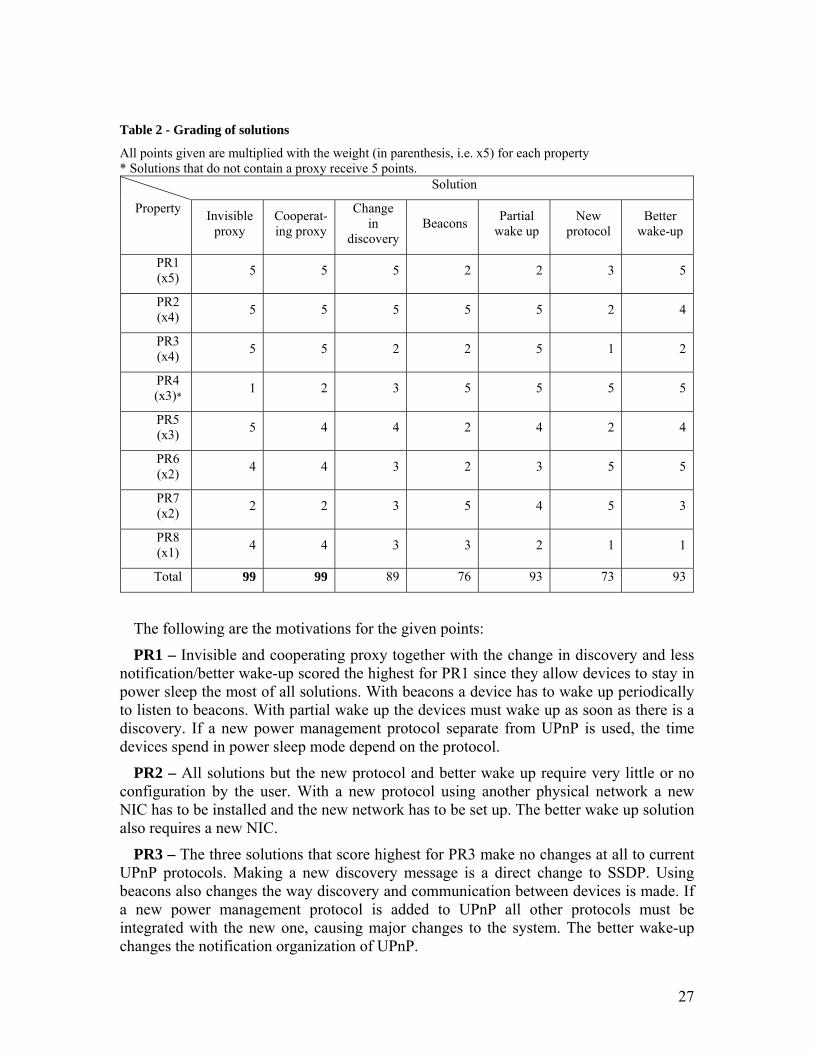
Table 2 - Grading of solutions
All points given are multiplied with the weight (in parenthesis, i.e. x5) for each property * Solutions that do not contain a proxy receive 5 points.
Solution
Property Invisible proxy
Cooperat-ing proxy
Change in
discovery Beacons Partial
wake up New
protocol Better
wake-up
PR1 (x5) 5 5 5 2 2 3 5
PR2 (x4) 5 5 5 5 5 2 4
PR3 (x4) 5 5 2 2 5 1 2
PR4 (x3)* 1 2 3 5 5 5 5
PR5 (x3) 5 4 4 2 4 2 4
PR6 (x2) 4 4 3 2 3 5 5
PR7 (x2) 2 2 3 5 4 5 3
PR8 (x1) 4 4 3 3 2 1 1
Total 99 99 89 76 93 73 93
The following are the motivations for the given points:
PR1 – Invisible and cooperating proxy together with the change in discovery and less notification/better wake-up scored the highest for PR1 since they allow devices to stay in power sleep the most of all solutions. With beacons a device has to wake up periodically to listen to beacons. With partial wake up the devices must wake up as soon as there is a discovery. If a new power management protocol separate from UPnP is used, the time devices spend in power sleep mode depend on the protocol.
PR2 – All solutions but the new protocol and better wake up require very little or no configuration by the user. With a new protocol using another physical network a new NIC has to be installed and the new network has to be set up. The better wake up solution also requires a new NIC.
PR3 – The three solutions that score highest for PR3 make no changes at all to current UPnP protocols. Making a new discovery message is a direct change to SSDP. Using beacons also changes the way discovery and communication between devices is made. If a new power management protocol is added to UPnP all other protocols must be integrated with the new one, causing major changes to the system. The better wake-up changes the notification organization of UPnP.

28
PR4 – The solutions that do not contain a proxy received 5 points because they obviously do not add any load to memory or CPU for a central device. The invisible proxy uses a lot of memory and CPU to keep track of the network at all times. The cooperating proxy and the new discovery message works in a more distributed manner.
PR5 –The invisible proxy does not add anything to end devices, while the cooperating proxy and the new discovery message make small additions since they work in a more distributed way. Partial wake up also makes small changes to end devices, while the changes made when using beacons or a new protocol are major, adding a large load on both CPU and memory. The better wake-up makes some changes to end devices with the new wake-up.
PR6 – The better wake-up will reduce the amount of traffic in the network since there are fewer notifications sent. Adding a new protocol that uses a separate physical network will not add any traffic load to the UPnP network. The cooperating and invisible proxies only add a couple of extra messages that are relatively small. Introducing a new discovery message is a bigger change, adding more new messages. With the partial wake up every message has to be preceded by a discovery introducing a higher network load. With beacons there is a higher network load than in the original UPnP network because the network is flooded with beacons periodically.
PR7 – The timing of the solution must be almost perfect if beacons are used. Using a new protocol will depend on the protocol used, but the timing with UPnP can be made efficient since wake up can be fast. The partial wake up also provides a fast wake up of devices. The three solutions using a proxy wake up devices using WOL, which means the sleeping device boots up when the message arrives. This might introduce delays in the network that are several seconds long.
PR8 – All proxy solutions require that the devices can enter power sleep mode and wake up on WOL, which adds a small cost to the end devices. When using a new discovery message the control points must store all services that are asleep, requiring extended memory capacity. The beacon solution also requires extra memory. The partial wake up and a new protocol mean major changes to hardware, adding a new cost for a more advanced hardware. The better wake-up also means changes to the hardware.
The two highest ranking solutions are the invisible and the cooperating proxy. Therefore these two solutions are chosen for implementation.
However the solution with the invisible proxy fails to fulfil one requirement. This still makes the solution acceptable, but less effective than the cooperating proxy, even though both solutions scored the same (see 3.1.2 for further discussion).
3.1.2 Discussion of cooperating and invisible proxy The two highest ranking solutions, the invisible and cooperating proxy, are similar, but
there are some important differences. The cooperating proxy is an addition to the invisible proxy, but this addition raises some new issues: crashed devices wake up of sleeping devices and changes to end devices.
Crashed devices: The whole idea of the invisible proxy is that no devices in the network are aware of the proxy. No devices communicate directly with the proxy (except for when the proxy makes a discovery from the network). The proxy promiscuously receives all packets in the network and after a certain time of inactivity from the device

29
(this time is defined by the user) it will assume that the device has entered power sleep mode. This is a very inexact method since there is no way of actually telling when the device has entered power sleep mode. Using this method means that when a device crashes or moves away from the network, (mobile devices connected to wireless networks might leave the network this way) the proxy will assume the device has entered power sleep mode. The proxy will not discover that the device has crashed until it tries to wake it up.
Using the cooperating proxy the problem of crashed devices is partly solved since the cooperating proxy communicates directly with devices in the network. The cooperating proxy is notified when a device enters power sleep mode and does not have to guess when this occurs. After a certain time of inactivity from a device in the network the cooperating proxy will remove the device from its cache since the device has left the network. This is the same procedure used in SSDP with expiring notifications. However, part of the problem still remains. The cooperating proxy cannot discover if a device crashes or leaves the network while it is in power sleep mode, since in this mode there is no communication between the device and the proxy. When the proxy tries to wake up the crashed device with a WOL it will not receive an update of the power management service and can then conclude that the device has left the network. Before this happens the crashed device will seem to be connected to the network since the proxy updates all notifications and answers all discoveries for the device.
Wake up of devices: Another problem with the invisible proxy is that it will not discover when a device has been woken up from power sleep mode until it receives a SSDP:alive. This means that the proxy cannot discover if the WOL was successful or not. This can be done by the cooperating proxy since the proxy is notified with an event when the power management service is updated.
Changes to end devices: The downside with the cooperating proxy is that end devices must implement the power management service to be able to enter power sleep mode. This means changing the software of the end device. UPnP devices that do not implement the power service can still function in the network. With the invisible proxy all that has to be done to allow UPnP devices to enter power sleep mode is to configure the device to activate WOL and power sleep. This means that the software does not have to be changed.
3.2 Design of the invisible proxy The FSM for the invisible proxy is presented in figure 9. Every message that uses the
HTTP protocol (all SSDP, SOAP and GENA messages) can be answered with a HTTP error code [31]. We have left out all error messages from the FSM to make it more readable. In the FSMs we have used a number of timers. All timers can be reset (RST):
Timer Service Startup (TSS) – The invisible proxy has a TSS that makes the proxy wait until a device that has been issued a WOL wakes up. Since there is no exact way for the proxy to find out when the device is booted up, it will use this timer. The length of this timer is 3 seconds. This is a reasonable time for a device to go from power sleep to fully powered up.

30
Timer Service Inactivity (TSI) – The invisible proxy and power management service has a TSI to decide when a service enters power sleep mode. The timer counts from the last activity from the device. When TSI expires for the proxy the proxy will start answering for the device. When TSI expires for a service the device will enter power sleep mode. The length of the timer is defined by the user when either of the applications is started.
Timer Send Notification (TSN) – Each service and proxy has a TSN to decide when it is time to send a SSDP:alive. The length of this timer is one third of the Cache-control: max-age value defined by the service in its notifications.
Timer Wait for Alive (TWA) – Each service and proxy has a TWA to decide whether a device has woken up or not. The timer starts when the proxy sends a WOL to the device. If this timer expires before the proxy receives a SSDP:alive from the device the proxy removes the device from its caches. The length of this timer is Cache-control: max-age value defined by the service in its notifications.
CHECK PROXY CACHE TCP P4
CHECK PROXY CACHE DISCOVERY P3
LISTENING P1
P01 Connect
SSDP:discover multicastRST TSI
P12 TSI timeout
PROXY DEVICE P2
P11 SSDP from S*
Update cache, RST TSI
P23 SSDP:discover / ARP from CP
P32a S in proxy cache
Discovery / ARP ans to CP
P32b S not in proxy cache
P24 TCP from CP***
P42 S not in proxy cache
P45 S in proxy cache
WOL to S, update proxy cacheRST TSS, RST TWA
P22 TSN timeout
SSDP:alive multicast spoof SRST TSN
P21 SSDP:alive from S**
Update cache, RST TSI
WAIT FOR ALIVE P5
P51a SSDP:alive from S
RST TSI
P55 TSS Timeout
Forward packet from CPP51b TWA timeout
Update cache
LISTENING P1
P01 Connect
SSDP:discover multicastRST TSI
P12 TSI timeout
PROXY DEVICE P2
P11 SSDP from S*
Update cache, RST TSI
P23 SSDP:discover / ARP from CP
P32a S in proxy cache
Discovery / ARP ans to CP
P32b S not in proxy cache
P24 TCP from CP***
P42 S not in proxy cacheP42 S not in proxy cache
P45 S in proxy cache
WOL to S, update proxy cacheRST TSS, RST TWA
P22 TSN timeout
SSDP:alive multicast spoof SRST TSN
P21 SSDP:alive from S**
Update cache, RST TSI
WAIT FOR ALIVE P5
P51a SSDP:alive from S
RST TSI
P55 TSS Timeout
Forward packet from CPP51b TWA timeout
Update cache
Figure 9 FSM for the invisible proxy
* SSDP message can be alive, byebye, or discovery answer. ** P21 is because the proxy took over too early or the service wakes up by itself. *** TCP SYN from CP will be resent if S does not wake up in time Proxy wakes up service when receiving any of these messages.

31
The states and transitions of the FSM are explained below:
LISTENING – In this state the proxy is in promiscuous mode. The proxy enters this state by connecting to the network (P01). When the connection is made the proxy makes a discovery of the network. In LISTENING state the proxy will react to incoming SSDP messages (P11) (SSDP:alive and SSDP:byebye). If a SSDP:alive is received the proxy will either update the service’s timestamp or add the service to the cache. If a SSDP:byebye is received the proxy will remove the device from its cache. If a service has been inactive for a certain time, defined by the user and used by TSI, the proxy will transition to state PROXY DEVICE (P12).
PROXY DEVICE – In this state the proxy assumes that a device has entered power sleep mode and therefore taken over the device’s responsibilities in the network. The proxy is still sniffing the network and processing packets as in the previous state, but now it also answers discoveries and processes TCP connections. If the proxy receives a discovery it transitions to state CHECK PROXY CACHE DISCOVERY (P23), and if a TCP connection is received it transitions to state CHECK PROXY CACHE TCP (P24). The transition P23 can also be made if the proxy receives an ARP. This has to be done because even though the UPnP cache is updated the ARP cache might have expired. Therefore the CP needs to use ARP to retrieve the Ethernet address of the service before a TCP connection can be made. However the proxy should not wake up the sleeping device when it receives an ARP because the ARP is no guarantee that a TCP connection will be made. When TSN expires the proxy will send a spoofed SSDP:alive (P22) to make sure that the sleeping service is not removed from other devices cache. If the proxy receives a SSDP:alive from a device that is supposed to be sleeping, it means the device is not sleeping at all. Therefore the proxy will remove the device from its proxy cache and move back to LISTENING state (P21).
CHECK PROXY CACHE DISCOVERY – If the proxy receives a discovery it checks if any of the sleeping devices should answer the discovery. If this is the case the proxy spoofs an answer to the discovery (P32a). Otherwise the proxy takes no action and transitions back to state PROXY DEVICE (P32b).
CHECK PROXY CACHE TCP – If an incoming TCP connection is received the proxy checks its proxy cache to see if the target of the TCP connection is in the proxy cache. If this is the case the proxy will send a WOL to wake up the device (P45). Otherwise the proxy takes no action and transitions back to state PROXY DEVICE (P42).
WAIT FOR ALIVE – When a WOL has been sent to wake up a sleeping device the proxy will wait until TSS expires to allow the device to boot up. Then the proxy will forward the TCP SYN that caused it to send the WOL (P55). If the proxy receives a SSDP:alive from the device it sent the WOL to the proxy will re-enter state LISTENING (P51a). If no SSDP:alive is received before TWA times out the proxy will remove the device from its caches and go to state LISTENING (P51b).

32
Figure 10 shows packet flow when the invisible proxy discovers the network. It sends out a SSDP:discover that is answered with a HTTP OK by all services in the network. Figure 11 shows packet flow when the invisible proxy takes over the responsibilities for a device that has entered power sleep mode. The proxy takes over when TSI expires. When a control point tries to discover the sleeping service, the proxy will spoof a HTTP OK. When the proxy tries to make a TCP connection to the sleeping service (e.g. requesting the XML schema) the proxy will wake the service up.
Service
1. SSDP:discover
Service
2. HTTP OK
3.HTTP OK
Proxy Service
1. SSDP:discover
Service
2. HTTP OK
3.HTTP OK
Proxy Service
1. SSDP:discover
Service
2. HTTP OK
3.HTTP OK
Proxy
Proxy Control point
Service in power sleep
2. SSDP:discover
ST = Printer
3. (Spoofed) HTTP OK
ST=Printer4. TCP SYN (intended for printer)
5.WOL
6. ForwardTCP SYN
1. TSI timeout
start proxy for Printer
7.TCP SYN ACKProxy Control point
Service in power sleep
2. SSDP:discover
ST = Printer
3. (Spoofed) HTTP OK
ST=Printer4. TCP SYN (intended for printer)
5.WOL
6. ForwardTCP SYN
1. TSI timeout
start proxy for Printer
Proxy Control point
Service in power sleep
2. SSDP:discover
ST = Printer
3. (Spoofed) HTTP OK
ST=Printer4. TCP SYN (intended for printer)
5.WOL
6. ForwardTCP SYN
1. TSI timeout
start proxy for Printer
7.TCP SYN ACK
Figure 10 - Invisible proxy discovers the network
Figure 11 - Invisible proxy takes over for sleeping service

33
3.3 Design of the cooperating proxy The cooperating proxy is an extension of the invisible proxy. All the states that were
kept from the old design are therefore presented in the FSM (figure 12) with smaller print and dotted lines. Just as in figure 9 we have left out the HTTP error messages.
The cooperating proxy communicates with devices in the network using events. For this to work every power management enabled device must implement a power management service. This service is basically one state variable with two states: SLEEP and POWER. The design of this service is shown with the FSM in figure 13. This design is an extension of the existing UPnP service presented in figure 3. There are several timers in the FSMs:
Timer Forward Packet (TFP) – The cooperating proxy has a TFP to be able to find out if a service that has been issued a WOL does not wake up (does not send a POWER event). This situation could occur if a device is disconnected from the network while in power sleep. The length of this timer is 3 seconds since this is the time before a new TCP SYN is sent.
Timer Process Discovery (TPD) – The cooperating proxy has a TPD that allows it to process discovery messages and get information about the network before the proxy starts with its main tasks. The length of this timer is 30 seconds, to make sure that all devices in the network have enough time to answer the discovery.
Timer Notification Expired (TNE) – The cooperating proxy has a TNE to check if a notification from a service has expired. The length of this timer is the Cache-control: max-age value defined by the service in its notifications.
Timer Send Notification (TSN) – Each service and proxy has a TSN to decide when it is time to send a SSDP:alive. The length of this timer is one third of the Cache-control: max-age value defined by the service in its notifications.
Timer Subscription Expired (TSE) – Each service has a TSN to decide when a subscription to the service’s events has expired. The length of this timer is the value of the Timeout header in the subscription request sent to the service.
Timer Service Inactivity (TSI) – The power management service has a TSI to decide when the service enters power sleep mode. The timer is reset with every activity from the device. When TSI expires for a service the device will enter power sleep mode. The length of the timer is defined by the user when the application is started.
All new states of the FSM are explained below.
PROCESS DISCOVERY – In this state the proxy discovers devices in the network. The state is entered when the proxy is turned on and the proxy sends a SSDP:discover, searching only for power management services (P06). If a HTTP OK is received the proxy sends a request for the service’s XML schema (P67) and moves on to process it. When the TPD timer times out the proxy is done with discovering the network and moves on to LISTENING state (P61).

34
PROCESS XML SCHEMA (P7) – In this state the proxy processes the received XML schema by parsing it and adding the device with all its services to its cache. When the processing is finished the proxy subscribes to events from the power management service and goes back to the PROCESS DISCOVERY state (P76).
LISTENING (P1) – In this state the proxy is in promiscuous mode. If a GENA event is received, notifying the proxy of a device powering down, the proxy will answer with a HTTP OK and enters PROXY DEVICE state (P12). If a GENA event is received, notifying the proxy of a device that is powering up, the proxy will answer the event with a HTTP OK and reenter the LISTENING state (P21). If the proxy wakes up a device using WOL it will not reenter LISTENING state until it has received a power up event from that device (P51a) or TFP times out (P51b). While the proxy is in LISTENING state it constantly checks if any device should be removed from the cache because its notification has expired (TNE times out) or a SSDP:byebye is received from the device (P11). The proxy can also receive an UNSUBSCRIBE message from a service, meaning that the subscription of power management events has been cancelled. If this happens the device is removed from the cache, since without being notified about power events the proxy will not be able to answer for the device (P11). In LISTENING state the proxy also listens for SSDP:alive messages from new power management services. If it receives
Figure 12 - FSM for the cooperating proxy
* The XML is only retrieved if S is not in the cache ** Only updates if S is in the cache *** TCP SYN from CP will be resent if S does not wake up in time Proxy wakes up service when receiving any of these messages.
LISTENING P1
P18 SSDP ALIVE from S NT=Power mgmt*
HTTP GET XML
CHECK PROXY CACHE TCP P4
PROXY DEVICE P2
CHECK PROXY CACHE DISCOVERY P3
P23 SSDP:discover / ARP from CP
P32a S in proxy cache
Discovery / ARP ans to CP
P32b S not in proxy cache
P24 TCP from CP***
P42 S not in proxy cache
P45 S in proxy cache
WOL to S, update proxy cache, RST TFP
P22 TSN timeout
SSDP:alive multicast spoof S
FORWARD PACKET
P5
P51a GENA, Power mgmt=POWER
HTTP OK, RST TNEForward packet from CP
P06 Connect
SSDP:discover ST=Power mgmt
RST TPD
PROCESS XML SCHEME P7
P76 XML processed
SUBSCRIBE Power mgmtRST TNE
P61 TPD timeoutP12 GENA, Power mgmt=SLEEP
HTTP OK, RST TNEUpdate proxy cache
P51b TFP timeout
Update cache
P21 GENA, Power mgmt=POWER
HTTP OK, RST TNEUpdate proxy cache
PROCESS XML SCHEME P8
PROCESS DISCOVERY P6
P67 HTTP OK
HTTP GET XML
P11 TNE timeoutUNSUBSCRIBE from SSSDP from S**
Update cacheRST TNE
P81 XML processed
SUBSCRIBE Power mgmtRST TNE
LISTENING P1
P18 SSDP ALIVE from S NT=Power mgmt*
HTTP GET XML
LISTENING P1
P18 SSDP ALIVE from S NT=Power mgmt*
HTTP GET XML
CHECK PROXY CACHE TCP P4
PROXY DEVICE P2
CHECK PROXY CACHE DISCOVERY P3
P23 SSDP:discover / ARP from CP
P32a S in proxy cache
Discovery / ARP ans to CP
P32b S not in proxy cache
P24 TCP from CP***
P42 S not in proxy cache
P45 S in proxy cache
WOL to S, update proxy cache, RST TFP
P22 TSN timeout
SSDP:alive multicast spoof S
FORWARD PACKET
P5
CHECK PROXY CACHE TCP P4
PROXY DEVICE P2
CHECK PROXY CACHE DISCOVERY P3
P23 SSDP:discover / ARP from CP
P32a S in proxy cache
Discovery / ARP ans to CP
P32b S not in proxy cache
P24 TCP from CP***
P42 S not in proxy cacheP42 S not in proxy cache
P45 S in proxy cache
WOL to S, update proxy cache, RST TFP
P22 TSN timeout
SSDP:alive multicast spoof S
FORWARD PACKET
P5
FORWARD PACKET
P5
P51a GENA, Power mgmt=POWER
HTTP OK, RST TNEForward packet from CP
P06 Connect
SSDP:discover ST=Power mgmt
RST TPD
PROCESS XML SCHEME P7
P76 XML processed
SUBSCRIBE Power mgmtRST TNE
P61 TPD timeoutP12 GENA, Power mgmt=SLEEP
HTTP OK, RST TNEUpdate proxy cache
P51b TFP timeout
Update cache
P21 GENA, Power mgmt=POWER
HTTP OK, RST TNEUpdate proxy cache
PROCESS XML SCHEME P8
PROCESS DISCOVERY P6
P67 HTTP OK
HTTP GET XML
P11 TNE timeoutUNSUBSCRIBE from SSSDP from S**
Update cacheRST TNE
P81 XML processed
SUBSCRIBE Power mgmtRST TNE

35
a SSDP:alive message, the proxy retrieves the device’s XML schema and transitions to state PROCESS XML SCHEMA (P18).
PROCESS XML SCHEMA (P8) – This state is very similar to state P7. The only difference is that when the XML schema has been processed the proxy reenters LISTENING state (P81).
All new states of the power management service are described below:
SHUTTING DOWN – When TSI expires the service will change the value of the state variable to SLEEP and by that sending out an event to the proxy and all other devices that subscribe to this event (S15). The service enters SHUTTING DOWN state, and when the device is done shutting down it will enter POWER SLEEP state (S56).
POWER SLEEP – The device stays in POWER SLEEP state until it receives a WOL or is woken by an internal routine (a timer or manual wake up by a user). When the device is ordered to wake up it will enter START UP state (S67).
START UP – Once the device is completely powered up again it will change the state variable back to POWER, notifying all subscribers about the change of state. Once the state is changed the service reenters LISTENING state (S71).
In the design of the cooperating proxy no alternation of control points is needed. If a
SHUTTING DOWN S5
S15 TSI timeout
Power mgmt = SLEEP, notify subscribers
POWER SLEEP S6
S56 Shut down
S67 WOL from P / manual wake upS71 Startup complete
Power mgmt = POWER, notify subscribersRST TSI
START UP S7
LISTENINGS1
S01 Connect
SSDP:alive multicast, RST TSN
RST TSI S12 SOAPAction from CP
S21 Action done
Action response to CP
RST TSI
SERVICE INVOKESS ACTION S2
S11b SSDP:discover from CP
Discovery ans to CP
LEAVE NETWORK
S3
S13 Disconnect
SSDP:byebye multicast
WAIT FOR RESPONSES S4
S14 Change of state
NOTIFY to all subscribers
S41 HTTP OK from CP/ 30 sec timeout
S11e TSE timeout
Update subscription list
S11a HTTP GET from CP
XML scheme to CP
S11c TSN timeout
SSDP:alive multicastRST TSN
S11d UN/SUBSCRIBE from CP*
Update subscription list HTTP OK to CP, RST TSE
SHUTTING DOWN S5
S15 TSI timeout
Power mgmt = SLEEP, notify subscribers
POWER SLEEP S6
S56 Shut down
S67 WOL from P / manual wake upS71 Startup complete
Power mgmt = POWER, notify subscribersRST TSI
START UP S7
LISTENINGS1
S01 Connect
SSDP:alive multicast, RST TSN
RST TSI S12 SOAPAction from CP
S21 Action done
Action response to CP
RST TSI
SERVICE INVOKESS ACTION S2
SERVICE INVOKESS ACTION S2
S11b SSDP:discover from CP
Discovery ans to CP
LEAVE NETWORK
S3
S13 Disconnect
SSDP:byebye multicast
LEAVE NETWORK
S3
S13 Disconnect
SSDP:byebye multicast
WAIT FOR RESPONSES S4
S14 Change of state
NOTIFY to all subscribers
S41 HTTP OK from CP/ 30 sec timeout
WAIT FOR RESPONSES S4WAIT FOR RESPONSES S4
S14 Change of state
NOTIFY to all subscribers
S41 HTTP OK from CP/ 30 sec timeout
S11e TSE timeout
Update subscription list
S11a HTTP GET from CP
XML scheme to CP
S11c TSN timeout
SSDP:alive multicastRST TSN
S11d UN/SUBSCRIBE from CP*
Update subscription list HTTP OK to CP, RST TSE
Figure 13 - FSM for the UPnP power management service
*Can be new subscription, subscription renewal and unsubscription

36
device that runs a control point application wants to enter power sleep mode it has to have a power management service, so that it can communicate with the proxy.
Figure 14 shows the packet flow when the cooperating proxy discovers all power management services in the network. The proxy retrieves the XML schema from each power management service that answers the discovery. Devices in the network that do not have the power management service do not answer to the discovery.
Figure 15 shows the packet flow when a power management service enters power sleep mode and notifies the proxy. The proxy then takes over the service’s responsibilities. When a control point tries to discover the service, the proxy will spoof a HTTP OK. When a control point tries to establish a TCP connection to the service (e.g. retrieving the XML schema) the proxy will wake up the sleeping device and then forward the TCP SYN packet so that a TCP connection between the control point and service can be established.
Figure 14 - Cooperating proxy discovers the network
Proxy Service with power management
1. SSDP:discoverST= Powermgmt
Service without powermgmt
2. HTTP OK
3. GET XML
4. XML Description
Proxy Service with power management
1. SSDP:discoverST= Powermgmt
Service without powermgmt
2. HTTP OK
3. GET XML
4. XML Description
Proxy Service with power management
1. SSDP:discoverST= Powermgmt
Service without powermgmt
2. HTTP OK
3. GET XML
4. XML Description
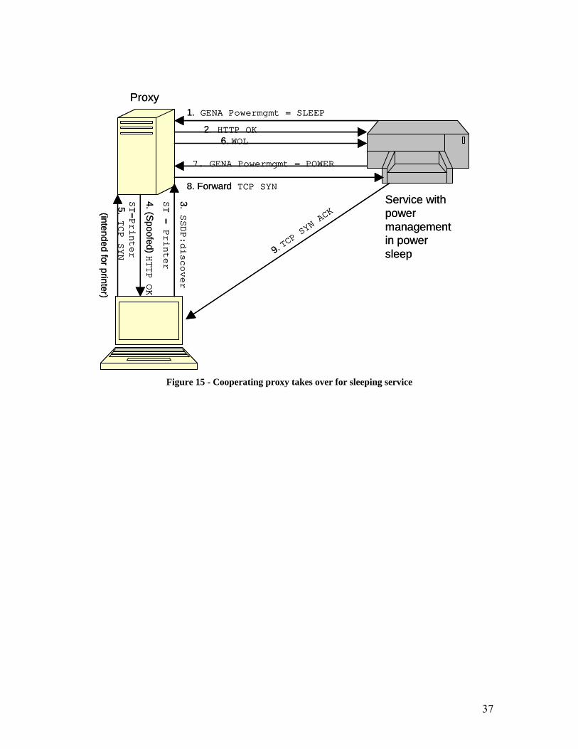
37
Proxy
Service with power management in power sleep
3.SSDP:discover
ST = Printer
4. (Spoofed) HTTP OK
ST=Printer
5.TCP SYN
(intended for printer)
1. GENA Powermgmt = SLEEP
2. HTTP OK6. WOL
8. Forward TCP SYN
9. TCP SYN ACK
7. GENA Powermgmt = POWER
Proxy
Service with power management in power sleep
3.SSDP:discover
ST = Printer
4. (Spoofed) HTTP OK
ST=Printer
5.TCP SYN
(intended for printer)
1. GENA Powermgmt = SLEEP
2. HTTP OK6. WOL
8. Forward TCP SYN
9. TCP SYN ACK
7. GENA Powermgmt = POWER
Figure 15 - Cooperating proxy takes over for sleeping service

38
4 Implementation of solutions
Here the implementations of two selected solutions are described in detail. The tools used are described and motivated. The proof of concepts made are also described in this chapter.
4.1 Implementation tools In the proxy solutions it has to be possible to spoof complete packets on the network.
Since high level programming languages make it complicated to have total control over incoming and outgoing packets C and a network library called Netwib [29] are used during the implementation. Netwib offers a wide range of functions for address conversion, TCP and UDP, clients and servers, spoofing and sniffing. In Netwib’s documentation Bloodshed’s Dev-C++ [30] is recommended as development platform. Since the program is free and worked well on the development platform it is used during the implementation. Dev-C++ has support for debugging, class browsing, project managing and other important functionality. Together Dev-C++ and Netwib makes it possible to implement the solutions within the timeframe of this thesis which otherwise might not had been the case.
To test and evaluate the solutions Ethereal [24] and Intel Tools for UPnP Technologies [23] are used. Ethereal is a powerful network packet analyzer. It is used to sniff and check packets. Intel’s UPnP Tools contains several valuable UPnP tools including a device spy, a device sniffer and some simple UPnP devices such as the Network Light.
4.2 Proof of concept To see that it is possible to implement the solution four proof of concepts are
implemented. The following four proof of concepts are made:
• wake-up of devices
• receiving and sending discovery intended for other devices
• sending of advertisement spoofed from other device
• implementing an UPnP device.
The C code for all proof of concepts is available for download at [21].
4.2.1 Wake-up of devices To be able to use power sleep a device has to be able to wake up again. In order to
accomplish this Wake on LAN (WOL) [22] is used. The WOL frame is a packet addressed to the Ethernet broadcast address (FF:FF:FF:FF:FF:FF) followed by the Ethernet address of the device that is going to be woken up, repeated sixteen times. To be able to send the WOL an UDP multicast socket to the IP broadcast address (255.255.255.255) is opened. This program was tested and it managed to wake up a WOL enabled computer from power sleep mode.

39
4.2.2 Sending of advertisement spoofed from other device In order to prevent notifications from expiring SSDP:alive messages must be
spoofed.
In this proof of concept a hard coded SSDP:alive message is used. The packet is then spoofed, using Netwib’s spoof functions, to the SSDP broadcast address (239.255.255.250:1900). The packet is verified using Ethereal [24]. The packet is also captured with Intel’s Device Sniffer [23] which only captures UPnP related packets.
4.2.3 Receiving and answering discovery intended for other device In the invisible proxy solution it is important to be able to receive and answer
discovery messages intended for sleeping devices. The first step is to sniff traffic intended for the IP address the proxy wants to answer for. Since discovery messages are UDP packets and Netwib offers a possibility to filter captured packets, all packets but UPD packets are filtered out.
When a packet is received it is checked whether it is a SSDP:discover and should be answered or not. Since it is known that the first eight bits of the HTTP header of a discovery is “M-SEARCH“ (see A.2) these bits are compared with a hard coded string. If the strings match, it can be concluded that the message is a discovery and should be answered. To respond to the discovery the source Ethernet and IP addresses of the incoming packet are parsed out and then a response with a HTTP-OK from the Ethernet and IP addresses of the sleeping device is sent. In the proof of concept the complete HTTP-OK message is hard coded as a copy of a HTTP-OK message sent out by the Intel UPnP Network Light [23]. The packet is verified using Ethereal.
4.2.4 Implementation of a UPnP power management service In the design of the cooperating proxy, the proxy communicates with devices using
eventing. This means that when the proxy finds a power management enabled device it subscribes to power management events, and whenever the device enters or exits power sleep mode the proxy is notified by an event. To enable this communication every device that has power management enabled must have a power management service with a state variable that contains the value of the device’s current power mode (SLEEP or POWER). This service was implemented as a proof of concept. The service has the Uniformed Resource Name (URN) schemas-power:service:Powermgmt. The service has one state variable power that can have the value true if the device is powered up or false if the device is in power sleep mode. The service has one action, GetPowerStatus, which will return the value of the variable power.
4.3 Implementation of the invisible proxy The three proof of concepts for waking up devices, receiving and answering discovery
messages for other devices and sending advertisement for other devices are the foundation for the invisible proxy. These proof of concepts covers the most important functionality of the invisible proxy.
In this proxy two caches are used, one for all UPnP devices on the network (device cache) and one for all the devices that are assumed to be sleeping and the proxy wants to answer for (proxy cache). A simple data structure is used to store information about

40
devices and services in the caches. The data structure for a device contains the IP address, Ethernet address, server name (see A.3.2), location (see A.1.5), time for the last activity from the device, a boolean variable that tells if the device is in the proxy cache or not and a list with all services that the device has. The structure for a service contains the Unique Service Name (USN) (see A.1.2), the search target for the service (see A.2.3), the time when the last SSDP:alive was sent, the timeout time (see A.1.4) and the port for the service. This structure is described in figure 16.
Device Cache
All devices on the network
UPnP Device
UPnP Device
UPnP Device
UPnP Device
Proxy CacheAll devices the proxy is answering for
UPnP Device
UPnP Device
UPnP Device
UPnP Device
Device Cache
All devices on the network
UPnP Device
UPnP Device
UPnP Device
UPnP Device
Proxy CacheAll devices the proxy is answering for
UPnP Device
UPnP Device
UPnP Device
UPnP Device
UPnP DeviceName
ip
eth
service
server
location
last_activity
ServiceName
st
usn
Last_notification
timeout
port
Description
IP address
Ethernet address
All services of the device
Server name
Location
Time for last activity from the device
Description
Search Target
Unique Service Name
Time when last SSDP:alivewas sent
Notification timeout
Port for the service
Service
Service
Service
Service
Figure 16 - Overview of the data structure in the invisible and cooperating proxies
The functionality of the proxy is maintained by three different threads: the main thread, proxy cache update thread, and notify thread. These threads are described in figure 17.
The main thread starts by sending out a SSDP:discover to discover all UPnP devices in the network and to build the initial device cache. When this is done the main thread starts the other two threads and goes into the main loop. In the main loop the proxy promiscuously receives all TCP, UDP and ARP packets on the network. Once a packet is received, the destination IP address is checked against the IP addresses of all the devices in the proxy cache plus the SSDP broadcast address (239.255.255.250). If the proxy receives an ARP request for a device in the proxy cache it answers with a spoofed ARP-reply for that device. If a received packet is a TCP packet for a device in the proxy cache the proxy sends a WOL to that device and wakes it up. If the packet is an UDP packet the proxy checks whether it is a SSDP:discover, a SSDP:alive or a SSDP:byebye (all other packets are discarded). If it is a SSDP:discover for a service that is in the proxy cache (i.e. the service’s device is in the cache) the proxy responds with a spoofed HTTP-OK for that service. If the packet is a SSDP:alive from a device in the proxy cache the proxy concludes that the device is not in power sleep and is therefore removed from the proxy cache. If the packet is a SSDP:byebye the device is removed from the device cache.
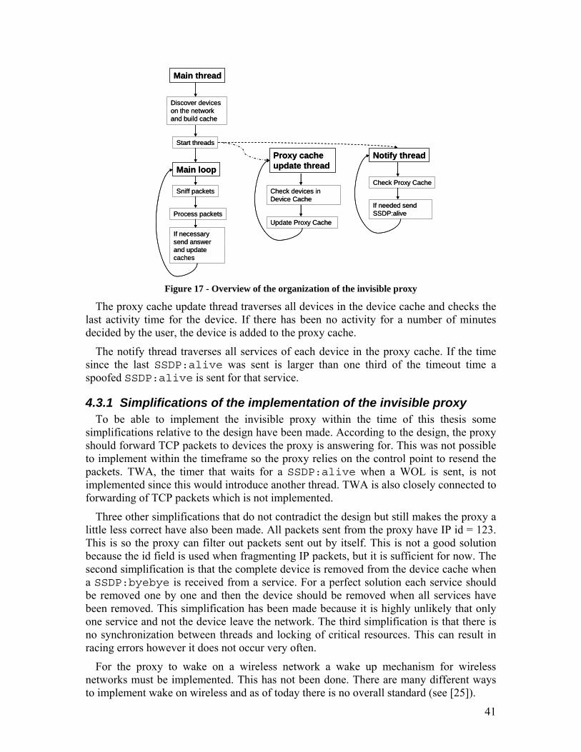
41
Main thread
Proxy cache update thread
Notify thread
Discover devices on the network and build cache
Start threads
Main loop
Sniff packets
Process packets
If necessary send answer and update caches
Check devices in Device Cache
Update Proxy Cache
Check Proxy Cache
If needed send SSDP:alive
Main thread
Proxy cache update thread
Notify thread
Discover devices on the network and build cache
Start threads
Main loop
Sniff packets
Process packets
If necessary send answer and update caches
Check devices in Device Cache
Update Proxy Cache
Check Proxy Cache
If needed send SSDP:alive
Figure 17 - Overview of the organization of the invisible proxy
The proxy cache update thread traverses all devices in the device cache and checks the last activity time for the device. If there has been no activity for a number of minutes decided by the user, the device is added to the proxy cache.
The notify thread traverses all services of each device in the proxy cache. If the time since the last SSDP:alive was sent is larger than one third of the timeout time a spoofed SSDP:alive is sent for that service.
4.3.1 Simplifications of the implementation of the invisible proxy To be able to implement the invisible proxy within the time of this thesis some
simplifications relative to the design have been made. According to the design, the proxy should forward TCP packets to devices the proxy is answering for. This was not possible to implement within the timeframe so the proxy relies on the control point to resend the packets. TWA, the timer that waits for a SSDP:alive when a WOL is sent, is not implemented since this would introduce another thread. TWA is also closely connected to forwarding of TCP packets which is not implemented.
Three other simplifications that do not contradict the design but still makes the proxy a little less correct have also been made. All packets sent from the proxy have IP id = 123. This is so the proxy can filter out packets sent out by itself. This is not a good solution because the id field is used when fragmenting IP packets, but it is sufficient for now. The second simplification is that the complete device is removed from the device cache when a SSDP:byebye is received from a service. For a perfect solution each service should be removed one by one and then the device should be removed when all services have been removed. This simplification has been made because it is highly unlikely that only one service and not the device leave the network. The third simplification is that there is no synchronization between threads and locking of critical resources. This can result in racing errors however it does not occur very often.
For the proxy to wake on a wireless network a wake up mechanism for wireless networks must be implemented. This has not been done. There are many different ways to implement wake on wireless and as of today there is no overall standard (see [25]).

42
4.4 Implementation of cooperating proxy The cooperating proxy builds on the invisible proxy. The caches of the cooperating
proxy have the same structure as in the invisible proxy, and are shown in figure 16.
The cooperation proxy’s functionality is handled by four threads, the main thread, the cache update thread, the notify thread and the read event socket thread. This is shown in figure 18.
The main thread has the same functionality as in the invisible proxy. The only difference is how the initial cache is built. The thread starts by sending out SSDP:discover for all power management services and then requests the XML schema for all devices that answer the discovery. The XML schema is then parsed and the proxy adds the device and its services to the device cache. This means that only devices with power management services will be added to the device cache instead of all devices on the network as in the case of the invisible proxy. When a device is added to the device cache the proxy also sends a subscription request for the power state variable in the power management service. After building the initial device cache the main thread starts the other threads and goes into the main loop. The functionality of the main loop is the same as in the invisible proxy (see 4.3).
The update cache thread has a different duty than the corresponding thread in the invisible proxy. Instead of copying devices from the device cache into the proxy cache, the update cache thread checks the last received SSDP:alive from the power management service. If the notification has expired, the device is removed from the device cache.
The notification thread has the same functionality as the one in the invisible proxy. It sends out spoofed SSDP:alive for devices in the proxy cache.
The read event socket thread reads incoming events from the power management services the proxy subscribes to. When an event is received it is parsed to see if the device is powering up or down. If the device if powering down it is copied into the proxy cache and the proxy starts answering for the device. If the device is powering up it is removed from the proxy cache. In this case the device still remains in the device cache and the proxy continues listening to events from the device’s power management service.

43
Figure 18 - Overview of the organization of the cooperating proxy
4.4.1 Simplifications of the implementation of the cooperating proxy In addition to the simplifications made in the invisible proxy (see 4.3.1) the
implementation of the cooperating proxy contains one more simplification relative to the design. According to the design a service can unsubscribe the proxy from the power management service. In our implementation the UNSUBSCRIBE messages are discarded. This is because there is no proper documentation of what an unsubscribe message from a service look like. It is also unlikely that a service needs to unsubscribe from the proxy.
The timer that discovers if a device that has been issued a WOL really wakes up or has left the network while in power sleep mode (TFP, figure 12 transition P51b) has not been implemented. Therefore the cooperating proxy will be completely dependent on the event sent from the service to notify the service that the service is powered up. The implementation was not made because it would introduce a new thread to the architecture. None of the other threads can be stopped for 10 seconds to check whether the device wakes up or not. An implementation of the timer is possible, but since this situation is relatively unlikely to occur we have not implemented it.
Main Thread
Discover power management services on the network and build cache
Start threads
Main loop
Sniff packets
Process packets
If necessary answer and update caches
Cache update thread
Check devices in Device cache
Update Device cache
Notification thread
Check Proxy cache
If necessary send SSDP:alive
Read event socket thread
Read and parse incoming events
Update Proxy cache

44
5 Validation
To show that the implementation of the invisible and cooperating proxy follows the design presented in previous chapters the following test cases have been constructed to cover all requirements. All test cases were not executed due to lack of equipment.
5.1 Description of Test Bed
In the design and execution of the test cases several tools are used. In this section detailed information about the equipment (hardware and software) used is provided. Figure 19 shows the setup of the test environment described in the next sections.
5.1.1 Software Several different software tools and applications are used to create an UPnP network,
control the network and check the packet flow. All software uses Windows XP as platform. For the software to work properly all firewalls are turned off. The software that is validated, that is the implementation of the invisible and cooperating proxy, can be downloaded from [21]. In this validation the version for the invisible proxy is 1.1 and the cooperating proxy is 1.0.
When validating the cooperating proxy we use the UPnP power management service that was implemented as a proof of concept (see section 4.2.4). The power management service is a simple UPnP device with a single service that shows whether the device is in power sleep mode or not. This software can be downloaded from [21].
Figure 19 - Test environment
Proxy131.247.2.17
Device spy + Ethereal
131.247.2.16
Device spy131.247.2.24
Lightbulb + power
management service
131.247.2.8
LAN
Proxy131.247.2.17
Device spy + Ethereal
131.247.2.16
Device spy131.247.2.24
Lightbulb + power
management service
131.247.2.8
LAN

45
To simulate UPnP devices in the network Intel’s Lightbulb for UPnP Technologies version 1.0.1768.24086 is used. The lightbulb application is a simple UPnP device with a lightbulb interface that can be switched on and off and dimmed using an UPnP control point. This software can be downloaded from [23].
To control UPnP devices in the network Intel’s Device Spy for UPnP Technologies version 1.3.1768.24086 is used. The device spy can be used as a manual control point. This means that the spy finds all available UPnP devices in the network and allows the user to change state variables and invoke actions on each device. The device spy is a suitable application for controlling the lightbulb and the power management service. The device spy can discover new devices in the network, subscribe to events, invoke actions and read SSDP:alive and SSDP:byebye messages. This software can be downloaded from [23].
To sniff packets in the network while executing the test cases the Ethereal Network Protocol Analyzer version 0.10.8 is used. Ethereal can be downloaded from [24].
5.1.2 Computers In the execution of the test cases four different computers are used. The computers
have similar tasks in each test case. Table 3 describes the computers: model, their tasks, operating system, CPU speed and memory. Table 3 - Computers used in validation
* The Gateway computer is used not because of its higher performance but because this was the only available computer that has WOL enabled.
Model Tasks OS CPU Memory
Dell Dimension XPS T700r
Run proxy software Windows XP Pro, SP2
Intel PIII, 700 MHz
256 MB
Dell Dimension XPS T700r
Run Ethernet sniffer and device spy
Windows XP Pro, SP2
Intel PIII, 870 MHz
384 MB
Dell Dimension XPS B866r
Run device spy Windows XP Pro, SP2
Intel PIII, 870 MHz
128 MB
Gateway 7422GZ
Run lightbulb and power management service
Windows XP Home, SP2
AMD Athlon 64, 2.2 GHz *
1024 MB
5.1.3 Network When executing test cases all equipment is connected to the same 100 Mb/sec Ethernet
LAN using a five port workgroup hub from Linksys, model EFAH05W. The hub provides a controlled environment where no other computers than the ones used in the testcase will produce network traffic. This makes the packets captured in Ethereal easier to analyze and gives the tester control over the network traffic.
5.2 Validation of the invisible proxy In the test cases for the invisible proxy Intel’s Micro Light (L), two of Intel’s device
spies (DS1 and DS2), the implementation of the invisible proxy (InvP) and the Ethereal sniffer are used.

46
5.2.1 Test cases Below are the test cases that validates that the invisible proxy fulfills all requirements
from section 2.1. Test case T4 to T6 will not be executed because lack of equipment (T6 will only pass if all other test cases pass). Test case T2 will partly fail because we have not implemented the forwarding of TCP SYN. That means that DS2 will try to make a TCP connection to L, but L will never answer the connection. Therefore L will not be shown in DS2 until a SSDP:alive from L is sent out. This problem is discussed in section 4.3.1. Test case T3a and T3b will fail. This is a known problem with the InvP. If a device crashes InvP will assume it has entered power sleep mode and start answering for it. This issue is discussed in section 3.1.2 and table 1.
T1, requirement R1 Set up a network with three computers: one that runs InvP, one that runs L and
one that runs DS1 and the Ethereal sniffer. The computer that runs L is WOL enabled and enters power sleep mode after 1 minute.
Initiate an Ethereal sniff session. Start L and DS1. DS1 finds L. Start InvP with the timeout set to 1 minute.
Check that InvP finds L and adds it to its device cache. Test that L can be controlled using DS1.
Wait until the computer that runs L enters power sleep mode. Make sure that L is still visible in DS1.
Wait until InvP discovers that L is asleep and moves the device to its proxy cache.
Make sure that L is still visible in DS1. Wait until the last notification from L times out (120 seconds). Check that the InvP spoofs at least 3 notifications during this time. Make sure that L is still visible in DS1.
Try invoking an action on L using DS1. Check that InvP notices the incoming TCP connection and wakes up the
sleeping device. Make sure that L now can be controlled using DS1. Check that InvP removes the device from its proxy cache and stops spoofing messages.
Check the packet flow captured by the Ethereal sniffer and make sure that all packets are correct and are sent to the correct addresses.
T2, requirement R2 Set up network with four computers: one with InvP, one with L, one with DS1
and Ethereal sniffer and one with only DS2. The computer that runs L is WOL enabled and enters power sleep mode after 1 minute.
Initiate an Ethereal sniff session. Start L and DS1 and make sure DS1 finds L. Start InvP with the timeout set to 1 minute.
Make sure L is discovered by InvP and added to the device cache. Let DS1 subscribe to events from L. Wait until the computer that runs L goes into power sleep mode. Wait until the
last notification from L times out. Make sure SSDP:alive is spoofed and that L does not disappear from DS1.
Start DS2. DS2 will discover L and request its XML schema. Check that the proxy wakes up L. Check that L is shown in the DS2 after it has
booted up. Wait until L enters power sleep mode again. Let DS1 unsubscribe from L.

47
Check that the proxy wakes up L and that the unsubscription can be processed successfully.
Let L leave the network. Make sure SSDP:byebye is sent and that L disappears from DS1 and DS2. Check the packet flow captured by the Ethereal sniffer and make sure that all
packets are correct and are sent to the correct addresses. T3a, requirement R3
Set up a network with three computers: one that runs InvP, one that runs L and one that runs DS1 and the Ethereal sniffer. The computer that runs L is WOL enabled and enters power sleep mode after 1 minute.
Initiate an Ethereal sniff session. Start L and DS1. DS1 finds L. Start InvP with the timeout set to 1 minute.
Check that InvP finds L and adds it to its device cache. Test that L can be controlled using DS1.
Disconnect the computer that runs L from the network, without exiting the application.
Check that L is still visible in DS1. Wait until the InvP removes the disconnected device from its device cache and
L is no longer visible in DS1. Check the packet flow captured by the Ethereal sniffer and make sure that all
packets are correct and are sent to the correct addresses. T3b, requirement R3
Set up a network with three computers: one that runs InvP, one that runs L and one that runs DS1 and the Ethereal sniffer. The computer that runs L is WOL enabled and enters power sleep mode after 1 minute.
Initiate an Ethereal sniff session. Start L and DS1. DS1 finds L. Start InvP with the timeout set to 1 minute.
Check that InvP finds L and adds it to its device cache. Test that L can be controlled using DS1.
Wait until the computer that runs L enters power sleep mode. Make sure that L is still visible in the DS1.
Wait until InvP discovers that L is asleep and moves the device to its proxy cache.
Make sure that L is still visible in DS1. Wait until the last notification from L times out (120 seconds). Check that the InvP spoofs at least 3 notifications during this time. Make sure
that L is still visible in DS1. Disconnect the computer that runs L from the network. Check that L is still visible in DS1.
Try invoking an action on L using DS1. Check that InvP sends a WOL to L, does not get an answer and removes L from
both the proxy cache and device cache. Check the packet flow captured by the Ethereal sniffer and make sure that all
packets are correct and are sent to the correct addresses. T4, requirement R4
Repeat test cases T1, T2 and T3 and using WiFi (IEEE 802.11 b/g) instead of Ethernet.

48
T5, requirement R5 Repeat test cases T1, T2, T3 and T4 with at least 100 UPnP devices, except for
the ones used for actual testing, connected to the network. Use different kind of devices from different manufacturers.
T6, requirement R6 Requirement R6 is fulfilled by the fact that all other test cases pass.
5.2.2 Execution of test cases Test cases T1-T3b were executed.
T1 – Passed
Figure 20 shows a screenshot of the Ethereal sniffer with a trace of testcase T1. Packets 94-135 are notifications spoofed by the proxy. Packet 138 shows the TCP SYN from DS1. The proxy sends out a WOL, packet 140. Packets 143-152 are notifications from the woken service. The TCP connection between DS1 and L is not established until packet 162.
T2 – Failed. The test case failed because DS2 did not discover L until a SSDP:alive was received. This behaviour was expected (see 5.2.1). The test case had to be rerun several times because DS1 tries to renew its subscription while L is in power sleep mode, causing the proxy to send a WOL to L. The subscription time cannot be controlled using
Figure 20 - Test case T1, invisible proxy

49
DS1. We noticed that the proxy froze once or twice while executing this test case. This was due to the short timeouts (120 seconds Cache-control for L and 1 min proxy timeout). This resulted in racing errors amongst threads in the InvP implementation. Figure 21 shows a screenshot of the Ethereal sniffer with a trace of testcase T2. Packets 120-129 are parts of a TCP connection carrying the subscription from DS1 to L. Packets 149-153 are spoofed from the proxy. Packet 154-155 are the SSDP:discover sent from DS2. What happens next is not caught by Ethereal. The proxy answers the discovery with a HTTP OK, DS2 requests the XML schema and the proxy sends a WOL to L that is shown in packet 157. The service wakes up and packets 158-167 are sent from L. The last TCP connection is a subscription update from DS1 to L.
T3a – Failed. This test case failed because InvP cannot discover if a device has been disconnected from the network. Instead of removing the device from its cache InvP starts answering for it. This behaviour was expected and is discussed in section 5.2.1. No screenshot is presented because the process of a device crashing is not seen in a packet trace.
T3b – Failed. This test case failed for the same reason as above. No screenshot is presented because the process of a device crashing is not seen in a packet trace.
Figure 21 Test case T2, invisible proxy

50
5.3 Validation of the cooperating proxy In the test cases for the invisible proxy Intel’s Micro Light (L), the power management
service (PMS), two of Intel’s device spies (DS1 and DS2), the implementation of the cooperating proxy (CoopP) and the Ethereal sniffer are used.
5.3.1 Test cases Below are the test cases that validate that the cooperating proxy fulfills all
requirements from section 2.1. Test case T4 to T6 will not be executed because lack of equipment (T6 will only pass if all other test cases pass). Test case T2 will partly fail because we have not implemented the forwarding of TCP SYN. This means that DS2 will try to make a TCP connection to L, but L will never answer the connection. Therefore L will not be shown in DS2 until a SSDP:alive from L is sent out. This problem is discussed in section 4.3.1. Test case T3b will fail because the timer that is supposed to discover that a device has left the network while in power sleep mode (TFP, figure 12, transition P51b) has not been implemented. This is discussed in section 4.4.1. Notice that in test case T2 L and PMS must have the same Cache-control: max-age value.
T1, requirement R1 Set up a network with three computers: one that runs the CoopP, one that runs
PMS and one that runs DS1 and the Ethereal sniffer. The computer that runs the PMS is WOL enabled and enters power sleep mode after 1 minute.
Initiate an Ethereal sniff session. Start PMS and DS1. DS1 finds PMS. Start CoopP.
Check that CoopP finds PMS and adds it to its device cache. Test that PMS can be controlled using the DS1.
Wait until the computer that runs PMS enters power sleep mode. Check that CoopP receives an event from PMS and moves it to its proxy cache.
Make sure that PMS is still visible in DS1. Wait until the last notification from PMS times out (120 seconds). Check that the CoopP spoofs at least 3 notifications during this time. Make sure
that PMS is still visible in DS1 although the notification should have timed out. Try invoking an action on PMS using DS1. Check that CoopP notices the incoming TCP connection and wakes up the
sleeping device. PMS sends an event to the CoopP, which in turn removes the device from its proxy cache and stops spoofing messages.
Make sure that PMS now can be controlled using DS1. Check the packet flow captured by the Ethereal sniffer and make sure that all
packets are correct and are sent to the correct addresses. T2, requirement R2
Set up network with four computers: one with CoopP, one with L and PMS, one with DS1 and Ethereal sniffer and one with only DS2. The computer that runs L is WOL enabled and enters power sleep mode after 1 minute.
Initiate an Ethereal sniff session. Start L, PMS and DS1. Make sure DS1 finds L and PMS. Start CoopP and make sure PMS is
discovered by CoopP and added to the device cache and that CoopP subscribes to changes in PMS.

51
Check that L is added to the device cache when the first SSDP:alive from L is received (L will not answer SSDP:discover from CoopP because it is not a power management service). Let DS1 subscribe to events from L.
Let the computer that runs L enter power sleep and make sure an event is sent from PMS to CoopP.
Wait until the last notification from L times out. Make sure SSDP:alive is spoofed and that L does not disappear from DS1.
Start DS2. DS2 will discover L and request its XML schema. Check that the proxy wakes up L and that PMS notifies the proxy of the change.
Check that L is shown in DS2 after it has booted up. Wait until L enters power sleep mode again. Let DS1 unsubscribe from L. Check that the proxy wakes up L and that the unsubscription can be processed
successfully. Let L leave the network. Make sure SSDP:byebye is sent and that L disappears from DS1 and DS2. Check the packet flow captured by the Ethereal sniffer and make sure that all
packets are correct and are sent to the correct addresses. T3a, requirement R3
Set up a network with three computers: one that runs CoopP, one that runs PMS and one that runs DS1 and the Ethereal sniffer. The computer that runs PMS is WOL enabled and enters power sleep mode after 1 minute.
Initiate an Ethereal sniff session. Start PMS and DS1. DS1 finds PMS. Start CoopP.
Check that CoopP finds PMS and adds it to its device cache. Test that PMS can be controlled using DS1.
Disconnect the computer that runs PMS from the network, without exiting the application.
Check that PMS is still visible in DS1. Wait until the CoopP removes the disconnected device from its device cache
and PMS is no longer visible in DS1. Check the packet flow captured by the Ethereal sniffer and make sure that all
packets are correct and are sent to the correct addresses. T3b, requirement R3
Set up a network with three computers: one that runs the CoopP, one that runs PMS and one that runs DS1 and the Ethereal sniffer. The computer that runs the PMS is WOL enabled and enters power sleep mode after 1 minute.
Initiate an Ethereal sniff session. Start PMS and DS1. The DS1 finds PMS. Start CoopP.
Check that CoopP finds PMS and adds it to its device cache. Test that PMS can be controlled using the DS1.
Wait until the computer that runs PMS enters power sleep mode. Check that CoopP receives an event from PMS and moves it to its proxy cache.
Make sure that PMS is still visible in DS1. Wait until the last notification from PMS times out (120 seconds). Check that CoopP spoofs at least 3 notifications during this time. Make sure that
PMS is still visible in the DS1 although the notification should have timed out. Disconnect the computer that runs PMS from the network. Check that PMS is still visible in DS1.

52
Try invoking an action on PMS using DS1. Check that CoopP sends a WOL to PMS does not get an answer and removes
PMS from both the proxy cache and device cache. Check the packet flow captured by the Ethereal sniffer and make sure that all
packets are correct and are sent to the correct addresses. T4, requirement R4
Repeat test cases T1, T2 and T3 and using WiFi (IEEE 802.11 b/g) instead of Ethernet.
T5, requirement R5 Repeat test cases T1, T2, T3 and T4 with at least 100 UPnP devices, except for
the ones used for actual testing, connected to the network. Use different kind of devices from different manufacturers.
T6, requirement R6 Requirement R6 is fulfilled by the fact that all other test cases pass.
5.3.2 Execution of test cases Test cases T1-T3b were executed.
T1 – Passed Figure 22 shows a screenshot of the Ethereal sniffer with a trace of test case T1. Packets 87-118 are spoofed by the proxy. Packet 125 shows the TCP SYN packet from DS1 that initiates an invocation. Packets 126 and 128 are WOL sent from CoopP to PMS. The reason that there are several WOL is because the power up event from PMS has not been received by CoopP yet, and therefore the CoopP still answers for PMS. Packets 133-141 shows how the TCP connection between DS1 and PMS are set up and the invocation is completed.
Figure 22 Test case T1, cooperating proxy

53
T2 – Failed. The test case failed because DS2 did not discover L until a SSDP:alive was received. This behaviour was expected (see section 5.3.1). Figure 23 shows a screenshot of the Ethereal sniffer with a trace of test case T2. Packets 167-181 are sent from L while packets 183-187 are spoofed from the proxy. Packets 188-189 are the SSDP:discover sent from DS2. What happens next is not caught by Ethereal. The proxy answers with the discovery with a HTTP OK, DS2 requests the XML schema and the proxy sends WOL to L that is shown in packet 191-195. The reason that there are several WOL is because CoopP does not receive an event from PMS until later. The service wakes up and sends notifications in packets 201-207. Packets 197-200 are spoofed from CoopP because it is still answering for the service.
T3a – Passed. No screenshot is presented because the process of a device crashing is not seen in a packet trace.
T3b – Failed. This test case failed because the timer that is supposed to discover if a device was disconnected from the network while in power sleep mode has not been implemented. This behaviour was expected and is discussed further in section 5.3.1. No screenshot is presented because the process of a device crashing is not seen in a packet trace.
Figure 23 Test case T2, cooperating proxy

54
6 Estimated energy savings
In this chapter, the energy savings that can be achieved in the US if the UPnP proxy is widely deployed are estimated. The energy savings estimate is based on estimates from the Energy Analysis Program at Lawrence Berkley National Laboratory (LBNL) [34] on the stock of computers and printers, the power consumption and the hours of use of this stock, and the expected penetration of UPnP into US households.
6.1.1 Energy saving The energy savings that using a power management proxy in UPnP can bring, in the
US, are estimated. These estimates only concern energy savings in residential products in American households. The presented estimates are based on work from the Energy Analysis Program at LBNL. The main purpose of the Energy Analysis Program is to provide the US government with accurate information regarding national energy consumption. This data is obtained using surveys and making estimates. The program also helps the US government and international institutions to formulate policies to reduce energy consumption.
The assumptions in this chapter are based on the key assumptions from [26]. These assumptions concern the stock of PCs and printers, their power consumption and their usage patterns. According to [33] the total number of PCs in the US will increase by 58% between 2001 and 2008. The reason for this increase is the tendency for an increasing number of computer purchases. Many households that before did not have a PC get their first, and those households that already have one PC purchase a second. Another trend is that households purchase PCs for dedicated tasks such as media storage. According to [26] there were 85.2 million PCs in the US in 2001 and it is estimated that this number will be 134 millions in 2008.
The power consumption of desktops and notebooks differ which means that the two groups must be separated. According to [26], 20% of the total number of PCs in the US were notebooks in 2001. It is estimated that this number will increase to 33% in 2008. The increase is due to the trend of buying more notebooks and using notebooks as desktop replacements. With an estimation of 33% of all PCs being notebooks the estimated stocks for 2008 are 44.7 million notebooks and 89.3 million desktops.
According to [26] there were 61.2 million printers in the US in 2001. It is estimated that this number will increase by 94% [33] between 2001 and 2008. One of the reasons for this significant increase is that prices of printers have decreased and many computer purchases include a printer. Another reason for the increased stocks is that many households buy a printer dedicated to special tasks such as photo printing.
The power consumption of laser printers and inkjet printers differ which means that the two groups must be separated. According to [26] 10% of the total number of printers were laser printers in 2001. It is estimated that this number will not change between 2001 and 2008 [33]. This gives 11.9 million laser printers and 107 million inkjets in 2008. The estimated stocks of printers and PCs in 2008 are shown in table 4.
Not all PCs are connected to a home network or the Internet, and can therefore not use UPnP. However, it is estimated that 95% of all PCs and printers will be connected to a

55
home network or the Internet in 2008 [33]. This gives 127 million PCs and 112 million printers connected to some kind of network in 2008. This large number can be explained by the fact that most computers today are shipped with integrated modems or network cards. More network enabled computers in US households opens the possibility for more people to connect their home PCs to the Internet. There is also a trend for households with several computers or many computer peripherals to connect these using a home network. The results of the calculations above are shown in table 4. Table 4 - Number of devices in American households 2001, 2008 and connected to a network in 2008 (all figures are in million)
Device Devices 2001 according to [26]
Devices 2008 Network connected devices 2008
Notebooks 17.3 44.7 42.5
Desktops 67.9 89.3 84.8
Inkjets 54.9 107 102
Laser printers 6.3 11.9 11.3
The power consumptions for desktops, notebooks, inkjets and laser printers for 2008 have been estimated. The general trend is increased power consumption when fully powered on and decreased power consumption in power sleep and when turned off, compared to 2001 [26].
Table 5 - Power consumption by devices 2001 and 2008, all numbers are in W
State Notebooks Desktops Inkjets Laser printers
2001
On 15 50 13 30
Sleep 3 25 5 20
Off 2 1.5 2 1
2008
On 22 82 13 30
Sleep 3 6 3 15
Off 2 1.5 2 1
The power consumption for desktops is estimated to increase significantly since there is a trend of using more functionality, memory and CPUs with higher clock frequency. This consumes more power. Therefore, it is estimated that the power consumption for desktops in on state will increase from 50 W to 82 W per hour between 2001 and 2008 [33]. The same trend applies to notebooks, although notebooks use less power than desktops in general. It is estimated that the power consumption in on state will increase from 15 W to 22 W per hour between 2001 and 2008 [33]. The power consumption in sleep and off state for notebooks is estimated to remain unchanged between 2001 and 2008 [33]. However, for desktops the power consumption in power sleep state is

56
estimated to decrease from 25 W to 6 W per hour [33]. This decrease can be explained by the fact that many manufacturers of computer components make an effort to produce products that consume less power when in power sleep mode. It is estimated that the power consumption for printers in on state will remain the same [33]. It is assumed that printers will be able to enter a deeper sleep mode when used in an UPnP network and therefore the power consumption in power sleep will decrease. All these calculations are shown in table 5.
The usage patterns for UPnP enabled PCs and printers in 2008 have been estimated. The estimations have been made for UPnP networks with and without power management enabled. Without power management enabled all devices connected to the UPnP network must be fully powered on at all times and can therefore spend no time in sleep state. It is assumed that all UPnP devices in 2008 can be power management enabled. This assumption can be made since power management is being incorporated into UPnP. It is likely that the next version of UPnP will be power management enabled.
It is estimated that the computer usage will increase significantly between 2001 and 2008 [33]. Computers are used for many new tasks, such as making phone calls and storing media. It is also estimated that notebooks will spend more time in sleep state in 2008 than in 2001 to mark the trend of using notebooks as desktop replacements and not disconnecting them. All estimations of usage patterns are based on [26] and presented in table 6. Table 6 - User pattern for UPnP devices, with and without power management, 2008, all numbers are hours per week
Power state Notebook Desktop Inkjet Laser printer
Without power management
On 56 56 56 56
Sleep 0 0 0 0
Off 10 106 106 106
Disconnect 102 6 6 6
With power management
On 19 15 6 1
Sleep 37 41 50 55
Off 10 106 106 106
Disconnect 102 6 6 6
In this thesis it is estimated that between 10% and 25% of all network connected devices in 2008 will use UPnP. A lower and a higher bound are used since it is hard to predict the impact UPnP will have. UPnP is integrated into Microsoft Windows which means that it is available for a large number of notebooks and desktops. There is also a trend of connecting more computer peripherals and computers with home networks, a situation where UPnP is likely to be used. Another consideration is that not all UPnP networks can or will use a power management proxy. It is estimated that 80% of all UPnP networks in 2008 will use a power management proxy. The estimated number of

57
UPnP enabled devices in a network with a power management proxy in 2008 is presented in table 7.
Table 7 - Number of devices in UPnP networks with a power management proxy in 2008 (all figures are in million)
Using the estimated numbers presented in tables 4, 5, 6 and 7 the energy savings achieved by introducing a power management proxy to UPnP in the US in 2008 are calculated. To estimate economic savings the cost of 8 cents/kWh [26] is used. Table 8 shows the results.
Table 8 - Savings achieved by using a power management proxy in all UPnP networks 2008
Savings in TWh/year Savings in million $/year
Low estimation
1.6 128
High estimation
4 320
With the low estimate, where 10% of all network connected PCs and printers in the US in 2008 will use UPnP, it is estimated that 1.6 TWh, which corresponds to $128 million, can be saved per year. With the higher estimate, where 25% of all network connected PCs and printers in the US in 2008 use UPnP, it is estimated that 4.0 TWh, which corresponds to $320 million, can be saved per year. These results show that introducing power management to UPnP can bring considerable economic savings in the future.
Notebook Desktop Inkjet Laser printer
Low estimation
3.40
6.79
8.13
0.90
High estimation
8.49
17.0
20.3
2.26

58
7 Conclusions and Future Work
In this chapter the conclusions from the project are presented and future work is described. Known shortcomings of the solutions, possible future work and predicted usage of the solutions are presented.
7.1 Conclusions By enabling power management in UPnP, the power consumption in UPnP devices can
be reduced. Devices that before had to be powered on all the time can spend almost all of their idle time in power sleep mode. This results in both economic and environmental benefits for the user. Saving power also extends battery lifetime for mobile devices. This means that devices that before had to be powered by a power line now can be powered by batteries. The extended battery lifetime makes it possible for a range of new applications to use UPnP.
The grading in chapter 2 shows that the best way to solve the power management problem in UPnP is by using a power management proxy. The two solutions proposed in this thesis, the invisible proxy and cooperating proxy were both implemented and tested. This shows that the implementations provide a solution to the UPnP power management problem. In both solutions power management enabled devices were able to enter power sleep mode and were woken up again when needed. It is concluded that the cooperating proxy provides a more stable solution than the invisible proxy. This is due to the fact that the cooperating proxy has a mechanism to discover devices that have crashed or left the network.
As can be seen in the estimated energy savings above, introducing power management to UPnP can save between $128 and $320 million in the US by the year 2008. This shows that the power management problem in UPnP is important and that a solution brings significant savings for the user.
There is still a lot of work left to be done with power management in UPnP. There is ongoing work to introduce power management in the device control protocol and it is expected that the next version of UPnP will be power management enabled.
7.1.1 Enabling new devices to use UPnP Introducing power management to UPnP does not only mean environmental and
economic benefits. All battery powered devices that use UPnP will have an extended lifetime because they use less power. With this extended battery lifetime a lot of devices that before had to be connected to a power line now can be made mobile and run on batteries. Extended battery life and reduced power consumption also allows many new applications to use the UPnP protocol. In this section we state examples of how these new features can be used.
Today most security cameras have to use an external power source and be connected to a wired network to send its images to the user. If a camera can enter power sleep mode when it is not sending images it can save enough energy to be mobile, battery powered and using a wireless network. This opens the possibility for a low cost, battery driven

59
camera that never has to be recharged. When the battery is empty the camera is replaced by a new one. The camera can be activated by a motion sensor or an external wake up mechanism. All cameras can then be controlled by a single user interface from a laptop over the same wireless network or even remotely over the Internet. These cameras might replace the intrusion alarms that many doors and windows are equipped with today (thanks to Ken Christensen for his idea with the low power cameras).
Other possible new devices are small battery powered, wireless network connected sensors for home appliance. Sensors can be placed to measure important things in a home: water quality, battery power for fire alarms, AC filter lifetime etc. To have a longer lifetime these sensors will not report an event but information from them can only be obtained by an external request. An application can be scheduled to run weekly on a desktop connected to the same network and can produce a “health-report” of the home and all appliances. The sensors are asleep when not communicating with the application, giving them a long lifetime even though they run on batteries.
A device that is very likely to use UPnP in the future is the mobile phone. Introducing WiFi to mobile phones makes it a likely candidate for running control point applications. Another possibility when introducing WiFi to mobile phones is to let the phone use VoIP instead of the usual GSM network. It is possible for a mobile phone with the extended lifetime to switch to using VoIP as soon as the phone detects a wireless network. If the phone uses power enabled UPnP it can enter power sleep mode, saving battery power, until there is an incoming call or the user wants to make an outgoing call.
7.2 Shortcomings of the two solutions The selected solutions of the power management problem in UPnP contain several
shortcomings. As discussed earlier the response time for the solutions is sometimes too long to establish the TCP connection that triggered the proxy to wake up a sleeping device. Instead the solutions rely on the application resending the TCP connection. This means that a change has to be made to the control point application. How fast the TCP connection is accepted depends on how fast the sleeping service boots up and starts accepting packets. It is mainly a question of timing, and when running the test cases it was seen that the TCP connection was sometimes lost and sometimes established.
Another important issue is that the invisible proxy will not discover if a device crashes, and none of the proxies will discover if a device leaves the network while in power sleep mode. However, both proxies discover that a device has crashed when they try to wake it up.
An issue that has not been discussed in this thesis is what happens if the proxy crashes. It is assumed that the proxy is always powered on. If a proxy crashes while it is answering for sleeping devices, all information about these devices will be lost. This means that there will be no way to wake the sleeping devices up. Eventually all notifications for these devices will time out and they will be considered disconnected from the network. To prevent this, a system with several proxies that back up each other can be designed. The proxies will need to synchronize information and the proxies need to have a mechanism that discovers when another proxy crashes.

60
There is no way that a device in an UPnP network can discover any of the proxies in the two solutions since the proxies do not send out notifications or answers discoveries. The invisible proxy does not communicate directly with any device, and the cooperating proxy only subscribes to events from services. The only way a service can find out that there is a cooperating proxy in the network is if the proxy subscribes to events from the service. This is not possible with the invisible proxy. If a proxy service is implemented the proxy can announce its presence on the network and the service makes the proxy discoverable. This would simplify the process of having several proxies working together in the same network, because with this kind of service the proxies could synchronize information.
The proxies in our designs work for both wired and wireless networks. That means the proxy can send either WOL or wake on wireless to wake up a device. Since UPnP is platform independent the proxy is not guaranteed to be able to wake up devices that use another medium. Neither is the proxy designed to communicate over another medium. However we believe that this is something that can easily be added to the current design.
7.3 Future work The work done in this thesis leaves many opportunities for future work. There is some
work left to be done with the implementation of our solutions. There are known errors and functionality that have not been implemented.
One issue that has been mentioned earlier is that the proxy should be able to handle different media (such as WiFi, Bluetooth, IEEE 1394, etc). The current version of the proxy implementation only handles shared Ethernet. A proxy should have the functionality of communicating over several media using different wake up mechanisms. This means that the proxy would have several network interfaces and could even function as a bridge between these interfaces.
In addition to the power savings estimations made in this thesis a performance evaluation of both solutions should be made. There should be an evaluation that estimates what kind of devices can act as proxy, how much memory, CPU power and additional network traffic the proxy consumes. The impacts on available UPnP devices should also be investigated further. We have not done this because of lack of time and equipment.
Using a proxy to enable power management in UPnP opens the possibility to use a central device in UPnP for more functionality. One idea is to allow the proxy to route services. This means that when a control point wants to contact a sleeping device, the proxy might suggest another device, with equal functionality that is powered up. By doing so the proxy does not have to wake the sleeping device and the control point does not have to wait for the sleeping device to boot up. Another possible extension of the proxy is to use it for automatic configuration of power management settings. This would allow the proxy to have predefined power management profiles for different type of devices (such as PC, TV, printer etc). Once a proxy discovers a power management enabled device it can configure the device according to the profile. This also allows the user to define the profiles to be valid certain times of the day. For example a user might want devices to stay in power sleep mode longer during the night than during the day. Using this automatic configuration of power management would be in line with the basic idea of UPnP, a network that does not require any configuration. Today, power

61
management is often something that has to be activated by the user before a device can enter power sleep mode.
One issue that has not been discussed earlier in this thesis is whether the proxy self can enter power sleep mode. The proxy could be either a dedicated proxy device or implemented in another device. In the current solution the proxy must always be powered up. If the proxy could be allowed to enter power sleep mode additional energy savings could be made. The proxy could for example wake up periodically to send spoofed notifications and scan the network for changes. It can also be set to wake up when a SSDP:discover message is received. This would allow the proxy to wake up when it is needed. Whether the amount of energy that can be saved with this technique is large enough or whether the savings are negligible is still to be investigated.
Using a proxy to solve the power management problem is of course not the only solution. One interesting technology that could be used is the smart NIC [27]. This is a NIC that stays powered up at all times. The NIC acts like a local proxy and has its own CPU and memory. This means that the smart NIC can perform lower level tasks, such as answering discovery messages and send out periodical notifications. If the NIC receives a packet that it cannot process it will wake up the device with an internal routine. Using the smart NIC technology would eliminate the need for a dedicated proxy, however it would mean that each UPnP device would need to have a new NIC. This solution would be suitable for networks with several proxies. It could also be a good solution for networks with many mobile devices that move around a lot. However a central proxy can perform more tasks on behalf of a sleeping device than a smart NIC because of the NIC’s limited memory and CPU power. The central proxy also has the possibility of keeping track of which devices are in power sleep mode and when they wake up, something that a smart NIC would not be able to do. The smart NIC solution is not applicable for small devices, like sensors, where communication requires more energy that the actual task of the device.
Finally, there are many device control protocols very similar to UPnP that suffer from the same power management problem. Jini and Salutation are two. We are convinced that the proxy solution could be applied to many of these protocols.
7.3.1 Future for our solution As members of the UPnP forum and contributors to the LPTF we hope that ideas
presented in this thesis will be incorporated into the UPnP Power Management standard. We do not believe that our complete design or implementation will be used, but we hope that we can contribute with some parts of our design and implementation. We are, to our knowledge, the first ones to implement a power management application in UPnP and prove that it works. Even though our implementation will not be used for commercial purposes we hope that it will be used as a proof that the proxy solution works for UPnP. We also hope that the proof of concepts that we made might be used by other developers when writing UPnP applications.

62
Appendices
A SSDP
B UPnP XML schemas
C GENA
D SOAP

63
A SSDP
Simple Service Discovery Protocol [2][20] is the protocol that Universal Plug and Play (UPnP) uses to discover available services in the network, discover new devices that connect to the network and to make sure that the services of interest is still available.
SSDP uses UDP and HTTP to send information between devices. There are several types of SSDP packets that provide different information, but they all have the same task: to keep the information about the network updated and correct. UPnP devices store information about the network in a cache that is updated periodically. All information provided by the SSDP protocol is only valid for as many seconds as is stated by the Cache-control header. When the information expires it is removed from the device’s cache. In this appendix we describe the different kinds of SSDP messages, their structure and tasks.
Standard courier font is used to describe static information (i.e. Location) and italic courier is used to describe non static information (i.e. path to the device) in the SSDP messages.
A.1 Common headers SSDP has a range of headers that are common for all types of packets.
A.1.1 URN
Uniform Resource Name (URN) is used to name services in the UPnP network. The name is constructed from a range of predefined namespaces that each has its own structure. Most of these name spaces are defined in by the UPnP Forum in their standards [5]. A URN is always preceded by the urn prefix. A URN can be constructed as follows: urn:namespace:device:device type:device number
The device number is added at the end of the URN to make sure that the name remains globally unique. A URN can never be reused even if the service that uses the URN becomes unavailable.
A.1.2 USN
Unique Service Name (USN) is a concept introduced by SSDP. USN is used to assign a unique address to each service. Since each device can contain several service control points must be able to communicate with the specific service even though and it might be located on a device containing other services. The USN contains a Universally Unique Identification (UUID) which is a 128 bit number. The UUID is generated using the device’s network address and a timestamp. The USN also contains a URN of the service. A USN looks like: uuid:8bits-4bits-4bits-4bits-
12bits:urn:namespace:device:device type:device number

64
A.1.3 Host
This header is used to identify the IP address or domain of the device sending the SSDP packet. This header can also contain the port of the application. Adding the port is optional.
A.1.4 Cache-control
This header is used to inform the receiver of the packet how long the information provided is valid. When the time has passed the information should be removed from the receiving device’s cache. The sending device should update the information long before it expires. Usually the information is resent when a third of the time has expired to make sure that the information is updated even if packets are lost. The time in the header is always given in seconds. A Cache-control header looks like: max-age:number of seconds
A.1.5 Location
All UPnP devices have an XML schema that describes the device (see appendix B). The Location header provides the address to this header so that another device can retrieve the XML schema, which is necessary to control the device.
A.1.6 ST
Search Target (ST) specifies what device that is being discovered. If ST is ssdp:all, all services in the network should answer the discovery. If ST is upnp:rootdevice only the rootdevices should answer the discovery. The ST can also be specified with an UUID when searching for a certain service or with an USN when searching for a certain type of service.
A.2 SSDP:discover The SSDP:discover messages are used to discover all devices connected to the
network. The device that does the discovery multicasts a SSDP:discover packet, addressed to the UPnP multicast address 239.255.255.250 and port 1900. The first line of the packet must always be M-SEARCH * HTTP to notify the receiver that this is a discovery. A SSDP:discover looks like: M-SEARCH * HTTP/1.1 Host: 239.255.255.250:1900 Man: ssdp:discover MX: seconds to answer ST: search target The SSDP:discover contains three specific headers.

65
A.2.1 Man
The Man header specifies that this is a discovery and must be set to ssdp:discover. The receiver of the packet must acknowledge this header.
A.2.2 MX
The MX header is used to specify how many seconds the receiver of the discovery has to send its answer. To reduce the load on the device making the discovery, any device that receives a SSDP:discover will choose a random time, within the number of seconds stated in the MX header, to send its response.
A.3 Discovery answer The SSDP:discover packets must be answered with a specific HTTP OK notifying
the searching device of the answering device’s location and properties. The first line of the packet must always be HTTP/1.1 200 OK that is an acknowledgement of the SSDP:discover. A discovery answer looks like: HTTP/1.1 200 OK Location:URL Ext: USN:uuid:8bits-4bits-4bits-4bits- 12bits:urn:namespace:device:device type:device number Server:description of server Cache-control:max-age=number of seconds ST:search target The HTTP OK has two specific headers.
A.3.1 Ext
This header is used to acknowledge that the Man header from the SSDP:discover was understood. The header does not have any value.
A.3.2 Server
This header describes the type of platform that the UPnP device is running in. It is a concatenation of the operating system’s name, version and product version.
A.4 SSDP:alive SSDP:alive messages are used to inform devices in the network that a new device
has connected or that a device is still connected. The cache-control header decides how long the message is valid, and if the notification expires the device that sent the notification is considered to have disconnected from the network. To prevent this all devices must send out SSDP:alive messages periodically. Just as SSDP:discover

66
messages are multicasted to 239.255.255.250 and port 1900. A typical SSDP:alive can looks like: NOTIFY * HTTP/1.1 HOST: 239.255.255.250:1900 Cache-control: max-age: number of seconds Location: URL Server: server description NTS: ssdp:alive ST: search target USN:uuid:8bits-4bits-4bits-4bits- 12bits:urn:namespace:device:device type:device number
A.4.1 NTS
The NTS header must be ssdp:alive.
A.5 SSDP:byebye When a device wants to leave the network it multicasts a SSDP:byebye message to
inform all devices on the network that the device will become unavailable. The message is multicasted to 239.255.255.250 and port 1900. A SSDP:byebye message looks like: NOTIFY * HTTP/1.1 NTS: ssdp:byebye ST: search target USN:uuid:8bits-4bits-4bits-4bits- 12bits:urn:namespace:device:device type:device number
A.5.1 NTS
The NTS header must be ssdp:byebye.

67
B UPnP XML schemes
UPnP uses XML for description [20]. Both devices and services are described using XML. The description of a device, including its services is stored in the device description document. UPnP Forum has stated some rules for the XML syntax used in description documents. The rules are as follows:
• All elements and attributes are case-sensitive.
• All other values, except URLs are case-sensitive.
• The order of elements is not significant. The order of the elements does not change the meaning of the document.
• Required elements must occur once and only once.
• Recommended or optional elements may occur at most once.
• Control points must ignore unknown elements and attributes when processing device and service descriptions.
• Ampersand (&) is not allowed in XML. If it is required it must be converted to & or %26.
• It is not allowed to include binary data directly into XML documents.
• Devices standardized by UPnP forum must have an integer version number.
Standard courier font is used to describe static information (e.g. Location) and italic courier is used to describe non static information (e.g. path) in the XML fragments.
B.1 Device description The device description document is a description of the logical structure of a device.
The top level in a device description is the <root> element which has an namespace tag that includes the standard description schema, identified by the URI: urn:schemas-upnp-org:device-1-0. The <root> element also contains three sub elements: <specVersion>, <URLBase> and <device>. The <specVersion> element contains two sub elements: <major> and <minor> which has to be set to 1 respective 0 in UPnP 1.0. <URLBase> contains a single URL that defines the URL that is used to control the device. The <device> element contains detailed information about the device. A device description starts with the XML processing directive and looks like this: <?xml version=”1.0”?> <root xmlns=”urn:schemas-upnp-org:device-1-0”> <specVersion> <major>1</major> <minor>0</minor> </specVersion> <URLBase>base URL for the device</URLBase> <device>detailed device description</device> </root>

68
B.1.1 The <device> element
The detail information about the device is stored in the <device> element of the description document. It contains both information that are manufacturing related and information regarding the functionality of the device. All sub elements of the <device> element are explained in table B1. Table B1 Sub elements of the <device> element
Element Required Description deviceType Required Describes what kind of UPnP device it is. Must
begin with urn:schemas-upnp-org:device followed by the device type and the device version.
friendlyName Required The friendly name of the device.
manufacturer Required The name of the manufacturer.
manufacturerURL Optional URL to manufacturer’s website.
modelDescription Recommended Long description of the device for the end user.
modelName Required Name of the model of the device
modelNumber Recommended Model number of the device.
modelURL Optional URL to the device’s website.
serialNumber Recommended Serial number of the device.
UDN Required Unique Device Name for the device. Must start with uuid: followed by a UUID suffix
UPC Optional Universal Product Code, a 12 digit code that identifies the consumer package.
presentationURL Recommended URL for the device’s presentation page.
iconList Required A list with all icons associated with the device.
deviceList Required A list of all embedded devices in the device.
serviceList Required A list with all the device’s services.
The three list elements of the <device> element all have several sub elements. The <deviceList> element contains zero or more <device> elements, one for every embedded device.
The <iconList> contains zero or more <icon> elements which each contain contain <width>, <height> elements with the size of the icon in pixels. It also

69
contains <depth> for the color bits per pixel, a <mimeType> element for the MIME image type and a <url> element for the icon image’s url. All sub elements of the <icon> element are mandatory.
The <serviceList> element contains zero or more <service> elements. All <service> elements have five required sub elements: <serviceType>, <serviceId>, <SCPDURL>, <controlURL> and <eventSubURL>. The <serviceType> element contains the UPnP service type. It must be in the format urn:domain-name:service:serviceType:version. <serviceId> contains the unique id for the device in the format urn:domain-name:serviceId:serviceId. <SCPDURL> contains the URL for the service description (formerly known as Service Control Protocol Definition URL). <controlURL> contains the URL for the service’s control message. <eventSubURL> contains the URL for event related messages such as subscription. <device> <deviceType>urn:schemas-upnp-
org:device:deviceType:version</deviceType> <friendlyName>friendly name of the device</friendlyName> <manufacturer>manufacturer name</manufacturer> <manufacturerURL>URL to manufacturer</manufacturerURL> <modelDescription>description of the device</modelDescription> <modelName>model name</modelName> <modelNumber>model number</modelNumber> <modelURL>URL to model’s site</modelURL> <serialNumber>serial number for the device</serialNumber> <UDN>uuid:UUID</UDN> <UPC>Universal Product Code</UPC> <iconList> <icon> <mimeType>image/format</mimeType> <width>horizontal size in pixels</width> <height>vertical size in pixels</height> <depth>color depth</depth> <url>URL to icon image</url> </icon> possibly more icons </iconList> <serviceList> <service> <serviceType>urn:domain-name: service:serviceType:version</serviceType> <serviceId>urn:domain-name:serviceId:serviceID</serviceId> <SCPDURL>URL for service description</SCPDURL> <controlURL>URL for controlling the service</controlURL> <eventSubURL>URL for event messages</eventSubURL> <service> possibly more services </serviceList> <deviceList>possibly more devices</deviceList> <presentationURL>URL to the device’s presentation page </presentationURL> </device>
B.2 Service description Just as the device description document contains detailed information about the device,
the service description document contains detailed information about the service. The outermost element of the service description is <scpd> which has a namespace attribute

70
set to urn:schemas-upnp-org:service-1-0. The <scpd> element has the <specVersion> element with the sub elements <major> containing 1 and <minor> containing 0 just as the <device> element. Furthermore the <scpd> has two more sub elements: the <actionList> element and the <serviceStateTable> element. <actionList> contains information about all actions, zero or more, that the service supports. The <serviceStateTable> element contains the service’s state variable.
A service description document looks like: <?xml version=”1.0”?> <scpd> xmlns=”urn:schemas-upnp-org:service-1-0” <specVersion> <major>1</major> <minor>0</minor> </specVersion> <actionList>information about all actions </actionList> <serviceStateTable>information about all state variables </serviceStateTable> </scpd>
B.2.1 The <actionList> element
The <actionList> contains zero or more <action> sub elements. The <action> element has two sub elements: <name> which is required and contains the name of the action, and <argumentList> which contains zero or more arguments connected to the action. If the action has any arguments, the <argumentList> is required.
The <argumentList> contains zero or more <argument> sub elements. Each of these <argument> elements contains four sub elements: <name>, <direction>, <retval> and <relatedStateVariable>. <name> is required and contains the formal name of argument. <direction> tells whether the argument is an input or output and is required. <retval> is optional and identifies at most one out argument as the return value. <relatedStateVariable> is required and contains the name of the related state variable. An <actionList> element looks like:
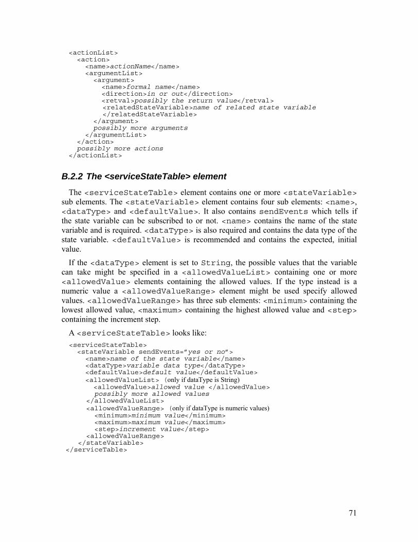
71
<actionList> <action> <name>actionName</name> <argumentList> <argument> <name>formal name</name> <direction>in or out</direction> <retval>possibly the return value</retval>
<relatedStateVariable>name of related state variable </relatedStateVariable> </argument> possibly more arguments </argumentList> </action> possibly more actions </actionList>
B.2.2 The <serviceStateTable> element
The <serviceStateTable> element contains one or more <stateVariable> sub elements. The <stateVariable> element contains four sub elements: <name>, <dataType> and <defaultValue>. It also contains sendEvents which tells if the state variable can be subscribed to or not. <name> contains the name of the state variable and is required. <dataType> is also required and contains the data type of the state variable. <defaultValue> is recommended and contains the expected, initial value.
If the <dataType> element is set to String, the possible values that the variable can take might be specified in a <allowedValueList> containing one or more <allowedValue> elements containing the allowed values. If the type instead is a numeric value a <allowedValueRange> element might be used specify allowed values. <allowedValueRange> has three sub elements: <minimum> containing the lowest allowed value, <maximum> containing the highest allowed value and <step> containing the increment step.
A <serviceStateTable> looks like: <serviceStateTable> <stateVariable sendEvents=”yes or no”> <name>name of the state variable</name> <dataType>variable data type</dataType> <defaultValue>default value</defaultValue> <allowedValueList> (only if dataType is String) <allowedValue>allowed value </allowedValue>
possibly more allowed values </allowedValueList> <allowedValueRange> (only if dataType is numeric values) <minimum>minimum value</minimum> <maximum>maximum value</maximum> <step>increment value</step> <allowedValueRange> </stateVariable> </serviceTable>

72
C GENA
General Event Notification Architecture (GENA) [4][20] is a protocol that enables devices to send HTTP notifications using multicast UDP. Multicast UDP is useful for sending a notification to several destinations using only one single request. GENA is used for eventing in UPnP.
Standard courier font is used to describe static information (i.e. Location) and italic courier is used to describe non static information (i.e. path to the device) in the GENA messages.
C.1 Subscription Subscription is used in UPnP when a control point wants to know when a state variable
has changed in a service. A subscription must have the following headers:
• Host which specifies the publisher’s domain name and port.
• NT which specifies what sort of notification the subscriber wants to be notified of. Must be upnp:event.
• Call-back which specifies how the subscriber is to be contacted with a notification.
It may also contain a timeout request header which specifies how long the subscription is valid for.
A typical subscription looks like: SUBSCRIBE publisher path HTTP/1.1 Host: publisher Host:Port Callback: deliveryURL NT: upnp:event Timeout: seconds the subscription is valid
C.1.1 Subscription response
A response to a subscription must contain the following headers:
• Server which contains operative system name and version, UPnP/1.0 and product version.
• Service Identification (SID) which contains a unique subscription identifier starting with uuid.
• Timeout which contains the time the subscription is valid in seconds. It may be set to infinity.
The event is recommended to contain a date header with the date when the response was generated. The answer also contains a return code which tells if the request was accepted or not and if not why it was rejected.
A typical subscription request looks like:

73
HTTP/1.1 return code OK Date: when the response was generated Server: OS/version UPnP/1.0 product/version SID: uuid:unique subscription identification Timeout: Second-time of subscribtion duration, might be infinity
C.1.2 Subscription renewal
A subscription must be renewed before the duration of the subscription has expired (not necessary if the timeout is set to infinity). A subscription renewal must contain the following headers:
• Host which specifies the publishers domain name and port
• SID which must be the same as in the response to the original subscription request
It is also recommended that the re-subscription contains the timeout header with the duration of the subscription renewal in seconds.
A typical subscription renewal looks like: SUBSCRIBE publisher path HTTP/1.1 Host: publisher host:port SID: uuid:same unique subscription id as the original Timeout: Second- time of subscribtion duration, might be infinity
C.2 Un-subscription Un-subscription is used when a control point no longer wants to receive updates
regarding the specific state variable. A un-subscription must contain the following headers:
• Host which specifies the publishers domain name and port
• SID which must contain the unique identifier of the subscription that is to be canceled.
A typical un-subscription looks like: UNSUBSCRIBE publisher path HTTP/1.1 Host: publisher host:port SID: uuid:the unique id of the subscription to cancel.
C.3 Notification Notification is used when a publisher wants to inform a subscriber that an event has
occurred. A notification must contain the following headers:
• Host which specifies the delivery URL.
• Content-Length which contains the length of the body in bytes.
• Content-Type which must be text/xml because body is formatted using XML.
• NT which specifies the notification type. Must be upnp:event.

74
• NTS which specifies the notification sub type. Must be upnp:propchange.
• SID which must contain the unique identifier of the subscription.
• SEQ which contains the event key. This must be 0 for the initial event and incremented by 1 for every new event. This is used by the subscriber to check that it has not missed any event.
A header for a notification message looks like: NOTIFY delivery path HTTP/1.1 Host: delivery host:path Content-Type: text/xml Content-Length: length of body in bytes NT: upnp:event NTS: upnp:propchange SID: uuid:unique id of subscription SEQ: event key
C.3.1 Notification message body
The body of a notification contains the information about the changed variables and is formatted using XML. The outermost element <propertyset> has its namespace set to urn:schemas-upnp-org:event-1-0. The <propertyset> element contains one or more sub elements of the type <property>. Each <property> element contains one or more sub element corresponding to the <name> sub element of the <stateVariable> element in the service description (see B.2.2). These sub elements contains the new values of the state variable.
A notify message body looks like: <e.propertyset xmlns:e=”urn:schemas-upnp-org:event-1-0”> <e:property> <name of state variable>new value</name of state variable> possibly more state variables <e:property> possibly more properties </e:propertyset>
75
D SOAP
Simple Object Access Protocol [3] [20] is a communication protocol that is used by UPnP control points to invoke actions on services. SOAP is not dependent on any underlying protocol. In UPnP HTTP is used as a transport protocol. XML is used to carry the actual message in a SOAP packet. SOAP contains of four main parts: SOAP message envelope, SOAP encoding rules, SOAP binding and SOAP RPC representation.
Standard courier font is used to describe static information (i.e. Location) and italic courier is used to describe non static information (i.e. path to the device) in the SOAP messages.
D.1 The SOAP message envelope The SOAP message envelope is the outermost container of SOAP messages. It comes
right after the transport protocol headers and is a well-formed XML message. The <Envelope> element has two children: <Header> which is optional and <Body> which is required.
D.1.1 The <Header> element
The <Header> element of the SOAP message envelope is optional and is used to carry supplementary information. There can be unlimited children nodes for the <Header> element.
D.1.2 The <Body> element
The <Body> element contains the essence of the message. This is where the method call, the method response or the error message for a failed call is stored. The <Body> element contains zero or more children.
D.2 The SOAP encoding rules The SOAP encoding rules define how to encode data types in a SOAP message. This
enables the use of different data types in the XML schema such as Boolean, 32-bit signed integer, date, string and more. It is not required to use SOAP encoding rules for encoding the data in a SOAP message.
D.3 The SOAP binding As mentioned before SOAP is not dependent on any particular underlying protocol.
However conventions must be established for a transport protocol to be able to carry SOAP’s XML payload. The request/response of SOAP matches the HTTP model. There are however other things that have to be agreed: how to set HTTP content type, additional HTTP headers to use and how errors are handled. A SOAP message is sent as an HTTP POST with the Content-type set to text/xml because the content is a XML document. The

76
Host field informs where the wanted device is located and Content-Length tells the length of the body.
To make sure that new headers are not confused with other HTTP extensions SOAP over HTTP uses the MAN header [31]. According to SOAP specifications a SOAP Request must first be attempted without the MAN header but if the request is answered with 405 Method Not Allowed there must be a second attempt using the MAN header.
D.3.1 The SOAP HTTP Request
A new HTTP header, SOAPAction is used for SOAP Requests. The value of the SOAPAction header is a URI that lets the receiver know the particular service it is meant for. The action invoked is sent in the body part of the SOAP envelope. A typical SOAP Request looks like: POST /Checkout HTTP/1.1 Host: controlURL host:port Content-Type: text/xml Content-Length: length of body in bytes SOAPAction: controlURL host:port/service <s:Envelope xmlns:s=’http://www.w3.org/2001/06 soap-envelope’> <s:Body>
Body of request here </s:Body> </s:Envelope>
D.3.2 The SOAP HTTP Response
The SOAP HTTP Response is contained in a standard HTTP message with the result of the invoked action in the body part of the SOAP envelope. The status codes of the SOAP Response follow the HTTP standard with 2xx as success (for complete status codes see [31]). If an error occurs an error code is returned and the SOAP fault will be in the body part of the SOAP envelope. A typical SOAP HTTP Response looks like: HTTP/1.1 control code control status Content-Type: text/xml Content-Length: length of body in bytes <s:Envelope xmlns:s=’http://wwww.w3.org/2001/06 soap-envelope’> <s:Body> Body of response here </s:Body> </s:Envelope>
D.4 The SOAP RPC representation The SOAP RPC representation is a convention for representing remote procedure calls
and responses. This is what decides what the body part of the SOAP HTTP request/response look like.

77
D.4.1 Action Request
An Action Request is used when a control point wants to invoke an action on a service. It uses a SOAPAction header with the value set to the service the action is to be invoked on. The body consists of a SOAP Envelope. The <Body> element of the SOAP Envelope contains information about the action request. It contains a required <actionName> element which contains the name of the wanted action in the service. If the action has one or more arguments they will be in a sub element called <argumentName>. A typical action request looks like: POST controlURL HTTP/1.1 Host: controlURL host:port Contene-Length: length of body in bytes Content-Type: text/xml SOAPAction:“urn:schemas-upnp-schemas-
org:service:serviceType:version#actionName” <s:Envelaope xmlns:s=”http://schemas.xmlsoap.org/soap/envelope/” s:encodingStyle=”http://schemas.xmlsoap.org/soap/encoding/”> <s:Body> <u:actionName xmlns:u=”urn:schemas-upnp-org:service: ServiceType:v”> <argumentName>in argument value</argumentName> </u:actionName> </s:Body> </s:Envelope>
D.4.2 Action response
According to the UPNP architecture a service has 30 seconds to complete an action request and answer it with an action response. This answer is a SOAP HTTP Response with the action response in <Body> of the SOAP Envelope. In <Header> there is a Date field that states when the response was generated and an Ext field that confirms that the MAN header was understood if one were used. A typical action response looks like: HTTP/1.1 response code response status Content-Length: length of body in bytes Content-Type: text/xml Date: when response was generated Ext: Server: OS/version UPnP/1.0 product/version <s:Envelope xml:s”http://schemas.xmlsoap.org/soap/envelope/” s:encodingStyle=”http://schemas.xmlsoap.org/soap/encoding/”> <Body> Information about the result of the action request </s:Body> </s:Envelope> The <Body> element and the response code and response status are dependent on
however the action request succeeded or not. If the request succeeded the response code and response status would typically be 200 OK and the <Body> element looks like:

78
<s:Body> <u:actionNameResponse xmlns:”urn:schemas-upnp-org:service: serviceType:version”> <argumentName>output argument value</argumentName> </u:actionNameResponse> </s:Body> If the request instead would fail the response code would be according to HTTP
standards [31] depending on the error. A typical response code and response status could be 500 Internal Server Error. The body of an error response must have a <Fault> element with sub elements <faultcode>, <faultstring> and <detail>. <faultcode> must contain Client and <faultstring> must contain UPnPError. The <detail> element contains a sub element <UPnPError> that itself has two sub elements <errorCode> and <errorDescription> containing information about the specific error that occurred. The <Body> element of the error response looks like: <s:Body> <s:Fault> <faultcode>soap:Client</faultcode> <faultstring>UPnPError</faultstring> <detail> <UPnPError xmlns=”urn:schemas-upnp-org:control-1-0”> <errorCode>error code</errorCode> <errorDescription>error string</errorDescription> </UPnPError> </detail> </s:Fault> </s:Body>

79
Bibliography [1] T. Fout, Universal Plug and Play in Windows XP,
http://www.microsoft.com/technet/prodtechnol/winxppro/evaluate/upnpxp.mspx, July 2001
[2] Y. Y. Goland, T. Cai, P. Leach and Y. Gu, Simple Service Discovery Protocol/1.0 Operating without an Arbiter, draft-cai-ssdp-v1-03.txt, IETF draft, October 1999
[3] D. Box, G. Kakivaya, A. Layman, S. Thatte and D. Winer, SOAP: Simple Object Access Protocol, draft-box-http-soap-01.txt, IETF draft, November 1999
[4] J. Cohen, S. Aggarwal and Y. Y. Goland, General Event Notification Architecture Base: Client to Arbiter, draft-cohen-gena-p-base-01.txt, IETF draft, September 2000
[5] UPnP Forum, http://www.upnp.org/, May 2005
[6] B. A. Miller, T. Nixon, C. Tai, M. D. Wood, Home Networking with Universal Plug and Play, IEEE Communications Magazine, pages 104-109, December 2001
[7] Jini Architectural Overview, http://www.sun.com/software/jini/whitepapers/architecture.html, January 1999
[8] S. Helal, Standards for Service Discovery and Delivery, IEEE Pervasive Computing, pages 95-100, July 2002
[9] Choonhwa Lee and Sumi Helal, Protocols for Service Discovery in Dynamic and Mobile Networks, International Journal of Computer Research, Volume 11, Number 1, pages 1-12, September 2000
[10] Microsoft Knowledge Base, UPnP devices must be powered up at all times, article ID 298653, http://support.microsoft.com/default.aspx?scid=kb;en-us;298653, May 2005
[11] R. Troll, Automatically Choosing an IP Address in an Ad-Hoc IPv4 Network, draft-ietf-dhc-ipv4-autoconfig, IETF draft, March 2000
[12] Jini Network Technology homepage, http://www.sun.com/software/jini/, May 2005
[13] The Salutation Consortium, http://www.salutation.org, May 2005
[14] Bluetooth SIG, Inc., https://www.bluetooth.org/, May 2005
[15] Plug And Play for Windows 2000, http://www.microsoft.com/technet/prodtechnol/ windows2000pro/evaluate/featfunc/plugplay.mspx, May 2005 [16] Microsoft Network Device Class, http://www.microsoft.com/whdc/resources/
respec/specs/pmref/PMnetwork.mspx, December 2001
[17] IEEE Standard 802.15.4-2003, Institute of Electrical and Electronics Engineers, Inc, October 2003
[18] C. Evans-Pughe: Bzzzz zzz -- ZigBee wireless standard, IEE Review, Volume 49 Number 3, pages 28 - 31, March 2003

80
[19] A. El-Hoiydi, J.-D. Decotignie and J Hernandez, Low Power MAC Protocols for Infrastructure Wireless Sensor Networks, Proc. European Wireless (EW'04), pages 563-569, February 2004
[20] M. Jeronimo and J. Weast, UPnP Design by Example, Volume 1, April 2003
[21] J. Klamra and M. Olsson, Power management in UPnP, http://www.csee.usf.edu/~christen/upnp/main.html, June 2005
[22] Magic Packet Technology, http://www.amd.com/us-en/assets/content_type/ white_papers_and_tech_docs/20213.pdf , November 1995
[23] Intel Software for UPnP Technology, http://www.intel.com/technology/upnp/, May 2005
[24] Ethereal, A Network Protocol Analyzer, www.ethereal.com, May 2005
[25] E. Shih, P. Bahl and M. J. Sinclair, Wake on Wireless: An Event Driven Energy Saving Strategy for Battery Operated Devices, MOBICOM 2002 pages 160-171, September 2002
[26] B. Nordman and A. Meier, Energy Consumption of Home Information Technology, Lawrence Berkeley National Laboratory, LBNL-53500, July 2004
[27] K. Christensen, B. Nordman and A. George, The Next Frontier for Communications Networks: Power Management, Computer Communications, Volume 27, Number 18, pages 1758-1770, December 2004
[28] Energy Star, http://www.energystar.gov/, May 2005
[29] L. Constantin, Network library, netwib, http://www.laurentconstantin.com/ en/netw/netwib, May 2005
[30] Dev C++, http://www.bloodshed.net/dev/devcpp.html, May 2005
[31] R. Fielding, J. Gettys, J. Mogul, H. Frystyk, L. Masinter, P. Leach, T. Berners-Lee, Hypertext Transfer Protocol -- HTTP/1.1, W3C standard, June 1999
[32] Dynamic Host Configuration Protocol, RFC 2131, IETF request for comments
[33] B. Nordman, Lawrence Berkeley National Laboratory, personal communication, May 2005
[34] Energy Analysis Program at Lawrence Berkeley National Laboratory, http://eetd.lbl.gov/EAP/, May 2005