design and evaluation of a new aerodynamic lens for the...
TRANSCRIPT
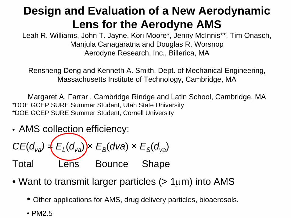
Design and Evaluation of a New Aerodynamic Lens for the Aerodyne AMS
Leah R. Williams, John T. Jayne, Kori Moore*, Jenny McInnis**, Tim Onasch, Manjula Canagaratna and Douglas R. Worsnop
Aerodyne Research, Inc., Billerica, MA
Rensheng Deng and Kenneth A. Smith, Dept. of Mechanical Engineering, Massachusetts Institute of Technology, Cambridge, MA
Margaret A. Farrar , Cambridge Rindge and Latin School, Cambridge, MA*DOE GCEP SURE Summer Student, Utah State University*DOE GCEP SURE Summer Student, Cornell University
• AMS collection efficiency:
CE(dva) = EL(dva) × EB(dva) × ES(dva)
Total Lens Bounce Shape
• Want to transmit larger particles (> 1µm) into AMS
• Other applications for AMS, drug delivery particles, bioaerosols.
• PM2.5

Experimental SetupSize Selection
Differential Mobility Analyzer(DMA)
Atomizer
Light Scattering (LS)
Vaporizer
InputCondensation Particle Counter
(CPC)Detection
Aerosol Mass Spectrometer(AMS)
Aerosol Source
Mass Detected = # DetectedMass Input # Input
Detection Ratio =

Standard LensOrifice assembly
Valve body Aerodynamic lens
a)
1.6mm ID
450mm
3.8mm
OD
7”, 178mm
6.055”, 154mm
FEDCBA100 µm orifice Flight
region
b
Lens system
1.2
1.0
0.8
0.6
0.4
0.2
0.0
Tran
smis
sion
Effi
cien
cy (E
L)
102 3 4 5 6 7 8 9
1002 3 4 5 6 7 8 9
10002
Dva (nm)
Experimental Data 585 torr 760 torr
CFD Model 585 torr 760 torr
• Need to model entire lens system, including critical orifice mounting assembly, valve and aerodynamic lens. Loss of particles on steps in plumbing.• Include Brownian motion in lens as well as in flight region.• Still some disagreement between CFD model and experimental measurements.• Transmission Efficiency of an Aerodynamic Focusing Lens System: Comparison of Model Calculations and Laboratory Measurements for the Aerodyne Aerosol Mass Spectrometer , Peter S. K. Liu, Rensheng Deng, Kenneth A. Smith, Leah R. Williams, John T. Jayne, Manjula R. Canagaratna, Kori Moore, Timothy B. Onasch, Douglas R. Worsnop, and Terry Deshler, submitted to AS&T 2006
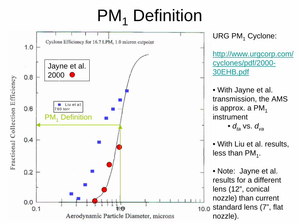
PM1 DefinitionURG PM1 Cyclone:
http://www.urgcorp.com/cyclones/pdf/2000-30EHB.pdf
• With Jayne et al. transmission, the AMS is approx. a PM1instrument
• dta vs. dva
• With Liu et al. results, less than PM1.
• Note: Jayne et al. results for a different lens (12”, conical nozzle) than current standard lens (7”, flat nozzle).
Jayne et al.2000
PM1 Definition
2 3 4 5 6 7 8 91000
2
Liu et a l.7 60 torr
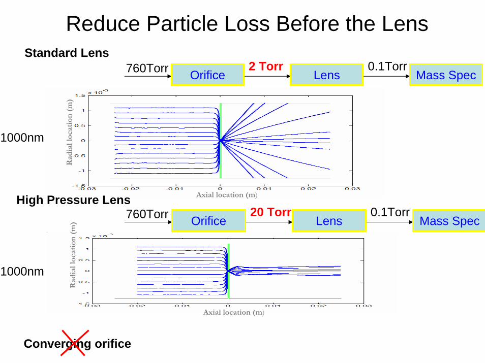
Reduce Particle Loss Before the LensStandard Lens
Orifice Lens Mass Spec760Torr 2 Torr 0.1Torr
Orifice Lens Mass Spec760Torr 20 Torr 0.1TorrAxial location (m)
Rad
ial l
ocat
ion
(m)
1000nm
Axial location (m)
Rad
ial l
ocat
ion
(m)
1000nm
High Pressure Lens
Converging orifice

High P Lens version 1Scale: Axial(1:1), Radial(1:2)
7”(177.8mm)
34.4mm20mm
19mm
0.2mm
16.5mm4.4mm 2.0mm 1.8mm 1.6mm 1.4mm 1.2mm 1.0mm 0.9mm
1.6mm
2mm
0.8mm
• Based on design published by Schreiner, et al. (1999) Aerosol Sci. Tech. 31: 373-382.• Optimized for constraints of AMS, e.g., lens length, pumping capacity, etc., with CFD calculations (FLUENT)• Small aperture sizes makes machining difficult. First attempts with traditional machining were abysmal failure. • Electrical discharge machining (EDM) worked well.

Orifice-lens assembly
-0.36 -0.30 -0.24 -0.18 -0.12 -0.06 0.00-0.015
-0.010
-0.005
0.000
0.005
0.010
0.015
Nozzle
Diameter of pinhole is 80/100/120 microns.Diameters of connection and lens tube are 4.4mm.Diameter of the nozzle is 1.0mm.
LensConnectionPinhole
Y (m
)
X (m)
Constant bore of 4.4 mm from orifice to lens entrance.“New Inlet”

Results for HP Lens v1
350
300
250
200
150
100
50
0
Parti
cle
Velo
city
(m/s
)
2 3 4 5 6 7 8 9100
2 3 4 5 6 7 8 91000
2 3 4
Daero (nm)
High P Lens, ARI2100 micron orifice
ari2_2_AN_vel ari2_2_AN_LS_vel ari2_2_PSL_vel ari2_2_Na_vel ari2_2_Na_LS_vel ari2_2_Pb_vel ari2_2_Pb_LS_vel
fit_ari2_2_all_velV_param_0 = 408.46 ± 13V_param_1 = 79.599 ± 2.06V_param_2 = 138.57 ± 10.2V_param_3 = 0.97034 ± 0.0369
HP_F_Vel, Deng's calc. vel
1.0
0.8
0.6
0.4
0.2
0.0
Tran
smis
sion
Effi
cien
cy
5 6 7 8 9100
2 3 4 5 6 7 8 91000
2 3 4
Daero (nm)
TE_results_AN_100 TE_results_Na_100 TE_results_Pb_100 Calc_TE_100
1.0 1.0
0.8 0.8
0.6 0.6
0.4 0.4
0.2 0.2
0.0 0.0
Tran
smis
sion
Effi
cien
cy
5 6 7 8 9100
2 3 4 5 6 7 8 91000
2 3 4 5 6
Daero (nm)
ARI2, HighPLens120 micron pinhole
TE_AN_3 TE_AN_LS_3 TE_Na_3 TE_Na_LS_3 TE_Pb_3 TE_Pb_LS_3 wave1, Deng calc.
10 100 1000 10000
0.0
0.2
0.4
0.6
0.8
1.0
10 100 1000 10000
Pinhole(um) 160 140 120 100 80 60
Tr
ansm
issi
on e
ffici
ency
Dp, nm
CFD results for different orifice diameters.
Good agreement between calculated and measured particle velocities.
Experimental results for 100 µm orifice.
Experimental results for 120 µm orifice. Undesirable!

High Pressure Lens v2
Scale: Axial(1:1), Radial(1:2)
7”(177.8mm)
34.4mm20mm
19mm
0.2mm
16.5mm4.95mm 2.25mm 2.024mm1.8mm 1.574mm1.35mm 1.124mm 1.012mm
1.8mm
2mm
0.9mm
All radial dimensions are scaled up from the previous lens by 12.5%, with all axial dimensions fixed.
• Larger apertures gives lower pressure at lens entrance and should shift transmission window to smaller sizes.• We did not scale up the bore of the orifice-valve assembly to 4.95 mm.

Calculated axis pressure
-0.35 -0.30 -0.25 -0.20 -0.15 -0.10 -0.05 0.00 0.050
150
300
450
600
750
900
Pres
sure
(Tor
r)
Axial location (m)
-0.30 -0.25 -0.20 -0.15 -0.10 -0.05 0.00 0.050
5
10
15
20
25
30
P=9.1Torr
P=19.0Torr
P=13.6Torr
120um 100um 80um
Pre
ssur
e (T
orr)
Axial location (m)

Calculated transmission efficiency
10 100 1000 100000.0
0.2
0.4
0.6
0.8
1.010 100 1000 10000
o80 o100 o120
Tran
smis
sion
Effi
cien
cy
dp (nm)
O120, Q=108.0sccm(or 118.8ccm at 300K)
Window: 0.115-4.35µm
O100, Q=74.1sccm(or 81.4ccm at 300K)
Window: 0.075-3.5µm
O80, Q=46.9sccm (or 51.5ccm at 300K)
Window: 0.047-1.85µm

Calculated and Measured Particle Velocity
300
250
200
150
100
50
0
Vel
ocity
(m/s
)
2 3 4 5 6 7 8 9100
2 3 4 5 6 7 8 91000
2 3
Dva (nm)
100um pinhole 120um pinhole fit_velocity_100 fit_velocity_120 V_calc_100 V_calc_120

High Pressure Lens: 100 µm Orifice
1.0
0.8
0.6
0.4
0.2
0.0
Det
ectio
n R
atio
2 3 4 5 6 7 8 9
1022 3 4 5 6 7 8 9
1032 3 4 5 6 7 8 9
104
Dva (nm)
High Pressure Lens100µm Orifice
MS NH4NO3 LScnts NH4NO3 LScnts NaNO3 Numerical Calculation
Standard Lens Standard Lens
•Much better transmission efficiency for larger particles (350nm-2µm)•Still not as good as calculated values

High Pressure Lens: 120 µm Orifice1.0
0.8
0.6
0.4
0.2
0.0
Det
ectio
n R
atio
2 3 4 5 6 7 8 9
1022 3 4 5 6 7 8 9
1032 3 4 5 6 7 8 9
104
Dva (nm)
High Pressure Lens120µm Orifice
MS NH4NO3 LScnts NH4NO3 LScnts NaNO3 Numerical Calculation
Standard Lens Standard Lens
• Narrower transmission efficiency than calculation predicts• Slightly better transmission for large particles than standard lens

High Pressure Lens: 70/80 µm Orifice1.0
0.8
0.6
0.4
0.2
0.0
Det
ectio
n R
atio
2 3 4 5 6 7 8 9
1022 3 4 5 6 7 8 9
1032 3 4 5 6 7 8 9
104
Dva (nm)
High Pressure Lens70 µm Orif ice
MScnts NH4NO3 LScnts NH4NO3 LScnts NaNO3 CFD Calculation, 80 µm Standard Lens
• Narrower transmission efficiency than calculation predicts

Calculated particle trajectories
2 µm2µm Particles (scale Y:X =10:1)
1 µm
1µm Particles (scale Y:X =10:1)
0.5µm Particles (scale Y:X =10:1)
0.5 µm
See deposition of material on back of critical orifice. Particles caught in eddies impacting?
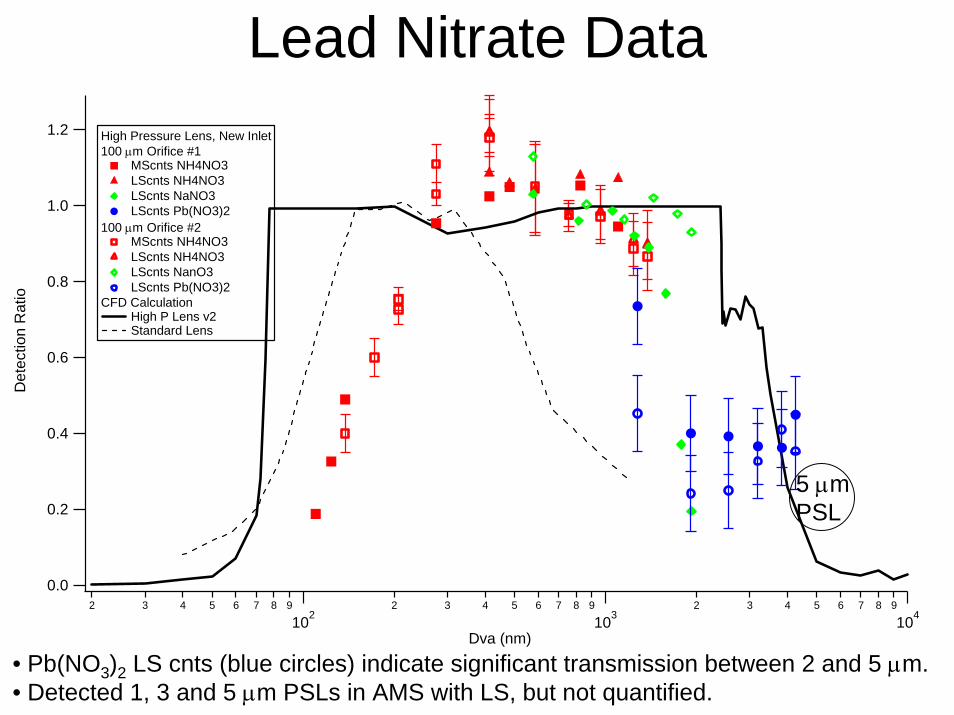
Lead Nitrate Data1.2
1.0
0.8
0.6
0.4
0.2
0.0
Det
ectio
n R
atio
2 3 4 5 6 7 8 9
1022 3 4 5 6 7 8 9
1032 3 4 5 6 7 8 9
104
Dva (nm)
High Pressure Lens, New Inlet100 µm Orifice #1
MScnts NH4NO3 LScnts NH4NO3 LScnts NaNO3 LScnts Pb(NO3)2
100 µm Orifice #2 MScnts NH4NO3 LScnts NH4NO3 LScnts NanO3 LScnts Pb(NO3)2
CFD Calculation High P Lens v2 Standard Lens
• Pb(NO3)2 LS cnts (blue circles) indicate significant transmission between 2 and 5 µm.• Detected 1, 3 and 5 µm PSLs in AMS with LS, but not quantified.
5 µm PSL

High Pressure Lens: New Inlet vs Standard Inlet
• New inlet better then standard inlet for large particle sizes.• Standard valve on high pressure lens looks very similar to standard
valve on standard lens.• Confirms calculation result that particles lost in orifice/valve plumbing.
1.0
0.8
0.6
0.4
0.2
0.0
Det
ectio
n R
atio
2 3 4 5 6 7 8 9
1022 3 4 5 6 7 8 9
1032 3 4 5 6 7 8 9
104
Dva (nm)
High Pressure Lens100µm orificeConstant Bore Valve
MS NH4NO3 LScnts NH4NO3
LScnts NaNO3 Numerical Calculation
Standard Valve MScnts NH4NO3 LScnts NH4NO3 Standard Lens

Standard Lens: New Inlet vs Standard Inlet
1.0
0.8
0.6
0.4
0.2
0.0
Det
ectio
n R
atio
4 5 6 7 8 9100
2 3 4 5 6 7 8 91000
Dva (nm)
Standard Lens100µm OrificeConstant Bore Valve
MS NH4NO3 LScnts NH4NO3 LScnts NaNO3
Standard Valve MS NH4NO3 LScnts NH4NO3 LScnts NaNO3 Standard Lens
•Inlet does not have a large effect on standard lens system.

Pressure Controlled Inlet• 0.25 mm aperture, tee to pump, 150 µm orifice, tee to pressure gauge.
• Vary pressure at lens entrance from 12 torr to 23 torr.
Pump
0.25 mm 150 µm
100 torrBaratron
Valve HPL v2
Needle Valve
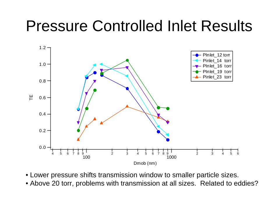
Pressure Controlled Inlet Results1.2
1.0
0.8
0.6
0.4
0.2
0.0
TE
4 5 6 7 8 9100
2 3 4 5 6 7 8 91000
2 3 4 5 6
Dmob (nm)
PInlet_12 torr Pinlet_14 torr PInlet_16 torr PInlet_19 torr Pinlet_23 torr
• Lower pressure shifts transmission window to smaller particle sizes.• Above 20 torr, problems with transmission at all sizes. Related to eddies?

1.2
1.0
0.8
0.6
0.4
0.2
0.0
TE
4 5 6 7 8 9100
2 3 4 5 6 7 8 91000
2 3 4 5 6
Dmob (nm)
Pinlet_14 torr TE_100 HPL v2
1.2
1.0
0.8
0.6
0.4
0.2
0.0
TE4 5 6 7 8 9
1002 3 4 5 6 7 8 9
10002 3 4 5 6
Dmob (nm)
PInlet_19 torr TE_120 HPL v2
Pressure Controlled Inlet Results
• Comparison of pressure controlled inlet with HPL v2 at same pressures as 100 µm orifice and 120 µm orifice. • At 14 torr, extra plumbing removes larger particles. At 19 torr, extra plumbing doesn’t make much difference.

Conclusions
• Better transmission of 600 nm to 2 µm particles, but still a work in progress.
• Smooth bore inlet helps with high P lens, but not with standard lens.
• Some things not captured by calculations, e.g., deposition on back of orifice.