design and development of windmill operated water pump · pdf fileshubham choukade, be...
TRANSCRIPT
International Journal of Engineering and Technical Research (IJETR)
ISSN: 2321-0869 (O) 2454-4698 (P), Volume-3, Issue-12, December 2015
61 www.erpublication.org
Abstract— The imminent exhaustion of fossil energy
sources,spreading global warming,expanding greenhouse effect
, higher need of energy , less availability of power supplies
motivates us to use renewable source of energy like wind-energy
which is most prominent for our suitable application.Small wind
turbines need to be cost effective, loyal, affordable minimum
maintenance cost for any average person . It produces costlier
electricity than medium and large scaled wind mills, specially in
areas where availability of wind sites are less and in
self-governing applications. However, after perfectly sized and
used at optimal working climate, small-scale wind mills could be
a dependable energy source and produce socio-economically
valuable energy not only in developing countries but also in local
applications . The small-scaled wind mills have different
aerodynamic behaviour than their large-scale wind mills. Poor
performance of small wind mills is due to laminar separation
and in turns on the rotor blades because of low Reynolds
number (Re) resulting from low wind speeds and small rotor
capacity . Low Reynolds number airfoils permits starting at
lower wind velocity , increasing the starting torque and thus
improving the overall performance of the turbine .Designing of
rotor of windmill will includes optimizing the rotor and its
components to achieve maximum power coefficient and
efficiency . The pitch twist and allotment of chord length are
optimized based on conservation of angular momentum and
theory of aerodynamic forces on an airfoil. Blade Element
Momentum (BEM) theory is first derived then used to conduct a
parametric study that will determine if the optimized values of
blade pitch and chord length create the most efficient blade
geometry.
Index Terms—About Wind energy, wind mill, rotor, blade
design, power coefficient four key words or phrases in
alphabetical order, separated by commas.
I. INTRODUCTION
Water pumping is very important , most basic wide-spread
energy needs in rural areas of the world. It has been found that
more than half the world's rural population does not have
approach to clean water supply [1]. Water supplies like wells,
dugouts , rivers can often used for agricultural fields.
However, due to limited availability of power supplies or
resources some alternate form of energy has to be used to
supply water from the source to a point of consumption. Wind
energy is an important source of renewable energy that can be
used for pumping water in remote locations. A wind pump is
nothing but a windmill used for pumping water, either as a
Ronak Dipakkumar Gandhi, BE Mechanical , MIT Academy of
Engineering , Pune University , Pune , Maharashtra , India
Pramod Kothmire, Ph.D. IIT Bombay (pursuing), Assistant Professor,
MIT Academy of Engineering, Pune University , Pune , Maharashtra , India.
Debarshi Sharma, BE Mechanical , MIT Academy of Engineering ,
Pune University , Pune , Maharashtra , India
Bhushan Kumbhare, BE Mechanical , MIT Academy of Engineering ,
Pune University , Pune , Maharashtra , India
Shubham Choukade, BE Mechanical , MIT Academy of Engineering ,
Pune University , Pune , Maharashtra , India
source of fresh water or wells. It is one of the earliest methods
of utilizing the energy of the wind to pump water.
Popular renewable energy sources making an expandable
contribution to the energy supplies in view of encouraging
renewable energy sources endowments, limitations and
unpredictably supply of fossil fuel , and rise in pressure in
environment due to generation of conventional energy.
Among the renewable energy resources, the generation of
electrical energy & mechanical energy by wind mills has
emerged as a feasible and cost-effective option.
With the rise in understanding of global warming due to
Carbon Dioxide produced by burning of fuels, the use of
natural energy resource is coming into picture. Now a day
people are started using of natural sources like wind, hydro ,
solar energy to produce electricity and providing power to the
various power-plants. The use of wind mills is one of the most
popular methods of using the energy from natural sources.
Windmills were used in earlier days to run the pump &
pumping the water from the well. Wind mills are not used
because they mostly depend on the wind blowing . however, a
small scale wind mills can be used to power small home
appliances by decreasing the electricity cost and quantity of
fuel burnt to produce equal amount of electricity.
Wind mills utilize energy from the wind to produce
electricity. A typical system in an disclosed site could easily
genrate more power than household lamps and other use of
electrical appliances [3] . Just like any engineering design
posses challenges, household wind turbine also posses
various challenges such as noise, aesthetics, purchasing cost,
repair cost etc.
This research paper explain idea about the current designs of
the small scale wind mills along with the market requirement
followed by the design of an innovative wind mills system. In
this research paper focussed areas such as current designs,
power generation, blade design power saving and fail safe
methods are taken into consideration. The paper also
considers the development difficulty limiting the design
enhancement such as noise, aesthetics, material cost,
maintenance, and other issues. These are the problems which
may affect the design, manufacturing and marketing of the
product. This report also elaborates the design and
development of such a wind turbine blade profile for domestic
application by comparison with various profiles. This
research is used for producing electricity at low wind speeds
which can be used to power the lighting requirements of a
house.
Design and Development of Windmill Operated
Water Pump
Ronak D Gandhi, Pramod kothmire, Debarshi Sharma, Bhushan kumbhare, Shubham Choukade

Design and Development of Windmill Operated Water Pump
62 www.erpublication.org
Figure No 1: Sources Of Energy
A. Objectives-
To built up small scale wind turbine & to see (study)
feasibility of it.
To Reduce weight and cost .
To design & develop water pump which will cope up
with ordinary pump.
B. Need-
Growing awareness of rising levels of greenhouse
gases
Global warming
Increasing prices of fossil fuels
Limited power supplies .
Increasing dependency on renewable energy than
non renewable source of energy.
Figure No 2: Renewable Energy
C. Scope Of Project
• Cascading of Solar and Wind energy for running specific
application like waterpump etc.
• Wind energy can be used for electricity or power
generation.
• Efficiency or power output of pump can be improved by
optimizing blade parameters such as blade thickness ,blade
length , blade profile , number of blades etc.
D. Methodology
Analytical study
• Research Papers
• Formulas
• Empirical Relations
Design of small wind turbine blades
• Blade angle
• Blade height
• Blade thickness
• Blade length
Experimentation with small wind turbines .
Measure velocity , power , discharge , torque , head etc.
Use the energy produced from small wind turbines for
suitable application like pumping water etc.
E. Concept Of The Project
Figure No 3: Concept of project [3]
II. LITERATURE REVIEW
A. Blade design and performance testing of a small wind
turbine rotor for low wind speed applications
Author Name: Ronit K. Singh, M. Rafiuddin Ahmed
Journal Name: Science Direct
Results : Turbine performing best at 18 degree pitch
angle. Peak power coefficient attained by the 2-bladed rotor
design at 6 m/s wind speed was 0.29.
B. Optimized Design of Rotor Blade for a Wind Pump
Author Name: Prasad S.S., Virupaxi Auradi
Journal Name: International Journal of Renewable
Energy Research
Results : P = ½ ρAV3 , Pout = 0.5 Cp ρAV
3 Watts , Pin
= 0.5 ηt Cp ρ AV3 Watts ,
P =Phyd / ηp , λr = λd r / R . Increasing the
chord width or the number of
blades may not necessarily result in higher
CP on the other hand; a good combination of the blade
parameters with lower chord width and fewer numbers of
blades can result in higher CP. In the present case, a blade

International Journal of Engineering and Technical Research (IJETR)
ISSN: 2321-0869 (O) 2454-4698 (P), Volume-3, Issue-12, December 2015
63 www.erpublication.org
with 30mm chord at the tip and 500 mm chord at the root
with 4 blades. and with twist varying from 8 degree at the tip
to 32 degree at the root gives a CP of 0.43, which is the best
for the rated wind speed and the diameter of the rotor.
C. Renewable energy source water pumping systems—A
literature review
Author Name: C. Gopal Mohanraj , Chandramohan ,
Chandrasekar
Journal Name: Science Direct
Results : For VAWT As=Dt*lb , Solidity =
Nc/Rrotor , Φ = 2/3 arc tan (1/λr) ,
σ = (B x C)/(2πr) , Φ = α + β .
D. Energy for water pumping in rural areas in sudan
Author Name: Abdeen Mustafa Omer
Journal Name: International Journal of Engineering
and Technology
Results : Mean wind speeds of 4 ms-1 are available
over 50% of Sudan, which suited for water lifting and
intermittent power requirements, while there is one region in
the eastern part of Sudan that has a wind speed of 6 ms-1,
which is suitable for power production. The data presented in
this paper can be considered as a nucleus of information for
research and development of wind energy project; however,
detailed investigation should determine the best specific sites.
Local manufacturer, whenever possible, it is recommended
for wind pump systems. Low cost designs as well as reliable
devices have to be provided. power density: Pa/A = 0.5 ρ V3 P
= 0.3409 V3 .
E. Design of a low Reynolds number airfoil for small
horizontal axis wind turbines
Author Name: Ronit K. Singha, M. Rafiuddin
Ahmeda,Mohammad Asid Zullahb, Young-Ho Leeb
Journal Name: Science direct
Results : The airfoil showed good lift
characteristics at low Reynolds numbers and at an angle of
attack as high as 14. The flat-back trailing edge of the AF300
airfoil has improved aero-dynamic properties by increasing
CL and the adding strength to the airfoil structure. structural
strength added by the thick trailing edge of the airfoil would
require lighter and less expensive materials for the blades
,decreasing the inertia and improving start-up and letting the
rotors operate at lower cut-in wind speeds.
III. TYPES OF WIND TURBINES
There are two types of wind turbines. One is Vertical axis
wind turbines and the other is horizontal axis wind turbines.
We also know that there is sufficient wind to satisfy much of
humanity’s energy requirements – if it could be gathered
effectively and on a large scale.
a. Vertical Axis Wind Turbines (VAWT) :- Vertical axis wind
turbines (VAWTs) which may be powerful, practically
simpler and significantly cheaper to build and maintain than
horizontal axis wind turbines (HAWTs). They have
advantages, such as they are always facing the wind, which
might make them a important for cheaper, cleaner renewable
resources of electricity. VAWTs might even be critical in
problems like currently facing electricity producers and
suppliers. Moreover, cheaper VAWT’s which may provide an
alternative to destruction of the rain forest for the growing
of bio-fuel crops.
Vertical axis wind turbines (VAWTs) in addition to being
simpler and cheaper to build, it has the following advantages:
They are always facing the wind hence no need to escort for
the wind.
Have greater surface area for energy storage hence can
store more energy.
Are more efficient in stormy or breezy winds.
Can be installed in locations like on roofs, along highways,
in parking lots.
Can be scaled more easily from milliwatts to megawatts.
Can be significantly less expensive to produce as they are
inherently simpler .
Can have low maintenance downtime as mechanisms are at
or near ground level.
Produce less noise due to low speed hence less noise.
Figure No 4 : Vertical axis wind turbine [5]
b. Horizontal Axis Wind Turbines(HAWT) : Horizontal-axis
wind turbines (HAWT) has the rotor main shaft and electrical
generator at the top of a tower, and may be pointed into or out
of the wind. Small turbines are pointed by a simple wind vane,
while large turbines generally use a wind sensor coupled with
a servo motor. Most have a gearbox, which turns the slow
rotation of the blades into a quicker rotation that is more
suitable to drive an electrical generator.
Some advantages of HAWT are –
• Variable blade pitch which gives the blades of turbines the
optimum attack angle. Allowing the attack angle to be
adjusted gives greater control, so that turbine can stores the
maximum amount of wind energy for the day and season time
.
• High efficiency, since the turbine blades always move
perpendicularly to the wind, collecting power through the
whole rotation. All vertical axis wind turbines, and most
airborne wind turbine designs, include various types of
reciprocating actions, requiring surfaces of the airfoil to
backtrack against the wind for part of the cycle. Backtracking
against the wind give rise to inherently lower efficiency.
• The taller tower base provides access to stronger wind in
sites with wind shear. In some wind shear sites, every ten
meters up, the speed of the winds can increase by 20% and the
output power by 34%.

Design and Development of Windmill Operated Water Pump
64 www.erpublication.org
Figure No 5: Horizontal axis wind turbine [5]
A. Characteristics & Specifications Of Windturbines:-
a) Wind Speed:-
This is very important to the productivity of a windmill. The
wind turbine only produces power with the wind. The wind
rotates the horizontal or vertical axis and causes the
generator shaft to sweep past the magnetic an electric current.
b ) Blade Length:-
This is important as the blade length is proportional to the
swept area. Larger blades have a greater swept area and thus
catch more wind. Because of this, they may also have more
torque.
c ) Base Height:-
The height of the base affects the windmill immensely. If the
windmill is higher, it will become more productive as the
altitude increases due to which increase in winds speed.
d ) Base Design:-
Some base design may be more stronger than others. Base is
most important during the construction of the windmill
because not only they support the windmill, but also they are
subjected to their own weight and the drag of the wind. If a
tower having weak base is subjected to these elements, then it
will definitely collapse. Therefore, the base must be identical
to ensure a fair comparison.
B. Requirements For Placing:-
a. Site Selection considerations:-
The power available in the wind increases rapidly with the
speed; hence wind energy conversion machines should be
placed in areas where the winds are strong & endless. The
following point have to be understand while selecting site for
Wind Energy Conversion System (WECS).
b. High annual average wind speed:-
The wind velocity is the most important parameter. The
power in the wind Pw, through a given X – section area for a
uniform Velocity of wind is given as :
Pw
= KV3
(K is constant)
It is important, because of the cubic dependence on velocity
of wind. small increases in V affect the power in the wind
E.g. doubling V, increases Pw
by a factor of 8.
c. Availability of wind V(t)
curve at the proposed site:-
This availability of wind curve help us to determine the
maximum energy in the wind and hence it is desirable to have
average speed of wind V such that
V ≥ 12-16km/hr i.e. (3.5 – 4.5 m/sec).
d. Wind structures at the proposed site:-
Wind notably near the ground is turbulent and gusty, &
changes rapidly in direction and in velocity. This separation
from homogeneous flow is called as “the structure of the
wind”.
e. Altitude of the proposed site:-
It affects the air density and thus the power in the wind &
hence a useful WECS electric power o/p. The wind tends to
have higher velocities at higher altitudes.
f. Local Ecology:-
If the surface is naked rock it may mean lower hub heights
hence lower cost of structure, if trees or grass or venations are
present. All of these tends to destructure the wind.
g. Nearness of site to local center/users:-
This criterion decreases length of transmission line, hence
losses & costs.
h. Nature of ground:-
Ground condition should be such that the foundations for
WECs are secured, surface of ground should be stable.
IV. DESIGN PROCEDURE
Steps in designing rotor of small wind turbines are as follows:
Figure No 6 : Design procedure of small wind turbines [8]
A. Sizing of Rotor
The power of the wind is proportional to air density, area of
the segment of wind being considered, the natural wind speed.

International Journal of Engineering and Technical Research (IJETR)
ISSN: 2321-0869 (O) 2454-4698 (P), Volume-3, Issue-12, December 2015
65 www.erpublication.org
The relationships between all the above variables are given in
equation [1]
Pw = ½ ρAu3………...[1]
Where,
Pw: power of the wind (W)
M: air density (kg/m3)
A: area of a segment of the wind being considered (m2)
u: undisturbed wind speed (m/s)
At standard pressure and temperature (STP = 273K and
101.3 KPa),equation [1] reduces to:
Pw =0.647ρAu3………….[2]
A turbine cannot extract or take 100% of the winds energy
because some of the winds energy used in pressure changes
occurring across the blades of turbines. This pressure change
causes velocity to decrease and therefore usable energy.
The mechanical power which could be obtained
from the wind with an ideal turbine is given as:
Pm = ½ M(16/27 Au3) ……………… [3]
Where,
Pm: mechanical power (W)
A: swept area of a turbine
16/27 : Betz coefficient
The Betz coefficient give idea that 59.3% of the power in the
wind can be obtained in the case of an ideal turbine.
For a VAWT, This area depends on both the
diameter and blade length of turbine .
swept area is: As = Dt lb …………………. [4]
Where,
As: swept area (m2)
Dt: diameter of the turbine (m)
lb: length of the turbine Blades (m)
Efficiency of turbines lies in the range of 35-40% is
very good, and occurs only in case for large-scale turbines. It
is important to note that the pressure drop across the turbine
blades is very small, around 0.02% of the ambient air
pressure.
so , Equation [3] can be re-written as Pm = CpPw
………………..[5]
The coefficient of performance depends on speed of wind,
rotational speed of the turbine and blade parameters such as
pitch angle and angle of attack.
a) Aerodynamic Design of Blade: Calculation of
Blade Setting Angle
Let us consider that the blade is divided into 8 equal
segments or elements. Now, consider in a unit element the
local tip speed ratio is given by: : λr = λd r / R
where,
r = radius of each element from the center of the
rotor.
c = chords at radius r.
Φ = local angle between relative wind direction
and rotor plane.
R = radius of the rotor
And local angle between relative direction of
wind and plane of rotor is given as :
Φ = 2/3 arc tan (1/λr)
The local solidity, σ is given by σ = (B x C)/(2πr)
where,
B = number of blades
C = Chords at radius r
We also know that Φ = α + β
where,
β= blade setting angle
α = angle of attack
Figure No 7: Aerodynamic design of blade [2]
b) Optimization Of Blade Parameters & Linearization
Of Blade Setting Angle
• For a given rotor diameter, most optimized values for blade
parameters is obtained for maximum power coefficient. The
blade parameters that has to be optimized are chord, quantity
of blades and setting angles of blades . A computer program
like Turbo C is used for finding out the CP for different blade
parameters.
• The values of β varies from root to blade tip and is not
linear. Fabrication such a blade with varying twist at each
element is difficult and expensive. Hence, as per standard
codes we have to keep the value of α between 2 - 8o.
Figure No 8: Optimization of blade parameters [6]

Design and Development of Windmill Operated Water Pump
66 www.erpublication.org
c) Airfoil & Its Behaviour
• An airfoil-shaped body displaced through a fluid generates
an aerodynamic force. The first component of this force in
direction perpendicular to motion is called lift. The second
component of this force in direction parallel to the motion is
called drag.
• Subsonic flight shaped airfoils have a shape with a rounded
leading edge, followed by a sharp trailing edge, often with
asymmetric camber. The lift on an airfoil blades is primarily
due to the result of its angle of attack and shape.
• When blades are oriented at a suitable angle, the airfoil
shaped blades deflects the on-coming air, resulting in a force
on the airfoil in the direction opposite to the deflection. This
resultant force is known as aerodynamic force and can be
resolved into two components: Lift and drag.
• Most airfoil shapes blades require a positive angle of attack
to produces lift, but cambered airfoils can generate lift at zero
attack angle .
Lift and drag forces experienced by turbines blades is shown
in figure below:
Figure No 9: Subsonic flight type airfoils [6]
d) Airofoil Behaviour
• Before studying the airfoil-behaviour, Mach number and
Reynolds number need to be studied. Mach number is nothing
but a ratio of speed of an object over sound and it is defined
as: 𝑀𝑎= 𝑣𝑠/𝑢𝑐 • Where 𝑀𝑎 is Mach Number , 𝑣𝑠 is object speed, 𝑢𝑐 is sound
speed. Subsonic is explained as Mach ≤ 1, transonic is
characterized as Mach = 1, supersonic is designated as Mach
≥ 1, and hypersonic is defined as Mach ≥ 5.
Figure No 10: Different flow in airfoil [15]
Black = laminar flow, red = turbulent flow, grey =
subsonic stream, blue = supersonic flow volume.
The Reynolds number is a non-dimensional value
and it is a ratio of inertial force to viscous force, designated as:
𝑅𝑒= 𝜌𝑉𝐿/ 𝜇
Airfoil behaviour can be described into three flow
regimes: the attached flow regime, the high lift/stall
development regime and the flat plate/fully stalled
regime.
In attached flow regime, flow is considered at the
upper surface of airfoil, in this situation, lift increases with the
angle of attack.
In high lift/stall development regime, the lift
coefficient peaks as the airfoil becomes increasingly stalled.
Stall occurs when the angle of attack exceeds a
certain value (depending on the Reynolds number) and
separation of the boundary layer on the upper surface takes
place.
It is essential to study the airfoil behaviour:
aerodynamic performances are different because of different
geometry of airfoil, and according to different airfoil’s
behaviour, choosing an applicable airfoil for wind turbine
blade will improve the efficiency.
The design of the turbines rotors is perhaps the most
important step of the entire turbine design. The rotors use
aerodynamic lift to provide a turning moment and
consequently an input torque to the gearbox.
There are many different standardized airfoil
profiles varying in cross-sectional profile and can be most
recognizably characterized by their camber, thickness and
chord length.
The design of the blades used in this project will be
based upon blade element theory and the Betz equation
V. MATERIAL CONSIDERATION FOR WINDMILL
The efficiency of a wind mill changes thus for good output it
is important to check material and its property for different
material the property are shows in fig(Table).

International Journal of Engineering and Technical Research (IJETR)
ISSN: 2321-0869 (O) 2454-4698 (P), Volume-3, Issue-12, December 2015
67 www.erpublication.org
Property Aluminum Extrusions Molded Plastic Wood Vinyl (Polyvinyl
Chloride)
Strength
(Tensile)
Very good mechanical
properties.
Wide variation in
properties from 0.08 to 8
tensile strength of
aluminum extrusions for
glass filled compounds.
Good
compressive
properties,
variable with the
species of wood
and moisture
content.
Low mechanical
properties.
Density Lightweight about 1/3 that of
copper or steel.
Very lightweight about
60% the weight of
aluminum.
Very
lightweight
about 1/3 the
density of
aluminum.
Very lightweight
about 60% the
density of
aluminum.
Strength Very Good. good. good. good.
Formability
Easily formable and
extruded in a wide variety of
complex shapes including
multi-void hollows.
Easily formed or molded
into complex shapes.
Poor; cannot be
routinely
formed.
Easily formed or
molded into
complex shapes.
Electrical
Conductivity
Excellent; twice as efficient
as copper, used in bus bar
and electric connector
applications.
Poor; used as an
insulator, high dielectric
capability.
Poor; cannot be
used as an
electrical
conductor
Usually cannot
be employed as
an insulator.
Poor; electrical
and thermal
insulating
characteristics.
Thermal
Conductivity
Excellent; ideal for heat
exchanger applications.
Poor; low coefficient of
thermal (heat) transfer. Poor. Poor.
Finishing
A finishes can be applied
including mechanical and
chemical prefinishes, anodic
coatings, paints and
electroplated finishes.
Color can be integral
with material as well as
plated, painted, and hot
stamped.
Paint and stain
coatings can be
employed.
Color can be
integral with
material.
VI. CONSTRUCTION DETAILS:-
A. vertical axis wind turbine:-
Vertical-axis wind turbines (or VAWTs) have the main rotor
shaft arranged vertically. Important advantages of this
arrangement is that the turbine does not need to be pointed
into the wind to be effective. This is an advantage on sites
where the wind direction is highly variable, for example when
integrated into buildings. The key disadvantages include the
low rotational speed with the consequential higher torque and
hence higher cost of the drive train, the inherently lower
power coefficient, the 360 degree rotation of the aerofoil
within the wind flow during each cycle and hence the highly
dynamic loading on the blade, the pulsating torque generated
by some rotor designs on the drive train, and the difficulty of
modeling the wind flow accurately and hence the challenges
of analyzing and designing the rotor prior to fabricating a
prototype.
Figure No 11: Vertical axis wind turbines

Design and Development of Windmill Operated Water Pump
68 www.erpublication.org
B. Slidercrank Mechanism:-
Arrangement of mechanical parts designed to convert
straight-line motion to rotary motion, as in a reciprocating
piston engine, or to convert rotary motion to straight-line
motion, as in a reciprocating piston pump. The basic nature of
the mechanism and the relative motion of the parts can best be
described with the aid of the accompanying figure, in which
the moving parts are lightly shaded. The darkly shaded part 1,
the fixed frame or block of the pump or engine, contains a
cylinder, depicted in cross section by its walls DE and FG, in
which the piston, part 4, slides back and forth. The small
circle at A represents the main crankshaft bearing, which is
also in part 1. The crankshaft, part 2, is shown as a straight
member extending from the main bearing at A to the crankpin
bearing at B, which connects it to the connecting rod, part 3.
The connecting rod is shown as a straight member extending
from the crankpin bearing at B to the wristpin bearing at C,
which connects it to the piston, part 4, which is shown as a
rectangle. The three bearings shown as circles at A, B, and C
permit the connected members to rotate freely with respect to
one another. The path of B is a circle of radius AB; when B is
at point h the piston will be in position H, and when B is at
point j the piston will be in position J. On a gasoline engine,
the head end of the cylinder (where the explosion of the
gasoline-air mixture takes place) is at EG; the pressure
produced by the explosion will push the piston from position
H to position J; return motion from J to H will require the
rotational energy of a flywheel attached to the crankshaft and
rotating about a bearing collinear with bearing A. On a
reciprocating piston pump the crankshaft would be driven by
a motor.
Figure No 12: Slider crank mechanism
C. TYPES OF PUMPS:-
a. Pump:-
Water is The Most Common Fluid handled by pump.
Virtually therefore all types of pumps may be considered as
potentially suitable for water lifting. However, pumps used
wind-powered pumping systems are generally found to be of
three types reciprocating ,rotary, displacement type. A
positive displacement type pump is that is which a measured
quantity of water is entrapped in a space its pressure is raised
and then it is delivered.
b. Reciprocating Pumps:-
In order to start reciprocating pump is reasonably low wind
speed. It is necessary to obtain sufficient starting torque which
is possible by using high rotor solidity. Hence many
windmills have a large number of vanes or sails to providing
high starting torque. All types of reciprocating pumps are
self-priming in that they do not need to be filled with fluid
before pumping. The fig shows pump cylinder. Its diameter
and length of plunger inside the pump is a major factor
indeterminate the windmill pumping capacity.
The Stroke of wind mill is a distance which the plunger moves
up and down. A short stroke enables the mill to begin
pumping in a light breeze but in strong breeze a long stroke
causes more water to be pumped. The fig shows the pump is
used commercial water pumping windmill.
c. Piston Pumps:-
A Piston type of pumps is normally used for deep wells, the
pumps being located the bore pipe directly underneath the
wind-mill and below the water level. Positive Displacement
type piston pumps are used to pump water from river and
lakes commonly used in conjunction with types of rotors, for
pumping from open or tube-wells.
Hand Pump is a main part in wind mill operated water pump.
This is a small scale water pump. This Pump Is connected to
the Slider Plate in a Other side of a slider crank Mechanism
.In Hand Pump One Side is connected To the Suction Port and
Other Side Is Connected to the delivery or outlet port.
d. Single-Acting Piston Pump:-
This consists of a cylinder with an inlet pipe and valves at the
base, a leather sealed piston with a one way valve and water
outlet at the top. Water passes through the pumps only on the
lifting stroke of the piston. These types of pumps are suitable
for medium or high heads with an operating speed of up to 40
strokes per minute. This type of pump has been used in
wind-mill.
The Pump Lift Water By:-
Direct lift:-
Many of the direct lift methods of lifting water require open
access to the water surface, i.e. buckets or containers on ropes
or a lever for mechanical advantage supported on a frame.
Persian type wheels rotate scoops or buckets in to the water,
which transfer the water on the down side of the rotation.
These can be employed in small-scale irrigation and to fill
cattle troughs. The construction of these is simple and basic
requiring a very low skill level.
Displacement pumps:-
Lift and suction pumps fall in to the category of displacement
pumps. These rely on a piston, which is close fitting within a
cylinder containing water. Lift pumps physically lift the water
that is above the piston up the pipe to the outlet. Suction
pumps have the piston above the surface of the water. By
lifting the piston a vacuum is created which displaces the
water up the pipe. A one way foot valve is needed to stop the
water in the pipe from flowing back in to the well/tank. Figure
2 shows the basic principles of lift, suction and displacement
pumps.
Suction pumps:-

International Journal of Engineering and Technical Research (IJETR)
ISSN: 2321-0869 (O) 2454-4698 (P), Volume-3, Issue-12, December 2015
69 www.erpublication.org
Suction pumps rely on a piston seal within the cylinder. On
the upstroke a pressure difference occurs between the air at
the water level and the air in the cylinder chamber.This forces
water in to the cylinder, which gradually rises on each
successive stroke.The annulus or gap between the piston and
the cylinder, will affect the performance of the pump. The
annulus needs to be at a minimum or even have some
interference, and may be lubricated in some cases to reduce
friction. Priming may be required to get a pump to work,
because water is more viscous than air it helps to improve the
seal during the first few strokes. Priming can be achieved by
physically pouring water in to the piston chamber or by
retaining water in the chamber during non-operation of the
pump. The latter requires a foot valve that does not leak or
leaks at such a slow rate that the chamber is not emptied
before the pump is used again.
Figure No 13: Piston operation [14]
Lift pumps:-
Lift pumps have some similarities with suction pumps in their
components but differ in the position of the piston. For lift
pumps the piston is below the surface level of the water, and
by raising a handle, connected to the piston via a pull rod,
water can be drawn up the rising main. For lift pumps, it is
preferable that there is a good fit between the piston and the
cylinder but it not as critical as it is with suction pumps.
Figure No 14 : Single acting piston pumps[15]
This hand pumps sucks water from 2.0 to 2.5 feet from ground
level. It is equipped with 76.2mm washer which helps to suck
water easily. Hand Pump is made from Cast Iron for long
lasting life.
Product Specification:-
Height Without
Handle 10" (10 Inches)
Height With Handle 14" (14 Inches)
Weight 4 Kgs. Approx.
Material Used Cast Iron
Cup Seal (Bracket
Washer Size) 3" (3 Inches)
Suction Capacity 2 to 2.5 Feet’s
Pipe Fitting Size 21.75 mm
Colour/Paint Dark Green or Blue Standard
Paints
Packing Corrugated Box Packing
Maximum Discharge
Water
VII. FABRICATION TECHNIQUES:-
A. Arc Welding:-
Arc welding uses a welding power supply to create an electric
arc between an electrode and the base material to melt the
metals at the welding point. They can use either direct (DC) or
alternating (AC) current, and consumable or non-consumable
electrodes. The welding region is sometimes protected by
some type of inert or semi-inert gas, known as a shielding gas,
and/or an evaporating filler material. The process of arc
welding is widely used because of its low capital and running
costs
The following gauge lengths of electrodes are used in this
process 8, 10&12mm. The number of electrodes used in this
fabrication is around 40-45 electrodes.
Figure No 15: Arc welding equipments

Design and Development of Windmill Operated Water Pump
70 www.erpublication.org
B. 7.2 Metal Cut Off Grinder:-
This Is a Grinder Which Is Use in for Cutting A Metal Sheet ,
Metal rod..etc.
This Machine Are Work On Alternating current. The Metal
Cut Off Grinder are having Large Cutting Tool Called
Cutting grinder Which Is use for cutting of stainless steel alloy
cast iron metal sheet metal rod etc….this blade is made of
steel.
Figure No 16: Metal cut off grinder
C. Surface Grinder:-
` This is a hand grinder which is used for finishing the
welded material; this grinder is easy to handle. This Grinder
Are work on a alternating current. This grinder are having
grinding blades which is use for finish rough surface then
sharp edges…etc.
The blade made up of abrasive material, mild steel cast iron,
etc.
Figure No 17: Surface grinder
VIII. WINDMILL CALCULATIONS:-
For home application, to lift the water up to 250 feet, 1hp
power motor is normally used which can serve purpose of 1
home.
So considering 1hp power, we first find how much
area will be required during design of blades.
Power, P= 0.5 ρAv3
746W= 0.5xAx1.2940x5
3
A = 9.224m2
From power equation , power available is
proportional to air density (1.225 kg/m3) & is proportional to
the intercept area. Since the area is normally circular of
diameter D in vertical axis aero turbines then,
Swept area A = πD2 / 4 m
2
9.224m2= 3.14*D
2/4
D= 3.4278 m
and also swept area equation is As = Dt lb
9.224 = 3.4278* lb
lb = 2.690 m
Consider standard temperature and pressure (0 0C
and 101.3KPa) ρ=1.2940 kg/m3
Pout = 0.5xCpxρxAxv3 = 0.5x0.3x1.2940x9.446x5
3
=223.8 W
Assuming Transmission Efficiency= 95%
Pin= Pout x ηt= 0.95x223.8= 212.61W
Phyd= gHq = 9.81x0.6096x9.224x5 = 275.805 W
Power required to run the pump i.e. P= Phyd/ ηp =
275.805/0.70 = 394.007W
Hence, only 394.007 W (0.528 HP) power is required for
pumping water under head of 2-2.5 feets and discharge of
46.12 m3/s . Means it is clear that almost half power is require
to lift water for given head and discharge .
IX. STEPS IN DESIGNING:-
A) First a base chase has been built by using angles and
channels it has been properly welded so as to bear the weight
of wind mill.
B) Then a vertical shaft was fitted on it.
C) Two disks were fitted at the ends of shaft and aluminium
blades were cut and fitted at circular curvature of two disks.
D) A water pump and valve assembly was installed at other
end.
Figure No 18: Project setup

International Journal of Engineering and Technical Research (IJETR)
ISSN: 2321-0869 (O) 2454-4698 (P), Volume-3, Issue-12, December 2015
71 www.erpublication.org
X. PROJECT DESCRIPTION:-
Pumping water was one of the first and most important uses
for windmills. Using the energy for turning a millstone to
grind grain is also important. These days, windmills are used
mostly for the generation of electricity but you may still find
some old ones grinding grain or pumping water. A water
pump operates on reciprocating motion -- up and down
pushing and pulling on a piston which draws water up out of
the well. In addition, there is a one-way valve to keep the
water from flowing back into the well when the pump makes.
A windmill generates rotary motion by turning a shaft. The
speed of the turning can be adjusted by using gears of
different sizes. To turn the rotary motion of a shaft into
reciprocating motion, a slider crank mechanism is used. A
link is attached perpendicular to the rotating shaft, and
another rod is attached vertically from the edge of the wheel to
the pump down below. Because the center of the wheel does
not move but the edge goes round and round, the rod will be
pulled up and these days, you can generate electricity with a
windmill and connect that to an electric water pump. There
are always losses of energy in each conversion step.
FRONT VIEW
TOP VIEW
SIDE VIEW
Figure No 19 : Cross sectional view of windmill
XI. PARTS DETAIL:-
The parts Use in Wind-Mill are,
1) Slider Crank Plate
2) Main Shaft
3) Frame Structure
4) Rotating Disc
5) Turbine Plate
6) PVC Pipe
7) Bevel Gear
8) Bearing
A. Slider Crank Plate:-
Slider Crank plate is a Main Component use in a wind – mill.
Slider crank plate is made up by mild steel material. Slider
Crank Plate is connected main shaft at one end and other end
of slider crank plate is connected to hand pump. Slider Crank
Plate is having 610 mm in length, and width of plate is 20mm.
Figure No 20 : Crank plate

Design and Development of Windmill Operated Water Pump
72 www.erpublication.org
B. Main Shaft:-
Main shaft is main component which is connected between
rotating disc and bevel gear. Main Shaft is made up of mild
steel material . Main shaft converts motion of wind-mill.
Figure No 21: Main shaft
C. Rotating Disc:-
The Material of Rotating disc is mild-steel.
Rotating disc isused to transfer motion from main shaft to
slider crank plate. The fig shows the rotating disc. The
rotating disc diameter is 120 mm and 5mm in thick.
Figure No 22: Rotating disc
D. Frame Structure:-
Frame Structure Is a Base Of wind-mill structure,
Frame is made up of mild-steel material. The mild-steel metal
rod is joined by using arc welding. Frame is main component
on which total weight. Some base is stronger than others. Base
is important in the construction of the windmill because not
only do they have to support the windmill, but they must also
be subject to their own weight and the drag of the wind. If a
weak tower is subject to these elements, then it will surely
collapse.
Frame are Having 620mm in height, and 600 mm
in width. The fig shows frame structure.
Figure No 23: Stand views
E. Turbine Plate:-
The Material used for manufacturing the turbine
Plate is foam PVC. Turbine plate gives supporter to the
turbines. The two turbine plate is use to connect the turbine.
The turbine plate is 400mm in diameter and 8mm thick.
Figure No 24: Turbine plate
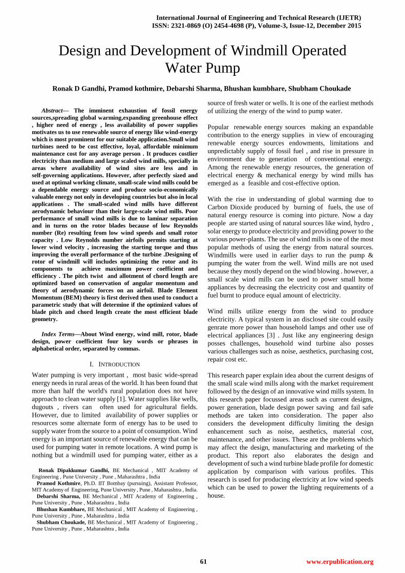
F. Pvc Pipe:-
The cutted PVC pipe at an angle of 32 degree is use
to make turbine. The pipe used for turbine is a PVC material.
The pipe is 110 mm in diameter and 3, in thickness. These are
the light weight pipes which rotate freely by wind.
International Journal of Engineering and Technical Research (IJETR)
ISSN: 2321-0869 (O) 2454-4698 (P), Volume-3, Issue-12, December 2015
73 www.erpublication.org
Figure No 25: PVC Blade
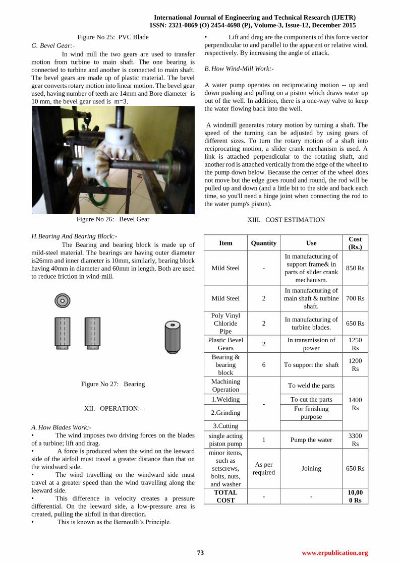
G. Bevel Gear:-
In wind mill the two gears are used to transfer
motion from turbine to main shaft. The one bearing is
connected to turbine and another is connected to main shaft.
The bevel gears are made up of plastic material. The bevel
gear converts rotary motion into linear motion. The bevel gear
used, having number of teeth are 14mm and Bore diameter is
10 mm, the bevel gear used is m=3.
Figure No 26: Bevel Gear
H. Bearing And Bearing Block:-
The Bearing and bearing block is made up of
mild-steel material. The bearings are having outer diameter
is26mm and inner diameter is 10mm, similarly, bearing block
having 40mm in diameter and 60mm in length. Both are used
to reduce friction in wind-mill.
Figure No 27: Bearing
XII. OPERATION:-
A. How Blades Work:-
• The wind imposes two driving forces on the blades
of a turbine; lift and drag.
• A force is produced when the wind on the leeward
side of the airfoil must travel a greater distance than that on
the windward side.
• The wind travelling on the windward side must
travel at a greater speed than the wind travelling along the
leeward side.
• This difference in velocity creates a pressure
differential. On the leeward side, a low-pressure area is
created, pulling the airfoil in that direction.
• This is known as the Bernoulli’s Principle.
• Lift and drag are the components of this force vector
perpendicular to and parallel to the apparent or relative wind,
respectively. By increasing the angle of attack.
B. How Wind-Mill Work:-
A water pump operates on reciprocating motion -- up and
down pushing and pulling on a piston which draws water up
out of the well. In addition, there is a one-way valve to keep
the water flowing back into the well.
A windmill generates rotary motion by turning a shaft. The
speed of the turning can be adjusted by using gears of
different sizes. To turn the rotary motion of a shaft into
reciprocating motion, a slider crank mechanism is used. A
link is attached perpendicular to the rotating shaft, and
another rod is attached vertically from the edge of the wheel to
the pump down below. Because the center of the wheel does
not move but the edge goes round and round, the rod will be
pulled up and down (and a little bit to the side and back each
time, so you'll need a hinge joint when connecting the rod to
the water pump's piston).
XIII. COST ESTIMATION
Item Quantity Use Cost
(Rs.)
Mild Steel -
In manufacturing of
support frame& in
parts of slider crank
mechanism.
850 Rs
Mild Steel 2
In manufacturing of
main shaft & turbine
shaft.
700 Rs
Poly Vinyl
Chloride
Pipe
2 In manufacturing of
turbine blades. 650 Rs
Plastic Bevel
Gears 2
In transmission of
power
1250
Rs
Bearing &
bearing
block
6 To support the shaft 1200
Rs
Machining
Operation
-
To weld the parts
1400
Rs
1.Welding To cut the parts
2.Grinding For finishing
purpose
3.Cutting
single acting
piston pump 1 Pump the water
3300
Rs
minor items,
such as
setscrews,
bolts, nuts,
and washer
As per
required Joining 650 Rs
TOTAL
COST - -
10,00
0 Rs

Design and Development of Windmill Operated Water Pump
74 www.erpublication.org
XIV. WORK PLAN
SR
NO DESCRIPTION TOTAL TIME
1 Analytical study 1.5 Months ( June-July)
2 Designing 2 Months
(August-October)
3 Fabrication 2.5 Months
(November-Jan.)
4 Experimentation 2.5 Months
(January-March)
5 Final Report
Preparation 0.5 Months ( April)
6 TOTAL
DURATION 9 Months (June-April)
REFERENCES
[1] U.S. Department of Energy. “Wind and Hydropower Technologies
Program” Retrieved from
http://eereweb.ee.doe.gov/windandhydro/wind_how.html in
November, 2005.
[2]
http://practicalaction.org/docs/technical_information_service/windp
umps
[3] T H Taylor, Alternate Energy Sources, Adam Hilger Ltd, Bristol, 2001
[4] Wind Power Workshop: Building Your Own Wind Turbine by Hugh
Piggott Centre for Alternative Technology Publications, 2011
[5] F. Manwell, Jon G. McGowan & Anthony L.,Wind Energy Explained:
Theory, Design and Application, James Rogers Pub, John Wiley and
sons Ltd., 2002
[6] E. Hau, Wind Turbines: Fundamentals, Technologies, Applications,
Economics, Springer Verlag, 29-Feb-2012
[7] Kirke, Brian Kinloch, 1998. “Evaluation of Self-Starting Vertical Axis
Wind Turbines for Stand-Alone Applications”. Griffith University,
Australia. Retrieved (taken) from
http://www4.gu.edu.au:8080/adt-root/public/adt-QGU20050916.120
408/ on November 1, 2005.
[8] Pawsey, N.C.K., 2002. “Development and Evaluation of Passive
Variable-Pitch Vertical Axis Wind Turbines”, School of Mechanical
and Manufacturing Engineering,
[9] Giguere P, Selig MS. New airfoils for small horizontal axis wind turbines
ASME Journalof Wind Energy Engineering 1998;120:108e14.
[10] Elizondo J, Martinez J, Probst O. Experimental study of a small wind
turbine for low- and medium-wind regimes. International Journal of
Energy Research 2009;33:309e26.
[11].U.S. Department of Energy. “Wind and Hydropower Technologies
Program”. Retrieved from
http://eereweb.ee.doe.gov/windandhydro/wind_how.html
[12] Wikipedia Encyclopedia. Retrieved from
http://en.wikipedia.org/wiki/Image:HDarrieus-Rotor.png.jpg on
November 28, 2005.
[13] Chang, Professor L. (2005) “Advanced Topics in Environmental
Engineering -
[14] Wind Power,” Ch. 4. University of New Brunswick. Retrieved from
http://www.ece.unb.ca/powereng/courses/EE6693/index.html
[15] http://www.av8n.com/how/htm/airfoils.html in November 2005.
[16] Sheldahl, Robert E., Klimas, Paul C., 1981. “Aerodynamic
Characteristics ofSeven Symmetrical Airfoil Sections Through
180-Degree Angle of Attack for Use in Aerodynamic Analysis of
Vertical Axis Wind Turbines”, Sandia National Laboratories,
Albuquerque, NM., USA.
[17] Wind Power Workshop: Building Your Own Wind Turbine by Hugh
Piggott Centre for Alternative Technology Publications, 2011
[18] Paul Gipe Chelsea, Wind energy basics: A guide to small and micro
wind systems, Green Pub. Co., 1999.
[19] F. Manwell, Jon G. McGowan & Anthony L.,Wind Energy Explained:
Theory, Design and Application, James Rogers Pub, John Wiley and
sons Ltd., 2002
[20]Paul Gipe, Wind Power: Renewable Energy for Home, Farm, and
Business, Chelsea Green Pub. Co., 2005
Ronak Dipakkumar Gandhi, BE Mechanical , MIT
Academy of Engineering , Pune University , Pune , Maharashtra , India
Pramod Kothmire, Ph.D. IIT Bombay (pursuing),
Assistant Professor, MIT Academy of Engineering, Pune University , Pune ,
Maharashtra , India
Debarshi Sharma, BE Mechanical , MIT Academy
of Engineering , Pune University , Pune , Maharashtra , India
Bhushan Kumbhare, BE Mechanical , MIT,
Academy of Engineering , Pune University , Pune , Maharashtra , India
Shubham Choukade, BE Mechanical , MIT
Academy of Engineering, Pune University , Pune , Maharashtra , India