design and development of storage management system …umpir.ump.edu.my/7587/1/cd7750.pdf · design...
TRANSCRIPT

DESIGN AND DEVELOPMENT OF STORAGE MANAGEMENT SYSTEM AT
FKP
NORZAMIRAH BINTI KAMARUZAMAN
Report submitted in fulfillment of the requirements
for the award of the degree of
Bachelor of Manufacturing Engineering
Faculty of Manufacturing Engineering
UNIVERSITI MALAYSIA PAHANG
JUNE 2013
viii
ABSTRACT
This research covers the development of the storage management system in Faculty of
Manufacturing Engineering (FKP) laboratory. Concepts of this project are to create one
tool storage system to enhance the efficiency of storage management at FKP laboratory.
The aims of this research are to develop and analysis before and after implement storage
management system at FKP laboratory. There are three phase in this system. Phase I
cover the system using the Graphical User Interface (GUI) and Visual Basic (VB)
software, Phase II is the interface between the system and hardware using the Peripheral
Interface Controller (PIC) microcontroller and solenoids. Phase III is built and
implement the system at the hardware. To validate this system, one survey and accuracy
test has been made. Feedbacks from the survey shows 97% to 99% users satisfied and
highly recommended this system implement at FKP laboratory. This system has been
test two hundred times which include two cycles for accuracy test and the results shows
the actual movement of the solenoid and yellow Light-emitting Diode (LED) for the
first and second drawer. The results show that the system is functional between 97% to
99%. By a proper design, this system can be implementing at FKP laboratory and offers
many benefits to the users especially for lecturers and students.
ix
ABSTRAK
Kajian ini meliputi pembangunan sistem pengurusan system simpanan di dalam makmal
Fakulti Kejuruteraan Pembuatan (FKP). Konsep projek ini adalah untuk mewujudkan
satu sistem penyimpanan mata alat untuk meningkatkan kecekapan pengurusan
penyimpanan di makmal FKP. Tujuan kajian ini adalah untuk membangunkan dan
menganalisa sebelum dan selepas di dalam melaksanakan sistem pengurusan
penyimpanan mata alat di makmal FKP. Terdapat tiga fasa dalam sistem ini. Fasa I
merangkumi sistem penggunaan Graphical User Interface (GUI) dan Visual Basic (VB),
Fasa II adalah perantara di antara sistem dan perkakasan menggunakan mikropengawal
Peripheral Interface Controller (PIC) dan solenoid. Fasa III dibina dan melaksanakan
sistem itu pada perkakasan. Untuk mengesahkan sistem ini, satu kaji selidik dan ujian
ketepatan telah dibuat. Maklum balas daripada kajian menunjukkan 97% kepada 99%
pengguna berpuas hati dan amat menyarankan sistem ini dilaksanakan di makmal FKP.
Sistem ini juga telah diuji sebanyak dua ratus kali yang merangkumi dua pusingan
untuk menguji ketepatan dan keputusan yang menunjukkan pergerakan sebenar solenoid
dan Light-emitting Diode (LED) kuning untuk laci yang pertama dan kedua. Keputusan
menunjukkan system ini berfungsi diantara 97% kepada 99%. Dengan reka bentuk yang
betul, sistem ini boleh dilaksanakan di makmal FKP dan menyumbangkan banyak
faedah kepada pengguna terutamanya kepada pensyarah dan pelajar.

x
TABLE OF CONTENTS
Page
EXAMINER’S APPROVAL DOCUMENT
SUPERVISOR’S DECLARATION
iii
iv
STUDENT’S DECLARATION
DEDICATION
v
vi
ACKNOWLEDGEMENTS vii
ABSTRACT viii
ABSTARK ix
TABLE OF CONTENTS x
LIST OF TABLES xiii
LIST OF FIGURES xiv
LIST OF SYMBOLS xvii
LIST OF ABBREVIATIONS xviii
CHAPTER 1 INTRODUCTION
1.1 Background 1
1.2 Problem Statement 3
1.3 Objectives 3
1.4 Scope of Project 3
CHAPTER 2 LITERATURE REVIEW
2.1 Introduction 5
2.2 An Overview of Storage Management System 5
2.3 Previous Research 6
2.3.1 Existed Systems
2.3.1.1 Internet controlled robotic arm 8
2.3.1.2 A Graphical User Interface design for network
simulation
13
2.3.1.3 Graphical User Interfaces in an Engineering
Environmental
19
2.3.1.3.1 Visual FORTRAN 23
2.3.1.3.2 Visual Basic 23

xi
2.3.1.3.3 Visual C++ 24
2.3.1.3.4 Visual J++ 25
2.3.1.3.5 MATLAB 25
2.3.1.4 GUI based automatic remote control of gas
reduction system using PIC microcontroller
26
2.3.1.5 PIC microcontroller: CCP modules 31
2.4 Summary 34
CHAPTER 3 METHODOLOGY
3.1 Introduction 36
3.2 Phases 39
3.2.1 Phase I: Interface from PC 39
3.2.2 Phase II: The designing the system 47
3.2.2.1 PIC microcontroller board 49
3.2.2.2 Light-emitting Diode (LED) 51
3.2.2.3 Solenoid Valve 53
3.2.3 The hardware 55
3.3 Tests 56
3.3.1 Accuracy test 56
3.3.2 Survey test 57
CHAPTER 4 RESULTS AND DISCUSSIONS
4.1 Introduction 59
4.2 Product Information 59
4.2.1 GUI as The Interface 62
4.2.2 Electrical and Electronic Part 67
4.3 Testing 70
4.3.1 Accuracy Test 70
4.3.2 Survey Test 71
4.4 Analysis and Troubleshooting 75
4.5
Achievement 75
CHAPTER 5 CONCLUSIONS AND RECOMMENDATIONS
5.1 Introduction 77

xii
5.2 Conclusion 77
5.3 Problem Encountered 78
5.4 Recommendations 79
REFERENCES 80
APPENDICES 82
A Figures of Streamfunction 82
B Sample of Survey Form 89
C1 Coding of Visual Basic 91
C2 Output Circuit for Part B 96
D Figure of PIC microcontroller circuit board 97
E Gantt Chart 98

xiii
LIST OF TABLES
Table No.
2.1
2.2
Title
Specification of internet controlled robotic arm
Computational run-time in seconds of each different
programming language for the driven cavity flow problem with
standard deviation in parenthesis
Page
10
22
3.1
3.2
Function for drawer system page
Light-emitting Diode (LED) specification
42
52

xiv
LIST OF FIGURES
Figure No.
2.1
2.2
2.3
2.4
2.5
2.6
2.7
2.8
2.9
2.10
2.11
2.12
2.13
2.14
2.15
2.16
2.17
Title
Project overview of internet controlled robotic arm
Specific block diagram of internet controlled robotic arm
Completed internet controlled robotic arm
Completed GUI for internet controlled robotic arm
The Internet Controlled Arm
Communication between Command Interpreter (CI) and
GUI
Communicating using the CommChannel
Syntax of the GUI Dialog File
Driven cavity problem used as benchmark to measure the
computational efficiency of each lower level language
Local control panel of GRS
Local control panel of GRS
The block of proposed system
Illustrates C program writing in MPLAB version 8.33
The GUI design for monitoring and controlling GRS
Capture mode operating of CCPx module
Capturing Rising Edge Event
Filter circuit where analog output required
Page
9
10
11
12
12
14
15
19
21
27
28
29
29
30
32
33
34
xv
3.1
3.2
3.3
3.4
3.5
3.6
3.7
3.8
3.9
3.10
3.11
3.12
3.13
3.14
3.15
3.16
3.17
4.1
4.2
4.3
4.4
4.5
4.6
The overall process
Flow Chart for the whole process
System from PC flow chart
Overall of drawer system (phase I)
First time log-in procedures
Add new item procedures
Edit current item procedures
Request item procedures
Delete item procedures
Flow Chart for the Interface
PIC Microcontroller Board
Part A (PIC microcontroller board)
Part B (PIC Microcontroller Board)
Yellow Light-emitting diode (LED) 10mm diameter
Solenoid valve
The Flow Chart for Hardware
The Overall Planning for Allocate the Interface
The hardware and the system of the final project
Overall of drawer system using GUI as the interface
Implement phase II into phase III
Printed circuit board (PCB) of the project
The coding for add new item button
The coding for save item button
37
38
40
41
45
45
46
46
47
48
49
50
51
51
53
55
56
60
60
61
61
63
64

xvi
4.7
4.8
4.9
4.10
4.11
4.12
4.13
4.14
4.15
4.16
4.17
4.18
4.19
4.20
4.21
The coding for the search button
The coding for the edit button
The coding for delete button
The coding for request button
The coding for availability update information
Overall of PIC microcontroller circuit board (PCB)
The coding for PIC microcontroller 16f887 for receiving
availability of the ram
The coding for PIC microcontroller 16f887 for checking and
transmit the availability of the ram
Graph for accuracy test
Members of UMPian
Question 01-06 feedback
Questions 07-13 feedback
Drawer system outlook
Questions 14-18 feedback
Hardware
64
65
66
66
67
67
68
69
71
72
72
73
74
74
75
xvii
LIST OF SYMBOLS
%
Percentage
“
Inch
cm
Centimetre
D
Diameter
G
Giga
g
Gram
Hz
Hertz
L
Length
M
Mega
Max
Maximum
N/A
Not Applicable
oC
Degree Celsius
sec
Second
u
Inertia
V
Voltage
v
Velocity
xviii
LIST OF ABBREVIATIONS
A/D
Analog-to-Digital
ADC
Alternating Direct Current
API
Application Program Interface
AS/R
Automated Storage Retrieval
CCP
Capture/Compare/PWM
CFD
Computational Fluid Dynamics
CI
Command Interpreter
COPS
Computer Operation Performance System
DC
Direct current
EPS
Earnings Per Share
FKP
Fakulti Kejuruteraan Pembuatan
FORTRAN
Formula Translating System
FPWM
Fast Pulse Width Modulation
GRS
Gas Reduction System
GUI
Graphical User Interface
GUIDE
Graphical User Interface Development Environment
HMI
Human Machine Interface
HTML
HyperText Markup Language
I/O
Input-to-Output
IBM
International Business Machine
IDE
Integrated Development Environment
IFR International Federation of Robotic
IP
Internet Protocol

xix
IPC
Inter Process Communication
LED
Light-emitting Diode
MATLAB
Matrix Laboratory
MCR
MATLAB Component Run-Time
MFC
Microsoft Foundation Classes
OOP
Object-Oriented Programming
PC
Personal Computer
PCB
Printed Circuit Board
PIC
Peripheral Interface Circuit
PWM
Pulse Width Modulation
RAM
Random Access Memory
RISC
Reduced Instruction Set CPU
RPM
Revolution Per Minute
SPI
Serial Peripheral Interface Bus
TMR
Triple-Mode Redundancy
UMP
Universiti Malaysia Pahang
USART
Universal Synchronous/Asynchronous Receiver/Transmitter
USB
Universal Serial Bus
VB
Visual Basic
VRML
Virtual Reality Modelling Language

1
CHAPTER 1
INTRODUCTION
1.1 BACKGROUND
Storage system has grown to the point where failures are common place and
must be tolerated to prevent data loss. All current storage systems that are composed of
multiple components employ erasure codes to handle disk failure. Storage systems are
inevitable for modern day computing. All known computing platforms ranging from
handheld devices to large super computers use storage systems for storing data
temporarily or permanently. Beginning from punch card which stores a few bytes of
data, storage systems have reached to multi Terabytes of capacities in comparatively
less space and power consumption (Plank et al., 2012). Storage when refers to
computers meaning that a device capable of storing data. In a computer, storage is the
place where data is held in an electromagnetic or optical form for access by a computer
processor. Computer data storage also known as storage or memory refer to computer
components, devices and recording media that retain digital data used for computing for
some interval of time (He et al., 2002).
The first data storage device was introduced by International Business Machines
(IBM) in 1956. Since then there has been remarkable progress and has provided the
fertile ground on which the entire industry of storage systems has been built. Storage
systems are built by taking the raw storage capability of a storage device and by adding
layers of hardware and software in order to obtain a system that is highly reliable, has
high performance and easily manageable. Storage systems are sometimes referred to as
storage subsystems or storage devices (Plank et al., 2012). Storage systems have
evolved to support a variety of added services, as well as connectivity and interface

2
alternatives. It is for this reason that file systems and storage management systems are
often considered parts of a storage system (Morris et al., 2003).
Since storage assignment has a direct impact on order picking efficiency, it has
received much interest in the research of distribution warehouse operation, seaport
container yard operation and automated storage and retrieval (AS/R) systems (Chou et
al., 2011). A main advantage of the dedicated storage policy is that order pickers can
learn the inventory locations quicker. In applying the dedicated storage policy,
inventory items are ranked by certain indices and then assigned to the storage slots
sequentially according to the rank (Chou et al., 2011).
Starting from the establishment of the Faculty of Manufacturing Engineering
(FKP) on 2008 until now, there is no store keeper was been hired. Other than that, users
faced with some other problem regarding the store at FKP such as lack of tool
information, difficult to find the tool, take a long time to find the location of tool, the
quantity of the tool needed is not enough and tool misplace. Storekeeper is responsible
in storing, releasing, compiles records, monitoring and controlling tools. By implement
this tool storage system in FKP, inventories will be placed in the safety, appropriate,
conspicuous and neatly. Other than that, by implementing tool storage system at the
FKP workshop, it can be reduce to hiring store keeper. FKP also can get lot of
advantages by implementing storage management system such as easy to find the
location, specification and details information of the tool. Due to the tool arrangement it
can be in a systematic, proper, innovative and appropriate condition.
1.2 PROBLEM STATEMENT
This is concerned with the problem of the development tool storage system. The
items are used in a given process, which incurs a cost whenever the required item is not
immediately available or in bad condition (Matzliach., 1998).
The different problem in which the request for the same stock items is
stochastically recurrent. Examples of such items include tooling in factory, books in
library and digital objects in data warehouse or store (Chou et al., 2011).

3
In Faculty of Manufacturing Engineering (FKP) store, there is no other proper
system to keep those tools storage especially tooling in a systematic and economic
method. The tools that have in the store like end mill, ball nose, taping with various
types of diameter, reamer, phase mill, turning tool, boring tool, tape holder, vanier
caliper, micrometer, air gun and many more. Users just take the tool needed and not
return back to the original location. Hence, it will give difficulty to the next user to find
the tool. Therefore, if it still no other proper system has been created to overcome this
problem, FKP will faced with a bad impact in storage management system especially on
tooling which are store will unorganized, full with necessaries and unnecessary tools,
waste of time and money uses to buy or order from suppliers. The FKP will face huge
losses because of those bad impacts and missing tools.
This study is made to develop a system to keep all the tool storage in order,
more systematic, more appropriate storage, easy to find the storage and able to control
the storage via system. In addition, this research can be improve a lot from the storage
flow in FKP due to the management and education aspect and also it become more
efficient in storage management. According to the FKP administrator, no one are
interested to manage the FKP storage because there are no specific journals on this
research, only limited study can be found and no specific software provided. This
information can be very useful to people whose intend to do improvement at their place.
With applying this method in FKP, it will solve those problems that occur
1.3 OBJECTIVES
The main objectives of this research are:
i. To develop and analysis the hardware of tool storage system.
ii. To compare the results before and after applying this tool storage system.

4
1.4 SCOPE OF PROJECT
The following scopes of the project are determined in order to achieve the
objectives of the project. The system that has been recommended for implementing the
tool storage system at Faculty of Manufacturing Engineering (FKP) is by using system
and hardware. Due to safety and limiting of budget aspect, this project will held only in
prototype. This project is dividing into three phases which are the interface of phase I,
designing the system for phase II and the hardware for phase III. It is limiting for
searching and taking once per one tool only. For phase I, the interface that has been
recommended is using Graphical User Interface (GUI). This system is specifically
created for searching and finding the presence of the tools through the computer. There
are thirty (30) items of tools are recorded in the database.The software that be used for
this system is Visual Basic (VB). VB is created to check the existence of tool and also
giving the details information and the status for the tools to avoid clash user among the
staffs and students. The programming interprets and sends to the Peripheral Interface
Controller (PIC) and in phase II. Phase II where the PIC microcontroller board will take
part to accept and interpret the data given from GUI. Once the data has been trigger,
PIC microcontroller will send back the data to the phase I. The software that be used is
microC PRO for PIC. The programming will analyze and give command to the
electronics components to function. The electronics components playing the important
role to connect from the phase II to phase III. Phase III is the hardware where the
installation of the PIC microcontroller board to the cabinet. This cabinet indicates two
drawers to allocate the tools.
.

5
CHAPTER 2
LITERATURE REVIEW
2.1 INTRODUCTION
This chapter discussed about the storage management system that implement at
the Faculty of Manufacturing Engineering (FKP). This chapter gives a brief explanation
about the concepts and methods on how to build this project. This chapter also provides
a review of past research efforts related to storage management system study and also
the important criteria that need to consider when creating the concepts and methods.
From the related journals and articles, the idea in creating the concepts and methods of
storage management systems at FKP can be more systematics and as an aid in
completing this project.
2.2 AN OVERVIEW OF STORAGE MANAGEMENT SYSTEM
Traditionally, when storage systems employ erasure codes, they are designed to
tolerate the failures of entire disks. Storage systems have grown to the point where
failures are common place and must be tolerated to prevent data loss. All current storage
systems that are composed of multiple components employ erasure codes to handle disk
failure (Plank et al., 2012).
There are five main categories of storage system policies: random storage, closet
open location storage, dedicated storage, full-turnover-based storage and class-based
storage. A main advantage of the dedicated storage policy is that order pickers can learn
the inventory locations quicker. In applying the dedicated storage policy, inventory
items are ranked by certain indices and then assigned to the storage slots sequentially
according to the rank (Chou et al., 2011).

6
Distributed storage systems usually consist of a large amount of commodity
computer nodes which may have different processing capabilities. However, the overall
performance of such systems is not determined by the fastest computer nodes of the
systems, instead, the performance is often limited by the capability of the slowest ones.
So, if there exists performance anomaly in some node of a distributed storage system, it
is highly possible that the overall system performance will suffer negative effects, and
such effects may be accumulated and magnified due to long-running and large-scale
computations, which directly hurts the reliability and availability of the system.
Therefore, it is necessary and crucial to equip distributed storage systems with a tool
which is able to efficiently detect performance anomaly and accurately identify the
faulty sources (Chen et al., 2010).
2.3 PREVIOUS RESEARCH
Previous work shown there are many projects based on the concepts and
methods of this project. A proceeding engineering from Wan et al. (2012) which is
based on a concept of an internet controlled robotic arm. This journal is the movement
of the robot arm can be controlled by a computer via the internet. This robot can be used
to demonstrate that a robot can be used inside a home for daily human chores. The robot
is controlled by Arduino Uno that interfaced with the internet using Arduino Ethernet
Shield. Two type of analysis were done for this project that is servo motor analysis and
accuracy test. The accuracy test shows that the results of the actual output of the servo
motor as compared to the input send to Arduino Uno via internet is between 97% to
99%. In this research, accuracy test is conducted to check out how the accurate the
servo motors are when a new position value is send to Arduino Uno via the internet
from a computer.
From the article consist of Lin et al. (1997) describes a how Graphical User
Interface (GUI) act as a system. The prototyping effort of a flexible GUI for a
simulation tool called COPS. The GUI is designed to allow parameter setup for all
modules in simulation model, and can be easily replaced by new GUls implemented in
different languages/graphical tools. This article provides design guidelines and
implementation details of the flexible GUI.
7
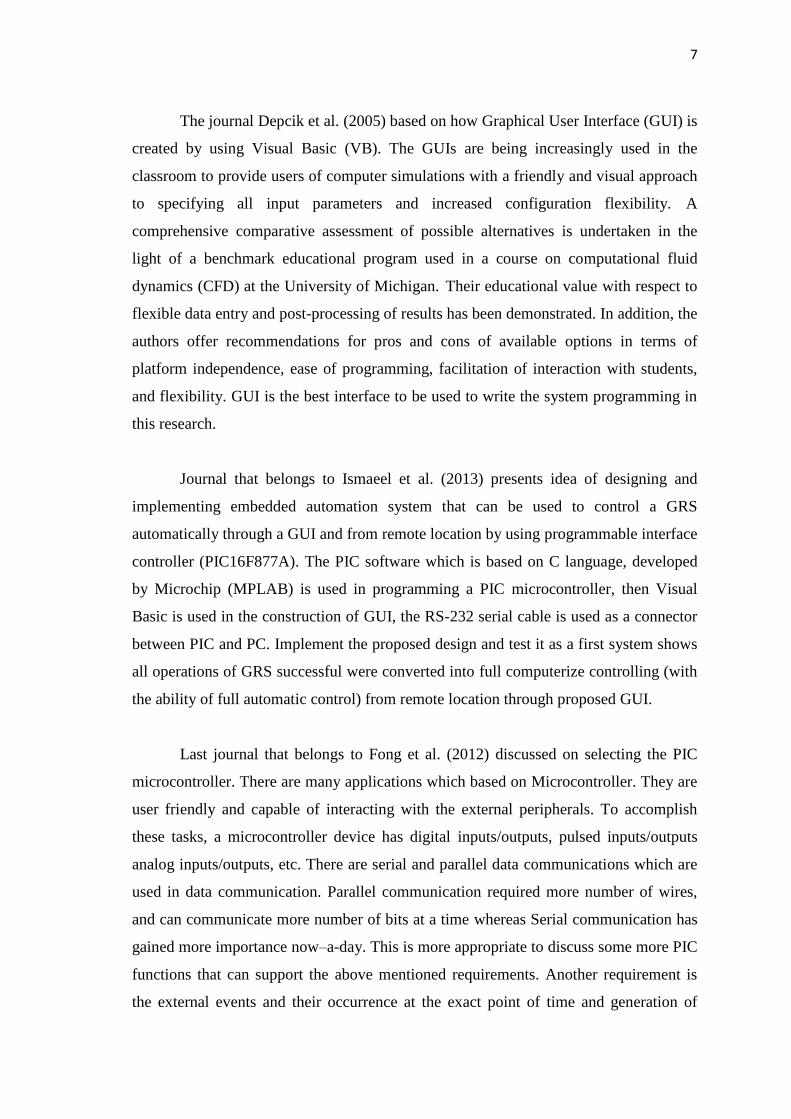
The journal Depcik et al. (2005) based on how Graphical User Interface (GUI) is
created by using Visual Basic (VB). The GUIs are being increasingly used in the
classroom to provide users of computer simulations with a friendly and visual approach
to specifying all input parameters and increased configuration flexibility. A
comprehensive comparative assessment of possible alternatives is undertaken in the
light of a benchmark educational program used in a course on computational fluid
dynamics (CFD) at the University of Michigan. Their educational value with respect to
flexible data entry and post-processing of results has been demonstrated. In addition, the
authors offer recommendations for pros and cons of available options in terms of
platform independence, ease of programming, facilitation of interaction with students,
and flexibility. GUI is the best interface to be used to write the system programming in
this research.
Journal that belongs to Ismaeel et al. (2013) presents idea of designing and
implementing embedded automation system that can be used to control a GRS
automatically through a GUI and from remote location by using programmable interface
controller (PIC16F877A). The PIC software which is based on C language, developed
by Microchip (MPLAB) is used in programming a PIC microcontroller, then Visual
Basic is used in the construction of GUI, the RS-232 serial cable is used as a connector
between PIC and PC. Implement the proposed design and test it as a first system shows
all operations of GRS successful were converted into full computerize controlling (with
the ability of full automatic control) from remote location through proposed GUI.
Last journal that belongs to Fong et al. (2012) discussed on selecting the PIC
microcontroller. There are many applications which based on Microcontroller. They are
user friendly and capable of interacting with the external peripherals. To accomplish
these tasks, a microcontroller device has digital inputs/outputs, pulsed inputs/outputs
analog inputs/outputs, etc. There are serial and parallel data communications which are
used in data communication. Parallel communication required more number of wires,
and can communicate more number of bits at a time whereas Serial communication has
gained more importance now–a-day. This is more appropriate to discuss some more PIC
functions that can support the above mentioned requirements. Another requirement is
the external events and their occurrence at the exact point of time and generation of
8
precise timing at the output pins of the microcontroller on a real time. There are two
CCP modules in 16F877 supporting capture/compare and PWM functions discuss in
present paper. This module allows detecting exact timing of the occurrence of an event
or can generate exact timing at the output.
2.3.1 Existed Systems
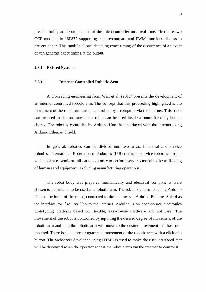
2.3.1.1 Internet Controlled Robotic Arm
A proceeding engineering from Wan et al. (2012) presents the development of
an internet controlled robotic arm. The concept that this proceeding highlighted is the
movement of the robot arm can be controlled by a computer via the internet. This robot
can be used to demonstrate that a robot can be used inside a home for daily human
chores. The robot is controlled by Arduino Uno that interfaced with the internet using
Arduino Ethernet Shield.
In general, robotics can be divided into two areas, industrial and service
robotics. International Federation of Robotics (IFR) defines a service robot as a robot
which operates semi- or fully autonomously to perform services useful to the well-being
of humans and equipment, excluding manufacturing operations.
The robot body was prepared mechanically and electrical components were
chosen to be suitable to be used as a robotic arm. The robot is controlled using Arduino
Uno as the brain of the robot, connected to the internet via Arduino Ethernet Shield as
the interface for Arduino Uno to the internet. Arduino is an open-source electronics
prototyping platform based on flexible, easy-to-use hardware and software. The
movement of the robot is controlled by inputting the desired degree of movement of the
robotic arm and then the robotic arm will move to the desired movement that has been
inputted. There is also a pre-programmed movement of the robotic arm with a click of a
button. The webserver developed using HTML is used to make the user interfaced that
will be displayed when the operator access the robotic arm via the internet to control it.

9
The robot has been design to mimic the movement of a human arm. This section
will present a full description of the hardware of the robot design and it is divided into
two main sections: mechanical and electrical design. In this project, the hardware and
software function are combined to make the system reliable. Arduino Uno is the brain
of this project and Arduino Ethernet Shield interfaced Arduino Uno with the internet.
The project overview of internet controlled the robotic arm is shown in Figure 2.1.
Figure 2.1: Project overview of internet controlled robotic arm
Source: Wan et al., 2012
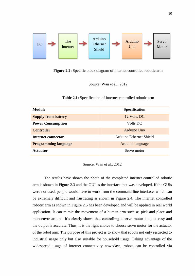
The block diagram in Figure 2.2 shows the specific block diagram of the robotic
arm. While Table 2.3 shows the specification of internet controlled robotic arm. Primary
source of power for the robot is a 12V/1.2Ah Lead Acid battery because of its
characteristics and advantages. The main source then is regulated to 5V using voltage
regulator LM78XX. Servo motor is one of the DC type motors with feedback that used
in many applications that required controlling the system in up-down direction. Servos
are extremely useful in robotics. Servo motor provides low RPM with high torque.
Since the high torque is essential for this project. Therefore servo motor 180 is preferred
in this project.
Arduino Uno
Computer Arduino Ethernet
Shield
Robotic Arm
Servo Motor
Internet
10
Figure 2.2: Specific block diagram of internet controlled robotic arm
Source: Wan et al., 2012
Table 2.1: Specification of internet controlled robotic arm
Module Specification
Supply from battery 12 Volts DC
Power Consumption Volts DC
Controller Arduino Uno
Internet connector Arduino Ethernet Shield
Programming language Arduino language
Actuator Servo motor
Source: Wan et al., 2012
The results have shown the photo of the completed internet controlled robotic
arm is shown in Figure 2.3 and the GUI as the interface that was developed. If the GUIs
were not used, people would have to work from the command line interface, which can
be extremely difficult and frustrating as shown in Figure 2.4. The internet controlled
robotic arm as shown in Figure 2.5 has been developed and will be applied in real world
application. It can mimic the movement of a human arm such as pick and place and
manoeuvre around. It‟s clearly shows that controlling a servo motor is quiet easy and
the output is accurate. Thus, it is the right choice to choose servo motor for the actuator
of the robot arm. The purpose of this project is to show that robots not only restricted to
industrial usage only but also suitable for household usage. Taking advantage of the
widespread usage of internet connectivity nowadays, robots can be controlled via
PC The
Internet
Arduino
Ethernet
Shield
Arduino
Uno
Servo
Motor

11
internet instead of a dedicated controller just for the robots. This project was successful
and proved that robots can be controlled via internet and it is suitable for household
usage.
Figure 2.3: Completed internet controlled robotic arm
Source: Wan Kadir et al., 2012