design and development of a low-cost inspection robot
TRANSCRIPT
Design and Development of a Low-Cost
Inspection Robot
Nikhil Devanathan

Acknowledgements
I wish to acknowledge my parents, Ram Devanathan and Subha Narayanan, for helping me by
providing materials and equipment, reviewing my design, providing guidance, answering
questions, offering pointers, instructing me on data analysis, taking photographs, and proof
reading my written material.
I thank Mr. Michael Thien for patiently answering my questions about the Hanford Tanks and
robot design/constraints, and for guiding me in my project. I also wish to thank Dr. A. David
McKinnon for his feedback about my robot and the code running the robot.
All photographs associated with this project, shown in this report and the poster display, were
taken by me or by my parents.

Contents Abstract ........................................................................................................................................................ 1
1. Introduction ............................................................................................................................................. 2
2. Literature Review ................................................................................................................................... 3
3. Specification of Requirements ............................................................................................................... 6
4. Design and Development of the Robot .................................................................................................. 7
4.1. Prototype 1: LEGO EV3 .................................................................................................................... 7
4.2 Material and Component Selection for the Second Prototype ............................................................ 9
4.3 Computer Aided Design (CAD) of the Second Prototype ................................................................ 11
4.4 Prototype 2a: Pre-Made Chassis ....................................................................................................... 12
Building Prototype 2a ......................................................................................................................... 12
Wiring Prototype 2a ............................................................................................................................ 14
Programming Prototype 2a ................................................................................................................. 15
Testing Prototype 2a ........................................................................................................................... 21
4.5 Engineering Mechanics Calculations ................................................................................................ 22
Force and Torque Equations ............................................................................................................... 22
Force Calculation for Magnet Placement ............................................................................................ 23
Torque Calculation for Motor Selection ............................................................................................. 24
4.6 Prototype 2b: Pre-Made Chassis ....................................................................................................... 25
Building Prototype 2b ......................................................................................................................... 25
Wiring Prototype 2b ............................................................................................................................ 26
Programming Prototype 2b ................................................................................................................. 27
Testing Prototype 2b ........................................................................................................................... 32
4.7 Prototype 3: Custom Polycarbonate Chassis .................................................................................... 34
Testing Prototype 3 ............................................................................................................................. 42
5. Conclusion and Outlook ....................................................................................................................... 45
6. Bibliography .......................................................................................................................................... 46
7. Appendix ................................................................................................................................................ 47
Appendix I: Xbox Controller Code ......................................................................................................... 47
Appendix II: Motor Test Code ................................................................................................................ 61
Appendix III: SNES Controller Code ..................................................................................................... 62
1
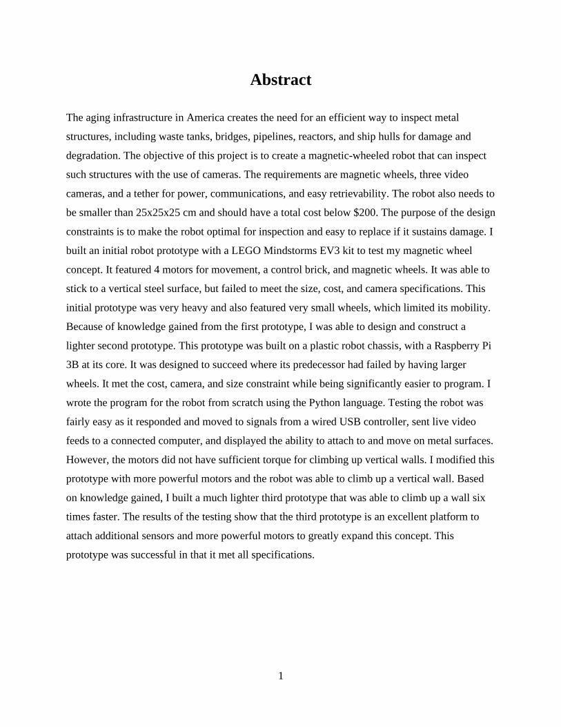
Abstract
The aging infrastructure in America creates the need for an efficient way to inspect metal
structures, including waste tanks, bridges, pipelines, reactors, and ship hulls for damage and
degradation. The objective of this project is to create a magnetic-wheeled robot that can inspect
such structures with the use of cameras. The requirements are magnetic wheels, three video
cameras, and a tether for power, communications, and easy retrievability. The robot also needs to
be smaller than 25x25x25 cm and should have a total cost below $200. The purpose of the design
constraints is to make the robot optimal for inspection and easy to replace if it sustains damage. I
built an initial robot prototype with a LEGO Mindstorms EV3 kit to test my magnetic wheel
concept. It featured 4 motors for movement, a control brick, and magnetic wheels. It was able to
stick to a vertical steel surface, but failed to meet the size, cost, and camera specifications. This
initial prototype was very heavy and also featured very small wheels, which limited its mobility.
Because of knowledge gained from the first prototype, I was able to design and construct a
lighter second prototype. This prototype was built on a plastic robot chassis, with a Raspberry Pi
3B at its core. It was designed to succeed where its predecessor had failed by having larger
wheels. It met the cost, camera, and size constraint while being significantly easier to program. I
wrote the program for the robot from scratch using the Python language. Testing the robot was
fairly easy as it responded and moved to signals from a wired USB controller, sent live video
feeds to a connected computer, and displayed the ability to attach to and move on metal surfaces.
However, the motors did not have sufficient torque for climbing up vertical walls. I modified this
prototype with more powerful motors and the robot was able to climb up a vertical wall. Based
on knowledge gained, I built a much lighter third prototype that was able to climb up a wall six
times faster. The results of the testing show that the third prototype is an excellent platform to
attach additional sensors and more powerful motors to greatly expand this concept. This
prototype was successful in that it met all specifications.
2
1. Introduction
Our nation’s infrastructure is aging and deteriorating rapidly. Currently there is no
mechanism to thoroughly inspect the condition of our bridges, waste tanks, pipelines, and
reactors. Many of these structures have reached the end of their design life and need to be
inspected for deterioration. Like this situation on land, there is also the need to inspect the hulls
and decks of US Navy ships and oil tankers for signs of corrosion. Many old structures, such as
tall bridges and waste tanks, are often difficult to probe or inspect for a multitude of reasons. The
most common reason is that the inspection process is hazardous to humans, or the structure has
sections that are inaccessible. Another common reason is that current probe technology may be
inadequate to accurately inspect such structures. Thus, manual inspection is infrequent,
laborious, expensive, hazardous and error-prone. This problem offers a perfect opportunity for a
well-made inspection robot.
Inspection robots are typically designed and developed by large well-funded teams of
electrical and mechanical engineers. Commercial robots, such as the Packbot 510
(http://endeavorrobotics.com/products), can cost more than $100,000. Given the constraints of
an individual science fair project, the scope here is to design, develop and test an inexpensive
prototype for an inspection robot. The aim of this project is to develop a small, lightweight
and inexpensive inspection robot prototype that can stay attached to the surfaces to be
inspected. The project is made up of the following tasks: review of literature and existing
designs; specification of requirements; robot design; development of initial prototype and
testing; engineering mechanics calculations; programming the robot using Python; development
and testing of the second prototype; and development and testing of the final prototype.
Before physically building the robot, the 3D modeling software SketchUp was used to
visualize the robot and refine the design. The robot was built from commercial off-the-shelf
components, including a Raspberry Pi 3 module to control the robot. The design was iteratively
improved through repeated testing. Python code was written from scratch to program the robot.
As the design evolved, both the hardware and software had to be modified in tandem. The
prototype was demonstrated to engineering experts at Washington River Protection Solutions
and Pacific Northwest National Laboratory, and the Senior Design Class at Washington State
3
University, Tri Cities. Based on feedback from the experts, engineering mechanics calculations,
and the results of testing, the third prototype was built and programmed. The resulting robot is
able to climb walls at a reasonable speed and has multiple cameras to help with navigation and
inspection. The robot produced by this project represents a unique design with software written
specifically for this purpose. This prototype serves as a flexible platform in that new sensors can
be added as needed to augment the inspection capabilities.
2. Literature Review
Before beginning work on the project, I performed a literature review to evaluate existing
solutions. Currently available probes can be classified into two types – stationary and mobile.
Stationary probes are the most widely used tool for inspecting structures. They provide very
detailed information about a particular section of a structure and can continuously monitor it.
However, once they are positioned in a location, the range of observation will be limited. Due to
the lack of mobility, they are unsuited for monitoring large structures. The other category is
made up of robot mounted probes. These offer a greater degree of functionality as the probe can
be moved freely. Most robots currently on the market are very specialized in a specific task or
kind of inspection. Some robots may specialize in traversing water, high altitudes, or swampy
semi-solid terrain, but none of those robots are useful for structural inspection.
The aquatic inspection robot AQUA1 is a great example. AQUA is a highly specialized
and expensive inspection robot. It crawls on the bed of water bodies and takes 3-dimensional
(3D) scans of its area. It is able to use cameras, sensor scans, and algorithms to follow a
designated path underwater. Despite the fact that it is an inspection robot, it is useless for
structural inspection, since it lacks the ability to climb on ferrous surfaces.
Another example is the AETOS2 aerial drone. The AETOS drone is a quadcopter that is
used for surveying, landscape mapping, and emergency response. The robot itself is a remote
piloted quadcopter that suspends a high-power camera. The camera is able to capture and record
1 http://ieeexplore.ieee.org/document/1389962/?part=1 2 http://www.aetosgroup.com/#air
4
detailed images and videos of structures and landscapes. The AETOS drone is versatile in its
usage and can even inspect exposed structures such as bridges from the air. The disadvantage of
the drone is that it is not ideal for detailed structural inspections, because wind can shift the
drone while it is in the middle of an inspection. The drone is also not usable within enclosed
structures, as it risks crashing. The AETOS drone requires frequent charging and cannot stay
airborne for extended periods of time. It is also expensive, prone to damage, and difficult to
retrieve from a crash.
Some of the currently available robots pack powerful sensors, multiple cameras, and wall
climbing abilities. Such robots are extremely costly and cannot be deployed in large numbers to
perform inspections. The risks of damage associated with these robots and the replacement costs
are also very high. Damage is a very real consideration, because practically every robot
employed to inspect the damaged nuclear reactors at the Fukushima Daiichi site in Japan has
failed as of March 2017. An example of an expensive robot is the MagneBike3. The MagneBike
is a fairly new robot that is not yet sold commercially but is currently in testing and private
development. The MagneBike is a robotic bicycle that features two wheels connected to a main
body by a free joint. This joint allows the robot to move freely on any ferrous surface regardless
of contours. Each wheel also has two levers attached to its sides and resembles training wheels.
The length of each lever is slightly greater than the radius of each wheel. The levers are used to
de-link the wheel from the magnetic surface it is connected to, allowing it to traverse smoothly
on interior angles. The MagneBike can be set up to support a high definition camera and
supports a 3D mapping sensor, that allows it to create a 3D model of its surroundings. The robot
is controlled and powered through a cable and is a tethered device for easy retrievability. The
disadvantage of the MagneBike however, is that it is very difficult to replace if broken, and is
quite expensive if the parts used are anything to go by.
A similar magnetic wheeled robot is the US Navy’s Multi-Segmented Magnetic Robot4
(MSMR). The MSMR is a naval robot designed for ship hull inspection. While the MSMR is not
designed for above ground structural inspection, it could be easily adapted to inspect structures.
Also, inspecting a ship’s hull and inspecting an industrial structure, are not dissimilar tasks. The
3 http://e-collection.library.ethz.ch/eserv/eth:7825/eth-7825-01.pdf 4 http://www.public.navy.mil/spawar/Pacific/Robotics/Documents/Publications/2014/MSMR_MegaRust_2014.pdf
5
MSMR is a 3-segmented robot, with each segment being a metal box containing electronics, with
two wheels attached to its sides. The segments are connected by flexible or jointed connectors.
Each wheel can work independently, and the robot is able to scale 3D obstacles easily when all
wheels work together. The wheels are magnetized and can support the robot. The disadvantages
of the robot are that it does not have a tether and is thus powered only by a battery. This is
disadvantageous, because it makes the robot significantly more difficult to control and limits the
robot’s inspection life. The MSMR is also currently unreleased and used by the Navy only. The
robot will probably remain that way for the foreseeable future.
Another example of an inspection robot is the Omni-Directional Wall-Climbing
Microbot5. The Microbot is a miniscule circular robot weighing in at only 7.2 grams. It has a
diameter of 26 mm and a height of 16.4 mm. The bot is currently in the final stages of testing and
is not yet available commercially. The robot supports 3 magnetic wheeled micromotors with
360° turning capability. The wheels allow it to traverse most ferrous surfaces with ease. The
Microbot can be set up to support a single micro camera. The camera can send back simple
images and videos to the controller. The robot is also tethered. It is connected to its controller by
copper wires that can be insulated for protection. While the robot is inexpensive and can be used
in groups, it only can support a single camera, and the tether is weak. It also lacks any room for
expansion and cannot support any sensors.
There are robot designs that use suction cups or negative pressure generated by propellers
to attach to surfaces. The suction cups offer limited mobility compared to magnetic wheels and
are not suited for heavy robots equipped with multiple cameras and sensors. Moreover, the
suction power will degrade with time due to mechanical wear. The negative pressure system
requires considerable power and constant power. If power is lost, the robot will become
detached from the surface. Each of the designs that has been tried before has its advantages and
disadvantages, but none has solved the inspection problem completely. The literature review
enabled me to survey the landscape, learn about what has been tried before, and come up with
my own design.
5 http://cdn.intechopen.com/pdfs/35516/InTech-An_omni_directional_wall_climbing_microrobot_with_magnetic_wheels_directly_integrated_with_electromagnetic_micromotors.pdf

6
3. Specification of Requirements
The inspection robot would have to meet several constraints. The first constraint on the
robot would be size. An inspection robot would ideally be small. Some of the spaces that the
robot would inspect are less than a foot in width and height. The size is limited in this project to
25x25x25 cm. The smaller size increases the mobility and versatility of the robot in complex
environments, such as bridge beams. An advantage of the small size is also that the robot will
consume less power and be easier to manipulate. The robot would also have to be tethered. A
tethered robot would be able to send more data faster and more reliably than a wireless robot.
The controller of the robot would not have to worry about the robot leaving the range of the
wireless signal, and would also be able to easily extract the robot in case of an accident or
failure. In addition, an inspection robot would have to support multiple cameras for thorough
inspection and navigation. The live camera footage from the robot to the controller would be
necessary for the robot to be accurately driven through the structure it is inspecting, and to warn
the controller of immediate hazards. Another constraint the robot would need to meet is that it
would need to be able to climb on ferrous surfaces. The easiest way to meet that constraint would
be for the robot to have magnetic wheels or a magnetic body thus enabling the robot to scale
ferrous surfaces with ease. This is because ferromagnetic materials, such as mild steel, low alloy
steel and iron, are primary materials in the construction of such structures. Lastly, the robot
should be inexpensive, preferably with a cost under $200. An inexpensive robot is easy to
replace, and when inspecting older structures, it would not be surprising for a robot to get
damaged. An inexpensive robot also means that more robots can be bought and used for a task,
which can increase inspection efficiency greatly.

7
4. Design and Development of the Robot
4.1. Prototype 1: LEGO EV3
In order to design a robot that meets the constraints stated above, I began prototyping
with a LEGO EV3 control module and other LEGO parts. I originally started working with
LEGOs for prototyping because it is easy to build with LEGOs and creating a robot is fairly
simple. The EV3 module is a programable robot core that controls the LEGO robot and was
already available at home. Using LEGO pieces, it was fairly easy to create a sturdy robot body
with 4 attached motors and wheels. When starting out with the EV3, I tried to make a flat,
compact design for my robot. Because of the way LEGO pieces fit together, that idea started to
fail when it came time to attach my 3rd and 4th motor. I was unable to fit my motors to my control
module. Next, I moved towards an angular design, with the module suspended above the rest of
my robot, and the motors arching from a main frame. After designing the main support frame,
which fit comfortable under the controller, I was able to design motor supports. The supports
were downward sloping arms that projected from the main frame and attached to the motors. The
motors were thoroughly pinned to the end of the supports to prevent structural failure during
testing. To further stabilize the motors and their supports, I linked each motor to the nearest
motor with rigid connectors. The connector also prevented one motor from going to much faster
than the others, because it served to link motors together and create a secondary framework.
After finishing with the structural design and construction of the LEGO robot, I moved to
the design of the wheels. For the wheels, I started out with 4 standard size EV3 wheels. Each
wheel had a radius of 17 mm and had a width of 17 mm. Each wheel additionally came with an
attached, hollow, rubber tire. To configure the wheels for magnetic movement, I started out by
removing the tires. After removing the tires, only the bare plastic wheel was left. The plastic had
fairy deep indentations in it, that consistently covered most of the wheel. Because of the
indentations, I was unable to directly attach magnets to the wheels. The magnets I used for the
LEGO robot were D51-N52 disks from K&J Magnetics6. D51-N52 magnets are neodymium-
iron-boron (NdFeB) disk magnets that have a diameter of 5/16” (8 mm) and a thickness of 1/16”
6 http://www.kjmagnetics.com/proddetail.asp?prod=D51-N52&cat=168
8
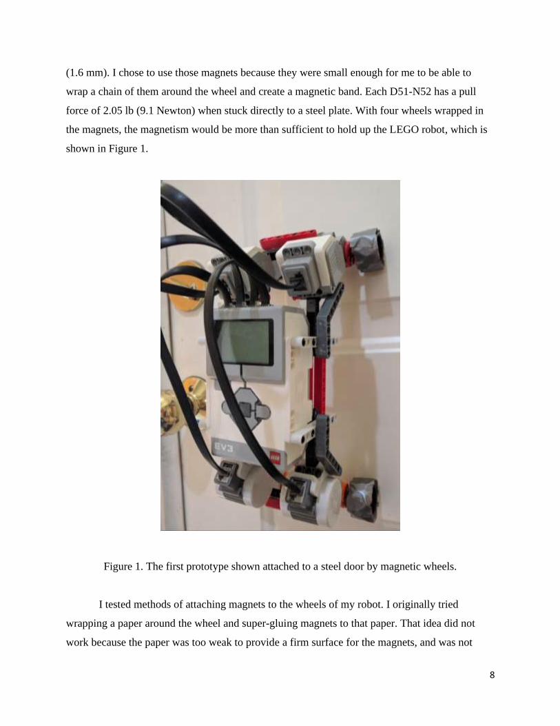
(1.6 mm). I chose to use those magnets because they were small enough for me to be able to
wrap a chain of them around the wheel and create a magnetic band. Each D51-N52 has a pull
force of 2.05 lb (9.1 Newton) when stuck directly to a steel plate. With four wheels wrapped in
the magnets, the magnetism would be more than sufficient to hold up the LEGO robot, which is
shown in Figure 1.
Figure 1. The first prototype shown attached to a steel door by magnetic wheels.
I tested methods of attaching magnets to the wheels of my robot. I originally tried
wrapping a paper around the wheel and super-gluing magnets to that paper. That idea did not
work because the paper was too weak to provide a firm surface for the magnets, and was not

9
strong enough to keep the magnets from clumping together and leaving the wheel. Next, I tried
filling the holes on the wheels with clay or playdoh, and attaching magnets over it. This idea also
failed because neither material would stick to superglue. After neither of the ideas worked, I
experimented to see if a hybrid of the two ideas would work. I filled the indentations in the
wheel with folded and compressed strips of paper. I then superglued the strips in place.
Afterwards, I wrapped paper that was folded and reinforced by thin strands of metal around the
wheel. The reinforced paper was a sturdy yet flexible enough surface for me to superglue
magnets. After attaching magnets successfully to all four wheels, I wrapped each wheel with
duct-tape instead of using a tire. The reason I chose not to use a tire was that a tire would reduce
the pull force of the magnets too much due to its thickness, while duct-tape would not
significantly reduce the pull force while still offering traction. After wrapping the wheels, I ran a
LEGO axle through each wheel and used it to attach each wheel to my motors.
The attachment of the wheels marked the end of the development of my first prototype. I
tested the prototype by pressing it to a steel door. The robot was able to stick tightly to the door
without slipping. The robot failed to meet several design constraints: It was larger than 25x25x25
cm, cost more than $200, was not tethered, required batteries, and did not support cameras.
However, this initial prototype met a key objective. The true objective of my first prototype was
to help me understand how to attach a robot to a ferrous surface efficiently with magnets, and
help me understand how to design a robot and wheels to solve the inspection problem.
4.2 Material and Component Selection for the Second Prototype
After building my first prototype robot with LEGOs, I decided to select components, and
design and visualize my next prototype on the computer before beginning construction. First, I
decided that I would use a Raspberry Pi as the core of my future prototypes. The reason I chose
the Raspberry Pi was that the Pi is a fairly powerful circuit board despite being very light and
compact. The Pi can connect to motor control boards, while still having USB and Ethernet
capabilities. In addition, the Pi is a very inexpensive computer and comes with a free OS
package. Figure 2 is a photograph of the Raspberry Pi 3.

10
Figure 2. The Raspberry Pi 3.
Next I decided to use the L298N motor control board to control my motors. The L298N
is a fairly simple motor controller that can control up 2 DC motors. The motor controller is
documented as being able to handle voltages of up to 35 V. Since most of the motors I wanted to
use were in the 6 V-12 V range, the L298N was ideal for me. The board itself is quite small, only
being a third the size of a Raspberry Pi. Because of this simplicity, it is easy to buy multiple
L298N’s at a low cost. I also decided that I would start out with a single camera for my first
prototype with the Raspberry Pi. The camera I chose to use is the Raspberry Pi NoIR camera.
This NoIR camera is a Pi compatible camera that is designed for night vision. While structures
like bridges may be lit, the interior of tanks will probably be dark; so I chose the Pi NoIR camera
instead of the standard Pi camera. I also chose the NoIR camera because it is built for the
Raspberry Pi and would be easier to use than any other camera.
For my motors, I chose standard 6 V DC plastic Arduino motors. I chose these motors
even though they were Arduino motors, because I knew that my driver board could run any DC
11
motor within its voltage limit. I did an engineering mechanics calculation, as discussed below, to
estimate the motor torque needed. The plastic motors are very easy to use and wire, and are also
inexpensive. If one of the motors broke, it would be easy to replace with a new motor. The
motors also come with plastic wheels that are large enough to support and move the robot, yet
small enough to be easily controlled. In addition to my two drive motors, I wanted to use another
motor to create a lever mechanism under the robot that could prop it up. The mechanism would
be used to lift the robot’s front end off the ground so that it could attach to a ferrous surface
better. I planned on mounting the robot on a simple plastic robot chassis, and using metal strips
to form an elevated platform for any part that could not be accomodated on the chassis itself. I
decided to power the L298Ns with a 4-AA battery pack or two 2-AA battery packs. The
Raspberry Pi was designed to receive power from a USB cable that extended to an electrical
outlet. The robot would be controlled by a wired Xbox 360 controller connected to it using a
USB cable. I decided to use an Xbox Controller because it has a directional pad, which would be
ideal for controlling the robot’s movement. It also has extra buttons which could be assigned to
different tasks within the robot’s code such as camera controls. For the magnets, I decided to
continue using D51-N52 magnets because I had proven that using them to create a magnetic
band around a wheel was a feasible method of creating a magnetic wheel with my first prototype.
4.3 Computer Aided Design (CAD) of the Second Prototype
After deciding on the materials and components I would use to make my 2nd prototype, I
moved on to constructing a CAD drawing of my prototype, so that I would be able to construct it
with ease once the parts I specified arrived. To make the CAD drawings, I used a software called
SketchUp, because the software was free, easy to learn on my own, and easy to use. Using online
and physical measurements (once the parts arrived) of the parts I planned to use to make my 2nd
prototype robot, I was able to construct a realistic 3D CAD drawing of my robot prototype as
shown in Figure 3. I then further refined my prototype taking optimal screw locations into
consideration. After a few iterations of adding design features and refining the details, I was able
to get a satisfactory 3D model of my robot. This served to simplify the hardware portion of my
project, as I just had to construct a physical copy of the computer model using real parts.
12
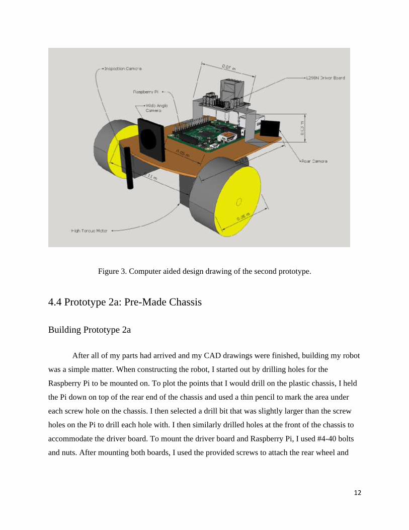
Figure 3. Computer aided design drawing of the second prototype.
4.4 Prototype 2a: Pre-Made Chassis
Building Prototype 2a
After all of my parts had arrived and my CAD drawings were finished, building my robot
was a simple matter. When constructing the robot, I started out by drilling holes for the
Raspberry Pi to be mounted on. To plot the points that I would drill on the plastic chassis, I held
the Pi down on top of the rear end of the chassis and used a thin pencil to mark the area under
each screw hole on the chassis. I then selected a drill bit that was slightly larger than the screw
holes on the Pi to drill each hole with. I then similarly drilled holes at the front of the chassis to
accommodate the driver board. To mount the driver board and Raspberry Pi, I used #4-40 bolts
and nuts. After mounting both boards, I used the provided screws to attach the rear wheel and
13
motors to pre-cut holes on the chassis. The chassis, motors, and rear wheel came together with
nuts, bolts and instructions, so attaching both components to the chassis was easy.
For this prototype, I used heavy duty double sided tape to attach a third motor to the
underside of the robot, directly in between both drive motors. I then took four popsicle sticks and
glued them together lengthwise in sets of two. As a result, I got two very thick popsicle sticks. I
then cut the popsicle sticks in half, and sketched the end of the motor axle on the end of each half
popsicle sticks. I then used a drill to carve out a hole in each of the new sticks that would
accommodate the motor axle. As a result, I got 4 thick, half-length, drilled popsicle sticks. I then
chose the two sticks that fit best, and attached them to each end of the axle on the middle motor.
I secured the popsicle sticks with hot glue. The purpose of this motorized contraption was to
serve as a lifter that would push the robot off the surface it was on once the motor was activated.
This device was designed to allow the robot to detach itself from a ferrous surface. It would also
enable the robot to elevate its main magnetic wheels off the ground so that it could attach itself to
a ferrous wall from another surface. This is one of several unique design features of this project.
The magnetic wheel design is another innovative feature.
After attaching the third motor, I used perforated metal hanger tape to create bridge-like
structures above the driver board and Raspberry Pi. The hanger tape served as a secondary
surface on which additional parts could be mounted. Because of the perforations, it was easy to
drill holes in the chassis to fit the metal hanger tape, and secure it with leftover bolts and nuts.
On top of the hanger tape bridge at the front of the robot, I attached a second driver board to
control the third motor since each board can only control two motors. I was able to attach the
driver board using double sided tape. With more double sided tape, I was able to attach a 4-AA
battery holder to the top of the rear metal hangar to power the main driver board. I also attached
two 2-AA battery holders to the front of my robot to power the second driver board.
I finished this second prototype by hot gluing the Raspberry Pi NoIR camera to the front
of metal hanger tape bridge. After building the robot, all that remained was to magnetize the
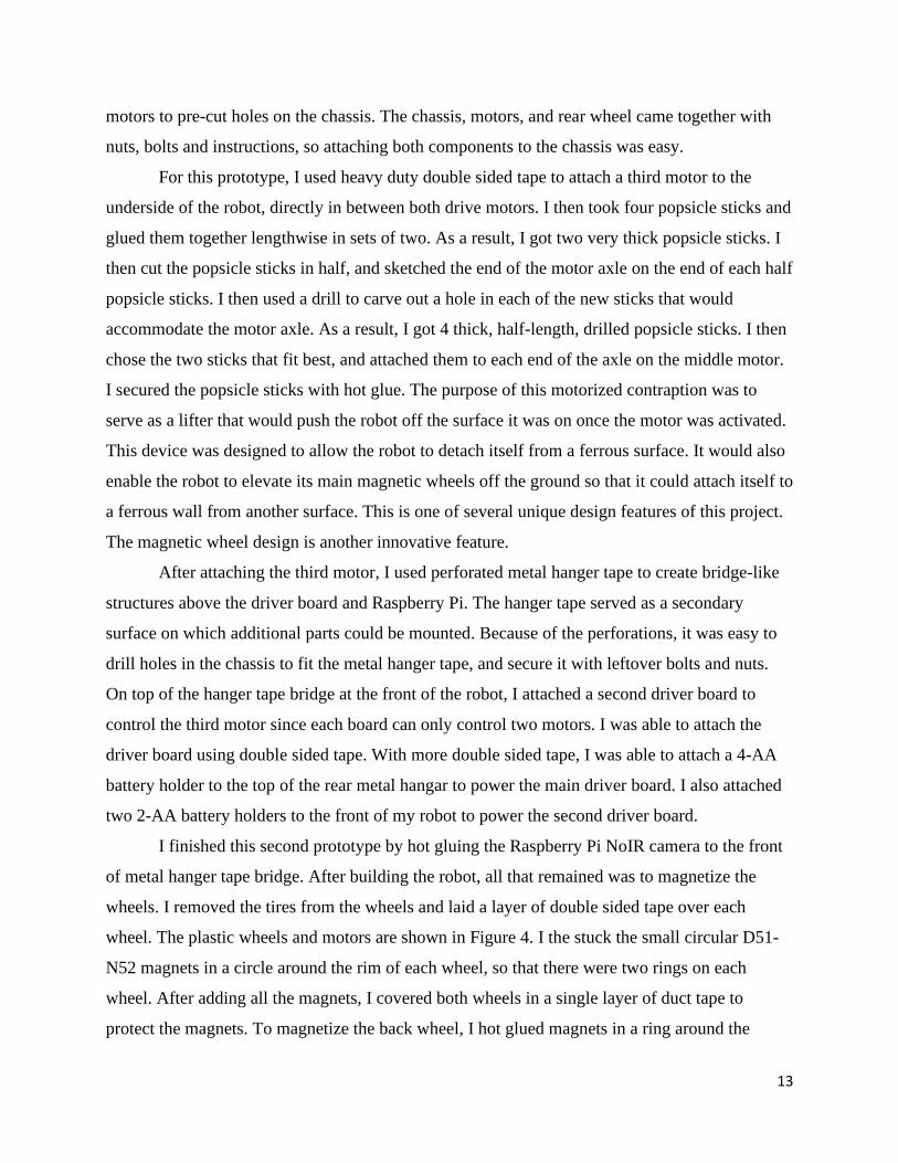
wheels. I removed the tires from the wheels and laid a layer of double sided tape over each
wheel. The plastic wheels and motors are shown in Figure 4. I the stuck the small circular D51-
N52 magnets in a circle around the rim of each wheel, so that there were two rings on each
wheel. After adding all the magnets, I covered both wheels in a single layer of duct tape to
protect the magnets. To magnetize the back wheel, I hot glued magnets in a ring around the
14
wheel and then wrapped them in duct tape. The reason duct tape was used was because it is thin
enough to not reduce the pull force significantly, but strong enough to protect the magnets.
Figure 4. Plastic wheels and motors for prototype 2a.
Wiring Prototype 2a
After attaching all of the components of my robot, I began wiring them together. The
power for the Raspberry Pi came in through the micro USB port on its side. I then wired the
battery packs to their respective driver boards. The motors were also connected to the driver
boards using wires that came with the motors. I soldered the wires to the power leads on the
motor and connected them with screws to the driver board. I then wired the GPIO pins on the Pi
to the driver boards. The GPIO pins are general purpose input/output pins on the Raspberry Pi.
Some pins are used for ground and power, while some can be used to send signals through a
wire. I wired GPIO 2 & 6 to one driver board and 4 & 9 to the other driver board. Those pins
were 5 V pins and were used to enable motor movement and control through the driver boards. I
then wired pin 11, 12, 13, & 15 to the first driver board, and wired pins 16, & 18 to the other
driver board. Those pins were used for sending the actual motor control signal. Each motor

15
required two pins for control, and since the robot used 3 motors the driver boards required 6
connected signal GPIO pins for motor control, in addition to a 5V and ground per board. After I
connected the necessary GPIO pins, I connected an Ethernet cable between my Pi and my laptop,
so that my laptop would be able to have a remote desktop connection with my Raspberry Pi,
eliminating the need for a monitor, keyboard, and mouse. I also connected a powered hub via
USB to my Pi. The hub was connected to an Xbox controller, so that I would be able to control
the robot through the Xbox controller.
Programming Prototype 2a
The hardest part about designing my 2nd prototype was the code. With my first prototype,
it was merely a hardware model; it ran no code. My reason being, with my 1st prototype, try as I
might, I was unable to get all 4 motors to move simultaneously with code. The first prototype
was also created mainly to test the magnetic wheel concept and to help me come up with an ideal
design for future prototypes. On the Raspberry Pi, I coded with Python, because it was the only
language for the Raspberry Pi that I understood. But even before I started on my code, I had to
set up my robot to be remote desktop compatible with my laptop.
To set up my Pi, I had to temporarily attach a monitor, keyboard, and mouse to the
Raspberry Pi. Afterwards, I booted up the Pi and set a static IP for it over Ethernet. I chose
192.168.1.10 because it was a simple and easy address. To set the IP I had to edit
/ect/dhcpcd.conf in my Pi. The dhpcd.conf file controls the IP and network connection of the Pi;
to set a static IP I had to add the lines to the beginning of the file:
interface eth0
static ip_address=192.168.1.10
static routers=192.168.1.1
After setting the static IP of the Pi, I installed the Linux package tightvncserver. Tightvncserver
is a package that allows for a VNC (virtual network connection) server to be set up on the
Raspberry Pi. Remote Desktop connections are run through VNC servers. After setting up the
VNC server, I was able to create a Remote Desktop connection to my Raspberry Pi through my
16
laptop. After confirming that I could access my Pi, I disconnected my monitor, keyboard, and
mouse. I then began the coding for the robot.
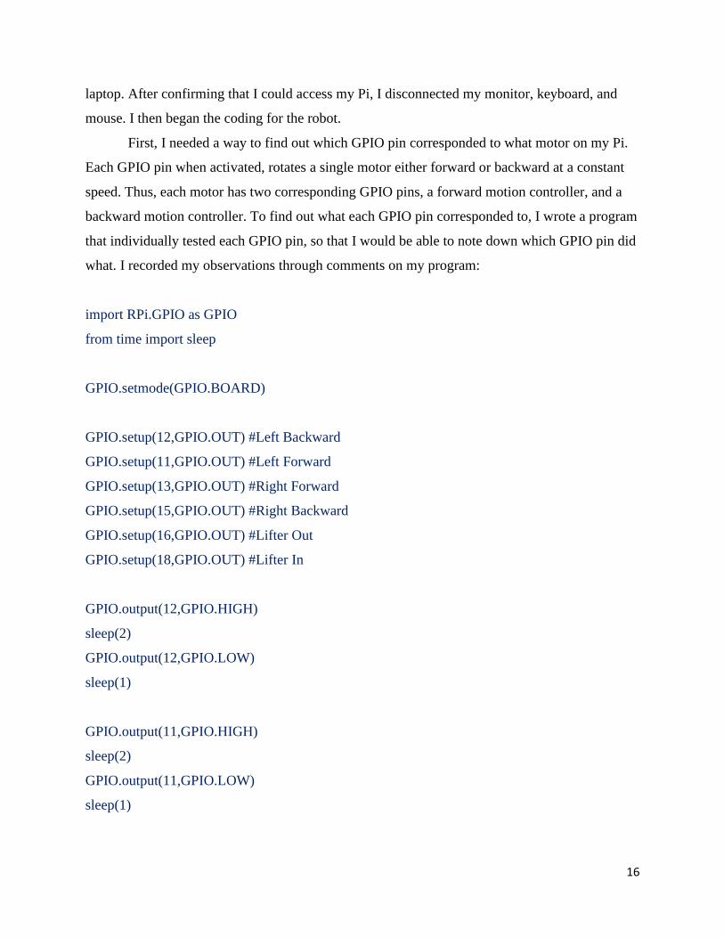
First, I needed a way to find out which GPIO pin corresponded to what motor on my Pi.
Each GPIO pin when activated, rotates a single motor either forward or backward at a constant
speed. Thus, each motor has two corresponding GPIO pins, a forward motion controller, and a
backward motion controller. To find out what each GPIO pin corresponded to, I wrote a program
that individually tested each GPIO pin, so that I would be able to note down which GPIO pin did
what. I recorded my observations through comments on my program:
import RPi.GPIO as GPIO
from time import sleep
GPIO.setmode(GPIO.BOARD)
GPIO.setup(12,GPIO.OUT) #Left Backward
GPIO.setup(11,GPIO.OUT) #Left Forward
GPIO.setup(13,GPIO.OUT) #Right Forward
GPIO.setup(15,GPIO.OUT) #Right Backward
GPIO.setup(16,GPIO.OUT) #Lifter Out
GPIO.setup(18,GPIO.OUT) #Lifter In
GPIO.output(12,GPIO.HIGH)
sleep(2)
GPIO.output(12,GPIO.LOW)
sleep(1)
GPIO.output(11,GPIO.HIGH)
sleep(2)
GPIO.output(11,GPIO.LOW)
sleep(1)
17
GPIO.output(13,GPIO.HIGH)
sleep(2)
GPIO.output(13,GPIO.LOW)
sleep(1)
GPIO.output(15,GPIO.HIGH)
sleep(2)
GPIO.output(15,GPIO.LOW)
sleep(1)
GPIO.output(16,GPIO.HIGH)
sleep(0.5)
GPIO.output(16,GPIO.LOW)
sleep(1)
GPIO.output(18,GPIO.HIGH)
sleep(0.5)
GPIO.output(18,GPIO.LOW)
sleep(1)
Next, I needed software or code that would enable my Raspberry Pi to receive and understand
signals sent to it by the Xbox controller. Xboxdrv is an Xbox controller driver for Linux. I
installed it and used it to try to connect my Pi to my Xbox controller. Normally running the
command ‘sudo xboxdrv’ in the prompt will display the inputs of connected Xbox controller in
the command prompt window. My Xbox controller however, was not made by Microsoft, so it
was not supported normally by xboxdrv I fixed the problem by running the command:
sudo xboxdrv --device-by-id 1bad:f02e --type xbox360 --detach-kernel-driver --mimic-xpad
I was able to create this command after researching how to use xboxdrv and how to modify the
normal function with code. With this command, I identified the connected controller as an Xbox
controller using its device id which was 1bad:f02e. This command allowed me to view the inputs
from the controller in the command prompt. I needed a way to access the input values from a
18
Python program, so that I would be able to use the values to control my robot. After some
searching online, I found a Python program that received and displayed Xbox controller input
values on Github7. The code was by martinohanlon. I downloaded the code onto my Raspberry
Pi and started working on modifying it to control the motors on the robot based on the values it
received. The problem I faced was that the code was so long and complex, that I was unable to
tell where the input value from the Xbox controller was read. To solve that problem, I went
through the program and I made a series of print statements that printed the variables of the
program as it ran. Through the process of observing the values as buttons were pressed, and
deleting print statements, I was able to find the main event system in the program at line 265:
#run until the controller is stopped
while(self.running):
#react to the pygame events that come from the xbox controller
for event in pygame.event.get():
#thumb sticks, trigger buttons
if event.type == JOYAXISMOTION:
#is this axis on our xbox controller
if event.axis in self.AXISCONTROLMAP:
#is this a y axis
yAxis = True if (event.axis == self.PyGameAxis.LTHUMBY or event.axis ==
self.PyGameAxis.RTHUMBY) else False
#update the control value
self.updateControlValue(self.AXISCONTROLMAP[event.axis],
self._sortOutAxisValue(event.value, yAxis))
#is this axis a trigger
if event.axis in self.TRIGGERCONTROLMAP:
#update the control value
self.updateControlValue(self.TRIGGERCONTROLMAP[event.axis],
self._sortOutTriggerValue(event.value))
7 https://github.com/martinohanlon/XboxController/blob/master/XboxController.py
19
#d pad
elif event.type == JOYHATMOTION:
#update control value
self.updateControlValue(self.XboxControls.DPAD, event.value)
#button pressed and unpressed
elif event.type == JOYBUTTONUP or event.type == JOYBUTTONDOWN:
#is this button on our xbox controller
if event.button in self.BUTTONCONTROLMAP:
#update control value
self.updateControlValue(self.BUTTONCONTROLMAP[event.button],
self._sortOutButtonValue(event.type))
Within the main event system, I searched for the component that handled the directional pad (d-
pad) on the Xbox controller, as I was planning on using it to control the motors on the robot.
After finding the directional pad control component, I added some statements to the end that sent
signals through the GPIO pins to the motors whenever a certain direction was pressed on the D-
Pad:
#d pad
elif event.type == JOYHATMOTION:
#update control value
self.updateControlValue(self.XboxControls.DPAD, event.value)
if event.value == (0,1): #Forward
GPIO.output(11,GPIO.HIGH) #Left Forward
GPIO.output(13,GPIO.HIGH) #Right Forward
elif event.value == (0,-1): #Backward
GPIO.output(12,GPIO.HIGH) #Left Backward
GPIO.output(15,GPIO.HIGH) #Right Backward
elif event.value == (1,0): #Right
GPIO.output(11,GPIO.HIGH) #Left Forward
20
GPIO.output(15,GPIO.HIGH) #Right Backward
elif event.value == (0,1): #Left
GPIO.output(12,GPIO.HIGH) #Left Backward
GPIO.output(13,GPIO.HIGH) #Right Forward
GPIO.output(12,GPIO.LOW)
GPIO.output(11,GPIO.LOW)
GPIO.output(13,GPIO.LOW)
GPIO.output(15,GPIO.LOW)
After successfully configuring the motors, my next challenge was to code the Raspberry NoIR
camera. The Pi camera came with a Python camera package. Coding it so that pictures were
taken or videos were recorded every time certain buttons on the Xbox controller were pressed
was fairly easy.
#button pressed and unpressed
elif event.type == JOYBUTTONUP or event.type == JOYBUTTONDOWN:
#is this button on our xbox controller
if event.button in self.BUTTONCONTROLMAP:
#update control value
self.updateControlValue(self.BUTTONCONTROLMAP[event.button],
self._sortOutButtonValue(event.type))
if event.button == 0 and event.type == 10:
camera.capture('image' + imgNum + '.jpg')
imgNum = imgNum + 1
if event.button == 1 and event.type == 10:
if isRec == False:
camera.start_recording('video' + recNum + '.h264')
isRec = True
else:
21
camera.stop_recording()
isRec = False
if event.button == 1 and event.type == 10:
if isPrev == False:
camera.start_preview()
isPrev == True
else:
camera.stop_preview()
isPrev == False
For this portion of the code, I did have to make variables to serve as counters every time a
picture or video was taken, so that they would be numbered. I also had to make Boolean
variables that determined whether a video was being taken, to prevent the robot from trying to
take another video while one was already recording. After coding the camera, I was finished with
programming the robot.
Testing Prototype 2a
The first thing I recorded was the mass of the robot. Using a standard kitchen scale, I
recorded the mass of the robot to be 0.66 kg. While not being especially light, prototype 2a was
significantly lighter than prototype 1, which had a mass of 0.92 kg without cameras. Prototype 2a
was also measured to be 15 cm long x 18 cm wide x 12 cm tall. Prototype 2a could meet the size
constraint, which was another improvement over prototype 1. Prototype 2a could stick to ferrous
surfaces. While the motor of prototype 1 could not overcome the magnetic pull force and move
the robot, prototype 2 could move the robot downward or sideways but not upward when
attached to a vertical steel wall. The 3rd motor on the robot that was planned for lifting of off
surfaces was also unable to function because of a lack of torque. Prototype 2a had only mounted
1 camera, and thus failed the multiple camera requirement. However, prototype 2a was an
improvement over prototype 1. Prototype 2a only cost about $120 to build compared to
prototype 1, which cost more than $400 even without cameras.
22
4.5 Engineering Mechanics Calculations
I calculated force and torque using equations from the literature as shown below.
Force and Torque Equations
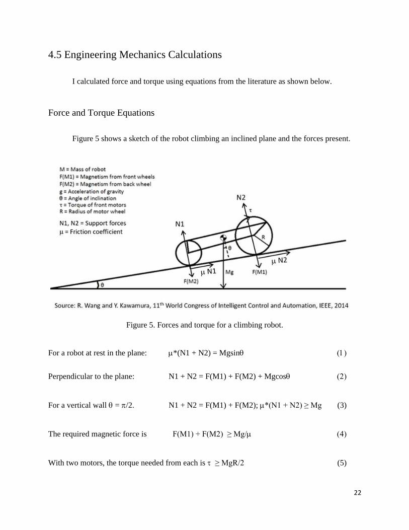
Figure 5 shows a sketch of the robot climbing an inclined plane and the forces present.
Figure 5. Forces and torque for a climbing robot.
For a robot at rest in the plane: *(N1 + N2) = Mgsin ()
Perpendicular to the plane: N1 + N2 = F(M1) + F(M2) + Mgcos ()
For a vertical wall = /2. N1 + N2 = F(M1) + F(M2); *(N1 + N2) ≥ Mg (3)
The required magnetic force is F(M1) + F(M2) ≥ Mg/ ()
With two motors, the torque needed from each is ≥ MgR/2 (5)

23
Force Calculation for Magnet Placement
The paper by Wang and Kimura (IEEE 2014) shows that the friction coefficient for tape
covered wheel on metal = 0.45. The mass of my robot prototype 2a is M = 0.655 kg. The
acceleration of gravity g = 9.81 m/s2. From equation (4), the required magnetic force = 14.5
Newton. The pull force of the N52 magnet away from a steel surface has been tested and
reported by the manufacturer KJ Magnetics. It is shown for different distances in Figure 6. The
thickness of the duct tape I used is 0.01”. At a distance of 0.01”, the pull force is 1.26 lb per
magnet according to the data plotted in Figure 6. In SI units, this pull force per magnet = 5.6
Newton. To get a magnetic force of at least 14.5 Newtons calculated from equation (4), we need
at least 3 magnets in contact at all times (one per wheel). The value of 0.45 is only an
estimate. If it is lower (say 0.25), the required magnetic force is higher, about 26.1 Newton.
Thus, for safety, we need 2 rows of magnets per wheel.
Figure 6. Pull force of a N52 NdFeB magnet away from a steel surface.
24
Torque Calculation for Motor Selection
Torque is important, because it is the rotational force (force multiplied by radial distance)
that the motor must generate to move the robot. From equation (6), we know that the torque
must be greater than MgR/2 for each of the front wheel motors. For prototype 2a, this works to
torque being more than 0.08 Newton meter per motor. The plastic encased motors I used in the
prototype 2a (Figure 4) were rated by the manufacturer as 0.1 Newton meter each. In my tests,
prototype #2a could stay attached to a vertical surface and climb down. However, it struggled to
climb up the vertical wall. The torque was barely enough to fight gravity. The results of this test
of prototype #2a show that the force and torque calculations were correct. The lesson I learned
from building and testing prototype 2a is that the robot should be lighter or a motor with greater
torque should be used. The use of CAD and mechanics calculations made the design and
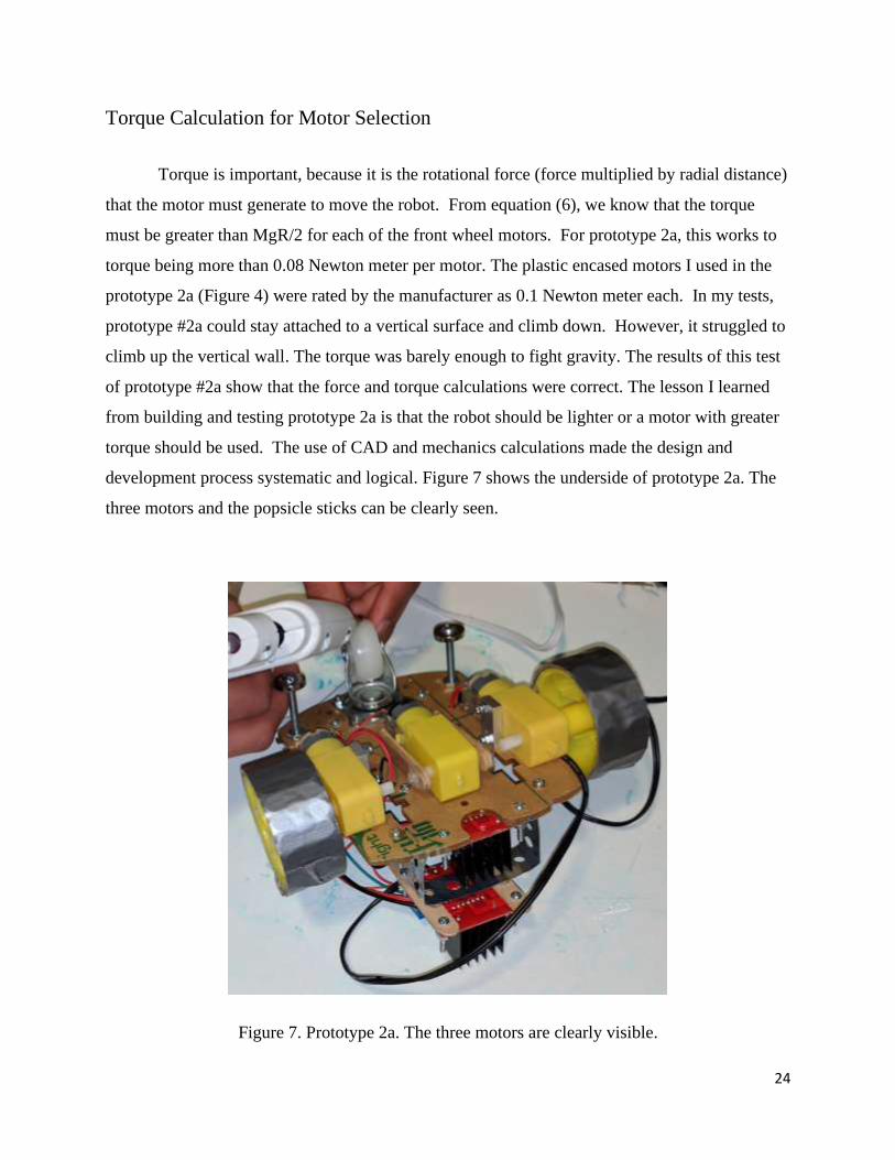
development process systematic and logical. Figure 7 shows the underside of prototype 2a. The
three motors and the popsicle sticks can be clearly seen.
Figure 7. Prototype 2a. The three motors are clearly visible.

25
4.6 Prototype 2b: Pre-Made Chassis
After developing and testing Prototype 2a, I realized that there were multiple changes I
could make to it to make it fit the constraints better, without constructing an entirely new bot. So
instead of starting from scratch, I decided to make a series of modifications and upgrades to
Prototype 2a, resulting in the creation of Prototype 2b.
Building Prototype 2b
The first change I made to prototype 2a was that I removed all the motors. The motors
did not work as expected for climbing up a vertical wall because of lack of torque; so, all of them
had to be replaced or removed. I replaced the drive motors with two new larger motors, and I
simply removed the third motor without replacement. The new motors were Uxcell 12V high
torque gearbox motors. They were chosen, because their torque rating was much higher than that
of the motors they replaced, but these new motors were heavier. I fastened both motors to the
underside of the robot, where the previous motors had been using strips of double sided tape for
preliminary testing. The new motors had a mass almost 100 g more than that of the old motors
and so adding both new motors added almost 200 g to the mass of the robot.
I removed the driver board that controlled the third motor, because there was no longer a
third motor on the robot, so there was only a need for a single driver board. Next, I removed all
of the battery packs on the robot. Battery packs add unnecessary mass to a robot, and only limit
its inspection life. Additionally, using batteries increases chances of motor failure when the robot
is in deployment, because batteries might run out of battery power in the middle of a run,
resulting in the need for an emergency retrieval. I then moved the remaining driver board onto
the metal hanger above the Raspberry Pi, where the 4-AA battery pack had been previously. This
allowed me to remove the metal hanger at the front of the robot because it was not being used. I
also removed two posts with magnetic disks at the rear of the robot that were included in
Prototype 2a to increase the stability of the rear. I found out through testing that the posts were
not needed.
At this stage, I encountered a major problem. My wheels were no longer compatible with
my motors because the new motors had a different shaft compared to the old motors. I tried

26
drilling and cutting the wheel wells to make the wheels fit the motors, but neither solution
worked. After some research on what items fit a D shaped motor shaft, I found out that oven
knobs often fit D shafts. After buying some oven knobs, I tested them to see if they attach to the
motors. After finding out the oven knobs were compatible with the new motors, I sawed the top
off the oven knobs, resulting in flat disks that fit onto the new motors. I then drilled out the
wheel well on the wheels, after which I superglued the disks to the wheels. By supergluing the
disks to the wheels, I made it so that they would be able to attach to the motor. After attaching
the wheels and motors, I set up the cameras. I hot glued the Pi NoIR camera to the back of the
robot and made it face backwards for my rear-view camera. I then took a wide-angle, fish-eye
camera, and hot glued it to the front of my robot facing forwards for my main camera. I then
double sided taped and hot glued an endoscopic inspection camera to the front rim of the chassis
facing downwards. The use of oven knobs to connect wheels to the new motor shaft is an
innovative solution developed in this project.
Wiring Prototype 2b
After modifying prototype 2a, there were many components to re-wire. I had to re-solder
a wire to the power leads of the motors and connect it to the remaining driver board. I then
removed all of the wires connected to GPIO 4, 9, 16, or 18, as they were no longer in use. I also
decided to use a 12 V power cable to power the driver board instead of a battery pack. To do so,
I cut the output end of the power cable off, so that all that remained was the adapter and a length
of wire. I then separated the two strands of power wire, one being positive and the other being
negative, and stripped the wires so that both wires were exposed at the end. After twisting and
tightening the exposed wire, I connected the positive wire to the ground slot on the driver board,
and the negative wire into the voltage slot on the driver board. I left the NoIR camera connected
to the Pi, but I connected both the other cameras to my laptop so that my laptop directly received
feeds directly from the cameras instead of getting them through the Pi, with the exception of the
NoIR camera. To finish, I swapped the Xbox Controller with a Super Nintendo Entertainment
System (SNES ) controller. An SNES controller is a much lighter and simpler controller than an
Xbox controller and unlike the Xbox controller which requires a powered hub for power, an
27
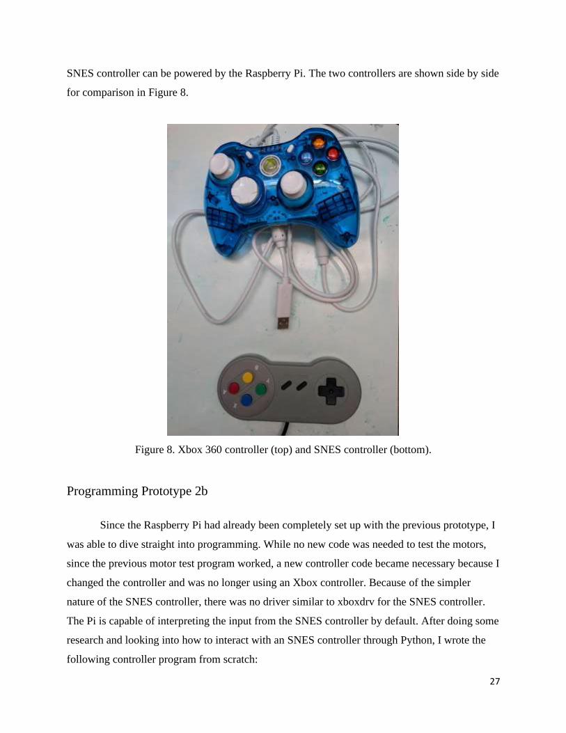
SNES controller can be powered by the Raspberry Pi. The two controllers are shown side by side
for comparison in Figure 8.
Figure 8. Xbox 360 controller (top) and SNES controller (bottom).
Programming Prototype 2b
Since the Raspberry Pi had already been completely set up with the previous prototype, I
was able to dive straight into programming. While no new code was needed to test the motors,
since the previous motor test program worked, a new controller code became necessary because I
changed the controller and was no longer using an Xbox controller. Because of the simpler
nature of the SNES controller, there was no driver similar to xboxdrv for the SNES controller.
The Pi is capable of interpreting the input from the SNES controller by default. After doing some
research and looking into how to interact with an SNES controller through Python, I wrote the
following controller program from scratch:
28
import pygame
import RPi.GPIO as GPIO
GPIO.setmode(GPIO.BOARD)
GPIO.setup(12,GPIO.OUT) #Left Backward
GPIO.setup(11,GPIO.OUT) #Left Forward
GPIO.setup(13,GPIO.OUT) #Right Forward
GPIO.setup(15,GPIO.OUT) #Right Backward
global hadEvent
global x
global y
global a
global b
global up
global down
global left
global right
hadEvent = False
x = False
y = False
a = False
b = False
up = False
down = False
left = False
right = False
pygame.init()

29
pygame.joystick.init()
j = pygame.joystick.Joystick(0)
j.init()
def game_controller(events):
global hadEvent
global x
global y
global a
global b
global up
global down
global left
global right
for event in events:
if event.type == pygame.JOYBUTTONDOWN:
hadEvent = True
x = j.get_button(0)
y = j.get_button(3)
a = j.get_button(1)
b = j.get_button(2)
if x == 1:
x = True
print("x")
elif y == 1:
y = True
print("y")
elif a == 1:

30
a = True
print("a")
elif b == 1:
b = True
print("b")
elif up == 1:
up = True
print("up")
elif event.type == pygame.JOYBUTTONUP:
hadEvent = False
x = j.get_button(0)
y = j.get_button(3)
a = j.get_button(1)
b = j.get_button(2)
if x == 1:
x = False
elif y == 1:
y = False
elif a == 1:
a = False
elif b == 1:
b = False
elif up == 1:
up = False
elif event.type == pygame.JOYAXISMOTION:
hadEvent = True
if event.axis == 1:
if event.value <= -1:
31
up = True
print("up")
elif event.value >= 1:
down = True
print("down")
else:
down = False
up = False
elif event.axis == 0:
if event.value <= -1:
left = True
print("left")
elif event.value >= 1:
right = True
print("right")
else:
right = False
left = False
while True:
game_controller(pygame.event.get())
if up == True: #Forward
GPIO.output(11,GPIO.HIGH) #Left Forward
GPIO.output(13,GPIO.HIGH) #Right Forward
elif down == True: #Backward
GPIO.output(12,GPIO.HIGH) #Left Backward
GPIO.output(15,GPIO.HIGH) #Right Backward
elif right == True: #Right
GPIO.output(11,GPIO.HIGH) #Left Forward
GPIO.output(15,GPIO.HIGH) #Right Backward

32
elif left == True: #Left
GPIO.output(12,GPIO.HIGH) #Left Backward
GPIO.output(13,GPIO.HIGH) #Right Forward
else:
GPIO.output(12,GPIO.LOW)
GPIO.output(11,GPIO.LOW)
GPIO.output(13,GPIO.LOW)
GPIO.output(15,GPIO.LOW)
This code operates by importing Pygame, which is a Python package. Pygame is used for
constructing videogames through Python. It adds several features, such as interpreting and
translating input values from a video game controller. Because of the simplicity of an SNES
controller, there were no extra steps needed. Towards the beginning of the program, I defined the
GPIO pins to be used for motor control. I then listed variables I planned to use, and assigned the
connected controller to pygame.joystick() and then j. I then created an event system where a
value sent by the controller is defined as an event, for example, pressing a button or moving a
joystick. I then specified the events I care about, such as movement on the directional pad (d-
pad) or a button being pressed. I assigned a value of 1 to a variable if the event it is connected to
occured. I also wrote additional code to convert the numeric value 1 to the Boolean True. At the
end, there is an infinite loop that fetches the values of events that were triggered. If any of the d-
pad values are triggered, the program sends signals to the motors through the GPIO pins. After
running this code, the robot responded smoothly to the SNES controller. I did not need any other
code for controlling this prototype.
Testing Prototype 2b
Once again, I started by recording the mass of the robot. Using a standard kitchen scale, I
recorded the mass of the robot to be 0.71 kg. Prototype 2b ended up being heavier than prototype
2a, despite the removal of the battery packs, but this can be attributed to the motors which were
heavier in prototype 2b. Prototype 2b was measured to be 15 cm long x 18 cm wide x 12 cm tall.
Prototype 2a and 2b are the same size despite the changes between the two, the overall structure
33
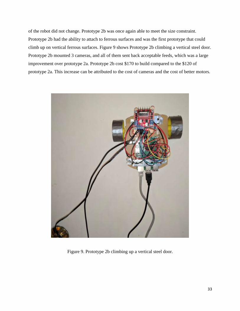
of the robot did not change. Prototype 2b was once again able to meet the size constraint.
Prototype 2b had the ability to attach to ferrous surfaces and was the first prototype that could
climb up on vertical ferrous surfaces. Figure 9 shows Prototype 2b climbing a vertical steel door.
Prototype 2b mounted 3 cameras, and all of them sent back acceptable feeds, which was a large
improvement over prototype 2a. Prototype 2b cost $170 to build compared to the $120 of
prototype 2a. This increase can be attributed to the cost of cameras and the cost of better motors.
Figure 9. Prototype 2b climbing up a vertical steel door.

34
4.7 Prototype 3: Custom Polycarbonate Chassis
After building the last two prototypes, I wanted to apply the knowledge I had gained to
create a new prototype that was smaller, more compact, and more efficient. To do this, I planned
to design my own chassis, and refrain from using tapes and superglue to hold parts together.
Building Prototype 3
To start building my robot, I took a polycarbonate sheet and cut my chassis out of it. For
my chassis, I chose a simple 6 cm wide x 11 cm long rectangle. I chose that size and shape
because it was simple and based off of preliminary measurements I took, it was the smallest
feasible size for mounting the parts I had chosen. After cutting out the chassis with a saw, I
smoothed out the edges and corners with a file and sandpaper. I then set the Raspberry Pi on the
rear end of the chassis and marked where all of the holes were, so that I would be able to drill
them out. I then set the rear wheel on the underside of the chassis and marked holes for it. I also
marked holes for the motors I chose at the front of the chassis. The motors I chose were Pololu
12 V gearbox motors with a gear ratio of 298:1. The motors also came with mounting brackets
that attached to the motors and had holes for screws. I finally marked a large hole between the Pi
and the motors for the inspection camera.
After drilling all of the holes, I screwed down all of the parts except for the Pi. Before I
screwed down the Pi, I laid down a thin sheet (4 mm thick) of packing foam underneath where
the Pi would be to absorb shock and prevent contact between the metal on the Pi and the bolts
and nuts on the robot. I also attached a folded metal hanger tape with the same bolts as the Pi.
The hanger tape formed a bridge over the Pi. I cut a smaller 4.5 cm wide x 5.5 cm long piece of
polycarbonate to screw to the top of the metal hangar. I screwed a driver board to the top of the
smaller polycarbonate. For the wide-angle camera, I folded and cut thin scrap metal to form a
pouch for the camera with a hole for the lens. The pouch had sides that folded in and held the
camera. The pouch also had a flat bottom that extended out to either side. I screwed the metal
pouch down with two of the screws that also held the motors. I slid the inspection camera down
into the hole that had been drilled for it. The Pi NoIR camera was held by a retaining block that
was hot glued to the top of the Ethernet port on the Pi. For the wheels, I used 60 mm diameter x
35
8 mm thick Pololu plastic wheels. To magnetize the wheel, I covered it in a thin layer of double
sided tape and put the magnets in a ring around it. I the covered the magnets with a single layer
of duct-tape for protection and traction. After finishing the wheels, I attached a 3V LED light on
either side of the wide-angle camera holder. I also used double sided tape to attach an ultrasonic
sensor to the bottom of the robot.
The robot utilizes an HC-SR04 ultrasonic distance sensor. The HC-SR04 is a very
common and popular hobby ultrasonic distance sensor. The sensor is also the least expensive and
easiest to use of its type to demonstrate sensor integration. The HC-SR04 is designed mainly
with compatibility and simplicity in mind, allowing it to be easily connected to a Raspberry Pi or
Arduino.
The HC-SR04 functions by sending a sound wave, which bounces off the object at which
the sensor points, and then receiving the sound wave. The time between the sending and the
reception of the sound wave is recorded and output. The time can then be multiplied by the speed
of sound and divided by 2 to identify the distance between the sensor and the surface it is pointed
towards. The HC-SR04 has 4 pins for connection purposes. The pins are ground, voltage, trigger,
and echo. The ground pin is to be connected to ground. The voltage pin is to be connected to a
+5V source. The trigger pin will cause the sensor to produce a sound wave for as long as it is
receiving +3V. The echo pin sends back +5V in a burst as long as the wait time for the sensor to
receive the signal. The sensor has a range of 2 cm to 400 cm. On my robot, the HC-SR04 serves
to demonstrate that an ultrasonic sensor can be mounted underneath the robot. A more expensive,
advanced ultrasonic sensor can be mounted to measure the thickness of the metal surface and
identify degradation.
Wiring Prototype 3
For the wiring of prototype 3, many elements stayed the same from prototype 2b but one
changed. Because the Pololu wheels blocked the micro USB port on the Pi, I was unable to use it
for power. After some research, I found that I could use the GPIO pins instead. I cut a USB to
micro USB cable so that one portion was the USB end and a length of cable. Within the cable
were two separate wires. I split and stripped those wired. I then soldered the exposed parts of the
wires to the female end of a breadboard jumper. I covered my work with heat shrink tubing. I
36
used a multimeter to tell which end was positive voltage and which end was negative. I
connected the positive wire to GPIO 9, and the negative end to GPIO 14. Those two GPIO’s
were 5 V & ground respectively. After connecting the USB end of the charging cable to a 5 V
adapter, the Pi ran perfectly. Once again, wires were soldered to the leads of my motors, and
connected back to my driver board. The driver board was connected to GPIO 11, 12, 13, & 15
for control and GPIO 2 & 6 for 5V and ground. The driver board was also connected to a 12 V
power supply. The LED lights were wired and soldered in parallel. They were attached a 330Ω
resistor, GPIO 16 & 18 for power, and GPIO 9 for ground. The ultrasonic sensor which was
added to this prototype was wired to GPIO 4, 29, 30, and 31. Pin 4 was used for voltage, 29
was for output, 31 was for input, and 30 was for ground. The NoIR camera was once again
connected to the Pi, while the other cameras are connected to my laptop. The robot is still
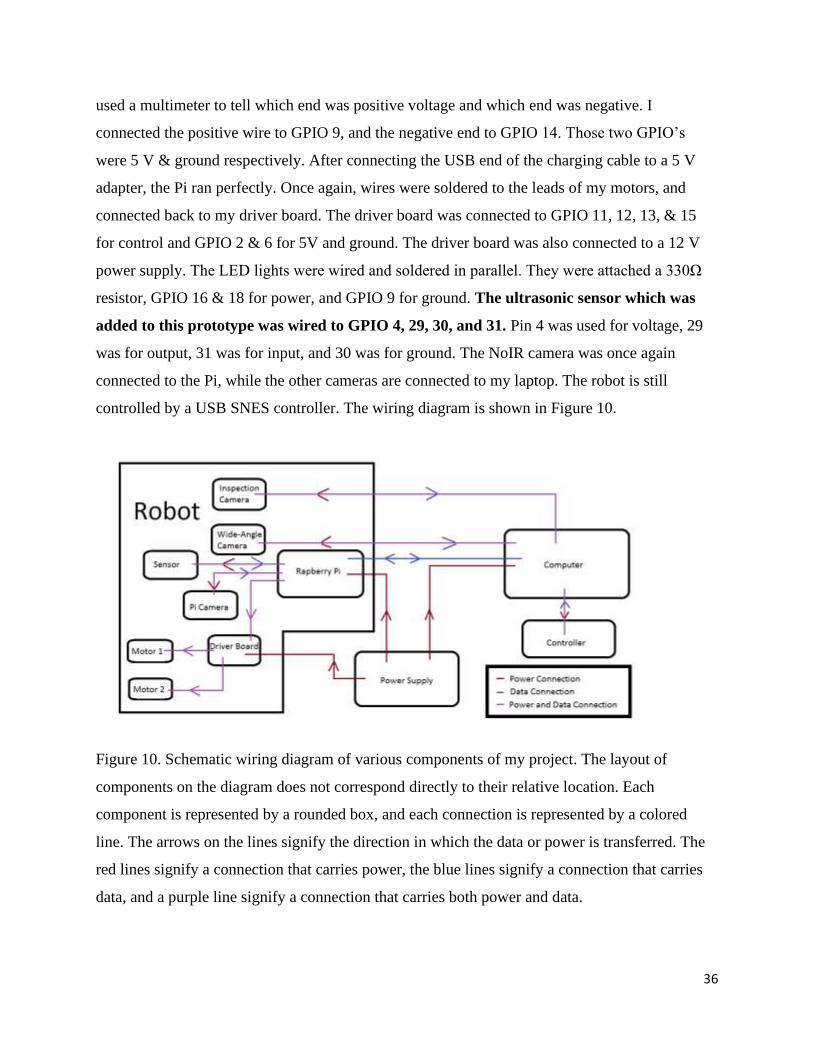
controlled by a USB SNES controller. The wiring diagram is shown in Figure 10.
Figure 10. Schematic wiring diagram of various components of my project. The layout of
components on the diagram does not correspond directly to their relative location. Each
component is represented by a rounded box, and each connection is represented by a colored
line. The arrows on the lines signify the direction in which the data or power is transferred. The
red lines signify a connection that carries power, the blue lines signify a connection that carries
data, and a purple line signify a connection that carries both power and data.
37
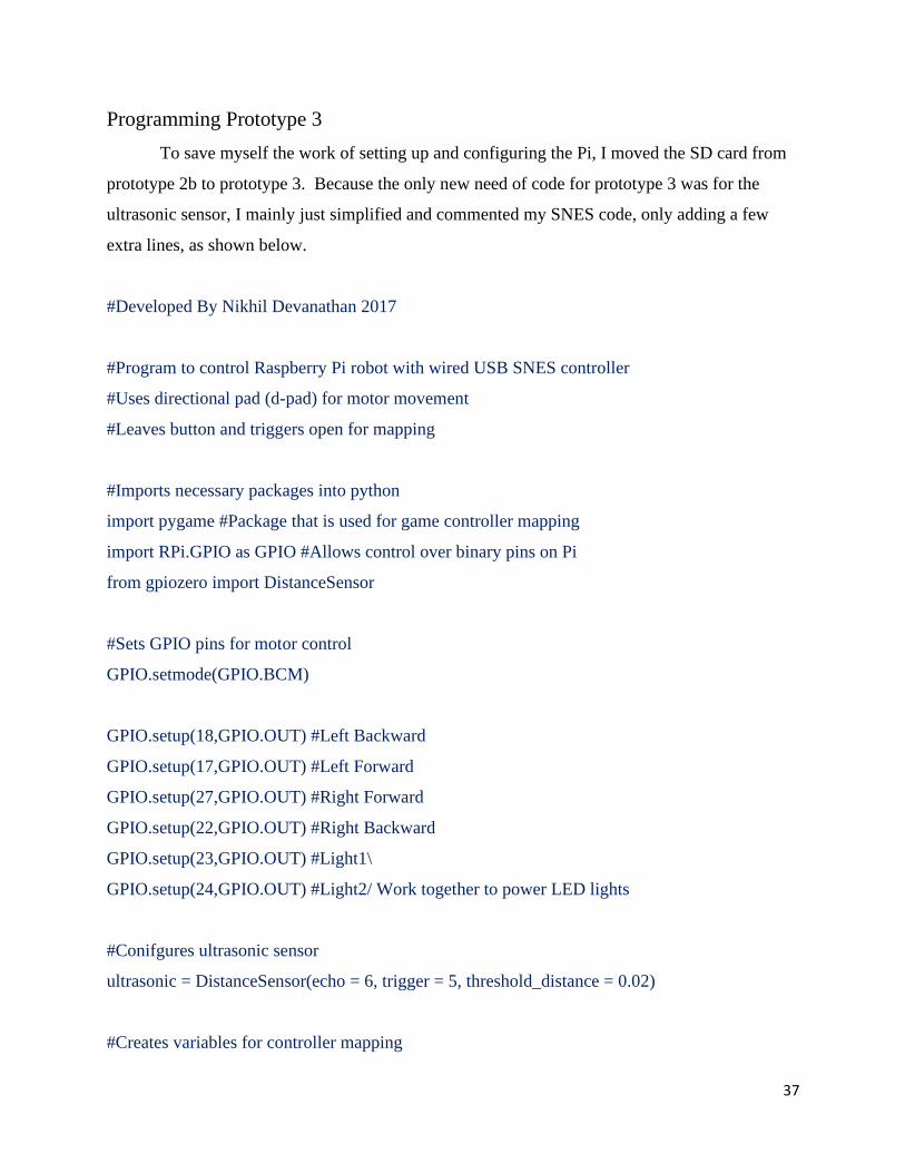
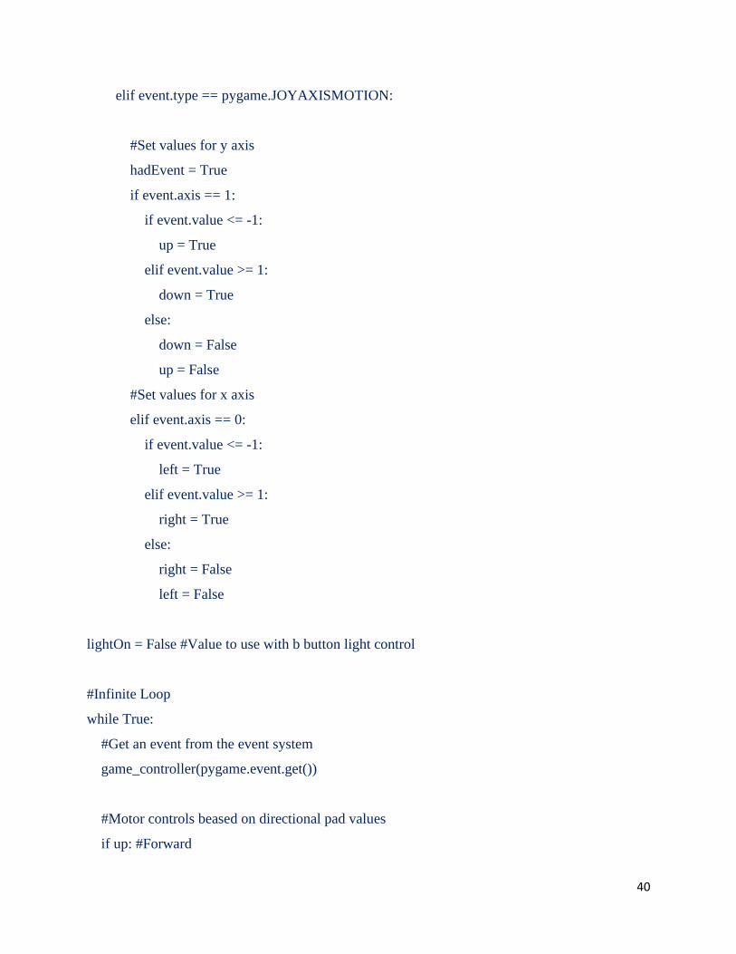
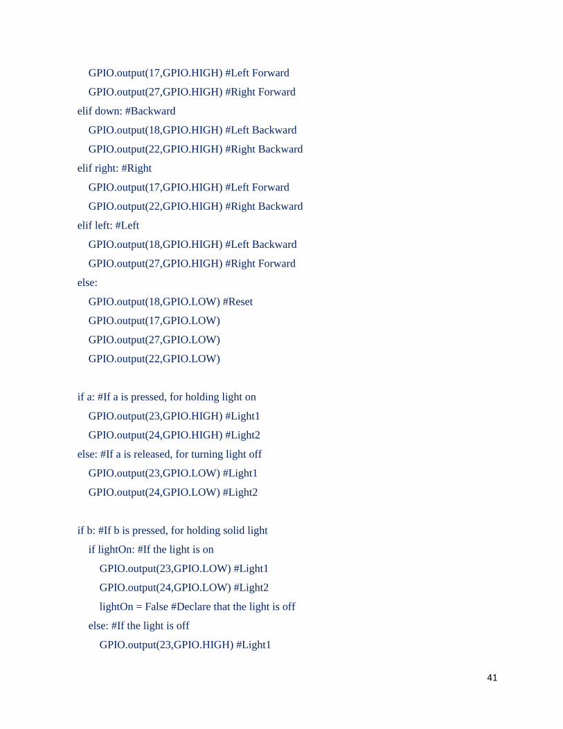
Programming Prototype 3
To save myself the work of setting up and configuring the Pi, I moved the SD card from
prototype 2b to prototype 3. Because the only new need of code for prototype 3 was for the
ultrasonic sensor, I mainly just simplified and commented my SNES code, only adding a few
extra lines, as shown below.
#Developed By Nikhil Devanathan 2017
#Program to control Raspberry Pi robot with wired USB SNES controller
#Uses directional pad (d-pad) for motor movement
#Leaves button and triggers open for mapping
#Imports necessary packages into python
import pygame #Package that is used for game controller mapping
import RPi.GPIO as GPIO #Allows control over binary pins on Pi
from gpiozero import DistanceSensor
#Sets GPIO pins for motor control
GPIO.setmode(GPIO.BCM)
GPIO.setup(18,GPIO.OUT) #Left Backward
GPIO.setup(17,GPIO.OUT) #Left Forward
GPIO.setup(27,GPIO.OUT) #Right Forward
GPIO.setup(22,GPIO.OUT) #Right Backward
GPIO.setup(23,GPIO.OUT) #Light1\
GPIO.setup(24,GPIO.OUT) #Light2/ Work together to power LED lights
#Conifgures ultrasonic sensor
ultrasonic = DistanceSensor(echo = 6, trigger = 5, threshold_distance = 0.02)
#Creates variables for controller mapping

38
global hadEvent
global x
global y
global a
global b
global up
global down
global left
global right
#Assigns Variables for controller mapping
hadEvent = False
x = False
y = False
a = False
b = False
up = False
down = False
left = False
right = False
#Initializing pygame and controller
pygame.init()
pygame.joystick.init()
j = pygame.joystick.Joystick(0)
j.init()
#Defining controller event system
def game_controller(events):
#Defining variables for use in controller event system

39
global hadEvent
global x
global y
global a
global b
global up
global down
global left
global right
#Searches for an event in the system
for event in events:
#If a button is pressed
if event.type == pygame.JOYBUTTONDOWN:
#Set map values
hadEvent = True
x = j.get_button(0)
y = j.get_button(3)
a = j.get_button(1)
b = j.get_button(2)
#If a button is released
elif event.type == pygame.JOYBUTTONUP:
#Set map values
hadEvent = False
x = j.get_button(0)
y = j.get_button(3)
a = j.get_button(1)
b = j.get_button(2)
#If there is axial montion on the directional pad
40
elif event.type == pygame.JOYAXISMOTION:
#Set values for y axis
hadEvent = True
if event.axis == 1:
if event.value <= -1:
up = True
elif event.value >= 1:
down = True
else:
down = False
up = False
#Set values for x axis
elif event.axis == 0:
if event.value <= -1:
left = True
elif event.value >= 1:
right = True
else:
right = False
left = False
lightOn = False #Value to use with b button light control
#Infinite Loop
while True:
#Get an event from the event system
game_controller(pygame.event.get())
#Motor controls beased on directional pad values
if up: #Forward
41
GPIO.output(17,GPIO.HIGH) #Left Forward
GPIO.output(27,GPIO.HIGH) #Right Forward
elif down: #Backward
GPIO.output(18,GPIO.HIGH) #Left Backward
GPIO.output(22,GPIO.HIGH) #Right Backward
elif right: #Right
GPIO.output(17,GPIO.HIGH) #Left Forward
GPIO.output(22,GPIO.HIGH) #Right Backward
elif left: #Left
GPIO.output(18,GPIO.HIGH) #Left Backward
GPIO.output(27,GPIO.HIGH) #Right Forward
else:
GPIO.output(18,GPIO.LOW) #Reset
GPIO.output(17,GPIO.LOW)
GPIO.output(27,GPIO.LOW)
GPIO.output(22,GPIO.LOW)
if a: #If a is pressed, for holding light on
GPIO.output(23,GPIO.HIGH) #Light1
GPIO.output(24,GPIO.HIGH) #Light2
else: #If a is released, for turning light off
GPIO.output(23,GPIO.LOW) #Light1
GPIO.output(24,GPIO.LOW) #Light2
if b: #If b is pressed, for holding solid light
if lightOn: #If the light is on
GPIO.output(23,GPIO.LOW) #Light1
GPIO.output(24,GPIO.LOW) #Light2
lightOn = False #Declare that the light is off
else: #If the light is off
GPIO.output(23,GPIO.HIGH) #Light1
42
GPIO.output(24,GPIO.HIGH) #Light2
lightOn = True #Declare that the light is on
if y: #If Y button is pressed
#Scan distance to ground with ultrasonic sensor
u = ultrasonic.distance
print u
The only changes made to this program were the addition of comments throughout the program,
and the deletion of unnecessary code segments.
Testing Prototype 3
Using a standard kitchen scale, I recorded the mass of the robot to be 0.26 kg. The mass
of prototype 3 was significantly reduced compared to every other model. Prototype 3 was
measured to be 14 cm long x 9 cm wide x 12 cm tall. Prototype 3 was the smallest of the
prototypes and was more than a factor of two smaller than prototypes 2a & 2b. Prototype 3 had
the ability to attach to ferrous surfaces and was able to move on ferrous surfaces of speeds of
0.18 meters/second, making it the fastest prototype. Prototype 3 mounted 3 cameras, and all of
them sent back acceptable feeds. Prototype 3 cost $175 to build compared to the $120 of
prototype 2a and the $175 of prototype 2b. This can be attributed to the cost of cameras and the
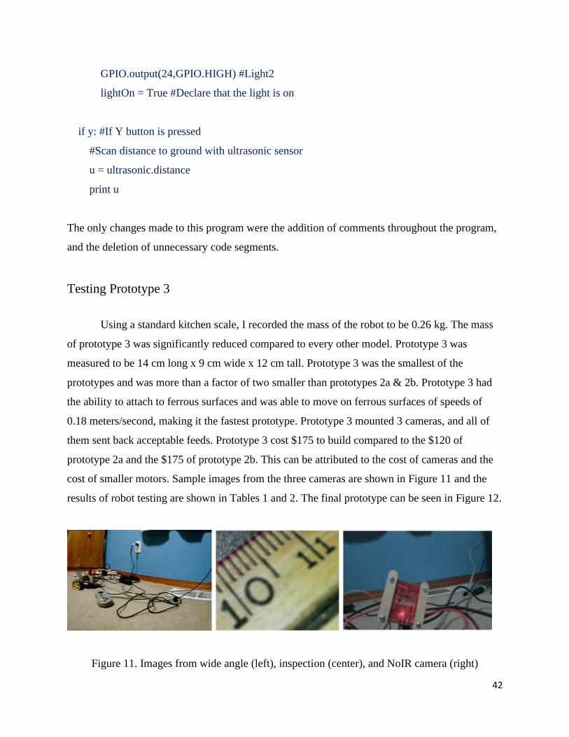
cost of smaller motors. Sample images from the three cameras are shown in Figure 11 and the
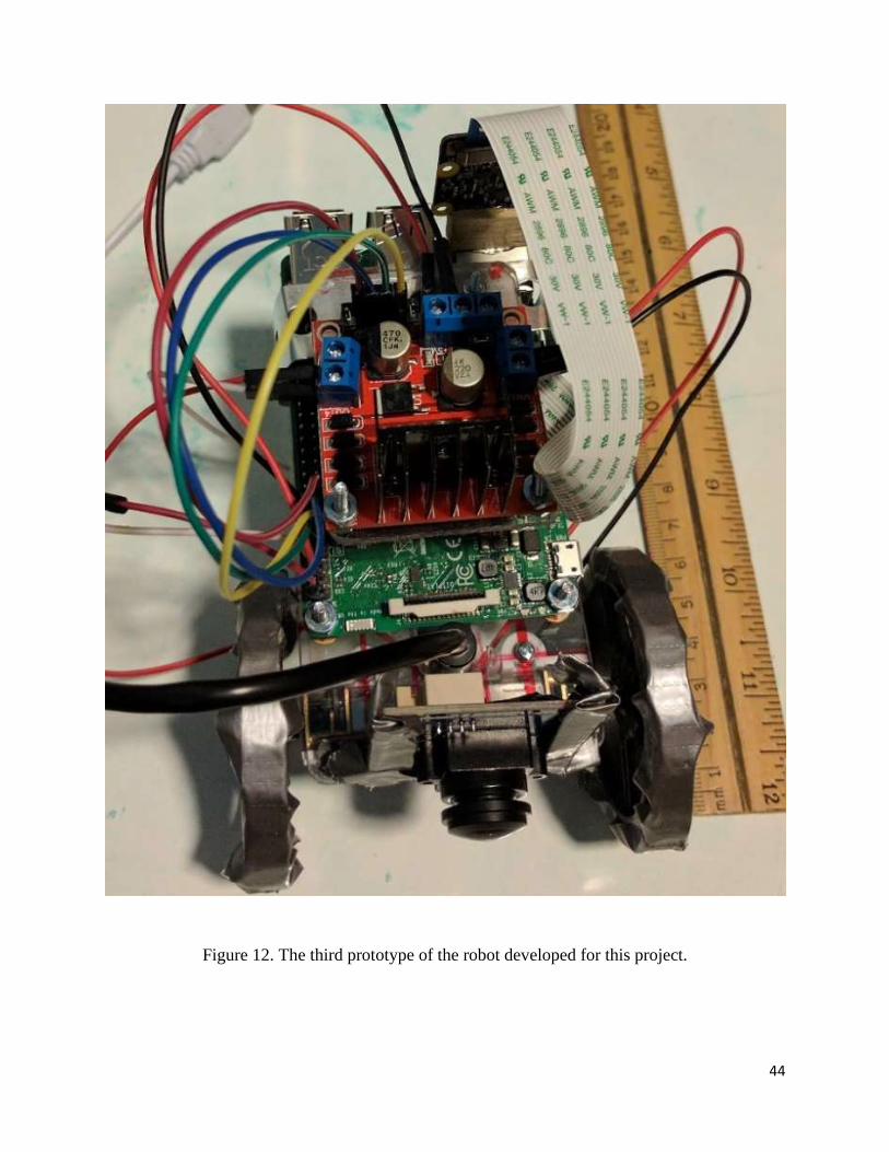
results of robot testing are shown in Tables 1 and 2. The final prototype can be seen in Figure 12.
Figure 11. Images from wide angle (left), inspection (center), and NoIR camera (right)

43
Table 1. Time trials for robot prototype 3 on a vertical wall.
Table 2. Comparison of the performance and features of different prototypes
Prototype 3: Time(s) to travel 1 meter vertically
Climb up Climb down
Trial 1 5.9 2.9
Trial 2 5.3 3.0
Trial 3 5.6 3.1
Trial 4 5.4 3.0
Trial 5 5.5 2.5
Average 5.5 ± 0.2 s 2.9 ± 0.2 s
Speed (m/s) 0.18 0.34
Prototype 1 Prototype 2a Prototype 2b Prototype 3
Mass (kg) 0.92 0.66 0.71 0.26
Size (cm) 27x15x14 15x18x12 15x18x12 14x9x12
Torque (Nm) 4x0.17 2x0.1 2x0.87 2x0.50
Vertical climb up
speed (m/s)
0.0
Did not move
0.0
Did not climb up
0.03 0.18
Cameras 0 1 3 3
Cost* > $400 $120 $170 $175
44
Figure 12. The third prototype of the robot developed for this project.
45
5. Conclusion and Outlook
In this project, I designed, prototyped, developed, programmed and tested several
versions of a small, inexpensive robot for inspection of ferromagnetic structures. I attached an
ultrasonic distance sensor to demonstrate sensor integration. The project resulted in several
innovations including robot design, wheel design and magnet placement, and custom code
created for the robot.
Magnetic inspection robots have high potential for future research and
commercialization. America’s infrastructure continues to age, but there is still no efficient and
cost-effective method of structural inspection. While there are a few prototypes and new robots
out on the market or in testing, there is still no inspection robot that has been widely adopted to
meet the demand. This point is illustrated by the fact that every robot used to inspect damaged
nuclear reactor at Fukushima in Japan has failed as of March 2017. My robot meets this need
and holds considerable potential for deployment in the field.
My robot can be enhanced using several possible modifications, such as the incorporation
of an advanced ultrasonic sensor for thickness measurement, addition of a scraper for collecting
samples from area of interest, modifications (segmented body) to help the robot go over
obstacles or transition between horizontal and vertical surfaces, the use of near-field technology
to enable communication between multiple robots, the use of better wheel covering instead of
duct tape, and improvements to the magnetic wheels. Other areas of improvement include
downsizing the robot further and adopting an even lighter hardware system than the Raspberry
Pi.
The robot designed and built for this project is ready to perform inspections. I only need
to include much longer cables and a tether. The project succeeded in meeting all the design
requirements.

46
6. Bibliography AETOS Air. (n.d.). Retrieved from AETOS: http://www.aetosgroup.com/
Burmeister, A., Pezeshkian, N., Talke, K., Ostovari, S., Everett, H. R., Hart, A., . . . Nguyen, H.
G. (2014). Design of a Multi-Segmented Magnetic Robot for Hull. Naval Engineers
Journal, 45-52.
D51-N52. (n.d.). Retrieved from K&J Magnetics:
http://www.kjmagnetics.com/proddetail.asp?prod=D51-N52&cat=168
Georgiades, C., German, A., Hogue, A., Liu, H., Prahacs, C., Ripsman, A., . . . Milion, E. (2005).
AQUA: an aquatic walking robot. Intelligent Robots and Systems.
Hanlon, M. O. (2014, September 28). XboxController. Retrieved from GitHub:
https://github.com/martinohanlon/XboxController/blob/master/XboxController.py
Tache, F., Fischer, W., Siegwart, R., Moser, R., & Mondada, F. (2007). Compact magnetic
wheeled robot with high mobility for inspecting complex shaped pipe structures.
Intelligent Robots and Systems, 6.
Tang, X., Zhang, D., Li, Z., & Chen, J. (2012). An Omni-directional Wall-climbing Microrobot
with Magnetic Wheels Directly Integrated with Electromagnetic Micromotors.
International Journal of Advanced Robotic Systems, 9.

47
7. Appendix
Appendix I: Xbox Controller Code
#Martin O'Hanlon
#www.stuffaboutcode.com
#A class for reading values from an xbox controller
# uses xboxdrv and pygame
# xboxdrv should already be running
import pygame
from pygame.locals import *
import os, sys
import threading
import time
import RPi.GPIO as GPIO
import picamera
GPIO.setmode(GPIO.BOARD)
GPIO.setup(12,GPIO.OUT) #Left Backward
GPIO.setup(11,GPIO.OUT) #Left Forward
GPIO.setup(13,GPIO.OUT) #Right Forward
GPIO.setup(15,GPIO.OUT) #Right Backward
camera = picamera.PiCamera()
camera.vflip = True
"""
NOTES - pygame events and values
JOYAXISMOTION
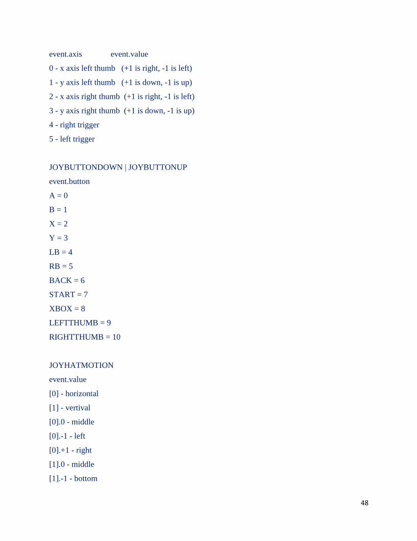
48
event.axis event.value
0 - x axis left thumb (+1 is right, -1 is left)
1 - y axis left thumb (+1 is down, -1 is up)
2 - x axis right thumb (+1 is right, -1 is left)
3 - y axis right thumb (+1 is down, -1 is up)
4 - right trigger
5 - left trigger
JOYBUTTONDOWN | JOYBUTTONUP
event.button
A = 0
B = 1
X = 2
Y = 3
LB = 4
RB = 5
BACK = 6
START = 7
XBOX = 8
LEFTTHUMB = 9
RIGHTTHUMB = 10
JOYHATMOTION
event.value
[0] - horizontal
[1] - vertival
[0].0 - middle
[0].-1 - left
[0].+1 - right
[1].0 - middle
[1].-1 - bottom
49
[1].+1 - top
"""
#Main class for reading the xbox controller values
class XboxController(threading.Thread):
#internal ids for the xbox controls
class XboxControls():
LTHUMBX = 0
LTHUMBY = 1
RTHUMBX = 2
RTHUMBY = 3
RTRIGGER = 4
LTRIGGER = 5
A = 6
B = 7
X = 8
Y = 9
LB = 10
RB = 11
BACK = 12
START = 13
XBOX = 14
LEFTTHUMB = 15
RIGHTTHUMB = 16
DPAD = 17
#pygame axis constants for the analogue controls of the xbox controller
class PyGameAxis():
LTHUMBX = 0
LTHUMBY = 1
50
RTHUMBX = 2
RTHUMBY = 3
RTRIGGER = 4
LTRIGGER = 5
#pygame constants for the buttons of the xbox controller
class PyGameButtons():
A = 0
B = 1
X = 2
Y = 3
LB = 4
RB = 5
BACK = 6
START = 7
XBOX = 8
LEFTTHUMB = 9
RIGHTTHUMB = 10
#map between pygame axis (analogue stick) ids and xbox control ids
AXISCONTROLMAP = {PyGameAxis.LTHUMBX: XboxControls.LTHUMBX,
PyGameAxis.LTHUMBY: XboxControls.LTHUMBY,
PyGameAxis.RTHUMBX: XboxControls.RTHUMBX,
PyGameAxis.RTHUMBY: XboxControls.RTHUMBY}
#map between pygame axis (trigger) ids and xbox control ids
TRIGGERCONTROLMAP = {PyGameAxis.RTRIGGER: XboxControls.RTRIGGER,
PyGameAxis.LTRIGGER: XboxControls.LTRIGGER}
#map between pygame buttons ids and xbox contorl ids
BUTTONCONTROLMAP = {PyGameButtons.A: XboxControls.A,
51
PyGameButtons.B: XboxControls.B,
PyGameButtons.X: XboxControls.X,
PyGameButtons.Y: XboxControls.Y,
PyGameButtons.LB: XboxControls.LB,
PyGameButtons.RB: XboxControls.RB,
PyGameButtons.BACK: XboxControls.BACK,
PyGameButtons.START: XboxControls.START,
PyGameButtons.XBOX: XboxControls.XBOX,
PyGameButtons.LEFTTHUMB: XboxControls.LEFTTHUMB,
PyGameButtons.RIGHTTHUMB: XboxControls.RIGHTTHUMB}
#setup xbox controller class
def __init__(self,
controllerCallBack = None,
joystickNo = 0,
deadzone = 0.1,
scale = 1,
invertYAxis = False):
#setup threading
threading.Thread.__init__(self)
#persist values
self.running = False
self.controllerCallBack = controllerCallBack
self.joystickNo = joystickNo
self.lowerDeadzone = deadzone * -1
self.upperDeadzone = deadzone
self.scale = scale
self.invertYAxis = invertYAxis
self.controlCallbacks = {}
52
#setup controller properties
self.controlValues = {self.XboxControls.LTHUMBX:0,
self.XboxControls.LTHUMBY:0,
self.XboxControls.RTHUMBX:0,
self.XboxControls.RTHUMBY:0,
self.XboxControls.RTRIGGER:0,
self.XboxControls.LTRIGGER:0,
self.XboxControls.A:0,
self.XboxControls.B:0,
self.XboxControls.X:0,
self.XboxControls.Y:0,
self.XboxControls.LB:0,
self.XboxControls.RB:0,
self.XboxControls.BACK:0,
self.XboxControls.START:0,
self.XboxControls.XBOX:0,
self.XboxControls.LEFTTHUMB:0,
self.XboxControls.RIGHTTHUMB:0,
self.XboxControls.DPAD:(0,0)}
#setup pygame
self._setupPygame(joystickNo)
#Create controller properties
@property
def LTHUMBX(self):
return self.controlValues[self.XboxControls.LTHUMBX]
@property
def LTHUMBY(self):
53
return self.controlValues[self.XboxControls.LTHUMBY]
@property
def RTHUMBX(self):
return self.controlValues[self.XboxControls.RTHUMBX]
@property
def RTHUMBY(self):
return self.controlValues[self.XboxControls.RTHUMBY]
@property
def RTRIGGER(self):
return self.controlValues[self.XboxControls.RTRIGGER]
@property
def LTRIGGER(self):
return self.controlValues[self.XboxControls.LTRIGGER]
@property
def A(self):
return self.controlValues[self.XboxControls.A]
@property
def B(self):
return self.controlValues[self.XboxControls.B]
@property
def X(self):
return self.controlValues[self.XboxControls.X]
@property

54
def Y(self):
return self.controlValues[self.XboxControls.Y]
@property
def LB(self):
return self.controlValues[self.XboxControls.LB]
@property
def RB(self):
return self.controlValues[self.XboxControls.RB]
@property
def BACK(self):
return self.controlValues[self.XboxControls.BACK]
@property
def START(self):
return self.controlValues[self.XboxControls.START]
@property
def XBOX(self):
return self.controlValues[self.XboxControls.XBOX]
@property
def LEFTTHUMB(self):
return self.controlValues[self.XboxControls.LEFTTHUMB]
@property
def RIGHTTHUMB(self):
return self.controlValues[self.XboxControls.RIGHTTHUMB]
55
@property
def DPAD(self):
return self.controlValues[self.XboxControls.DPAD]
#setup pygame
def _setupPygame(self, joystickNo):
# set SDL to use the dummy NULL video driver, so it doesn't need a windowing system.
os.environ["SDL_VIDEODRIVER"] = "dummy"
# init pygame
pygame.init()
# create a 1x1 pixel screen, its not used so it doesnt matter
screen = pygame.display.set_mode((1, 1))
# init the joystick control
pygame.joystick.init()
# how many joysticks are there
#print pygame.joystick.get_count()
# get the first joystick
joy = pygame.joystick.Joystick(joystickNo)
# init that joystick
joy.init()
#called by the thread
def run(self):
self._start()
#start the controller
def _start(self):
self.running = True
imgNum = 1

56
isRec = False
recNum = 1
#run until the controller is stopped
while(self.running):
#react to the pygame events that come from the xbox controller
for event in pygame.event.get():
#thumb sticks, trigger buttons
if event.type == JOYAXISMOTION:
#is this axis on our xbox controller
if event.axis in self.AXISCONTROLMAP:
#is this a y axis
yAxis = True if (event.axis == self.PyGameAxis.LTHUMBY or event.axis ==
self.PyGameAxis.RTHUMBY) else False
#update the control value
self.updateControlValue(self.AXISCONTROLMAP[event.axis],
self._sortOutAxisValue(event.value, yAxis))
#is this axis a trigger
if event.axis in self.TRIGGERCONTROLMAP:
#update the control value
self.updateControlValue(self.TRIGGERCONTROLMAP[event.axis],
self._sortOutTriggerValue(event.value))
#d pad
elif event.type == JOYHATMOTION:
#update control value
self.updateControlValue(self.XboxControls.DPAD, event.value)
if event.value == (0,1): #Forward
GPIO.output(11,GPIO.HIGH) #Left Forward
GPIO.output(13,GPIO.HIGH) #Right Forward
57
elif event.value == (0,-1): #Backward
GPIO.output(12,GPIO.HIGH) #Left Backward
GPIO.output(15,GPIO.HIGH) #Right Backward
elif event.value == (1,0): #Right
GPIO.output(11,GPIO.HIGH) #Left Forward
GPIO.output(15,GPIO.HIGH) #Right Backward
elif event.value == (0,1): #Left
GPIO.output(12,GPIO.HIGH) #Left Backward
GPIO.output(13,GPIO.HIGH) #Right Forward
GPIO.output(12,GPIO.LOW)
GPIO.output(11,GPIO.LOW)
GPIO.output(13,GPIO.LOW)
GPIO.output(15,GPIO.LOW)
#button pressed and unpressed
elif event.type == JOYBUTTONUP or event.type == JOYBUTTONDOWN:
#is this button on our xbox controller
if event.button in self.BUTTONCONTROLMAP:
#update control value
self.updateControlValue(self.BUTTONCONTROLMAP[event.button],
self._sortOutButtonValue(event.type))
if event.button == 0 and event.type == 10:
camera.capture('image' + imgNum + '.jpg')
imgNum = imgNum + 1
if event.button == 1 and event.type == 10:
if isRec == False:
camera.start_recording('video' + recNum + '.h264')
isRec = True
else:

58
camera.stop_recording()
isRec = False
if event.button == 1 and event.type == 10:
if isPrev == False:
camera.start_preview()
isPrev == True
else:
camera.stop_preview()
isPrev == False
#stops the controller
def stop(self):
self.running = False
#updates a specific value in the control dictionary
def updateControlValue(self, control, value):
#if the value has changed update it and call the callbacks
if self.controlValues[control] != value:
self.controlValues[control] = value
self.doCallBacks(control, value)
#calls the call backs if necessary
def doCallBacks(self, control, value):
#call the general callback
if self.controllerCallBack != None: self.controllerCallBack(control, value)
#has a specific callback been setup?
if control in self.controlCallbacks:
self.controlCallbacks[control](value)
#used to add a specific callback to a control
59
def setupControlCallback(self, control, callbackFunction):
# add callback to the dictionary
self.controlCallbacks[control] = callbackFunction
#scales the axis values, applies the deadzone
def _sortOutAxisValue(self, value, yAxis = False):
#invert yAxis
if yAxis and self.invertYAxis: value = value * -1
#scale the value
value = value * self.scale
#apply the deadzone
if value < self.upperDeadzone and value > self.lowerDeadzone: value = 0
return value
#turns the trigger value into something sensible and scales it
def _sortOutTriggerValue(self, value):
#trigger goes -1 to 1 (-1 is off, 1 is full on, half is 0) - I want this to be 0 - 1
value = max(0,(value + 1) / 2)
#scale the value
value = value * self.scale
return value
#turns the event type (up/down) into a value
def _sortOutButtonValue(self, eventType):
#if the button is down its 1, if the button is up its 0
value = 1 if eventType == JOYBUTTONDOWN else 0
return value
#tests
if __name__ == '__main__':

60
#generic call back
def controlCallBack(xboxControlId, value):
print "Control Id = {}, Value = {}".format(xboxControlId, value)
#specific callbacks for the left thumb (X & Y)
def leftThumbX(xValue):
print "LX {}".format(xValue)
def leftThumbY(yValue):
print "LY {}".format(yValue)
#setup xbox controller, set out the deadzone and scale, also invert the Y Axis (for some reason
in Pygame negative is up - wierd!
xboxCont = XboxController(controlCallBack, deadzone = 30, scale = 100, invertYAxis =
True)
#setup the left thumb (X & Y) callbacks
xboxCont.setupControlCallback(xboxCont.XboxControls.LTHUMBX, leftThumbX)
xboxCont.setupControlCallback(xboxCont.XboxControls.LTHUMBY, leftThumbY)
try:
#start the controller
xboxCont.start()
print "xbox controller running"
while True:
time.sleep(1)
#Ctrl C
except KeyboardInterrupt:
print "User cancelled"
#error

61
except:
print "Unexpected error:", sys.exc_info()[0]
raise
finally:
#stop the controller
xboxCont.stop()
Appendix II: Motor Test Code
import RPi.GPIO as GPIO
from time import sleep
GPIO.setmode(GPIO.BOARD)
GPIO.setup(12,GPIO.OUT) #Left Backward
GPIO.setup(11,GPIO.OUT) #Left Forward
GPIO.setup(13,GPIO.OUT) #Right Forward
GPIO.setup(15,GPIO.OUT) #Right Backward
GPIO.output(12,GPIO.HIGH)
sleep(2)
GPIO.output(12,GPIO.LOW)
sleep(1)
GPIO.output(11,GPIO.HIGH)
sleep(2)
GPIO.output(11,GPIO.LOW)
sleep(1)
GPIO.output(13,GPIO.HIGH)
62
sleep(2)
GPIO.output(13,GPIO.LOW)
sleep(1)
GPIO.output(15,GPIO.HIGH)
sleep(2)
GPIO.output(15,GPIO.LOW)
sleep(1)
Appendix III: SNES Controller Code
#Developed By Nikhil Devanathan 2017
#Program to control Raspberry Pi robot with wired USB SNES controller
#Uses directional pad (d-pad) for motor movement
#Leaves button and triggers open for mapping
#Imports necessary packages into python
import pygame #Package that is used for game controller mapping
import RPi.GPIO as GPIO #Allows control over binary pins on Pi
from gpiozero import DistanceSensor
#Sets GPIO pins for motor control
GPIO.setmode(GPIO.BCM)
GPIO.setup(18,GPIO.OUT) #Left Backward
GPIO.setup(17,GPIO.OUT) #Left Forward
GPIO.setup(27,GPIO.OUT) #Right Forward
GPIO.setup(22,GPIO.OUT) #Right Backward
GPIO.setup(23,GPIO.OUT) #Light1\
GPIO.setup(24,GPIO.OUT) #Light2/ Work together to power LED lights
63
#Conifgures ultrasonic sensor
ultrasonic = DistanceSensor(echo = 6, trigger = 5, threshold_distance = 0.02)
#Creates variables for controller mapping
global hadEvent
global x
global y
global a
global b
global up
global down
global left
global right
#Assigns Variables for controller mapping
hadEvent = False
x = False
y = False
a = False
b = False
up = False
down = False
left = False
right = False
#Initializing pygame and controller
pygame.init()
pygame.joystick.init()
j = pygame.joystick.Joystick(0)

64
j.init()
#Defining controller event system
def game_controller(events):
#Defining variables for use in controller event system
global hadEvent
global x
global y
global a
global b
global up
global down
global left
global right
#Searches for an event in the system
for event in events:
#If a button is pressed
if event.type == pygame.JOYBUTTONDOWN:
#Set map values
hadEvent = True
x = j.get_button(0)
y = j.get_button(3)
a = j.get_button(1)
b = j.get_button(2)
#If a button is released
elif event.type == pygame.JOYBUTTONUP:
#Set map values
hadEvent = False
x = j.get_button(0)
65
y = j.get_button(3)
a = j.get_button(1)
b = j.get_button(2)
#If there is axial montion on the directional pad
elif event.type == pygame.JOYAXISMOTION:
#Set values for y axis
hadEvent = True
if event.axis == 1:
if event.value <= -1:
up = True
elif event.value >= 1:
down = True
else:
down = False
up = False
#Set values for x axis
elif event.axis == 0:
if event.value <= -1:
left = True
elif event.value >= 1:
right = True
else:
right = False
left = False
lightOn = False #Value to use with b button light control
#Infinite Loop
while True:
66
#Get an event from the event system
game_controller(pygame.event.get())
#Motor controls beased on directional pad values
if up: #Forward
GPIO.output(17,GPIO.HIGH) #Left Forward
GPIO.output(27,GPIO.HIGH) #Right Forward
elif down: #Backward
GPIO.output(18,GPIO.HIGH) #Left Backward
GPIO.output(22,GPIO.HIGH) #Right Backward
elif right: #Right
GPIO.output(17,GPIO.HIGH) #Left Forward
GPIO.output(22,GPIO.HIGH) #Right Backward
elif left: #Left
GPIO.output(18,GPIO.HIGH) #Left Backward
GPIO.output(27,GPIO.HIGH) #Right Forward
else:
GPIO.output(18,GPIO.LOW) #Reset
GPIO.output(17,GPIO.LOW)
GPIO.output(27,GPIO.LOW)
GPIO.output(22,GPIO.LOW)
if a: #If a is pressed, for holding light on
GPIO.output(23,GPIO.HIGH) #Light1
GPIO.output(24,GPIO.HIGH) #Light2
else: #If a is released, for turning light off
GPIO.output(23,GPIO.LOW) #Light1
GPIO.output(24,GPIO.LOW) #Light2
if b: #If b is pressed, for holding solid light
if lightOn: #If the light is on

67
GPIO.output(23,GPIO.LOW) #Light1
GPIO.output(24,GPIO.LOW) #Light2
lightOn = False #Declare that the light is off
else: #If the light is off
GPIO.output(23,GPIO.HIGH) #Light1
GPIO.output(24,GPIO.HIGH) #Light2
lightOn = True #Declare that the light is on
if y: #If Y button is pressed
#Scan distance to ground with ultrasonic sensor
u = ultrasonic.distance
print u