design and development of a delivery system for green
TRANSCRIPT
University of Texas at El PasoDigitalCommons@UTEP
Open Access Theses & Dissertations
2017-01-01
Design And Development Of A Delivery SystemFor Green Ionic Monopropellants And Testing OfA 22n ThrusterJaclyn Mona MejiaUniversity of Texas at El Paso, [email protected]
Follow this and additional works at: https://digitalcommons.utep.edu/open_etdPart of the Aerospace Engineering Commons
This is brought to you for free and open access by DigitalCommons@UTEP. It has been accepted for inclusion in Open Access Theses & Dissertationsby an authorized administrator of DigitalCommons@UTEP. For more information, please contact [email protected].
Recommended CitationMejia, Jaclyn Mona, "Design And Development Of A Delivery System For Green Ionic Monopropellants And Testing Of A 22nThruster" (2017). Open Access Theses & Dissertations. 501.https://digitalcommons.utep.edu/open_etd/501

DESIGN AND DEVELOPMENT OF A DELIVERY SYSTEM FOR GREEN
IONIC MONOPROPELLANTS AND TESTING OF A 22N THRUSTER
JACLYN MONA MEJIA
Master’s Program in Mechanical Engineering
APPROVED:
Ahsan Choudhuri, Ph.D., Chair
Norman Love, Ph.D.
Bill Tseng, Ph.D.
Charles Ambler, Ph.D.
Dean of the Graduate School

Copyright ©
by
Jaclyn Mona Mejia
2017

Dedication
I want to thank my family, friends, and mentors for illuminating the path in higher education.
You give me the strength, motivation, and guidance to persevere in this journey.

DESIGN AND DEVELOPMENT OF A DELIVERY SYSTEM FOR GREEN
IONIC MONOPROPELLANTS AND TESTING OF A 22N THRUSTER
by
JACLYN MONA MEJIA, B.S. Mechanical Engineering
THESIS
Presented to the Faculty of the Graduate School of
The University of Texas at El Paso
in Partial Fulfillment of the
Requirements
for the degree of
MASTER OF SCIENCE
Department of Mechanical Engineering
THE UNIVERSITY OF TEXAS AT EL PASO
Spring 2017

v
Acknowledgements
I thank Dr. Ahsan Choudhuri, chair of the department of Mechanical Engineering, at the
University of Texas at El Paso, and Dr. Norman Love, professor and mentor of my project for the
guidance along my research. You are of vital importance to my education. I also appreciate the
Missile Defense Agency for awarding this project which provided the opportunity to conduct
research and complete my master’s degree based on this work.
vi
Table of Contents Acknowledgements.............................................................................................................................. v
Table of Contents ................................................................................................................................ vi
List of Tables ..................................................................................................................................... vii
List of Figures ...................................................................................................................................viii
List of Illustrations .............................................................................................................................. ix
Chapter1: Introduction ......................................................................................................................... 1
1.1 Project overview ............................................................................................................................ 1
1.2 Project objectives ........................................................................................................................... 1
1.3 Project approach ............................................................................................................................ 1
1.4 Project relevance ............................................................................................................................ 2
Chapter2: Literature Review................................................................................................................ 3
2.1 Monopropellant propulsion ........................................................................................................... 3
2.2 Catalytic decomposition ................................................................................................................ 5
2.3 Ammonium Dinitramide (ADN) ................................................................................................... 8
2.4 ADN based monopropellant (LMP-103S) ..................................................................................... 9
2.5 Hydroxylammonium nitrates (HAN) based monopropellant AFM-315E ................................... 10
Chapter 3: Bunker Delivery System .................................................................................................. 13
3.1 Introduction to chapter ................................................................................................................. 13
3.2 Experimental approach ................................................................................................................ 14
3.3 Experimental test setup ................................................................................................................ 16
3.4 Chapter conclusion ...................................................................................................................... 42
Chapter 4: Gas/Gas - Thruster Test ................................................................................................... 43
4.1 Introduction to chapter ................................................................................................................. 43
4.2 Test bed design and development approach (delivery system) ................................................... 43
4.4 Modular Thruster Parameters ...................................................................................................... 46
4.5 Test matrix development ............................................................................................................. 47
4.6 Testing ......................................................................................................................................... 48
4.7 Results ......................................................................................................................................... 50
4.8 Future Work ................................................................................................................................. 55
Chapter 5: Conclusion ....................................................................................................................... 56
5.1 Summary of work ........................................................................................................................ 56
References.......................................................................................................................................... 57
Vita .................................................................................................................................................... 59

vii
List of Tables
Table 2.1 Comparison of four green propellants……………………………………..........................5
Table 2.2 Comparison of LMP-103S to hydrazine…………………………………………………10
Table 3.1 description of delivery system…………………………………………………………....16
Table 3.2 Operating conditions for the gas delivery system………………………………………..24
Table 3.3 Operating conditions for liquid delivery system…………………………………………33
Table 4.1 Thruster parameters………………………………………………………………………47
Table 4.2 Test matrix calculations for hot fire testing.……………………………………………...47
Table 4.3 Test Matrix……………………………………………………………………………….50
Table 4.4 Test Results………………………………………………………………………………51
viii
List of Figures
Figure 3.1 Two stage Regulator…………………………………………………………………….21
Figure 3.2 Ball Valve……………………………………………………………………………….21
Figure 3.3 Solenoid Valve…………………………………………………………………………..21
Figure 3.4 Rack with gas K bottles…………………………………………………………………22
Figure 3.5 K-Type Thermocouple…………………………………………………………………..22
Figure 3.6 Pressure Relief Valve…………………………………………………………………....22
Figure 3.7 Omega Mass Flow Meter FMA 1700A/1800A Series………………………………….23
Figure 3.8 Swagelok Spring Loaded Check Valve…………………………………………………23
Figure 3.9 MASS Port……………………………………………………………………………....23
Figure 3.10 Pressure Transducer……………………………………………………………………24
Figure 3.11 Two Stage Regulator…………………………………………………………………...29
Figure 3.12 Swagelok Ball Valve…………………………………………………………………...29
Figure 3.13 Solenoid Valve………………………………………………………………………....29
Figure 3.14 K-Type Thermocouple………………………………………………………………....30
Figure 3.15 Pressure Transducer……………………………………………………………………30
Figure 3.16 Swagelok Pressure Relief Valve……………………………………………………….30
Figure 3.17 Swagelok Micro-Particle Filter………………………………………………………...31
Figure 3.18 Turbine Flow Meter……………………………………………………………………31
Figure 3.19 MASS Port……………………………………………………………………………..31
Figure 3.20 Sample Cylinder………………………………………………………………………..32
Figure 3.21 Exhaust duct…………………………………………………………………………....35
Figure 3.22 Exhaust system fan…………………………………………………………………….35
Figure 3.23 Power supply box……………………………………………………………………....37
Figure 3.24 Laser DAQ……………………………………………………………………………..37
Figure 3.25 Relays for solenoid valves……………………………………………………………..38
Figure 3.26 Voltage generator……………………………………………………………………....38
Figure 3.27 Spark plug voltage generator…………………………………………………………..38
Figure 3.28 Pressure transducer amplifier…………………………………………………………..39
Figure 3.29 DAQ flow meters……………………………………………………………………....39
Figure 3.30 DAQ Pressure transducers……………………………………………………………..39
Figure 3.31 DAQ Thermocouple…………………………………………………………………....40
Figure 3.32 Laser…………………………………………………………………………………....40
Figure 3.33 Camera…………………………………………………………………………………40
Figure 3.34 PC & UPS……………………………………………………………………………...41
Figure 3.35 Bunker Patch panel ……………………………………………………………………41
Figure 3.36 Control room patch panel ……………………………………………………………...41
Figure 4.1Thruster…………………………………………………………………………………..48
Figure 4.2 Torsional thrust stand…………………………………………………………………....49
Figure 4.3 Precaution rail…………………………………………………………………………...49
Figure 4.4 Emergency button……………………………………………………………………….49
Figure 4.5 Kevlar wall……………………………………………………………………………....50
ix
List of Illustrations
Illustration 2.1 Monopropellant thruster……………………………………………………………...4
Illustration 2.2 Energy Profile Diagram……………………………………………………………...7
Illustration 2.3 Molecular Collisions…………………………………………………………............8
Illustration 2.4 Thermal decomposition of 40% HAN in a batch reactor…………………………..11
Illustration 2.5 Thermal decomposition of 40% HAN in a batch reactor with a 10% Platinum
Coated/ Alumina Substrate catalyst added………………………………………………………….12
Illustration 3.1 Delivery system 3D CAD model …………………………………………………..19
Illustration 3.2 Delivery system component schematic …………………………………………….19
Illustration 3.3 LabView front panel for the gas delivery system…………………………………..24
Illustration 3.4 Lab View front panel for the gas delivery system (closer look) ...………………....25
Illustration 3.5 Lab View front panel for the gas delivery system (closer look) ...………………....25
Illustration 3.6 Gas delivery system ………………………………………………………………..26
Illustration 3.7 Liquid propellant delivery system.…………………………………………………27
Illustration 3.8 LabView Front panel for the liquid delivery system……………………………….32
Illustration 3.9 Inert gas feed system………………………………………………………………..33
Illustration 3.10 liquid propellant delivery system………………………………………………….34
Illustration 3.11 Exhaust fan setup with mass……………………………………………………....35
Illustration 4.1 Component schematic - leak check & pressure drop measurement………………..44
Illustration 4.2 Delivery System Components Outside of the MASS………………………………45
Illustration 4.3 Components inside MASS………………………………………………………….45
Illustration 4.4 Test Matrix in a graph showing how CO2 increases ………………………………51
Illustration 4.5 35% CO2 Fire………………………………………………………………………52
Illustration 4.6 35% CO2 Fire extinguishing.………………………………………………………52
Illustration 4.7 46% CO2 Fire………………………………………………………………………52
Illustration 4.8 46% CO2 Fire extinguishing.………………………………………………………53
Illustration 4.9 49% CO2 Fire…………………..…………………………………………………..53
Illustration 4.10 49% CO2 Fire extinguishing.…………..…………………………………………53
Illustration 4.11 Catalyst failure…...……………..…………………………………………………54
Illustration 4.12 10 pictures 0% CO2 fire……………...…………………………………………...54
1
Chapter1: Introduction
1.1 Project overview
LMP-103S and AFM-315E are emerging propellants that are less toxic to the environment than the
propellants currently being used in spacecraft propulsion. Both propellants are a blend of liquid fuel,
oxidizer and a majority percent of water. The diluted solutions enable the capability to handle and
store the propellants with fewer requirements; for this reason, it decreases the overall cost of the
propellants since it needs less precautions. The Missile Defense Agency (MDA) awarded the
University of Texas at El Paso (UTEP) a contract to further research green propellants and eventually
replace Hydrazide.
1.2 Project objectives
The project has three main objectives; the first objective is to design and develop both a gas and
a liquid delivery system along with a program to control and record data from both feed systems. The
second objective is to leak check both systems and run cold flow tests with nitrogen gas to verify
pressure drop in facility. The third objective is to test a 22-N thruster. All tasks have been completed
at this point.
1.3 Project approach
In order to reach the objectives, the project was divided into sections and each semester tasks
within each section were completed. The project was approached in the following timeline. The first
semester, the team designed both the gas and the liquid feed systems. The team created required
documents, CAD models, hand calculations, computerized models, and literature review for material
compatibility. The second semester, the team procured all components and assembled both delivery
systems. The third semester, the lab view program was created along with all the electrical
2
connections needed to control and record data from all components. A fourth semester was utilized
to finalize the project. The thruster was tested using the new capabilities of the laboratory.
1.4 Project relevance
The bunker in lab E-105 was not equipped to test green propellants. The need for an expansion
was required to bring more green propellant research to the University. Currently, propulsion
systems utilize hydrazine. This propellant has good performance and it meets all MDA requirements.
On the other hand, this propellant is toxic to the environment and it is difficult to handle. The purpose
of investigating new propellants is to reduce the burden on the environment and reduce issues caused
to personnel storing and handling them. There are three green propellants currently being researched
at the university. For this reason, the delivery systems were created. The liquid delivery system has
three independent feed systems, one for each propellant. The gas delivery system has six independent
feed systems to test six different gasses.

3
Chapter2: Literature Review
2.1 Monopropellant propulsion
Monopropellant thrusters create thrust by expelling hot and high-speed gasses from the
chamber and across the nozzle. The gasses are created by a chemical decomposition that happens
when the propellant passes through a catalyst bed. The catalyst bed enables the propellant to have a
faster decomposition reaction rate that drives a faster energy release. The hot gasses generated by the
energy release in the chemical decomposition flow through a converging-diverging nozzle where the
exhaust gas velocity increases throughout the nozzle, resulting in thrust.
Monopropellant propulsion systems have several advantages compare to other propulsion
systems. One of the advantages is the simplicity of the systems. This system does not require
numerous of components. For example, since it is a monopropellant it only requires one tank. This
advantage drives a second advantage which is weight savings. Another advantage is cost. Since the
propulsion system requires a low number of components, the cost decreases. Ignition simplicity is
another advantage of monopropellant systems. Monopropellant thrusters do not require an ignition
source. The energy release is created by the propellant flowing through the catalyst. Lastly, the control
system only requires valves to open and close. Oppose to bipropellants that require more functions in
the propulsion systems.
Monopropellant propulsion systems have several disadvantages compare to other propulsion
systems. The main disadvantage is the low specific impulse this rocket performs. Monopropellants
are unstable in a storage environment. When the propulsion system is designed, it requires a pressure
relief system. Monopropellants degrade with time inside the storage tank. The concentration of the
propellant diminishes along with the performance of the rocket.
Illustration 2.1 shows a general idea of a monopropellant rocket. Monopropellant thrusters are
composed of a tank to store the single propellant, a solenoid valve to drive the flow from the tank to

4
the catalyst bed, through the chamber, throat, and nozzle. Thruster response time is dependent on the
valve control. A thermal standoff is between the valve and the injector plate. The function for this
standoff is to reduce the amount of heat transfer from the heat released in the catalyst. The catalyst
materials depend on the propellant. For example, the material used for hydrogen peroxide catalyst is
Silver. The material used for hydrazine is granular alumina coated with iridium, also known under
the commercial label Aerojet S-405 (previously made by Shell) [10]. These catalysts are efficient
enough to create enough energy release in the rockets. No external energy source is needed to enable
decomposition. There are monopropellants that need heaters to heat up the propellant before entering
the catalyst bed. These propellants require high temperature for decomposition. As the chemical
decomposition begins a mixture of hot and high-speed gasses drive to the chamber and a converging-
diverging nozzle to produce thrust.
Illustration Error! No text of specified style in document.1Monopropellant thruster
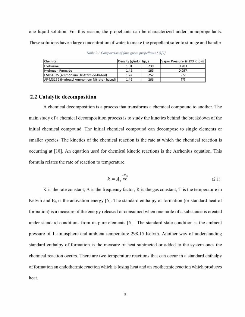
Three monopropellants have been used for flight vehicles: hydrazine, hydrogen peroxide and
propyl nitrate [3]. Hydrogen peroxide degrades 1% of its concentration per year. Propyl nitrate is
shock sensitive [18]. Hydrazine is the best option out of the three, and most monopropellant
propulsion systems use Hydrazine. There are two new bipropellants that behave like a
monopropellant. These two propellants are composed of fuel, oxidizer, stabilizer, and solvent all in
5
one liquid solution. For this reason, the propellants can be characterized under monopropellants.
These solutions have a large concentration of water to make the propellant safer to storage and handle.
Table 2.1 Comparison of four green propellants [3][7]
2.2 Catalytic decomposition
A chemical decomposition is a process that transforms a chemical compound to another. The
main study of a chemical decomposition process is to study the kinetics behind the breakdown of the
initial chemical compound. The initial chemical compound can decompose to single elements or
smaller species. The kinetics of the chemical reaction is the rate at which the chemical reaction is
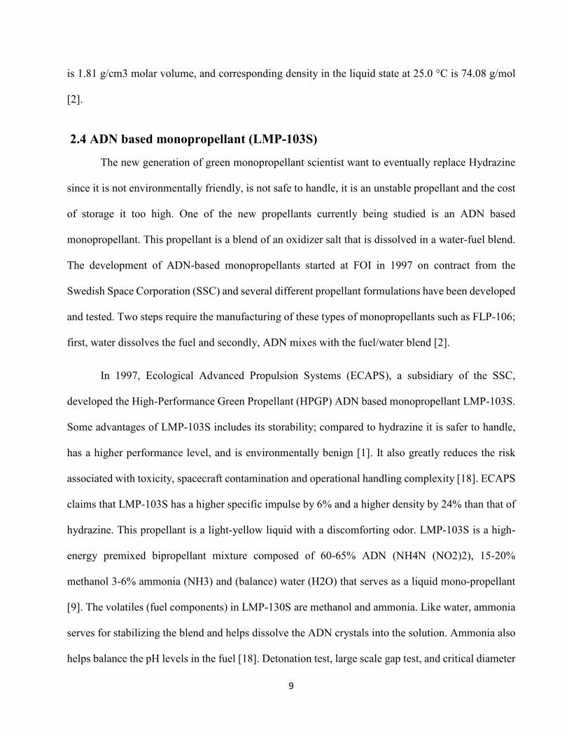
occurring at [18]. An equation used for chemical kinetic reactions is the Arrhenius equation. This
formula relates the rate of reaction to temperature.
� � ��
���
� (2.1)
K is the rate constant; A is the frequency factor; R is the gas constant; T is the temperature in
Kelvin and EA is the activation energy [5]. The standard enthalpy of formation (or standard heat of
formation) is a measure of the energy released or consumed when one mole of a substance is created
under standard conditions from its pure elements [5]. The standard state condition is the ambient
pressure of 1 atmosphere and ambient temperature 298.15 Kelvin. Another way of understanding
standard enthalpy of formation is the measure of heat subtracted or added to the system ones the
chemical reaction occurs. There are two temperature reactions that can occur in a standard enthalpy
of formation an endothermic reaction which is losing heat and an exothermic reaction which produces
heat.

6
Chemical reactions can take different chemical pathways depending on the environment of
the reaction. The rate of a chemical reaction can be increased by the contribution of an additional
substance called a catalyst [4]. Catalysts work by providing an alternative mechanism involving a
different transition state and lower activation energy [18]. It should be known that there are two forms
in which a catalytic reaction can occur; a heterogeneous and homogeneous reaction [8]. The catalyst
typically is in a solid phase and the propellants in a liquid or gas state. In a homogeneous reaction,
the reactants and the catalyst are in the same phase, whether that be a gas or liquid phase [18]. In a
heterogeneous reaction, a phenomenon called adsorption between the reactants and the catalyst
occurs [6]. Adsorption, not to be confused with absorption, allows the molecules from the reactants
to “stick” on the surface of the catalyst. Diverse mechanisms for reactions on surfaces are known,
depending on how the adsorption takes place [6]. The catalysts are reusable since the chemical
decomposition does not change the catalyst composition.
In order for a reaction to occur, the molecules of the reactants must collide with the catalyst
at a minimum energy called the activation energy [5]. This is the amount of energy required for a
reaction to take place. Adsorbed molecules at an active site can then collide with molecules passing
by; these molecular collisions have the energy needed to reach the transition state. For this reason,
catalysts enable reactions that would otherwise be blocked or slowed by a kinetic barrier [6]. The
catalyst increases the reaction rate by allowing the reaction to take place at a lower temperature.
Illustration 2.2 explains the energy profile diagram.

7
Illustration Error! No text of specified style in document.2 Energy Profile Diagram
When a slightly negative atom approaches a double bonded molecule that has a high negative
charge, the atom and the molecule will repulse upon collision [8]. Illustration 2.3 represents the only
collision that leads to a chemical reaction. Therefore, because it is not certain that a reaction will
occur, the chances of reaction may be enhanced through an increase in catalyst concentration [8]. The
surface area of the catalyst is important in the reaction. Increasing the surface of the catalyst will
enable a large amount of positive collisions which increases the chance of a reaction.

8
Illustration 2.3 Molecular Collisions [8]
2.3 Ammonium Dinitramide (ADN)
Ammonia Dinitramide (ADN) was discovered and produced in the Soviet Union during the
1970s and was strictly classified and unknown to the rest of the world until 1988 when SRI in the
USA 8 “reinvented” ADN [5]. It was synthesized and patented in the United States by SRI
International in 1991. It was then later discovered that ADN is highly soluble in polar solvents and
could be used as an oxidizer in liquid propellants [5]. ADN is a high-energy, solid white inorganic
salt of the ammonia cation (NH4)+ and the dinitramide anion (N(NO2)2-. It is hygroscopic and
soluble in water and other polar solvents but not quite as soluble with non-polar solvents [7]. ADN
crystals serve as the oxidizing agent in monopropellants and solid rocket propellants and dissolve in
water which in turn acts as a stabilizer and moderates combustion temperature [18]. ADN has a high
oxygen balance of +25.79 %, melts at 93°C and starts to decompose at approximately 150 °C at a
heating rate of 10 K per minute [7]. Similarly, to ammonium nitrate, the density of ADN at solid state
9
is 1.81 g/cm3 molar volume, and corresponding density in the liquid state at 25.0 °C is 74.08 g/mol
[2].
2.4 ADN based monopropellant (LMP-103S)
The new generation of green monopropellant scientist want to eventually replace Hydrazine
since it is not environmentally friendly, is not safe to handle, it is an unstable propellant and the cost
of storage it too high. One of the new propellants currently being studied is an ADN based
monopropellant. This propellant is a blend of an oxidizer salt that is dissolved in a water-fuel blend.
The development of ADN-based monopropellants started at FOI in 1997 on contract from the
Swedish Space Corporation (SSC) and several different propellant formulations have been developed
and tested. Two steps require the manufacturing of these types of monopropellants such as FLP-106;
first, water dissolves the fuel and secondly, ADN mixes with the fuel/water blend [2].
In 1997, Ecological Advanced Propulsion Systems (ECAPS), a subsidiary of the SSC,
developed the High-Performance Green Propellant (HPGP) ADN based monopropellant LMP-103S.
Some advantages of LMP-103S includes its storability; compared to hydrazine it is safer to handle,
has a higher performance level, and is environmentally benign [1]. It also greatly reduces the risk
associated with toxicity, spacecraft contamination and operational handling complexity [18]. ECAPS
claims that LMP-103S has a higher specific impulse by 6% and a higher density by 24% than that of
hydrazine. This propellant is a light-yellow liquid with a discomforting odor. LMP-103S is a high-
energy premixed bipropellant mixture composed of 60-65% ADN (NH4N (NO2)2), 15-20%
methanol 3-6% ammonia (NH3) and (balance) water (H2O) that serves as a liquid mono-propellant
[9]. The volatiles (fuel components) in LMP-130S are methanol and ammonia. Like water, ammonia
serves for stabilizing the blend and helps dissolve the ADN crystals into the solution. Ammonia also
helps balance the pH levels in the fuel [18]. Detonation test, large scale gap test, and critical diameter
10
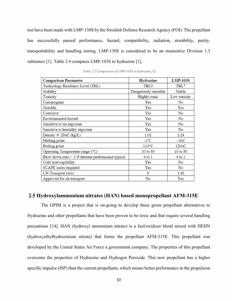
test have been made with LMP-130S by the Swedish Defense Research Agency (FOI). The propellant
has successfully passed performance, hazard, compatibility, radiation, storability, purity,
transportability and handling testing. LMP-130S is considered to be an insensitive Division 1.3
substance [1]. Table 2.4 compares LMP-103S to hydrazine [1].
Table 2.2 Comparison of LMP-103S to hydrazine [1]
2.5 Hydroxylammonium nitrates (HAN) based monopropellant AFM-315E
The GPIM is a project that is on-going to develop these green propellant alternatives to
Hydrazine and other propellants that have been proven to be toxic and that require several handling
precautions [14]. HAN (hydroxyl ammonium nitrate) is a fuel/oxidizer blend mixed with HEHN
(hydroxyethylhydrazinium nitrate) that forms the propellant AFM-315E. This propellant was
developed by the United States Air Force a government company. The properties of this propellant
overcome the properties of Hydrazine and Hydrogen Peroxide. This new propellant has a higher
specific impulse (ISP) than the current propellants, which means better performance in the propulsion
11
system. Also, the density of AFM-315E is higher than Hydrazine and Hydrogen Peroxide enabling
the ability to store more propellant in the same tank volume. Another advantage of this new propellant
is that is safer to handle and stable while in storage.
AF-M315E composition is proprietary and the study of its decomposition it is still not well
understood, but its main component, HAN, has been studied several times [12], [13], [15], [16].
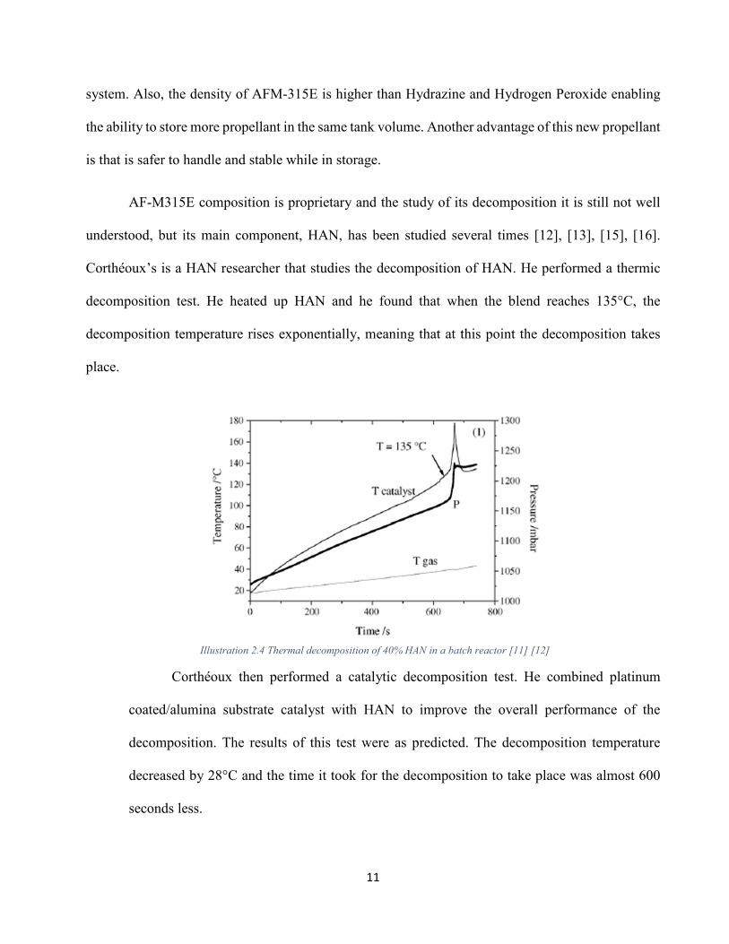
Corthéoux’s is a HAN researcher that studies the decomposition of HAN. He performed a thermic
decomposition test. He heated up HAN and he found that when the blend reaches 135°C, the
decomposition temperature rises exponentially, meaning that at this point the decomposition takes
place.
Illustration 2.4 Thermal decomposition of 40% HAN in a batch reactor [11] [12]
Corthéoux then performed a catalytic decomposition test. He combined platinum
coated/alumina substrate catalyst with HAN to improve the overall performance of the
decomposition. The results of this test were as predicted. The decomposition temperature
decreased by 28°C and the time it took for the decomposition to take place was almost 600
seconds less.

12
Illustration 2.5 Thermal decomposition of 40% HAN in a batch reactor with a 10% Platinum Coated/ Alumina Substrate catalyst
added [11], [12]

13
Chapter 3: Bunker Delivery System
3.1 Introduction to chapter
Chapter 2 established the basic understanding of ADN and HAN including corresponding
decomposition gasses and the ADN-based monopropellant LMP-103S and HAN-based
monopropellant AFM-315E. Based on the information gathered from literature and CEA analysis a
delivery system was expanded to be able to research all gasses and liquid propellants on a bigger
scale. The new delivery system allows evolution and progressive maturity to test green propellants.
Enabling formalization of development and testing strategies for future projects. Multiple
independent thruster testing prevents component/system failure setbacks. Multiple independent
decomposition gas testing prevents component/system failure setbacks. In this Chapter, the design
of the delivery system will be explained in detail.
3.1.1 Introduction
LMP-103S is an Ammonium Dinitramide (ADN) base ionic liquid monopropellant that was
developed by ECAPS, a Swedish Space Corporation (SSC) company. AFM-315E is an (HAN) based
ionic liquid monopropellant that was developed by the air force, a United Stated government
company. The decomposition of these propellants, in theory, will produce an ignitable mixture that
would then combust to produce thrust. The combustion of these species is not fully understood, but
it has been tested previously by studying different flames based on a combination of expected
decomposition gasses.
The development of a delivery system inside the bunker is to be able to test green propellant
capabilities for a range of 5 to 10-pound thrust requirement missions. This chapter will depict the
fundamental capabilities of the delivery system design. The purpose of this project is to design a
universal delivery system in the bunker for different teams to be able to test according to their
14
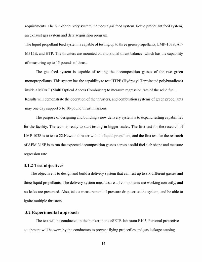
requirements. The bunker delivery system includes a gas feed system, liquid propellant feed system,
an exhaust gas system and data acquisition program.
The liquid propellant feed system is capable of testing up to three green propellants, LMP-103S, AF-
M315E, and HTP. The thrusters are mounted on a torsional thrust balance, which has the capability
of measuring up to 15 pounds of thrust.
The gas feed system is capable of testing the decomposition gasses of the two green
monopropellants. This system has the capability to test HTPB (Hydroxyl-Terminated polybutadiene)
inside a MOAC (Multi Optical Access Combustor) to measure regression rate of the solid fuel.
Results will demonstrate the operation of the thrusters, and combustion systems of green propellants
may one day support 5 to 10-pound thrust missions.
The purpose of designing and building a new delivery system is to expand testing capabilities
for the facility. The team is ready to start testing in bigger scales. The first test for the research of
LMP-103S is to test a 22 Newton thruster with the liquid propellant, and the first test for the research
of AFM-315E is to run the expected decomposition gasses across a solid fuel slab shape and measure
regression rate.
3.1.2 Test objectives
The objective is to design and build a delivery system that can test up to six different gasses and
three liquid propellants. The delivery system must assure all components are working correctly, and
no leaks are presented. Also, take a measurement of pressure drop across the system, and be able to
ignite multiple thrusters.
3.2 Experimental approach
The test will be conducted in the bunker in the cSETR lab room E105. Personal protective
equipment will be worn by the conductors to prevent flying projectiles and gas leakage causing

15
injury in case of a failure. The pressurized system will also be surrounded with Kevlar walls to
prevent any damage to surrounding hardware and instrumentation inside the bunker.
3.2.1 Test 1. Check components are working correctly /System leak test
Turning on lab View and checking the display of each component to match ambient conditions
for the pressure transducers and thermocouples, zero for flow meters, and listening to the solenoid
valves when open, will approve the system components are working correctly.
The test will begin by attaching a ball valve at the end of the components to secure the pressurized
gas. All components will be pressurized to 50 psig using nitrogen gas for the leak check test. The leak
detecting fluid, snoop, will be applied to the perimeter of each fitting. All components will then be
visually inspected to confirm no leaks are present. The components to be leak tested can be seen
below in Illustration 3.2.
3.2.2 Test 2. Measuring pressure drop across the systems
The measurement for pressure drop process will begin by setting the Nitrogen K bottle to
100psi and recording the data from Pc (pressure transducer located at the thruster). This measurement
will allow test conductor to set the K bottles to the right pressure when the hot fire test takes place.
Pressure drop measurement will follow Illustration 3.2
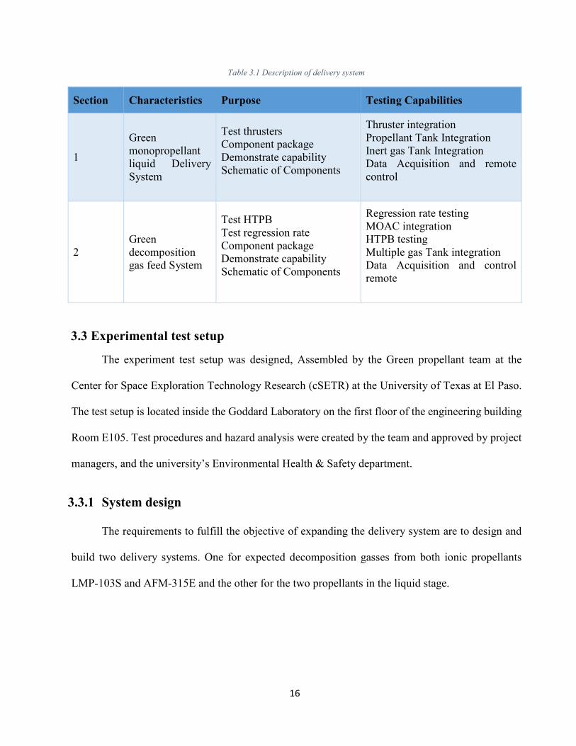
Below is Table 3.1 summarizing the delivery system in two sections the gas and the liquid
delivery systems
16
Table 3.1 Description of delivery system
Section Characteristics Purpose Testing Capabilities
1
Green
monopropellant
liquid Delivery
System
Test thrusters
Component package
Demonstrate capability
Schematic of Components
Thruster integration
Propellant Tank Integration
Inert gas Tank Integration
Data Acquisition and remote
control
2
Green
decomposition
gas feed System
Test HTPB
Test regression rate
Component package
Demonstrate capability
Schematic of Components
Regression rate testing
MOAC integration
HTPB testing
Multiple gas Tank integration
Data Acquisition and control
remote
3.3 Experimental test setup
The experiment test setup was designed, Assembled by the Green propellant team at the
Center for Space Exploration Technology Research (cSETR) at the University of Texas at El Paso.
The test setup is located inside the Goddard Laboratory on the first floor of the engineering building
Room E105. Test procedures and hazard analysis were created by the team and approved by project
managers, and the university’s Environmental Health & Safety department.
3.3.1 System design
The requirements to fulfill the objective of expanding the delivery system are to design and
build two delivery systems. One for expected decomposition gasses from both ionic propellants
LMP-103S and AFM-315E and the other for the two propellants in the liquid stage.
17
3.3.1.1 Liquid propellant delivery system requirements
Design a liquid propellant delivery system for a 5-10-pound thruster, compatible with the green
propellants. In order to test thrust. Along with the design of a remote-control system and data
acquisition from the control room with a lab view program to control devices and record sensor
outputs.
Each propellant requires having identical systems and at the same time individual systems,
meaning each propellant has its own feed system and each system will only be used for the selected
propellant. This is to prevent contamination of components and safety precaution. Propellant
storability is required in a 1 gallon 316 stainless steel sample cylinder. The sample cylinders are
required to have temperature and pressure measurement capability to ensure the propellant is stable.
Both propellants are stable in ambient conditions. The system requires visibility such as a camera
and windows to the system. An exhaust system is required to be able to expel the combustion gasses
when testing due to the hazardous gasses expected. A lab view program is required to control the
flow isolation in the system in case of emergency or part of the test procedure. An inert gas is required
to pressurize the sample cylinder when testing. This gas will control the flow of the propellant. A
pressure relief valve is required for safety precaution in case of the inert gas pressures the propellant
too high during testing. Recording the temperature, pressure, and volume flow rate of the propellant
is required for future calculations and testing precautions. A laser is required when testing a thruster.
It will be the component measuring the force.
3.3.1.2 Decomposition gas delivery system requirements
Design a gas feed system compatible with the decomposition products of green propellants to
perform regression rate analysis and test HTPB inside the MOAC. In addition, develop a remote-
18
control system and data acquisition program from within the control room with a LabVIEW program.
This will allow for valve control and record data from pressure transducers, thermocouples, flow
meters, and camera.
Each gas should have identical systems and at the same time individual systems, meaning
each gas has its own feed system and each system will only be used for the selected gas unless purged
for cleaning. This is to prevent contamination of components and safety precaution. All gas K bottles
are required to be stored in a tank holder with straps for safety precaution. The system requires
visibility such as a camera and windows to the system. An exhaust system is required to be able to
expel the combustion gasses when testing due to the hazardous gasses expected. The premix of the
gasses is required before the ignition component. A lab view program is required to control the flow
isolation in the system in case of emergency or part of the test procedure. A pressure relief valve is
required for safety precaution in case the gas is too high during testing. Recording the temperature,
pressure, and volume flow rate of the gasses is required for future calculations and testing
precautions.
3.3.2 Test setup sub-system development details
The delivery system was designed, and it took several iterations to make sure all requirements
were met. In this section, the different sections of the delivery system will be explained in detail:
Gas Delivery System, Liquid Propellant Delivery System, Exhaust System and Data Acquisition
System. All systems are connected to the MASS (Multiple Altitude Simulator System). Below is a
3D CAD model of the delivery system.
19
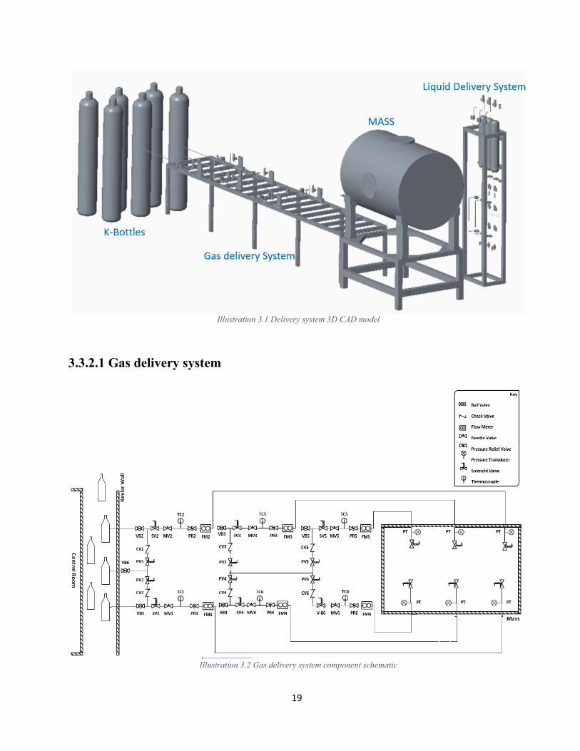
Illustration 3.1 Delivery system 3D CAD model
3.3.2.1 Gas delivery system
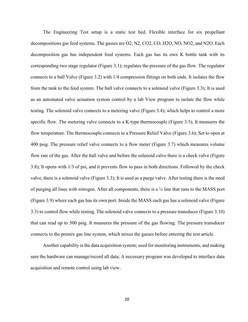
Illustration 3.2 Gas delivery system component schematic
20
The Engineering Test setup is a static test bed. Flexible interface for six propellant
decompositions gas feed systems. The gasses are O2, N2, CO2, CO, H2O, NO, NO2, and N2O. Each
decomposition gas has independent feed systems. Each gas has its own K bottle tank with its
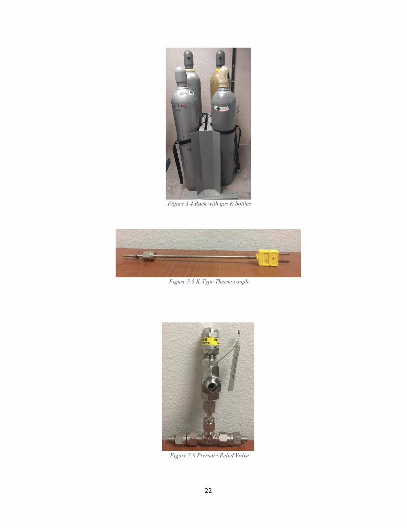
corresponding two stage regulator (Figure 3.1); regulates the pressure of the gas flow. The regulator
connects to a ball Valve (Figure 3.2) with 1/4 compression fittings on both ends. It isolates the flow
from the tank to the feed system. The ball valve connects to a solenoid valve (Figure 3.3); It is used
as an automated valve actuation system control by a lab View program to isolate the flow while
testing. The solenoid valve connects to a metering valve (Figure 3.4); which helps to control a more
specific flow. The metering valve connects to a K-type thermocouple (Figure 3.5); It measures the
flow temperature. The thermocouple connects to a Pressure Relief Valve (Figure 3.6); Set to open at
400 psig. The pressure relief valve connects to a flow meter (Figure 3.7) which measures volume
flow rate of the gas. After the ball valve and before the solenoid valve there is a check valve (Figure
3.8); It opens with 1/3 of psi, and it prevents flow to pass in both directions. Followed by the check
valve, there is a solenoid valve (Figure 3.3); It is used as a purge valve. After testing there is the need
of purging all lines with nitrogen. After all components, there is a ¼ line that runs to the MASS port
(Figure 3.9) where each gas has its own port. Inside the MASS each gas has a solenoid valve (Figure
3.3) to control flow while testing. The solenoid valve connects to a pressure transducer (Figure 3.10)
that can read up to 500 psig. It measures the pressure of the gas flowing. The pressure transducer
connects to the premix gas line system, which mixes the gasses before entering the test article.
Another capability is the data acquisition system; used for monitoring instruments, and making
sure the hardware can manage/record all data; A necessary program was developed to interface data
acquisition and remote control using lab view.

21
Figure 3.1 Two Stage Regulator
Figure 3.2 Ball Valve
Figure 3.3 Solenoid Valve
22
Figure 3.4 Rack with gas K bottles
Figure 3.5 K-Type Thermocouple
Figure 3.6 Pressure Relief Valve

23
Figure 3.7 Omega Mass Flow Meter FMA 1700A/1800A Series
Figure 3.8 Swagelok Spring Loaded Check Valve
Figure 3.9 MASS Port
24
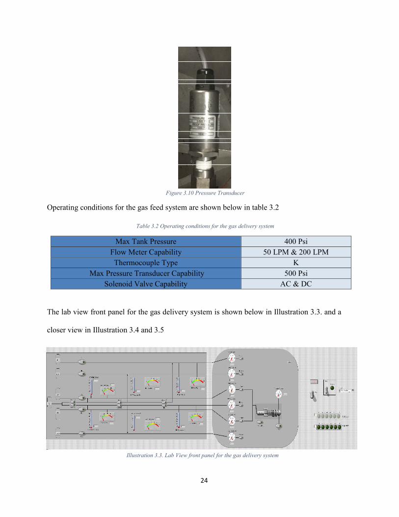
Figure 3.10 Pressure Transducer
Operating conditions for the gas feed system are shown below in table 3.2
Table 3.2 Operating conditions for the gas delivery system
Max Tank Pressure 400 Psi
Flow Meter Capability 50 LPM & 200 LPM
Thermocouple Type K
Max Pressure Transducer Capability 500 Psi
Solenoid Valve Capability AC & DC
The lab view front panel for the gas delivery system is shown below in Illustration 3.3. and a
closer view in Illustration 3.4 and 3.5
Illustration 3.3. Lab View front panel for the gas delivery system

25
Illustration 3.4 Lab View front panel for the gas delivery system (closer look)
Illustration 3.5 Lab View front panel for the gas delivery system (closer look)

26
Below is a picture of the gas delivery system shown in Illustration 3.6
Illustration 3.6. Gas delivery system
.

1
3.3.2.2 Liquid propellant delivery system
Illustration 3.7 Liquid propellant delivery system
The Engineering Test setup is a static test bed. Flexible interface for three liquid propellant
feed systems. Two of the propellants are LMP-13S and AFM-315E. Each liquid propellant has
independent feed systems. Each liquid propellant has its own sample cylinder tank (Figure 3.20)
where the propellant is stored. A K bottle contains the inert gas to pressurize the system. The K
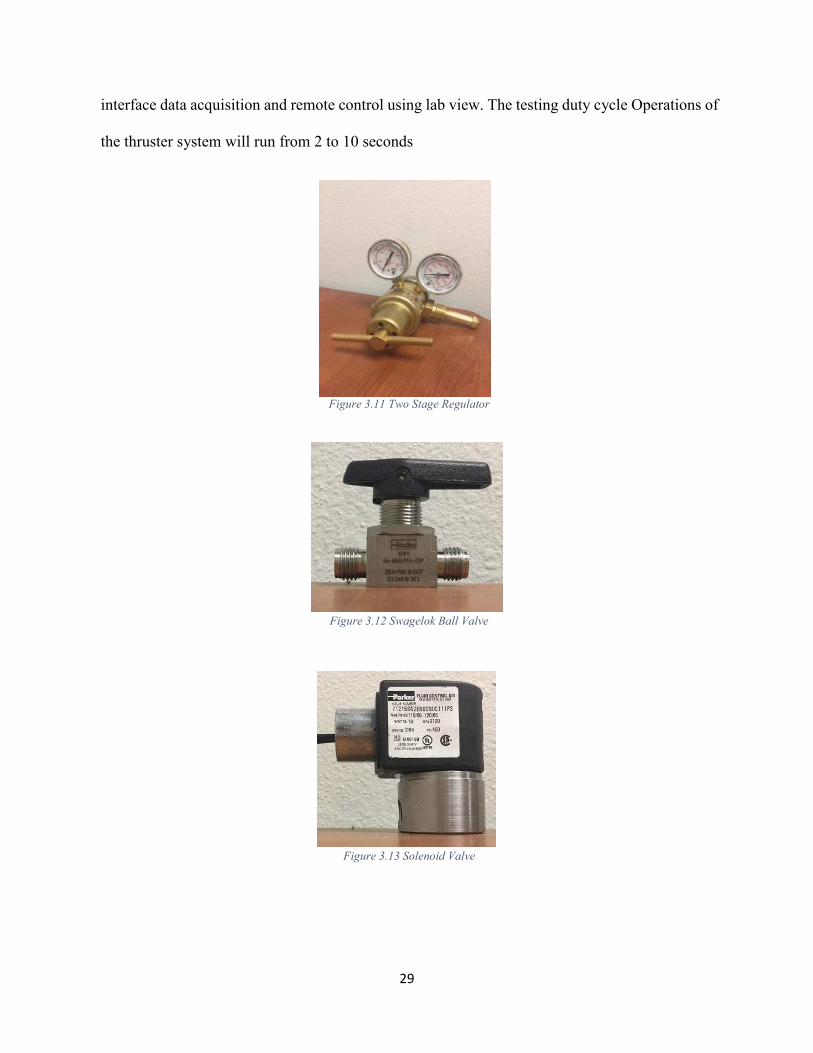
bottle has its corresponding two stage regulator (Figure 3.11). It regulates the pressure of the inert
gas flowing to the sample cylinder to pressurize the propellant when testing. The regulator
connects to a ball Valve (Figure 3.12) with 1/4 compression fittings on both ends. It isolates the
gas flow from the tank to the sample cylinder. The ball valve connects to a solenoid valve (Figure

28
3.13); It is used as an automated valve actuation system control by a lab View program to isolate
the flow while testing. The solenoid valve connects to the sample cylinder where the propellant
is stored. From the sample cylinder, there are three components up steam to have control of the
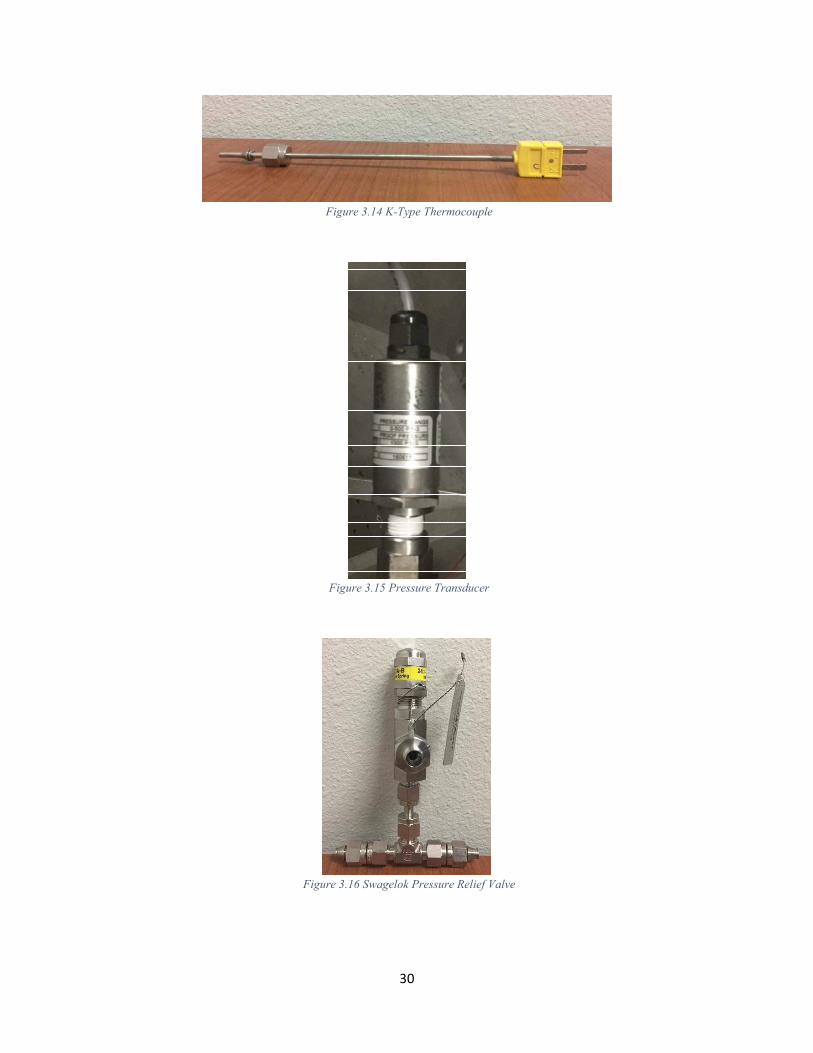
stability of the propellant. First, a K type thermocouple (Figure 3.14); It measures the gas flow
temperature and the temperature of the inner sample cylinder. Second, a pressure transducer
(Figure 3.15) is able to read up to 500 psig; It measures the pressure of the gas flowing and the
pressure inside the sample cylinder. Third, a pressure Relief Valve (Figure 3.16) set to open at
400 psig in case the sample cylinder pressurizes more that needed. Down stream of the propellant
sample cylinder, there is a ball valve (Figure 3.12) to isolate the liquid flow. On the side of that,
there is another ball valve (Figure 3.12) that is used to drain the tank after testing. Connecting the
previous ball valves there is a micro-particle filter (Figure 3.17) to filter any particles collected
from the sample cylinder. The filter connects to two ball valves (Figure 3.12); One the side there
is the bypass which is used when purging to prevent overspin of the flow meter. On the other side,
the ball valve (Figure 3.12) is used to manually open and close the flow path, (to test or to purge).
This ball valve connects to a K-type thermocouple (Figure 3.14); It measures the flow
temperature. The thermocouple connects to a turbine flow meter. (Figure 3.18); which measures
volume flow rate of the liquid. The flow meter connects to 3 ball valves (figure 3.12). First is the
end of the bypass. Second, the ball valve (Figure 3.12) is used to manually open and close the
flow path, (to test or to purge). The third, is a drain valve for the components after testing. These
three valves run one 1/8 line to the MASS port (Figure 3.19) where each liquid propellant has its
own port.
Another capability is the data acquisition system used for monitoring instruments, making
sure the hardware is able to manage/record all data. A necessary program was developed to
29
interface data acquisition and remote control using lab view. The testing duty cycle Operations of
the thruster system will run from 2 to 10 seconds
Figure 3.11 Two Stage Regulator
Figure 3.12 Swagelok Ball Valve
Figure 3.13 Solenoid Valve
30
Figure 3.14 K-Type Thermocouple
Figure 3.15 Pressure Transducer
Figure 3.16 Swagelok Pressure Relief Valve

31
Figure 3.17 Swagelok Micro-Particle Filter
Figure 3.18 Turbine Flow Meter
Figure 3.19 MASS Port

32
Figure 3.20 Sample Cylinder
The lab view front panel for the liquid propellant delivery system is shown below in
Illustration on 3.8.
Illustration 3.8 LabView Front panel for the liquid delivery system
33
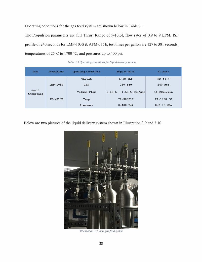
Operating conditions for the gas feed system are shown below in Table 3.3
The Propulsion parameters are full Thrust Range of 5-10lbf, flow rates of 0.9 to 9 LPM, ISP
profile of 240 seconds for LMP-103S & AFM-315E, test times per gallon are 127 to 381 seconds,
temperatures of 25°C to 1700 °C, and pressures up to 400 psi.
Table 3.3 Operating conditions for liquid delivery system
Below are two pictures of the liquid delivery system shown in Illustration 3.9 and 3.10
Illustration 3.9 inert gas feed system

34
Illustration 3.10 liquid propellant delivery system
3.3.2.3 Exhaust system
The exhaust system is used to expel the combustion decomposition gasses out of the MASS
and out of the bunker. An exhaust duck is placed on the end port of the MASS shown in Figure
3.21 the duct connects to the exhaust system fan (Figure 3.22). The fan has an on and off switch.
The fan expels the gasses to the outside environment as shown in Illustration 3.11.
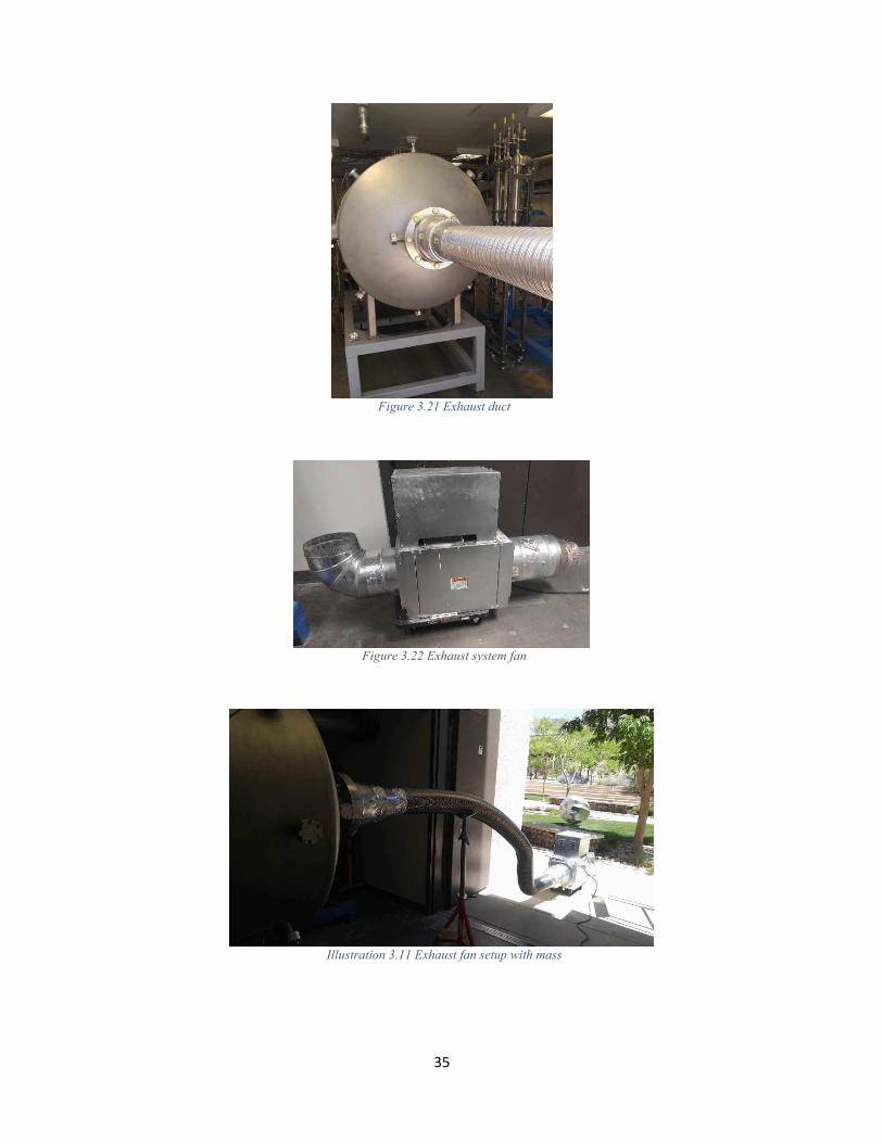
35
Figure 3.21 Exhaust duct
Figure 3.22 Exhaust system fan
Illustration 3.11 Exhaust fan setup with mass
36
3.3.2.4 Data acquisition
The data acquisition program was created to monitor, control and record data such as mass
flow, temperature, and pressure of the delivery system. The mass flow rate is measured with the
flow meters which have an input signal to record the data. The temperature is measured with
thermocouples which have an input signal to record the data. The pressure is measured with the
pressure transducers which have an input signal to record the data. A second capability of the
system is to control the opening and closing of the valves and generate a voltage for the spark
plug; these are controlled by an output signal from the program. The third capability of the system
is to take measurements with a laser. The laser has a separate program ILD1402 Tool V2.03 where
the data is recorded. A camera will record the test inside the MASS using an app on the mobile
phone (play memory).
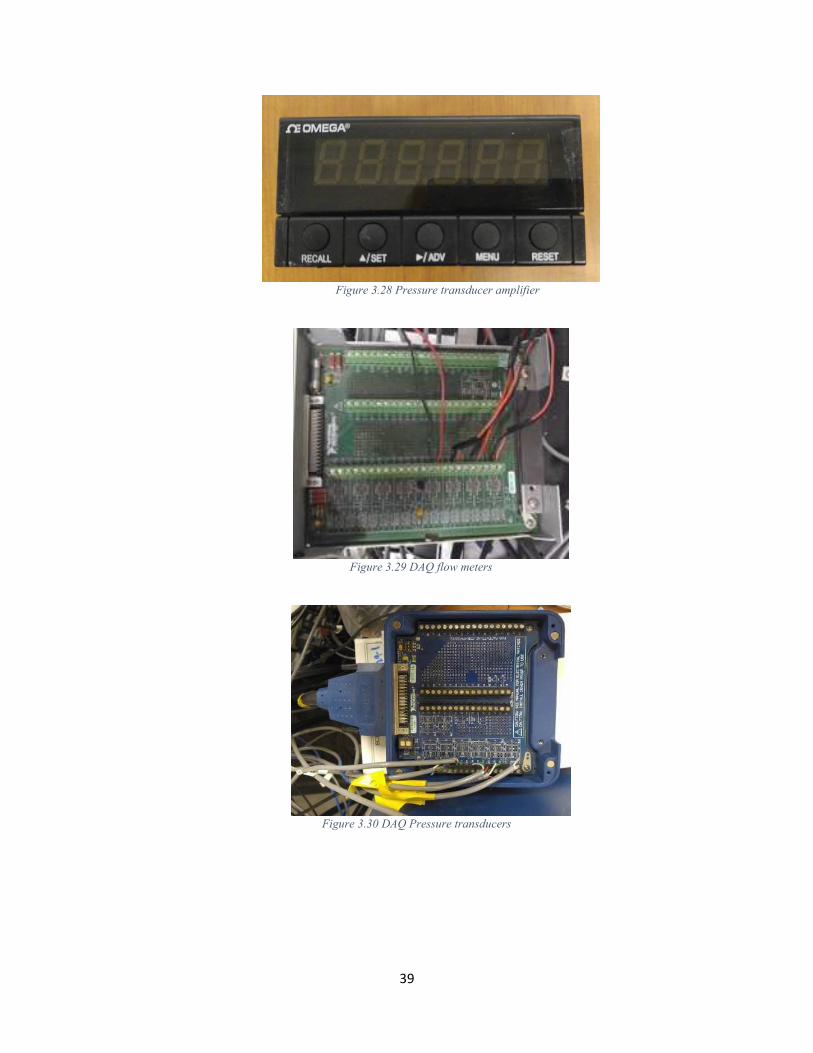
The signal data from the flow meters, static pressure transducers, and thermocouples (K
type) will be acquired through a DAQ (NI SCB – 68A (4.29), NISCB -68A (4.30), and NI SCXI-
1000 (4.31), respectively, and NI LabVIEW program. A program was developed to obtained signal
data for all the measuring devices. Signal conditioners (Figure 3.28) shall amplify pressure
transducers outputs. A connector block (model NI-SCB68) with 12 analog channels will transfer
incoming signals to the program. Flow temperature and pressure data will be recorded and logged
in an LVM file. The actions of opening and closing the gas valves will be done remotely, as
designed for hot firing tests. Relays (Figure 3.25) will be used to send the signal to the valves. The
spark plug utilizes a voltage generator (Figure 3.26) and a spark initiator (Figure 3.27). The laser
(Figure 3.32) utilizes a DAQ (Figure 3.24) with high-speed USB carrier. Laser data will be
recorded and logged in an excel file for data processing. The camera (Figure 3.33) will generate a

37
view for future reference of test and data processing. The power for the data acquisition system
will be supplied by four power supply boxes (Figure 3.23).
For the data analysis, MS excel will be used to analyze the measurements data obtained
from the tests. The LVM file will output to an XML file or text file for the static pressure,
temperature, volumetric flow rates, and laser reading in the gaseous and liquid delivery system.
Figure 3.23 Power supply box
Figure 3.24 Laser DAQ

38
Figure 3.25 Relays for solenoid valves
Figure 3.26 Voltage generator
Figure 3.27 Spark plug voltage generator
39
Figure 3.28 Pressure transducer amplifier
Figure 3.29 DAQ flow meters
Figure 3.30 DAQ Pressure transducers
40
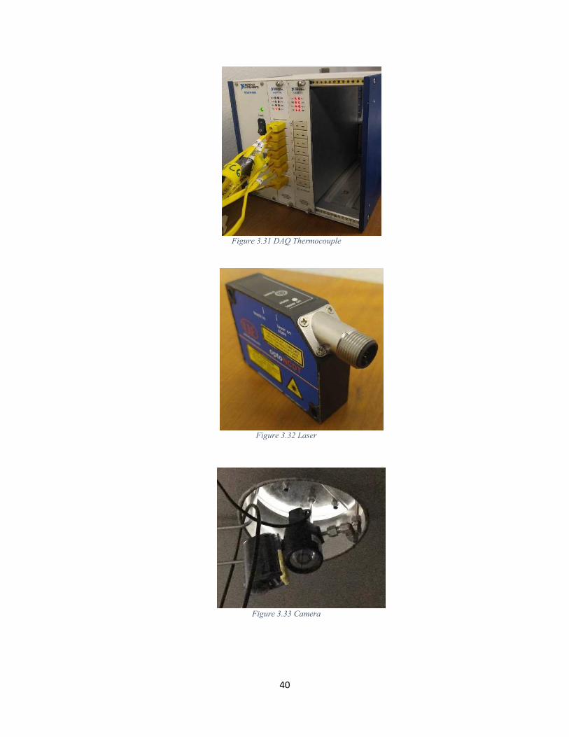
Figure 3.31 DAQ Thermocouple
Figure 3.32 Laser
Figure 3.33 Camera
41
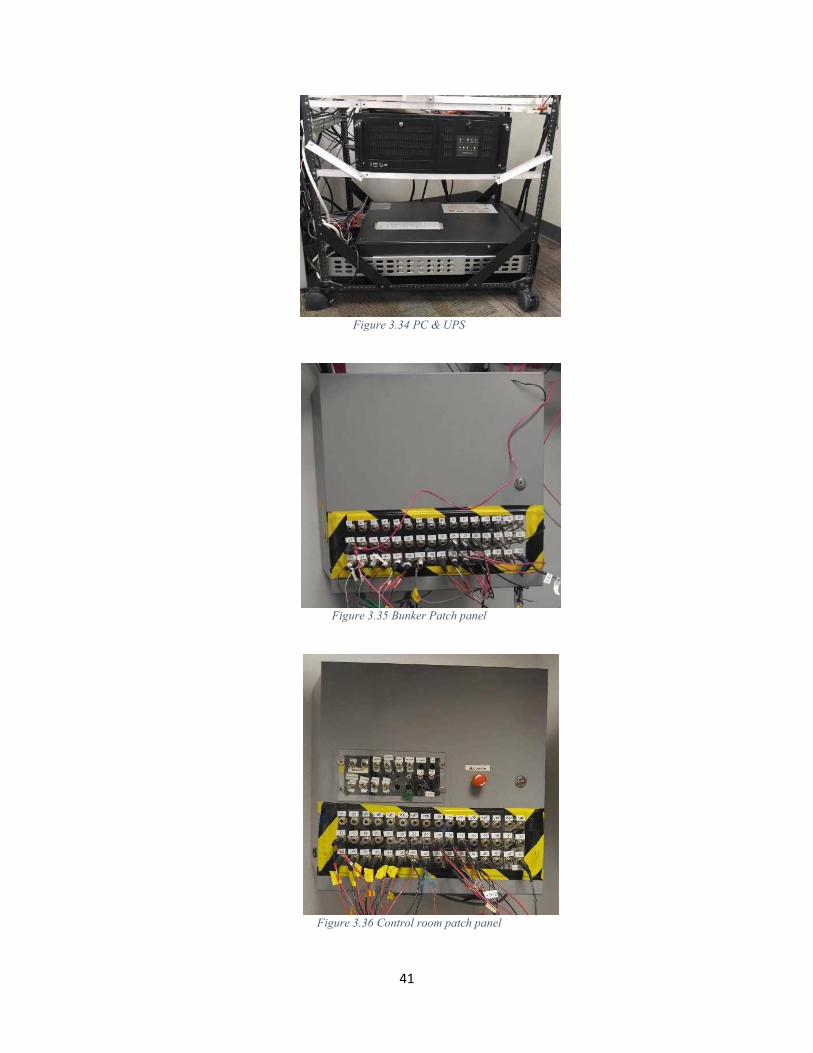
Figure 3.34 PC & UPS
Figure 3.35 Bunker Patch panel
Figure 3.36 Control room patch panel
42
3.4 Chapter conclusion
3.4.1 Leak test:
The setup was pressurized to 50 psig with Nitrogen to check for leaks. The test matrix was
based on previous leak check procedures. The test consists of closing the system and pressurizing
it to 50 psig. Apply the snoop and visually look for any leaks. One of the requirements is to leak
prove the system and the team met the requirement concluding that the delivery system is leak
tested. Prior to a test, it is preferable the system is leak tested as part of the safety precautions.
The step by step procedure is in Appendix A.
3.4.2 Pressure drop measurement
Nitrogen K bottle was set to 100 psig. and the nitrogen flow for 10sec. The test matrix was
based on previous cold flow procedures. The test consists of setting the nitrogen tank regulator to
100 psig and reading the pressure on the pressure transducer (pressure chamber) installed on the
thruster. One of the requirements is to measure the pressure drop across the system, and the team
met the requirement. The step by step procedure for a measurement across the system is found in
Appendix A.

43
Chapter 4: Gas/Gas - Thruster Test
4.1 Introduction to chapter
A 22-N class thruster was designed and developed to test the ADN based monopropellant
LMP-103S. The thruster consists of 5 modules which include a solenoid valve, a thermal isolation
standoff, an injector (distribution plate), propellant feed line, and finally the nozzle/combustion
chamber which also houses the catalyst bed. By injecting the expected decomposition gasses into
the thruster, the combustion of these gasses, in theory, will drive the exhaust gasses through the
nozzle and produce thrust.
The previous chapter explained how the delivery system was designed and built to deliver
the required decomposition gasses to the thruster for testing. Before hot fire testing is conducted
with the thruster, a leak check and cold flow test with Nitrogen took place to ensure the system is
fully functional and operational.
The first objective was to test the delivery system to ensure all components are properly
working and assure no leaks in the system. Secondly, the pressure drop was measured across the
system to validate calculations and know the pressure drop across the catalyst bed. In this chapter,
the last objective will be described in detail. The last objective is to ignite the gas mixture with the
ignition source within the thruster and record data with the lab view program during testing.
4.2 Test bed design and development approach (delivery system)
The test takes place inside the bunker in the cSETR E105 lab. Personal protective
equipment is worn by test conductors to prevent injury in the event of an unexpected failure during
testing. The pressurized system is also surrounded by Kevlar walls to prevent any damage to
surrounding hardware and instrumentation inside the bunker.

44
The process starts by turning on the LabVIEW GUI and checking the channel for each
component. The program should display ambient conditions for the pressure transducers and
thermocouples. It should also display zero for flow meters. By clicking each valve and listening to
the solenoid valves when open will prove the system components are working properly.
The process continues by attaching a plate to the heat bed of the thruster (the combustion
chamber/nozzle module will be removed prior) followed by a ball valve and pressure transducer.
This allows for the thruster to become pressurized. All components are now pressurized to 150
psig using nitrogen gas (N2) for the leak check. The leak detecting fluid, Snoop, is applied to the
perimeter of each fitting. All components are visually inspected to confirm no leaks are present.
The components to be leak tested can be found in blue below in Illustration 4.1
Illustration 4.1 Component schematic - leak check & pressure drop measurement
45
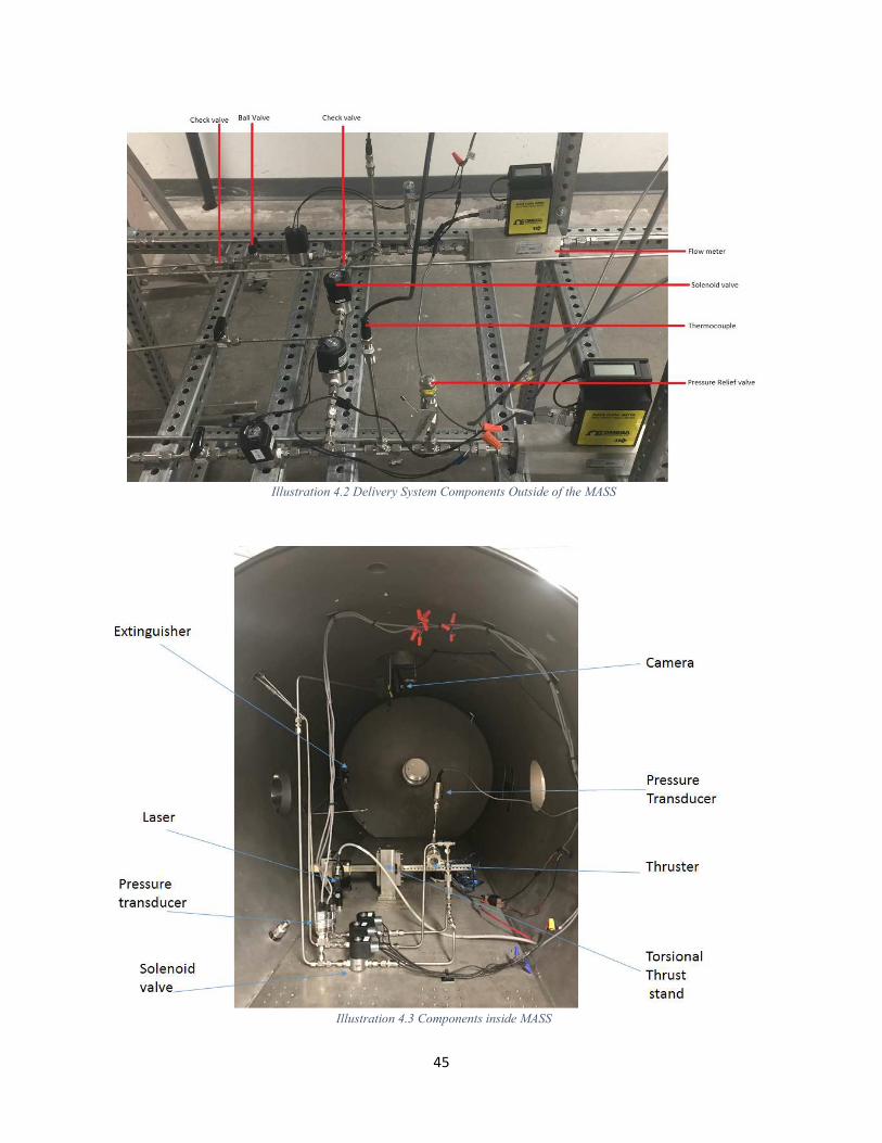
Illustration 4.2 Delivery System Components Outside of the MASS
Illustration 4.3 Components inside MASS
46
The measurement for pressure drop begins by removing the TBV (thruster ball valve) and
replacing it by the chamber nozzle section. A pressure transducer is located right before the thruster
inlet. Another pressure transducer is located at the chamber and it reads chamber pressure. The
Nitrogen K bottle is set to 100 psi. This pressure corresponds to a volumetric flow rate; This flow
rate is shown in the flow meters. The flow rate is larger than what the test requires. The neddle
valves outside the mass will be adjusted until the three flow meters read the correct flow rate
according to the test matrix. The pressure drop across the delivery system and across the thruster
will be recorded by opening the Oxygen purge valve, the Oxygen mass valve and let Nitrogen
flow. The pressure transducer before the thruster will read pressure drop across the delivery
system. The pressure transducer in the chamber will read the pressure drop across the inlet and
catalyst of the thruster.
Performing this procedure allows test conductors to set the K bottles to corresponding
pressures when hot fire testing takes place. The chamber pressure will be added to each tank after
the cold flow with nitrogen.
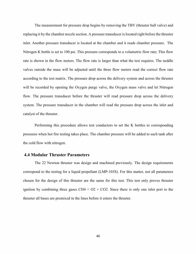
4.4 Modular Thruster Parameters
The 22 Newton thruster was design and machined previously. The design requirements
correspond to the testing for a liquid propellant (LMP-103S). For this matter, not all parameters
chosen for the design of this thruster are the same for this test. This test only proves thruster
ignition by combining three gases CH4 + O2 + CO2. Since there is only one inlet port to the
thruster all bases are premixed in the lines before it enters the thruster.
47
Table 4.1 Thruster Parameters
Thruster Parameters
Throat Cross-Sectional Area (in2) 0.0253
Exit Nozzle Cross-Sectional Area (in2) 0.053
Expansion Ratio (in2) 2.075
L* Characteristic Chamber Length 30
Thruster Material Inconel 625
Wall thickness (in) 0.055
Pressure Transducer port (in) 1/8
Pressure Transducer inside port (in) 0.03
Catalyst Diameter (in) 1
Catalyst Material Silicon Carbide foam
Injector inlet diameter (in) 0.065
Injector expansion cavity (in) 0.9
Feed line (in) 1/8
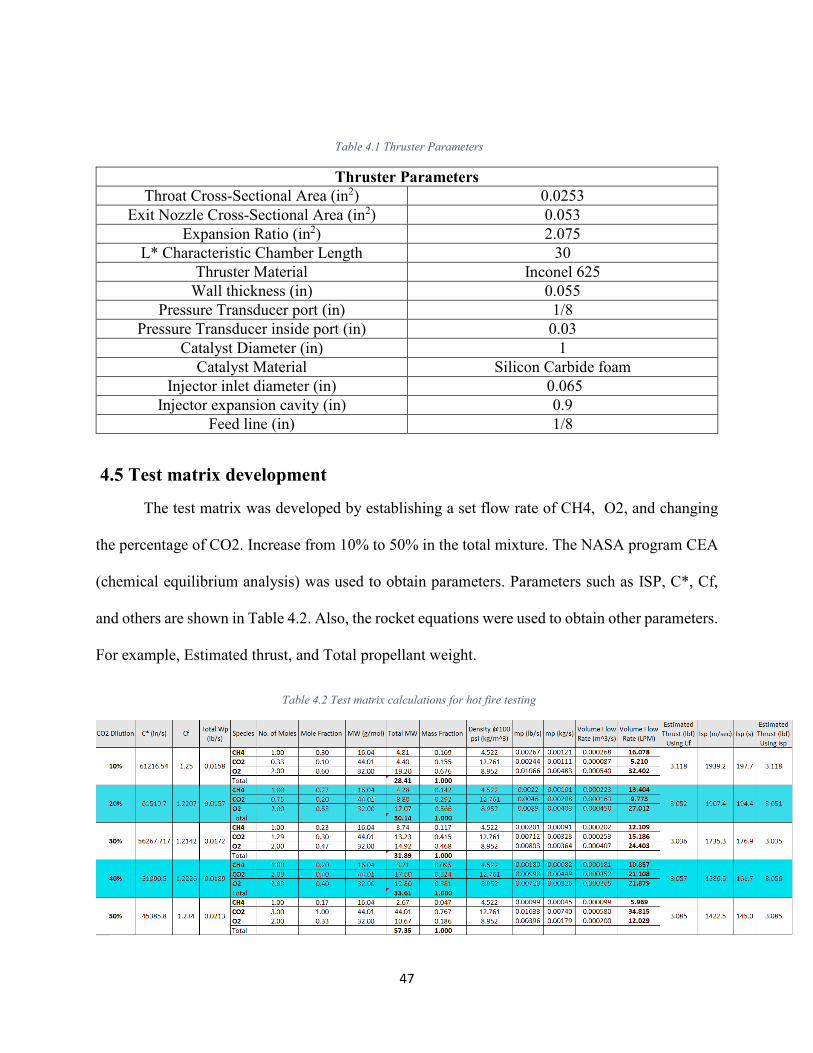
4.5 Test matrix development
The test matrix was developed by establishing a set flow rate of CH4, O2, and changing
the percentage of CO2. Increase from 10% to 50% in the total mixture. The NASA program CEA
(chemical equilibrium analysis) was used to obtain parameters. Parameters such as ISP, C*, Cf,
and others are shown in Table 4.2. Also, the rocket equations were used to obtain other parameters.
For example, Estimated thrust, and Total propellant weight.
Table 4.2 Test matrix calculations for hot fire testing

48
4.6 Testing
The test begins by setting the K bottles to 220 psi. Next, cold flow each line with nitrogen.
This process is described step by step in the test procedure in a different document. Basically, it is
finding the corresponding flow rate in each line by manually adjusting the ball valves outside the
mass. The test runs for ten seconds (automatically). With the camera located inside the MASS, the
test conductors can see the flame and record live footage.
The data was used to check the performance of the system (pressure readings in the thruster
along with expected flow rate readings in the flow meters). The schematic in Illustration 4.1 was
utilized for hot fire testing. Other components are shown below were also used during testing.
Figure 4.1 Thruster (Vertical fittings are the two pressure ports)

49
Figure 4.2 Torsional thrust stand
Figure 4.3 Precaution rail
Figure 4.4 Emergency button

50
Figure 4.5 Kevlar wall
4.7 Results
The testing lasted 4 full days. The objective of the test was to test different percentages of
CO2 in the total volume flow rate of the mixture. Table 4.3 summarizes the tests matrix having 8
different tests.
Table 4.3 Test Matrix
CO2 V flow rate O2 V flow rate CH4 V flow rate CO2
% LPM LPM LPM
0% 12.48 9.56 0.00
4% 10.88 6.50 0.77
8% 10.86 6.94 1.59
9% 10.93 7.29 1.85
16% 12.18 9.56 4.15
35% 10.47 7.29 9.59
43% 10.44 6.87 12.93
49% 10.10 6.64 15.91
51
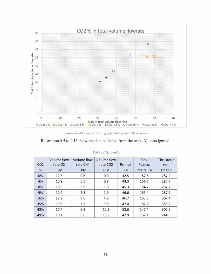
Illustration 4.4 Test matrix in a graph showing how CO2 increases
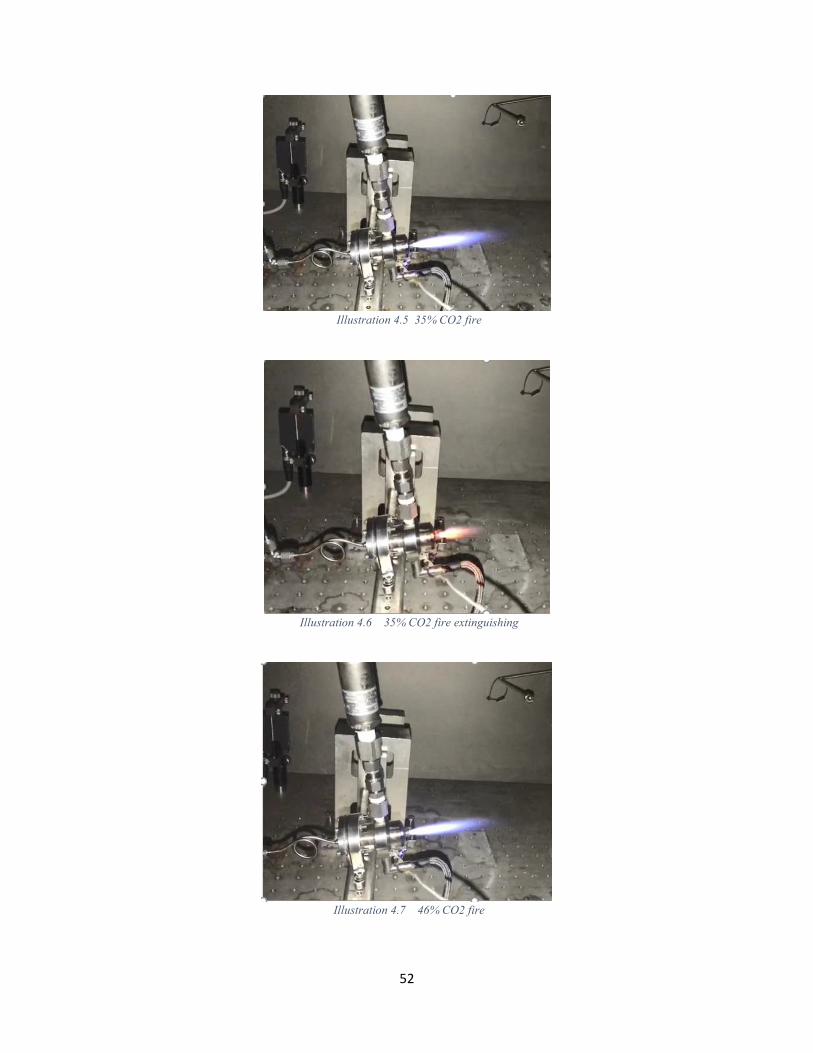
Illustration 4.5 to 4.13 show the data collected from the tests. All tests ignited.
Table 4.4 Test results
0
5
10
15
20
25
30
35
40
45
50
0 10 20 30 40 50 60 70
CH
4
% i
n t
ota
l v
olu
me
flo
wra
te
O2% in total volume flow rate
CO2 % in total volume flowrateCO2 % in total volume flowrateCO2 % in total volume flowrateCO2 % in total volume flowrate
CO2: 0 % CO2: 4 % CO2: 8 % CO2: 9 % CO2: 16 % CO2: 35 % CO2: 43 % CO2: 49 %
CO2
Volume flow
rate O2
Volume flow
rate CH4
Volume flow
rate CO2 Pc max
Tank-
Pc,max
Thruster,c
wall
% LPM LPM LPM Psi Pdelta Psi Tmax C
0% 12.5 9.6 0.0 42.5 157.5 287.0
4% 10.9 6.5 0.8 43.3 156.7 287.7
8% 10.9 6.9 1.6 45.3 154.7 287.7
9% 10.9 7.3 1.9 46.6 153.4 287.7
16% 12.2 9.6 4.2 46.7 153.3 307.4
35% 10.5 7.3 9.6 47.4 152.6 355.2
43% 10.4 6.9 12.9 52.6 147.4 305.6
49% 10.1 6.6 15.9 47.9 152.1 244.5
52
Illustration 4.5 35% CO2 fire
Illustration 4.6 35% CO2 fire extinguishing
Illustration 4.7 46% CO2 fire

53
Illustration 4.8 46% CO2 fire extinguishing
Illustration 4.9 49% CO2 fire
Illustration 4.10 49% CO2 fire extinguishing
54
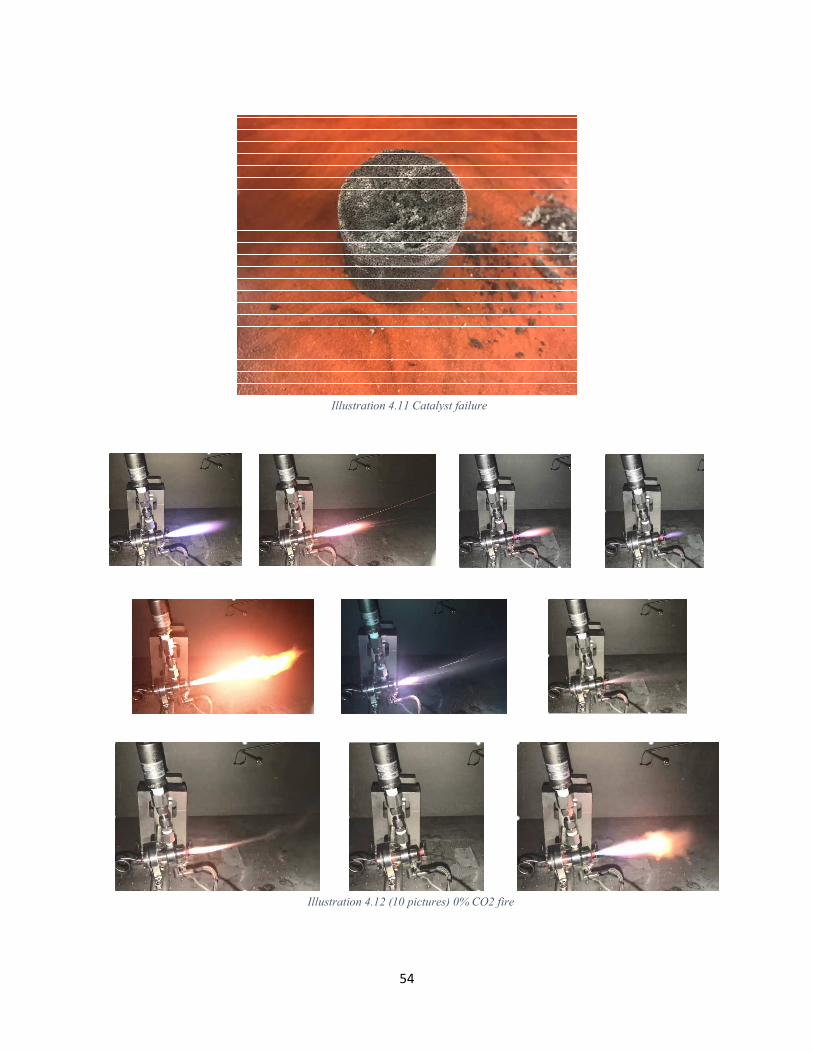
Illustration 4.11 Catalyst failure
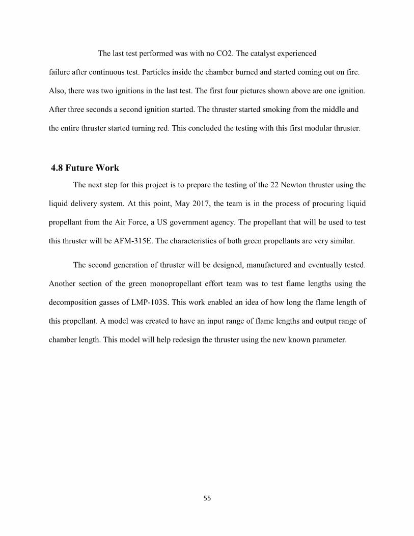
Illustration 4.12 (10 pictures) 0% CO2 fire
55
The last test performed was with no CO2. The catalyst experienced
failure after continuous test. Particles inside the chamber burned and started coming out on fire.
Also, there was two ignitions in the last test. The first four pictures shown above are one ignition.
After three seconds a second ignition started. The thruster started smoking from the middle and
the entire thruster started turning red. This concluded the testing with this first modular thruster.
4.8 Future Work
The next step for this project is to prepare the testing of the 22 Newton thruster using the
liquid delivery system. At this point, May 2017, the team is in the process of procuring liquid
propellant from the Air Force, a US government agency. The propellant that will be used to test
this thruster will be AFM-315E. The characteristics of both green propellants are very similar.
The second generation of thruster will be designed, manufactured and eventually tested.
Another section of the green monopropellant effort team was to test flame lengths using the
decomposition gasses of LMP-103S. This work enabled an idea of how long the flame length of
this propellant. A model was created to have an input range of flame lengths and output range of
chamber length. This model will help redesign the thruster using the new known parameter.

56
Chapter 5: Conclusion
5.1 Summary of work
The green team’s main task was to develop a delivery system to further investigate new
propellants. These ionic monopropellants LMP-103S and AFM-315E are being tested to
understand the compound and create the next generation of the propulsion systems in rockets. The
delivery system was designed and built. The system has a gas fed system and a liquid fed system.
The delivery system was leak tested and a pressure drop measurement was taken. In parallel with
the components, a data acquisition system was created to remote control the system and record
information for data proceeding. The second part of this thesis was to test the 22 Newton thruster
first generation; previously developed by the green propellant team. Based on the results of CEA,
the mixture of Methane, Oxygen, and Carbon dioxide were chosen to test this thruster. Methane,
Oxygen, and Carbon dioxide were delivered to the thruster by the new delivery system and with
the help of the spark plug, the thruster was ignited. Based on this test, the team could assure the
delivery system was working correctly and set requirements for future tests. The thruster provided
useful information such as temperature, and pressure capabilities.

57
References
[1] Neff, K., King, P., Anflo, K. and Möllerberg, R. 2009. “High Performance Green Propellant
for Satellite Applications,” in: Proc. 45th AIAA/ASME/SAE/ASEE Joint Propulsion
Conference & Exhibit AIAA 2009-4878 2 - 5 August 2009, Denver, Colorado
[2] Larson, Anders. Wingborg, N. 2011. “Green Propellants Based on Ammonium Dinitramide
(ADN), Advances in Spacecraft Technologies, Dr. Jason Hal (Ed.), ISBN: 978-953-307-
551-8, InTech, Available from: http://www.intechopen.com/books/
[3] Brown, C. D. 1996. Spacecraft Propulsion. Washington, DC: American Institute of Aeronautics
and Astronautics, Inc.
[4] A. D. McNaught and A. Wilkinson. 1997. IUPAC. Compendium of Chemical Terminology,
2nd ed. (the "Gold Book"). Blackwell Scientific Publications, Oxford. ISBN 0-9678550-
9-8
[5] D. W. Oxtoby, H. P. Gillis, A. Campion. 2012. Principles of Modern Chemistry Seventh
Edition. Belmont, CA: Mary Finch. ISBN-13: 978-0-8400-4931-5
[6] Helmut Knözinger, Karl Kochloefl "Heterogeneous Catalysis and Solid Catalysts" in
Ullmann's Encyclopedia of Industrial Chemistry 2002, Wiley-VCH, Wenham.
doi:10.1002/14356007.a05_313. Article Online Posting Date: January 15, 2003
[7] Nagamachi, M. Y. Oliveira, J. I. S. Kawamoto, A. M. and Dutra, R. d. L. 2009. ‘ADN – The
new oxidizer around the corner for an environmentally friendly smokeless propellant,” in:
Proc. Journal of Aerospace Technology and Management, V. 1, n. 2.
[8] Clark, J. 2002. “Chemguide Physical Chemistry – Kinetic Theory – Chemical Energetics –
Rates of Reaction - Catalysis,”. Retrieved from:
http://www.chemguide.co.uk/physmenu.html#top
[9] Hendrich, C., Gernoth, A., Wingborg, N., Scharlemann, C., Ciezki, H.K. and Schlechtriem, S.
Influence of water content in an ADN based liquid monopropellant on performance
characteristics.
[10] de Nevers, N. (2002). Physical and Chemical Equilibrium for Chemical Engineers. ISBN 978-
0-471-07170-9. 157
[11] Chiaverini, M. 2007. “Review of Solid-Fuel Regression Rate Behavior in Classical and
Nonclasical Hybrid Rocket Motors,” Fundamentals of Hybrid Rocket Combustion and
Propulsion, Progress in Astronautics and Aeronautics, edited by M. Chiavernini and K. K.
Kuo, Vol. 218, AIAA, Reston, VA.
[12] Corthéoux, L., Amariei, D., Rossignol, S., Kappenstein, C. 2006. “Thermal and Catalytic
Decomposition of HNF and HAN liquid ionic as propellants”, Applied Catalysis B:
Environmental. Volume 62. Elsevier.
[13] Corthéoux, L. et al. 2004. “Thermal and Catalytic Decomposition of HNF and HAN-based
propellants”, Proceedings of the 2nd International Conference on Green Propellants for
Space Propulsion, Sardina, Italy.

58
[14] Dunbar, B. 2015. “Green Propellant Infusion Mission (GPIM) Overview”, National
Aeronautics and Space Administration. Edited by Mohon, L. Retrieved from:
http://www.nasa.gov/mission_pages/tdm/green/overview.html
[15] Lee, H., and Litzinger, T. A. 2001. “Thermal Decomposition of HAN-based Liquid
Propellants”, Combustion and Flame, Vol. 127. Elsevier.
[16] Onodaka, S. et. al. 2013. “Ignition Characteristics of HAN Liquid for Gas-Hybrid Rockets”,
49th AIAA/ASME/SAE/ASEE Joint Propulsion Conference. San Jose, CA.
[17] Sutton, G. P., and Biblarz, O. 2001. Rocket Propulsion Elements. 7th ed. John Wiley & Sons:
New York, NY.
[18] Barragan J. M. 2015. Development of an ADN based ionic liquid monopropellant modular
thruster. El Paso TX.
[19] Martinez G. A. 2015. System development for the decomposition of Han-based propellants.
El Paso TX.

59
Vita
Jaclyn Mona was born in El Paso TX on April 12, 1992. Her parents are both UTEP
graduates, Carlos Mario Mejia, BS 1985 and Raquel Mejia, BBA 1985. Both with master degrees.
She was raised as an ex-patriot while her father ran a Multinational Manufacturing company,
Jaclyn was raised with community and family values in Chihuahua City, Chih., Mexico during her
formative years. She attended Colegio Montessori de Chihuahua for her elementary and middle
school education, which focused was on self-motivation, team work and creativity. Then, she
attended Tecnologico de Monterrey, Campus Chihuahua, considered a highly demanding prep-
school, for part of her high school years while actively participating in the soccer team. She
returned home to El Paso, where all her extended family resides and completed high school at
Franklin high school as part of the National Honor society, in June 2010. She selected to continue
her higher education at the University of Texas at El Paso due to its’ excellent engineering program
and vast research opportunities. During her sophomore year, Jaclyn began working for Dr. Ahsan
Choudhuri at the center for Space Exploration Technology Research. She began with cSETR
February 2012 where she worked on several projects under NASA and MDA. In the summer of
2014, Jaclyn had an internship in Houston, NASA’s Johnson Space Center. She obtained her
Bachelors of Science degree in Mechanical Engineering in Spring 2015, also volunteering in
various venues to motivate others to study STEM education. She was accepted into the Master of
Science in Mechanical Engineering program where she graduated in spring 2017. Jaclyn decided
to continue her education and now she is accepted into the Doctoral program in Mechanical
Engineering at UTEP.
Permanent Address: 569 Dorsey Dr.
El Paso, TX. 79912
This thesis was typed by Jaclyn Mona Mejia.