design and develop an apparatus for measurement of
TRANSCRIPT

Journal of Engineering Science and Technology Vol. 15, No. 5 (2020) 2963 - 2985 © School of Engineering, Taylor’s University
2963
DESIGN AND DEVELOP AN APPARATUS FOR MEASUREMENT OF INERTIAL PROPERTIES FOR
A TYPICAL TWO-WHEEL MOTORCYCLE
K. S. TAN1,3,*, S. V. WONG2, 3, M. M. H. MEGAT AHMAD1
1Department of Mechanical Engineering, Faculty of Engineering, National Defence University of Malaysia, 57000 Sungai Besi Camp, Kuala Lumpur, Malaysia
2Department of Mechanical and Manufacturing Engineering, Faculty of Engineering, University Putra Malaysia, 43400 UPM Serdang, Selangor DE, Malaysia
3Road Safety Research Centre, Faculty of Engineering, 43400 UPM Serdang, Selangor DE, Malaysia
*Corresponding Author: [email protected]
Abstract
The inertial properties, both translational and rotational, of an object subjected to motions are crucial information for understanding its dynamics during operation and also design of various practical engineering applications. In the present study, a simple low cost apparatus together with the associated techniques for measuring inertial properties of a motorcycle has been developed. The apparatus was designed to be adapted for a small motorcycle and its variants which typically having an engine capacity of 125±25 cc, a wet mass of about 100±10 kg and a wheelbase of about 1250±50 mm. The apparatus incorporates both the functionalities to determine the CG location, and also the rotational inertia, or the mass moment of inertia (MMI), of motorcycles with respect to the x-, y- and z-axis in orthogonal coordinate system in a few standardized simple steps. The underlying concept of the present designed method are based on a free hanging compound pendulum for locating the CG location of a test object, and based on the theory of periodic oscillation of a pendulum for determining the rotational inertia quantities. The general flow of operation of the measurement was presented, along with the relevant mathematical formulae for calculating the corresponding inertia quantities. Performance of the apparatus was also evaluated and the deviations were found to be within the acceptable range of 2-6%.
Keywords: Centre of gravity, Compound pendulum, Harmonic motion, Mass moment of inertia, Motorcycles, Two-wheelers.
2964 K. S. Tan et al.
Journal of Engineering Science and Technology October 2020, Vol. 15(5)
1. Introduction The translational and rotational inertial properties represent an important feature of a motorcycle since it affects its dynamics and stability during the operation which in turn significantly influence its safety and maneuvering characteristics. The knowledge of the inertial properties is useful not only in the design of motorcycles [1], but also crucial in road crash investigations and reconstructions for predicting the pre- and post-impact motions of a motorcycle [2]. Besides, in the development of computational motorcycle simulation models, on the one hand the inertial information is crucial as a reference data for the fundamental validation of finite element models [3] and on the other hand it serve as input data for multi-body models [4]. Any error in measuring the centre of gravity (CG) and mass moment of inertia (MMI) would affect directly the results of analysis and the validity of the outcomes. Thus a proper tool and method that capable of performing the measurement tasks effectively and efficiently is highly needed. International standards have been established in supporting such efforts, namely ISO 9130 [5] and ISO 9129 [6] for the measurement methods of the CG location and the MMI of motorcycles, respectively. The standards provide the general guidelines and also fundamental principles and concepts for conducting the relevant tests.
The most common practice to measure the CG location of a motorcycle is the static measurement method which based on the conditions of static equilibrium [2]. The method generally measures the individual reactions of the front and rear wheels in a horizontal and also an elevated configuration, and use principles of moments to locate the CG. Compared to that of CG location, measuring the MMI is much more difficult to perform and without a proper tool the process would be tedious and time-consuming. Nieboer et al. [7] dismantled a motorcycle into front wheel, front fork (including handle bar), main frame, rear suspension frame and rear wheel and the MMI was measured by oscillating each of these motorcycle segments around a "knife-edge" (frictionless joint) on a test rig for different segment positions.
Other more popular methods which have been widely used to measure MMI of various solid bodies are bifilar and trifilar pendulums. The test objects ranged from simple components such as mounted and unmounted passenger car and motorcycle tyres [8], rotors [9], engines [10], to a complete vehicle such as passenger cars [11], boats [12], unmanned aerial vehicles (UAVs) [13-15], and aircrafts [16, 17]. The method is based on the fundamental theory of periodic motion of a torsional pendulum, where the test object is set in transverse rotational oscillations that occurs in a horizontal plane about a vertical axis. The rotational inertias are then derived from the clocked average cycle time of the oscillations.
Shakoori et al. [18] investigated three methods, namely compound pendulum, double pendulum and bifilar torsional pendulum, to measure the MMI of a light UAV. It was reported that the bifilar method is much more accurate than the others while the double pendulum suffered from the highest error. Both the bifilar and trifilar methods are found to be susceptible to lateral displacement causing off-centre oscillation which is the major source of error [19, 20].
Though an arrangement with more than three suspension wires, called multifilar is also feasible but it was reported that multifilar pendula suffer from irregular motion as some wires slacken, thereby adversely affecting the results [21, 22]. Thus, the trifilar arrangement is still a more popular choice in the measurement of rotational inertia. However, considering that the methods allowed for only one

Method of Measurement for Inertial Properties of Powered Two-wheelers . . . . 2965
Journal of Engineering Science and Technology October 2020, Vol. 15(5)
oscillation axis, it is indeed not suitable for relatively large and complex-shaped bodies such as vehicles since configuring such test objects at desired orientations is never an easy task. To overcome the disadvantages of the trifilar pendulum method in handling the large test object, a spatial mechanism was proposed to measure MMI of racing motorcycles [23]. The inertia tensor of the rigid body was determined by measuring the frequencies of the small oscillations around the selected axes and then solving a least-squares identification problem. The mechanism involved some forms of instrumentation system for collecting dynamics data from sensors for calculating the MMI.
In the measurement of the inertial properties of a body, information of CG is essential so that the MMI about own CG can also be determined. Thus, streamlining the measurement process for both the quantities in a systematic manner employing only a single tool would help to improve the overall efficiency and effectiveness of a method. Several facilities were developed with such capability, particularly for testing passenger-cars, commercial vehicles and heavy trucks including military vehicles, such as the one presented in US Patent No. 5,177,998 [24] and the Vehicle Inertia Parameter Evaluation Rig II (VIPER II) [25]. The former consists of a test platform having degrees of freedom for performing oscillations in two different perpendicular planes which allowed for configuring of the test vehicle in predetermined orientations. The CG and the pitch and roll inertias are measured by applying stable pendulum concept while the yaw inertia via springs that provide restoring torque. The VIPER II, on the other hand, having multi-piece platform to adapt for vehicles of different size, uses also the similar manner except that the roll inertia was accomplished via unstable pendulum. The CG and MMI were then calculated from the respective mathematical formula of each configuration.
Some advanced automated measurement systems are also available commercially, such as the Vehicle Inertia Measuring Machine (VIMM) developed by the TU Dresden and the CFM Schiller GmbH [26] and the Anthony Best Dynamics’s (ABD) Moment of Inertia Measurement System (MIMS) [27]. Instead of using the gravity or springs to generate oscillations, these facilities use actuators to produce the dynamic motions that generate data required for determining the inertial properties. These facilities usually incorporated with data acquisition and instrumentation system for controlling actuators and collecting data from sensors and therefore are always complicated and costly to be developed. Considering that the aforementioned facilities were designed particularly to support a passenger car and even a truck that weighs typically over metric tonnes, the platform structure is usually relatively heavy especially compared to typical motorcycles. It would be considered as an over design for a motorcycle as a test object having only about 10% of the weight of passenger cars. Consequently, the accuracy and sensitivity of the measurements would be affected and such concern has also been raised in [25] as one of the important design considerations.
An up to date literature review, as presented above, revealed that the development of tools and methods specially designed for systematically determining the CG and MMI of typical motorcycles are very limited. In view of this, the present work was carry out with the object of designing and developing an inertia measurement apparatus (IMA) and the associated measuring techniques capable of measuring both the translational and rotational inertial properties for the motorcycles as the main test object. couple with a method which must be incorporated to maintain the test object stably during the measurement process.

2966 K. S. Tan et al.
Journal of Engineering Science and Technology October 2020, Vol. 15(5)
2. The Underlying Concept of the Current Method The present method is designed based on conditions for equilibrium and periodic motion of a hanging compound pendulum. For a compound pendulum with an arbitrary shape, two different pivot points that significantly separated apart are required for hanging the pendulum freely, one at a time, in order to acquire two intersecting lines that indicate the CG in a plane. In the similar way, the CG can also be located in the third dimension by further hanging the pendulum at the third pivot point in a different plane. In each of the hanging orientations, right after marking the vertical line, the pendulum can just be swung directly to obtain the cycle time for calculating the MMI.
Such concept can be applied in designing a test system consisting of a platform suspended from a pivot point for which a test object is placed on it to form an equivalent compound pendulum, or the suspended platform can be substituted with some suspended fixture for holding a test object. In the simplest form, the design could be a test object directly attached to the pivot point thus itself became the compound platform. However, in practical there is always a need that the predefined axes of a test object to be orientated and aligned to a predefined orthogonal coordinate system. The latter method would have difficulty to meet such requirement. Thus, any design has to take into account the flexibility for orientating the platform or the fixture of the apparatus, or providing customized brackets that would allow for the test object to be configured in the predefined orientations. Then, the CG and so the MMI with reference to the predefined axis of the hanging structure can thus be determined just as in the case of the compound pendulum.
Based on the design concepts set forth, the functional requirements were identified and the associated design criteria were set. The key functions of the IMA are: i) to hold and to support a test object in a stable condition, and ii) to enable a test object to undergo self-oscillations about a predetermined axis for a minimum of 30 cycles by imposing a small initial displacement of about 2°-3°. In accordance to these two functions, the design criteria that were established dictate that the designed platform/fixture i) should have a working space sufficient to cater for a range of sizes of targeted test objects; ii) must be as light as possible for better accuracy and sensitivity but possesses rigidity required to support the test object with minimal undesired vibrations; iii) should have a flexible holding mechanism to adapt to a wide range of designs and sizes, and also to facilitate for configuring a test object in desired orientations; iv) must be as symmetric as possible so that the mathematical manipulations and analytical calculations can be minimized; v) should be supported by measuring techniques with reasonable repeatability; vi) should be easily fabricated and assembled; and viii) can be adapted easily to mechanisms for convenient and safe lifting of a relatively heavy test object such as a motorcycle.
Several design ideas have been explored in accordance to the design criteria set above. One of the ideas was based on the teeter-totter design with the board as a test object supporting platform. Counter-acting moments required for maintaining self-oscillations of the platform would be generated by having mass blocks fastened diametrically to the opposite side of a rotational shaft. Another design idea involved an incorporation of a dual-axis shaft system, comprises of two shafts with their respective longitudinal axes perpendicularly intersect each other and capable of rotating independently of the other. Such design allowed for any structure that

Method of Measurement for Inertial Properties of Powered Two-wheelers . . . . 2967
Journal of Engineering Science and Technology October 2020, Vol. 15(5)
suspended from the shaft to be displaced about the two mutually perpendicular axes simultaneously, or separately oscillates about either axis, by locking one of the shafts while allowing another to rotate.
The role of dual-axis system is twofold. Firstly, by allowing a structure that hung freely to displace in two orthogonal planes simultaneously under its own weight to an equilibrium condition, the CG with reference to both axes can be determined simultaneously in a single step. Secondly, the latter arrangement facilitates the switching of the oscillation axis from one to another without the need to reconfigure the test object orientation. Thus, such design offers an advantage of minimizing the repetitive operations required for reconfiguring the position and orientation of the test object after completing each measurement. An overall effectiveness and efficiency of the test method can thus be improved.
The main challenge indeed lies in the method on how to hold an unstable test object during the operation of the apparatus, especially when it comes to a relatively heavy object such as a motorcycle. Instead of adding various fixture to support the test object from tilting sideways during the test operation, which would complicate the design, a more viable approach would be utilizing the own weight of the test object for balancing purpose. This can be attained via stable pendulum concept, i.e. having the CG of the test object beneath the supporting platform or holding fixture.
Consequently, it follows that the platform is not required, but instead having supporting links pivoted to a rotational structure while a test object is directly attached to and suspended from the other end of the links. To ensure that oscillations occur only about the desired axis of the rotational structure with minimal vibrations, the links should be rigid enough to prevent from bending. For the design of such hanging links, each of them can be constructed from a tube assembly with adjustable length, hung from the dual-axis shaft unit and assembled in a way that the shaft-arm assembly can be configured in symmetric with respect to the transverse vertical planes of the corresponding shaft. Besides to adapt for a varying sizes and shapes of test objects, the flexibility for adjusting the arm length is also essential to facilitate the configuring of the test object in accordance to the predefined axis.
By synthesizing the several design ideas, the initial setup of the designed IMA was thus formed and the design was progressively fine-tuned as it is being fabricated. The final physical setup of the apparatus and the associated measuring techniques will be presented in the following sections.
3. Physical Setup of IMA and Measurement Method The overall assemblage of IMA is presented in Fig. 1. In general, the apparatus constructed of two major structures, namely the main supporting unit and the key dynamic functional unit. The supporting unit consists mainly a pair of upright frames, each formed from assembly of structural steel C-channels. These two frames are separated at a distance but interconnected by an I-beam secured to the top horizontal members of the frames. To provide the required lateral stability, the frame members are also fastened to each other by a pair of cross-linked steel angle bars at the respective lateral sides to the opposing member. The whole assembly is supported on the castor wheels with brakes to facilitate the transfer of the apparatus.

2968 K. S. Tan et al.
Journal of Engineering Science and Technology October 2020, Vol. 15(5)
The key dimensions of the main supporting and dynamic functional unit is presented in Tables 1 and 2, respectively.
Fig. 1. Schematic drawing of the present IMA.
Table 1. Key dimensions of the main supporting unit. Part Dimensions (mm) Materials Top I-beam 155×105×5×7×1910 Mild steel Upright channel member 100×50×10×2300 Mild steel Horizontal channel supporting member 74×40×6×1910 Mild steel Functional unit support channel 74×40×6×1020 Mild steel Lateral support (equal legs angles) 38.1×38.1×3×2050 Mild steel
Table 2. Key dimensions of the dynamic functional unit. Part Dimensions (mm) Materials Main hollow shaft Ø60×3×150 Stainless steel Secondary solid shaft Ø30×900 Stainless steel Bracket housing Ø70×7.5×60 Mild steel Upper arm Ø28.6×1.15×650 Stainless steel Lower arm Ø25.4×1.15×750 Stainless steel
The dynamic functional unit, as the name implies, is the key assembly that allows for the measurement to be carried out, which consists of a number of arms suspended from a dual-axis shaft system. The shaft system, as presented in Fig. 2,

Method of Measurement for Inertial Properties of Powered Two-wheelers . . . . 2969
Journal of Engineering Science and Technology October 2020, Vol. 15(5)
comprises of a steel hollow tube as a main shaft and a smaller diameter steel solid round bar as a secondary shaft. This secondary shaft is inserted through the main shaft and is fixed at its mid-section so that the respective longitudinal axes of the shafts are intersecting each other perpendicularly. The main shaft is supported at its extreme ends by the ball bearings which are mounted in the respective bearing housings and fixed on the inverted U-shaped bracket. This bracket is then fastened to the supporting structure via a steel structural C-channel. The secondary shaft serves as the pivoting base where the four arms of a similar construction are suspended from, which are used for holding a test object. The schematic diagram presented in Fig. 3 shows the details of the arm construction.
Fig. 2. The specially designed dual-axis shaft unit for IMA.
Fig. 3. Construction of the arm assembly.
Basically, each arm is an assembly of two circular tubes comprised of an outer- and an inner-tube with a slightly smaller diameter. To enable the arms to swing smoothly about the secondary shaft, they are attached to the shaft via a pair of rolling bearings mounted inside the respective bearing housings which are welded to the top end of the outer-tube. To allow for free sliding along the shaft, the arms are attached to the shaft by way of simple insertion from the shaft end. The outer- and inner-tube are interconnected through a lead screw such that the inner-tube can be slid along the lead screw inside the outer-tube. The lead screw is secured in such a way that a threaded spacer is firstly mounted to its top end, then inserted to the top open end of the outer-tube and welded at its circumferential edge together with the bearing housing.
To allow for the inner-tube to slide along the lead screw, a threaded spacer with the same thread size is also welded to the top open end of the inner-tube at the circumferential edge. At the other end, i.e. lower end of the inner-tube, is where an attachment used for holding a test object mounted to. The key feature to consider in the design of the attachment was the convenience of attaching and detaching a test object. In the present design, the attachment unit consists of a U-bolt bracket, a bulldog clamp, a small size bolt and a chain segment. The U-bolt bracket forms the anchoring base, for which the chain segment can be locked for a desired length

2970 K. S. Tan et al.
Journal of Engineering Science and Technology October 2020, Vol. 15(5)
using the bulldog clamp and the small size bolt, thus forming a simple method that can be used to support and hang a test object. The idea of using a chain segment instead of a cable is due to the convenience of locking the chain segment by simple insertion of a bolt through the chain eyelet. This technique is obviously much more effective yet easier compared to fastening a cable that requires the use of tools such as pliers to repeatedly tighten the bulldog nut. The installation of the U-bolt bracket was in such a way that it is still free to rotate independently while the inner tube is being rotated to adjust the arm length. To aid in safe lifting, positioning and orientating a test object, a hoist trolley together with a chain block are mounted on the supporting structure.
The associated measuring techniques designed for the present method and the relevant formulae for calculating the MMI are presented in the following section. Generally, the measuring method involves routine procedures which consists of attaching the motorcycle to the suspended arms, orientating the motorcycle by adjusting the length of the arms accordingly, putting the motorcycle-arm assembly in oscillation, and clocking of the oscillation cycle time, and finally calculating the required MMI from the respective formulae. To obtain the complete inertial properties with respect to x-, y- and z-axes, the motorcycle is required to be configured in two different orientations, namely lying and standing. To facilitate discussions, a standardised coordinate system of reference for defining the CG location and quantifying the rotational inertia, as provided in the ISO 9129 standard [6] is adopted.
A right-hand orthogonal coordinate system is used to define the global coordinate system (X, Y, Z) which is fixed to the earth as shown in Fig. 1. The motorcycle orthogonal system (x, y, z) follows the corresponding directions of X-, Y- and Z-axis of which is attached to the centroid of a motorcycle so that when it is travelling on a horizontal ground in a straight line, the x-axis is essentially pointing forward in horizontal direction. The y-axis is dictated by the direction of the rider's left hand that points to the left, whilst the upwards direction defines the z-axis.
3.1. Motorcycle in lying orientation To locate the CG of the motorcycle, all the arms were firstly adjusted to the equal length such that the fixture is in symmetry with respect to both the XZ- and YZ-plane and the motorcycle was then attached to the arms as presented in Fig. 4, whilst the physical counterpart of the arrangement is depicted in Fig. 5. The hung motorcycle would displace under its own weight to a static equilibrium condition such that its CG falls vertically below the pivot point. To mark the CG location on the motorcycle, a plum bob was used in which its pointed tip is used for placing a mark. The CG location can then be measured with reference to the front axle, xF, and to the ground, zF, along the x-axis and z-axis, respectively, after positioning the motorcycle on the ground in a standing orientation at a later time.
Next, to clock the oscillation cycle time required for computing the MMI for yaw motion, the length of each arm was adjusted accordingly such that xy-plane and XZ-plane are parallel to each other, as shown schematically in Fig. 6, and the real setup as in Fig. 7.

Method of Measurement for Inertial Properties of Powered Two-wheelers . . . . 2971
Journal of Engineering Science and Technology October 2020, Vol. 15(5)
Fig. 4. The motorcycle configured in lying orientation for locating CG.
(a) Overall setup. (b) Plum bob as a pointing device.
Fig. 5. The motorcycle was hung freely for locating the CG.
Fig. 6. The motorcycle in lying orientation for clocking the cycle time of oscillation.

2972 K. S. Tan et al.
Journal of Engineering Science and Technology October 2020, Vol. 15(5)
Fig. 7. The motorcycle was adjusted and hold in horizontal orientation.
The motorcycle was then set to oscillate about the secondary shaft for the yaw motion, as depicted in Fig. 8. It is important to note that in this arrangement, the functional unit and several attachments are also oscillating together with the motorcycle. To facilitate discussion, these corresponding parts are collectively called as fixture, and together with the motorcycle it is named as a motorcycle-fixture assembly.Based on the theory of periodic motions, the yaw inertia for the motorcycle-fixture assembly can be derived from the cycle time equation and is given as
IYT = �TYT2π�
2mYTglYT (1)
where the subscript “T” notates the motorcycle-fixture assembly and “Y” the yaw motion, such that TYT denotes the cycle time corresponding to the yaw motion for this total assembly; mYT is the assembly total mass; g is the gravitational acceleration; and lYT is the distance between the rotational axis and the CG of the assembly, which can be easily determined using principle of moments.
Fig. 8. Definition for the variables used in calculating the yaw inertia.
It follows that the cycle time measured at this stage is indeed corresponds to the rotational inertia that has included the inertial effect of the fixture. It can be seen from Fig. 9 that the inertial effects that has to be excluded were those contributed by the

Method of Measurement for Inertial Properties of Powered Two-wheelers . . . . 2973
Journal of Engineering Science and Technology October 2020, Vol. 15(5)
four arms, all the attachment units, and both the L-shaped brackets. The corresponding mass and the geometric configuration of the individual components of the fixture can be obtained by measurements, so that the associated MMI can then be determined by simple analytical calculations and then deducted.
An alternative approach would be constructing a CAD model with by duplicating the physical configuration of the fixture and then extracting the corresponding inertial data from the mass properties module. The latter approach was used in the present study since the complete solid model of the IMA, which includes every detailed major component and accessories including bearings, bolts, screws and washers, has been already created in the design stage. The welding was assumed to have negligible effects on overall mass distribution and so the overall measured inertial properties. This is because the only significant welding portion of the functional unit is at the top part of each arm assembly, i.e. the connection between the upper arm and the bearing bracket as indicated in Fig. 3. With the fillet weld of size 8 mm and having the circumferential length of 17 mm, the resulted mass of the weld is 0.027 kg. This amount is insignificant compared to the 2.68 kg of the overall arm assembly.
Subsequently, the corresponding rotational inertia of the fixture with respect to the motorcycle yaw motion, IYf, were then acquired accordingly and to be subtracted from IYT to yield the rotational inertia of the motorcycle alone about the same axis, IYO. Finally, the yaw inertia of the motorcycle alone with reference to its own CG, 𝐼𝐼�̅�𝑌, can be calculated by applying the parallel axis theorem as follows:
IY̅=IYO-mMCdL2 (2)
where the subscript “L” notates the lying orientation and the respective variables for measurements are as depicted in Fig. 8. Note that HO is identical for both the main and secondary shafts.
(a) Isometric view. (b) Side view.
Fig. 9. Configuration of the fixture in lying orientation for the yaw motion.
The above procedures were to be repeated for clocking a cycle time with respect to roll motion, of which the longitudinal axis of the main shaft then became the rotational axis, as depicted in Fig. 10. To switch from secondary to the main shaft, the anchoring screw as shown in Fig. 11 can be unlocked.

2974 K. S. Tan et al.
Journal of Engineering Science and Technology October 2020, Vol. 15(5)
Fig. 10. Definition for the variables used for calculating the roll inertia with the motorcycle in lying orientation.
(a) Locking (b) Unlocking
Fig. 11.1 The locking and unlocking mechanisms for the main shaft.
The MMI for the motorcycle-fixture system with respect to the roll motion is given as
IRT= �TRT2π�
2mRTglRT (3)
where the respective notation refers to the equivalent quantity as in the yaw motion, but the subscript is replaced with “R” to notate the roll motion. In the current orientation, the oscillations occurred through the main shaft and therefore the fixture of which the associated inertial effects have to be excluded is shown in Fig. 12.
(a) Isometric view. (b) Side view.
Fig. 12. Configuration of the fixtures for roll motion in lying orientation.

Method of Measurement for Inertial Properties of Powered Two-wheelers . . . . 2975
Journal of Engineering Science and Technology October 2020, Vol. 15(5)
In the similar way as described earlier, the rotational inertia of the fixture, IRf, need to be subtracted from IRT to obtain the rotational inertia of the motorcycle alone about the same axis, IRO. Finally, by reference to the respective variables depicted in Fig. 10, the MMI of a motorcycle alone about its own CG, 𝐼𝐼�̅�𝑅, can be calculated by
IR̅=IRO-mMCdL2 (4)
3.2. Motorcycle in standing orientation To determine the CG location of the motorcycle along the y-axis, the arms need to be adjusted such that the functional unit is in symmetric with respect to the XZ-plane, i.e. the outer and inner pairing arms were set to the same length. The motorcycle was also orientated with the bottom surface of the front and rear tyres are levelled in the orientation as if the motorcycle is standing on the level ground, as illustrated in Fig. 13.
Fig. 13.2 The configuration for locating the CG along y-axis.
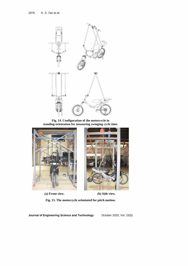
By measuring the inclination angle, and together with the known CG location along the x- and z-axis obtained in the earlier stage where the motorcycle was in the lying orientation, the CG location along the y-axis with the motorcycle midplane as datum can then be computed by applying the simple trigonometry relation. The secondary shaft was then locked horizontally to put the configuration ready for pitch oscillation, as presented in Fig. 14, and the real arrangement as shown in Fig. 15.
The motorcycle was then put in oscillation through the secondary shaft as shown in Fig. 16 and the cycle time corresponding to pitch motion for the motorcycle-fixture system is clocked. Again, the inertial effects of the fixture that are oscillated together, as shown in Fig. 17, has to be removed and the rotational inertia of the motorcycle alone about the same rotating axis, IPO, was calculated by deducting the value IPf from IPT. Thus, the rotational inertia of the motorcycle alone about its own CG, IP̅, was finally given by
IP̅=IPO-mMCdS2 (5)
where the subscript “S” notates standing orientation and the respective variables for the measurements are as illustrated in Fig. 16.
2976 K. S. Tan et al.
Journal of Engineering Science and Technology October 2020, Vol. 15(5)
Fig. 14. Configuration of the motorcycle in
standing orientation for measuring swinging cycle time.
(a) Front view. (b) Side view.
Fig. 15. The motorcycle orientated for pitch motion.

Method of Measurement for Inertial Properties of Powered Two-wheelers . . . . 2977
Journal of Engineering Science and Technology October 2020, Vol. 15(5)
Fig. 16. Definition of the variables used in calculating the pitch inertia.
(a) Isometric view. (b) Side view.
Fig. 17. Configuration of the fixtures for pitch motion in standing orientation.
Up to this stage, the inertial data required have been completely measured. However, it is worth to note that the oscillation of the motorcycle via the main shaft, as shown in Fig. 18, is indeed also a roll motion. In other words, an additional rotational inertia with respect to the roll motion can be obtained, notated with an additional prime symbol as IRT
' , of which can be used to cross-check with the MMI value that had previously determined with the motorcycle configured in the lying orientation. Again, there are inertial effects attributed to the fixture, IRf
' , as depicted in Fig. 19 that need to be excluded to obtain IRO
' . This additional roll inertia IR̅T' is
given by
IRT' = �TRT
'
2π�
2mRT
' glRT' (6)

2978 K. S. Tan et al.
Journal of Engineering Science and Technology October 2020, Vol. 15(5)
Finally, the roll inertia of a motorcycle alone about its own CG with the motorcycle configured in standing orientation, IR̅
' , is calculated from
IR̅' =IRO
' -mMCdS2 (7)
Fig. 18. Definition of the variables used for calculating the roll inertia with the motorcycle in standing orientation.
(a) Isometric view. (b) Side view.
Fig. 19. The fixture configuration for roll motion in standing orientation.
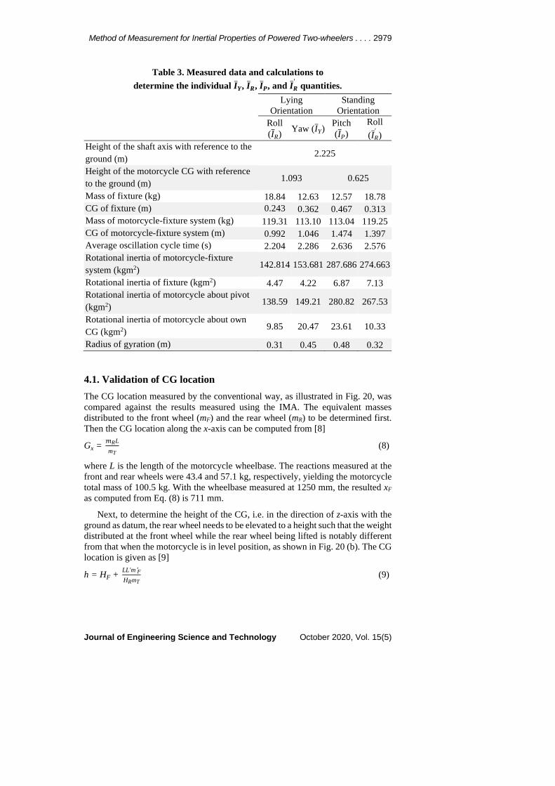
4. Results and Discussion The measurements and the resulted inertial properties calculated from the corresponding formulae are as tabulated in Table 3.
Method of Measurement for Inertial Properties of Powered Two-wheelers . . . . 2979
Journal of Engineering Science and Technology October 2020, Vol. 15(5)
Table 3. Measured data and calculations to determine the individual I̅Y, I̅R, I̅P, and I̅R
' quantities.
Lying Orientation
Standing Orientation
Roll (IR̅) Yaw (IY̅) Pitch
(IP̅) Roll (IR̅
' ) Height of the shaft axis with reference to the ground (m) 2.225
Height of the motorcycle CG with reference to the ground (m) 1.093 0.625
Mass of fixture (kg) 18.84 12.63 12.57 18.78 CG of fixture (m) 0.243 0.362 0.467 0.313 Mass of motorcycle-fixture system (kg) 119.31 113.10 113.04 119.25 CG of motorcycle-fixture system (m) 0.992 1.046 1.474 1.397 Average oscillation cycle time (s) 2.204 2.286 2.636 2.576 Rotational inertia of motorcycle-fixture system (kgm2) 142.814 153.681 287.686 274.663
Rotational inertia of fixture (kgm2) 4.47 4.22 6.87 7.13 Rotational inertia of motorcycle about pivot (kgm2) 138.59 149.21 280.82 267.53
Rotational inertia of motorcycle about own CG (kgm2) 9.85 20.47 23.61 10.33
Radius of gyration (m) 0.31 0.45 0.48 0.32
4.1. Validation of CG location The CG location measured by the conventional way, as illustrated in Fig. 20, was compared against the results measured using the IMA. The equivalent masses distributed to the front wheel (mF) and the rear wheel (mR) to be determined first. Then the CG location along the x-axis can be computed from [8]
Gx = 𝑚𝑚RLmT
(8)
where L is the length of the motorcycle wheelbase. The reactions measured at the front and rear wheels were 43.4 and 57.1 kg, respectively, yielding the motorcycle total mass of 100.5 kg. With the wheelbase measured at 1250 mm, the resulted xF as computed from Eq. (8) is 711 mm.
Next, to determine the height of the CG, i.e. in the direction of z-axis with the ground as datum, the rear wheel needs to be elevated to a height such that the weight distributed at the front wheel while the rear wheel being lifted is notably different from that when the motorcycle is in level position, as shown in Fig. 20 (b). The CG location is given as [9]
h = HF + LL'm'FHRmT
(9)

2980 K. S. Tan et al.
Journal of Engineering Science and Technology October 2020, Vol. 15(5)
With the lifted rear wheel, the reaction at the front wheel was increased to 51.8 kg. Thus, the height of the CG as calculated by Eq. (9) is 165 mm, measured from the front axle.
(a) Motorcycle in level orientation b) With the rear wheel elevated
Fig. 20.3 Measuring the front wheel reaction.
Comparisons of the CG locations obtained using the IMA and the conventional method are summarised in Table 4. The maximum deviations are found to be within 6%. However, if the ground is taken as a reference, this deviation is lowered to 2.2%. Thus, it is suggested that the IMA and the associated measurement technique is capable of locating the CG with reasonable accuracy.
Table 4. The respective CG locations measured by the conventional and IMA methods.
CG Measurement Method Deviation (%) IMA Conventional Gx 690 711 -2.95 Gy - - - Gz 155 165 -5.83
4.2. Validation of mass moment of inertia As seen earlier in the respective sections, the measuring procedures yielded two different MMI values with respect to each of the roll motions, firstly with the motorcycle in the lying and secondly in the standing configurations. This is indeed is useful to serve as a cross-check on the measured results. From the measuring procedures performed, the two values obtained for lying and standing orientations are 9.85 and 10.33 kgm2, respectively, as summarised in Table 3. With the deviation of 2.4%, it is reasonable to consider that the measured MMI values are well agreed to each other, thus demonstrated the reliability and consistency of the measuring method.
It was highlighted in [28] that the representation of dynamics of a motorcycle, particularly the straight line stability characteristics, were generally not sensitive to the changes of motorcycle inertial parameters with discrepancy allowance for as much as 20%. But there was an exception for yaw inertia, possibly due to the much greater degree of freedom about the steering axis compared to pitch and roll motions. The resulted discrepancies from the present measurement method are

Method of Measurement for Inertial Properties of Powered Two-wheelers . . . . 2981
Journal of Engineering Science and Technology October 2020, Vol. 15(5)
substantially within the range of the allowance and thus it is sufficient to determine the CG and MMI of a typical motorcycle with reasonable accuracy.
Besides, it would be more advantageous to measure the inertial parameters directly in the form of a complete motorcycle, instead of dismantling it into various individual subassemblies or components and then to measure and sum each of them to obtain the corresponding values of a whole motorcycle. This is mainly because the subassemblies and components are usually having much more complex form which are impractical to be measured and as the mass reduces, it would be more susceptible to measurement errors. Consequently, the accumulated individual errors would then lead to larger discrepancies. Thus, the direct measurement method indeed provides a better approach to account for complex geometries and the associated inertial parameters and thus minimises erroneous measurements.
4.3. Verification Using Standard Blocks A standard composite block composed of simple prisms, such as of rectangular and circular shapes can be used for the purpose of performance verification and also for calibrating the IMA, since their inertial properties can be accurately calculated in a simple way. The photograph and the engineering drawing of the fabricated composite block used here, which weighed 40.3 kg, is shown in Fig. 21. The lateral brackets with a hole provide the attachment part for the chain segment to hook on. Results of the calibration using the composite block is presented in Table 5.
(a) Real part (b) Engineering drawing
Fig. 21. The composite block for the calibration of IMA.
Table 5. The calibration results using the composite block.
Axis I (kgm-2) Deviation (%) Analytical Measured Ixx 0.750 0. 773 3.1 Iyy 0.113 0. 120 5.3 Izz 0.678 0. 692 2.1
5. Conclusions The IMA has been fabricated, commissioned and tested successfully using the associated measuring technique to measure the translational and rotational inertia of a typical motorcycle as a test object. In spite of the existence of these source of deviations, the newly established method using the IMA was capable to determine both the CG location and rotational inertia of a motorcycle with respect to three

2982 K. S. Tan et al.
Journal of Engineering Science and Technology October 2020, Vol. 15(5)
orthogonal axes, with acceptable results and accuracies based on the performance evaluations. Moreover, the measurement methodology allows both the CG location and MMI for a test object to be determined using only one single tool in a continuous operation with a few standardized routine steps.
The functionality of the apparatus and the measuring technique is generally not limited to the specific motorcycle model such as the one used in the current study. It can also be applied to its variants which are not significantly different in sizes and geometric designs yet having the common features, namely handles, forks and back seat rest bar, that serve as attachments for the suspended arms. The variants include the typical motorcycles having an engine capacity of 125±25 cc, a wet mass of about 100±10 kg and a wheelbase of about 1250±50 mm.
Acknowledgement The authors wish to acknowledge the financial support from Ministry of Education Malaysia under the Fundamental Research Grant Scheme (FRGS) (Grant No. FRGS/FASA-1-2012//TK01/UPNM/03/3).
Nomenclatures dL, dS Perpendicular distance of the centre of gravity of the
motorcycle from the longitudinal axis of the shaft for lying, and standing orientation, m
Gx Location of centre of gravity along x-axis with reference to the front axle
Gy Location of centre of gravity along y-axis with reference to the front axle
Gz Location of centre of gravity along z-axis with reference to the front axle
g Gravitational acceleration, ms-2 HO Height of the longitudinal axis of the shaft from the ground, m HF, HR Height of the front, and rear axle from the ground, m h Height of the centre of gravity of motorcycle from the ground,
m hL, hS Height of the centre of gravity of the motorcycle from the
ground for lying, standing orientation, m IPf, IRf, IYf Rotational inertia of the fixture with respect to the motorcycle
pitch, roll, and yaw motion, kgm2 IPO, IRO, IYO Pitch, roll, and yaw moment of inertia of the motorcycle alone
about the hanging axis, kgm2 IPT, IRT, IYT Pitch, roll, and yaw moment of inertia of the assembly of the
motorcycle and fixture about the hanging axis, kgm2 IP̅, IR̅, IY̅ Pitch, roll, and yaw moment of inertia of the motorcycle alone
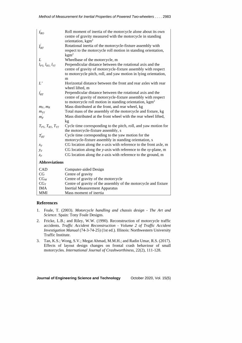
about its own centre of gravity, kgm2 IR' Roll moment of inertia of the motorcycle alone about its own
centre of gravity measured with the motorcycle in standing orientation, kgm2
IRf' Rotational inertial of the fixture with respect to the motorcycle
roll motion for standing orientation, kgm2
Method of Measurement for Inertial Properties of Powered Two-wheelers . . . . 2983
Journal of Engineering Science and Technology October 2020, Vol. 15(5)
IRO' Roll moment of inertia of the motorcycle alone about its own
centre of gravity measured with the motorcycle in standing orientation, kgm2
IR̅T' Rotational inertia of the motorcycle-fixture assembly with
respect to the motorcycle roll motion in standing orientation, kgm2
L Wheelbase of the motorcycle, m lPT, lRT, lYT Perpendicular distance between the rotational axis and the
centre of gravity of motorcycle-fixture assembly with respect to motorcycle pitch, roll, and yaw motion in lying orientation, m
L’ Horizontal distance between the front and rear axles with rear wheel lifted, m
lRT' Perpendicular distance between the rotational axis and the
centre of gravity of motorcycle-fixture assembly with respect to motorcycle roll motion in standing orientation, kgm2
mF, mR Mass distributed at the front, and rear wheel, kg mYT Total mass of the assembly of the motorcycle and fixture, kg mF
' Mass distributed at the front wheel with the rear wheel lifted, kg
TPT, TRT, TYT Cycle time corresponding to the pitch, roll, and yaw motion for the motorcycle-fixture assembly, s
TRT' Cycle time corresponding to the yaw motion for the
motorcycle-fixture assembly in standing orientation, s xF CG location along the x-axis with reference to the front axle, m yF CG location along the y-axis with reference to the xy-plane, m zF CG location along the z-axis with reference to the ground, m
Abbreviations
CAD Computer-aided Design CG Centre of gravity CGM Centre of gravity of the motorcycle CGT Centre of gravity of the assembly of the motorcycle and fixture IMA Inertial Measurement Apparatus MMI Mass moment of inertia
References 1. Foale, T. (2003). Motorcycle handling and chassis design - The Art and
Science. Spain: Tony Foale Designs. 2. Fricke, L.B.; and Riley, W.W. (1990). Reconstruction of motorcycle traffic
accidents. Traffic Accident Reconstruction - Volume 2 of Traffic Accident Investigation Manual (74-3-74-25) (1st ed.). Illinois: Northwestern University Traffic Institute.
3. Tan, K.S.; Wong, S.V.; Megat Ahmad, M.M.H.; and Radin Umar, R.S. (2017). Effects of layout design changes on frontal crash behaviour of small motorcycles. International Journal of Crashworthiness, 22(2), 111-128.

2984 K. S. Tan et al.
Journal of Engineering Science and Technology October 2020, Vol. 15(5)
4. Meijaard, J.P.; and Popov, A.A. (2006). Numerical continuation of solutions and bifurcation analysis in multibody systems applied to motorcycle dynamics. Nonlinear Dynamics, 43, 97-116.
5. International Organization for Standardization. (2005). Motorcycle - Measurement Method for Location of Centre of Gravity (ISO 9130: 2005).
6. International Organization for Standardization. (2008). Motorcycle - Measurement methods for moment of inertia (ISO 9129: 2008).
7. Nieboer, J.J.; Wismans, J.; Versmissen, A.C.M.; van Slagmaat, M.T.P.; Kurawaki, I.; and Ohara, N. (1993). Motorcycle crash test modelling. Proceedings of the 37th Stapp Car Crash Conference. Texas, US, 273-288.
8. Metz, L.; Akouris, C.; Agney, C.; and Clark, M. (1990). Moments of inertia of mounted and unmounted passenger car and motorcycle tires. SAE Transactions Section 6, 99, 1079-1085.
9. Chung, J.E.; and Lee, S. (2016). Measurement of inertia of turbocharger rotor in a passenger vehicle. Transactions of the Korean Society of Automotive Engineers, 24(1), 33-38.
10. Hou, Z.-c.; Lv, Y.; Lao, Y.-x.; and Liu, D. (2009). A new trifilar pendulum approach to identify all inertia parameters of a rigid body or assembly. Mechanism and Machine Theory, 44(6), 1270-1280.
11. Hejtmánek, P.; Blaťák, O.; Kucera, P.; Portes, P.; and Vančura, J. (2013). Measuring the yaw moment of inertia of a vehicle. Journal of Middle European Construction and Design of Cars, 11(1), 16-22.
12. Hinrichsen, Peter. (2014). Bifilar suspension measurement of boat inertia parameters. Journal of Sailboat Technology, 3(1), 1-37.
13. Halder, A.; Agarwal, V.; Garhwal, R.; and Sinha, M. (2008). Determination of inertial characteristics of a high wing unmanned air vehicle. Journal of Institute of Engineers (India), 89, 3-8.
14. Jardin, M.R.; and Mueller, E.R. (2009). Optimized measurements of unmanned-air-vehicle mass moment of inertia with a bifilar pendulum. Journal of Aircraft, 46, 63-75.
15. Krznar, M.; Kotarski, D.; Piljek, P; and Pavkoviæ, D. (2018). On-line inertia measurement of unmanned aerial vehicles using on-board sensors and bifilar pendulum. Interdisciplinary Description of Complex Systems, 16(1), 149-161.
16. Green, M.W. (1927). Measurement of the Moments of Inertia of full scale Aircraft. Technical Notes No. 265, National Advisory Committee for Aeronautics, Langley Memorial Aeronautical Laboratory, Washington, 1-18.
17. Fennell, L.J. (1967). Measurement of the Moments of Inertia of a Handley Page HP115 Aircraft. Paper No. 907, Aeronautical Research Council, Her Majesty`s Stationary Office.
18. Shakoori, A.; Betin, A.V.; and Betin, D.A. (2016). Comparison of three methods to determine the inertial properties of free-flying dynamically similar models. Journal of Engineering Science and Technology (JESTEC), 11(10), 1360-1372.
19. Du Bois, J.L.; Lieven, N.A.J.; and Adhikari, S. (2009). Error analysis in trifilar inertia measurements. Experimental Mechanics, 49, 533-540.

Method of Measurement for Inertial Properties of Powered Two-wheelers . . . . 2985
Journal of Engineering Science and Technology October 2020, Vol. 15(5)
20. Hinrichsen, P.F. (2018). Bi and trifilar suspension centering correction. Meccanica, 53, 21-32.
21. Genta, G.; and Delprete, C. (1994) Some considerations on the experimental determination of moments of inertia. Meccanica, 29:125-141.
22. Lyons, D. (2002). Obtaining optimal results with filar pendulums for moment of inertia measurements. 61th Annual Conference of Society of Allied Weight Engineers, Virginia, US.
23. Cossalter, V.; Doria, A.; and Mitolo, L. (2002). Inertial and modal properties of racing motorcycles, SAE Technical Paper 2002-01-3347.
24. Monk, M.W. (1993). Centre of Gravity and Moments of Inertia Device. United States Patent, US 5177998 A.
25. Andreatta, D.A.; Heydinger, G.J.; Bixel, R.A.; Sidhu, A.; Kurec, A.; Igor Baseski, I.; and Skorupa, T. (2014). The Vehicle Inertia Parameter Evaluation Rig II - A device for measuring inertia parameters of all sizes of military vehicles. NDIA Ground Vehicle Systems Engineering and Technology Symposium, Michigan, US.
26. Brabec, P. (2017). Measurements of mass moments of inertia of multi-body systems. Proceedings of the 7th International Conference on Mechanics and Materials in Design, Algarve, Portugal, 373-380.
27. Zhu, T.; Zhang, F.; Li, J.; Li, F.; and Zong, C. (2018). Development identification method of inertia properties for heavy truck. MATEC Web of Conferences, 153.
28. Sharp (1971). The stability and control of motorcycles. Journal of Mechanical Sciences, 13(5), 316-329.