design and cost estimation of a stand-alone pv system to … · · 2015-05-31production has an...
TRANSCRIPT
Journal of Multidisciplinary Engineering Science and Technology (JMEST)
ISSN: 3159-0040
Vol. 2 Issue 5, May - 2015
www.jmest.org
JMESTN42350791 1241
Design and Cost Estimation of a Stand-Alone PV System to Electrify Radar and Portable
Water Desalination Set Dr. Ahmed M. Atalla
1 , Dr. M. A. El-Dessouki
1 , Eng. Mina magdyAziz
2
[email protected], [email protected], [email protected] Faculty of Engineering, Electrical Power & Machines Department, Ain Shams University, Cairo, Egypt
1
Egypro FME company 4th District, Zahraa El Maadi ,New Maadi, Cairo,Egypt. 114312
Abstract—In this paper a standalone
Photovoltaic system is designed to supply a combined load of a radar system and water desalination near a salt water of sea. The electricity can be produced by using PV system and store energy in chemical batteries or using fuel cells. This is done using battery charger and reuse it during night and cloudy days. The electrical load data of a typical radar and water desalination are taken into consideration during the design steps. The system is very effective to stand about 4 days with its total power capacity. A potable unit desalination of water is used to give pure water for at least 7 persons. A model is built using Matlab/Simulink to measure its stability with its components. The results of the study encouraged the use of the PV systems in military purposes in regions lacking fresh water sources in Egypt such as Sinai. Finally, the estimated cost of the designed stand-alone PV system with batteries and fuel cell is discussed.
Keywords—Remote area electrification, PV array, storage battery, battery charge controller, inverter, radar, desalination, fuel cell
I. INTRODUCTION
Recently, using Photovoltaic (PV) energy production has an increasing demand in our society due to the lack of fossil of fuel. It is reported [1] that the fossil fuel with start to end at 2088. PV has become an essential part of the future energy generation since it has no pollution, free availability and high reliability. In developing countries, the use of PV is very important in remote areas in which the supplying of fuel is very difficult.
A review about the recent years achievements occurred in the field of desalination by renewable energies has been made [2] taking into account the technologies and economics. The review includes water sources, demand, availability of potable water and purification methods. The authors made a comparative study between different renewable energy technologies and concluded that the problem is the optimum economic design for remote regions.
A complete design and cost analysis of the PV system electrifying a remote isolated household has been presented in [3]. The authors show that the PV is suitable for long-term investments for low prices
and high efficiencies of the PV systems. The authors in [4] present recommended design practices for stand-alone photovoltaic (PV) systems. Sixteen specific examples of PV systems, designed for different applications, are presented. These include warning signals, lighting, refrigeration, communications, residential, water pumping, remote sensing.
Water desalination has been analyzed in [4,5,6]. In [4] an illustration about desalination process, how it can be produced from seawater, energy consumption, experiments and techniques is presented. The key objective of the work in [5] involves the optimization of the variables involved in the pre-treatment process of a seawater reverse osmosis plant which would lead to an increase in the membrane life by reducing solids content of the raw water. Experiments were carried out to ensure maximum total solids reduction. A combination of sedimentation, disk and ultra-filtration processes was tested. A project has been built [6] for water purification. It gives information about the product and how it operates by using photovoltaic panel to give the specification of the product as the pure output water.
Radar has been discussed in some research works [8-12]. A brief explanation about the term radar, history of radar and its application in all fields (i.e. civil and military applications) is presented in [8]. It talks about radar principles, radar engineering and radar signal processing. The Radar Navigation and Maneuvering Board Manual are illustrated [9] which contain information on the fundamentals of shipboard radar, radar operation, collision voidance, navigation by radar, and a description of vessel traffic systems in US waters. The authors in [10,11] define range, bearing, and altitude as they relate to a radar system. They discussed how pulse width, peak power, and beam width affect radar performance. They used a block diagram to describe the basic functions, principles of operation, and interrelationships among basic units of radar. A brief explanation and specifications of a radar type AN/TPS-75, why it is designed, how it can be transported and its technology are illustrated in [12].
The work in [13] covers what the fuel cell is, history of fuel cells, its application, and direct methanol fuel cell and how the hydrogen will come from. Data sheet for a self-recharging fuel cell system are stated in [14].

Journal of Multidisciplinary Engineering Science and Technology (JMEST)
ISSN: 3159-0040
Vol. 2 Issue 5, May - 2015
www.jmest.org
JMESTN42350791 1242
They are designed to be a logistics-free backup power solution powered by renewable, to eliminate the need for refueling, reducing operating costs and expensive maintenance visits and saving both time and money. An online calculator that estimates the energy production and cost of energy of grid-connected photovoltaic (PV) systems is explained [15]. It allows homeowners, small building owners and manufacturers to develop expected estimates of the cost and performance of potential PV installations. The work in [16] gives data sheet of batteries which contain information about charging characteristic, table of performance, calculation of installation.
The use of renewable energy in military purposes is very limited. It is used in providing energy just only for camps in urbane area in which the supplying of fuel is very difficult. Hence, this research work is directed to open the door to the use of solar cell for military services. Specially, in desert or behind enemies line or in zones that is very difficult to have fuel. Radar is important equipment in any army. Also pure water may be required for soldiers. The paper suggests a new solution for providing energy to a radar and purification set that may exist far from the electrical network.
II.FORMULATION OF THE PROBLE
The problem is how to design a portable PV system that may be used for military purposes. A combined load that consists of a radar and water desalination set is suggested. Firstly radar analysis is presented to choose a reasonable type with its specifications. Secondly the methodology of the selection of water desalination is discussed. After load estimation, the paper is directed to build a suitable design of PV set. Sizing PV array, batteries charger controller and the inverter. After that a simulation of the system as a whole is constructed via Matlab/Simulink. Then Analysis of harmonics is presented to illustrate the significance of their effect.
III. RADAR SELECTION
Radar can detect an object by transmitting pulses of radio waves that find the object and its location, altitude, and speed. The power of the transmitter is included in the radiated pulses and is called the PEAK POWER of the system [2]. A definite relationship exists between the average power dissipated over an extended period of time and the peak power developed during the pulse time. Other factors remaining constant, the longer the pulse length, the higher will be the average power; the longer the pulse repetition time, the lower will be the average power.
𝑎𝑣𝑒𝑟𝑎𝑔𝑒 𝑝𝑜𝑤𝑒𝑟
𝑝𝑒𝑎𝑘 𝑝𝑜𝑤𝑒𝑟 =
𝑝𝑢𝑙𝑠𝑒 𝑙𝑒𝑛𝑔𝑡ℎ
𝑝𝑢𝑙𝑠𝑒 𝑟𝑒𝑝𝑒𝑡𝑖𝑜𝑛 𝑡𝑖𝑚𝑒
High peak power is desirable to produce a strong echo over the maximum range of the equipment. The peak value of the power developed is dependent upon the interrelation between peak and average power, pulse length, and pulse repetition time, or duty cycle.
Pulse-modulated radar system includes six main components, as follows;
1. The power supply furnishes all AC and DC voltages necessary for the operation of the system components.
2. The modulator produces the synchronizing signals that trigger the transmitter the required number of times per second. It also triggers the indicator sweep and coordinates the other associated circuits.
3. The transmitter generates the radio-frequency energy in the form of short powerful pulses.
4. The antenna system takes the radio-frequency energy from the transmitter, receives any returning echoes and passes these echoes to the receiver.
5. The receiver amplifies the weak radio-frequency pulses (echoes) returned by a target and reproduces them as video pulses passed to the indicator.
6. The indicator produces a visual indication of the echo pulses in a manner that furnishes the desired information
Table 1 Different types of radars used in military
purposes [ 4,6,7,8 ]
Radar Name Average power
Peak power Pic
AN/TPS-75 4.7 KW 2.8 MW
IFF/SIF – Siemens
1990 100 W 2 KW
PAR 80 124 W 182 KW
AN TPS-25 40 W 43 KW
Table 1 shows data of different types of radars for military purposes. The comparison is done between power consumed (average and peak powers). In this paper the radar of type AN/TPS-25 [8] is chosen due to its small power consumed which makes it more effectively to be fed from photovoltaic in the suggested system. Tables (2) and (3) show radar specifications which include the power supply and the dissipation of power [11].
Journal of Multidisciplinary Engineering Science and Technology (JMEST)
ISSN: 3159-0040
Vol. 2 Issue 5, May - 2015
www.jmest.org
JMESTN42350791 1243
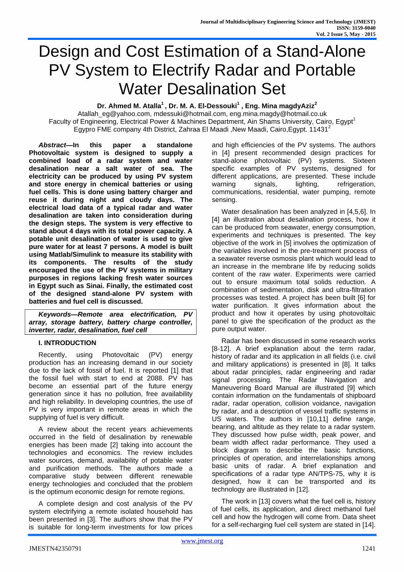
Table 2 Specifications of voltage source
Power source
Voltage 115±𝟓% 𝑨𝑪, Single
Phase
Frequency 400±𝟓% HZ
Wattage (less shelter) 1.17 KW
Wattage (with shelter) 1.515 KW
Power factor 0.955
Average current (less shelter)
10.2 A
Average current (with shelter)
13.75 A
Surge current (less shelter) 41.4 A
Surge current (with shelter ) 47.3 A
Table 3 Power dissipated in radar AN/TPS-25
Power dissipation
Receiver-transmitter 300 W
Modulator 200 W
Coordinator 275 W
Radar set control 75 W
Power supply 125 W
Shelter including (lights, fans and heaters)
345 W
IV. SELECTION OF DESALINATION PROCESS
Renewable energy systems is thought to be a viable solution to the water scarcity at remote areas characterized by lack of potable water and conventional energy sources like heat and electricity grid. Several renewable energy desalination pilot plants have been installed and the majority has been successfully operated for a number of years. Virtually, all of them are custom designed for specific locations and utilize solar, wind to produce fresh water.[11]
Operational data and experience from these plants can be utilized to achieve higher reliability and reduced cost [12]. A reverse osmosis water purification unit (ROWPU) is a portable, self-contained water plant which can provide pure water from any water source
There are many models in use by the United States and the Canadian Forces[12]. The water is pumped from its raw source into the reverse osmosis water purification unit module, where it is treated with a polymer to initiate coagulation. Next, it is run through a multi-media filter where it undergoes ion exchange. It is then pumped through a cartridge filter which is usually spiral-wound cotton. This process clarifies the water of any particles larger than 5 micrometres (0.00020 in) and eliminates almost all turbidity. The clarified water is then fed through a high-pressure piston pump into a series of vessels where it is subject to reverse osmosis. The product water is free of 90.00–99.98% of the raw water's total dissolved solids and by military standards, should
have no more than 1000–1500 parts per million by measure of electrical conductivity. It is then disinfected with chlorine and stored for later use.
Specification [7]:
Produce Fresh Water: 6.25 GPH (23 LPH) / 8.3 GPH (31.5 LPH)
Treat Water: Seawater or Brackish / Seawater or Brackish
Power Consumption: 108 Watts @ 24v DC Feed water recovery: 7% / 10% Salt rejection: 99.4% Minimum Feed Flow: 1.5 GPM (5.65 LPM) Feed Pump: Shurflo 9300 high head submersible
well pump Membranes 2.5"x21" Seawater RO: 1 Each System Weight & Dimensions: 32" L x 21"W x
15.5" H - Weight 75 Lbs System Operation Voltage: 24v DC
V. SELECTION OF FUEL CELL [7]
Acta power is a self-recharging fuel cell system and a backup power supply. It eliminates the need for refueling. It has low operating and maintenance costs. It provides clean energy and does not need batteries and gensets thus eliminating fuel price uncertainty. Its characteristics are:
1. Self-recharging system generating its fuel from water. Its rating from 2 to 4 kW power output.
2.It can be connected with grid in both on and off applications.
3. It Works with conventional grid and with renewables (solar, wind).
4. Flexible, complete remote management and control: from dry contacts to IP based protocol Human machine interface with over 30 manageable parameters
5. Efficient, with the lowest and highest H2 consumption and production efficiency, table(4)
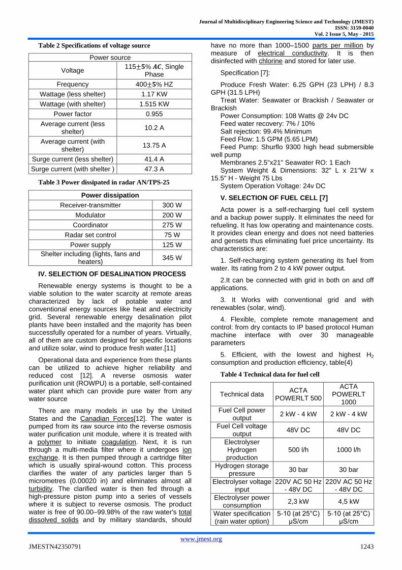
Table 4 Technical data for fuel cell
Technical data ACTA
POWERLT 500
ACTA POWERLT
1000
Fuel Cell power output
2 kW - 4 kW 2 kW - 4 kW
Fuel Cell voltage output
48V DC 48V DC
Electrolyser Hydrogen production
500 l/h 1000 l/h
Hydrogen storage pressure
30 bar 30 bar
Electrolyser voltage input
220V AC 50 Hz - 48V DC
220V AC 50 Hz - 48V DC
Electrolyser power consumption
2,3 kW 4,5 kW
Water specification (rain water option)
5-10 (at 25°C) µS/cm
5-10 (at 25°C) µS/cm
Journal of Multidisciplinary Engineering Science and Technology (JMEST)
ISSN: 3159-0040
Vol. 2 Issue 5, May - 2015
www.jmest.org
JMESTN42350791 1244
Communication & Alarms: remote monitoring and
control
MODBUS over RS232/Ethernet,
SMS alert (GSM-GPRS)
MODBUS over RS232/Ethernet,
SMS alert (GSM-GPRS)
Operating temperature
Table(4) Typical data of fuel cell
-5 to +45°C -5 to +45°C
Cabinet dimensions (WxLxH)
894x894x2300 mm
894x894x2300 mm
VI. PV SYSTEM DESIGN
A. Site meteorological data
To know what is performance of a PV system in a site, it must to collect the meteorological or environmental data for the site location under consideration. In this application the data is based on NREL (National renewable energy laboratory)[16] to have these data. The monthly average daily solar radiation data incident on PV array tilted by the latitude angle 20 of the site is shown in table5. The table shows that solar energy incident in the considered site is very high especially during the summer months, where it exceeds 7 kWh/m2 /day on tilted plan.
Table 5 Distribution of solar radiation in Egypt
around a year based on NREL[16]
Month Jan Feb Mar Apr. May June July Aug Sep Oct Nov Dec Ave.
Solar Radiation ( kWh /
m2
/ day)
3.68 4.79 5.48 6.31 6.69 7.31 7.25 6.86 6.59 4.9 4.08 3.8 5.66
B. Average load demand [16,17]
For a total load of 1.6 kW across a day the total energy demand across a day can be given by:
EL=1.6 KW*24=38.4 Kwh
C. Sizing PV array
sizing pv array is calculated using this equation [16-17]:
PV area=EL
𝐺A ∗ 𝜂 PV∗𝑇𝐶𝐹∗ 𝜂out (1)
Where
Gav average solar energy input per day
TCF temperature correction factor
η PV PV efficiency
ηout battery efficiency (ηB) * inverter efficiency(ηInv)
By assuming that the cell temperature reach 60 oC
in the field, so the temperature correction factor (TCF) will be 0.8 as in [3]. Assuming ηPV = 12% and η out = 0.85*0.9 = 0.765. Thus, using Eq. (1) the PV area is 92.3 m
2
The PV peak power at peak solar insolation (PSI) of 1000 W/m
2, is thus given by [17]:
PV Peak power = PV area * PSI * 𝜂 PV (2)
=92.3*1000*0.12=11076 Wp
Peak power of module: 270 Wp
Peak current: 7.8 A
Peak voltage: 36 V
So the total number of modules needed is 40 modules. This number is estimated we will use model of PV on Matlab to choose the bus voltage in which the DC system current must kept below 100 amp according to [18].so we get that at 4 modules in series and 10 parallel strings, the current will below 80 ampere and the output voltage is 140 v
D. Batteries sizing:
The batteries capacity can be calculated according to the following relation [17]:
𝑁c∗𝐸L
𝐷𝑂𝐷∗𝜂OUT (3)
In which
𝑁c Largest number of continuous cloudy days of the site
𝐷𝑂𝐷 Maximum permissible depth of discharge of the battery
The largest number of continuous cloudy days NC is about 4 days according to [17]. Thus, for a maximum depth of discharge for the battery (DOD) of 0.8 [17], the storage capacity becomes 250 KWh, as shown in Eq.3. If a single battery (Vision 6FM230D) of 12 V and 230 Ah is used, then the total batteries needed are 90 batteries so
No. of batteries in series are 10
No.of parallel stings are 90 /10=9
VII. DESIGN OF BATTERY CHARGER CONTROLLER
The battery charger controller is required to safety charge the batteries and to maintain longer lifetime for them. It has to be capable of carrying the short circuit current of the PV array. According to battery data sheet [19], to achieve nominal performance characteristics, it is recommended to adjust this value to suit the ambient temperature, as indicated in table6:
Table 6 Float charge voltage for batteries
Temperature Float charge voltage
0 °𝑐 2.31-2.36
10 °𝑐 2.28-2.33
20 °𝑐 2.25-2.3
25 °𝑐 2.23-2.28
30 °𝑐 2.22-2.27
35 °𝑐 2.2-2.25
To operate this radar in desert the charging voltage for batteries is
= 2.25*6*10=135 V
Journal of Multidisciplinary Engineering Science and Technology (JMEST)
ISSN: 3159-0040
Vol. 2 Issue 5, May - 2015
www.jmest.org
JMESTN42350791 1245
And due to losses at the system the charging voltage will be 140 v
The nominal voltage for battery voltage is 12*10=120 V
Thus, in this case, it can be chosen to handle 80 A( i.e 2*40 Amp).
VIII. THE INVERTER DESIGN
According to radar manufacturer data [ ]: the rated voltage is 115 AC and Frequency is 400 HZ and radar can stand surge current about 48 A so
Radar rating =48*115≈ 6 𝐾𝑉𝐴
The available inverter in market operates at input voltage 28 VDC output: 400Hz, 115 AC, the converter must be down from 140 V to 28 V as input to inverter
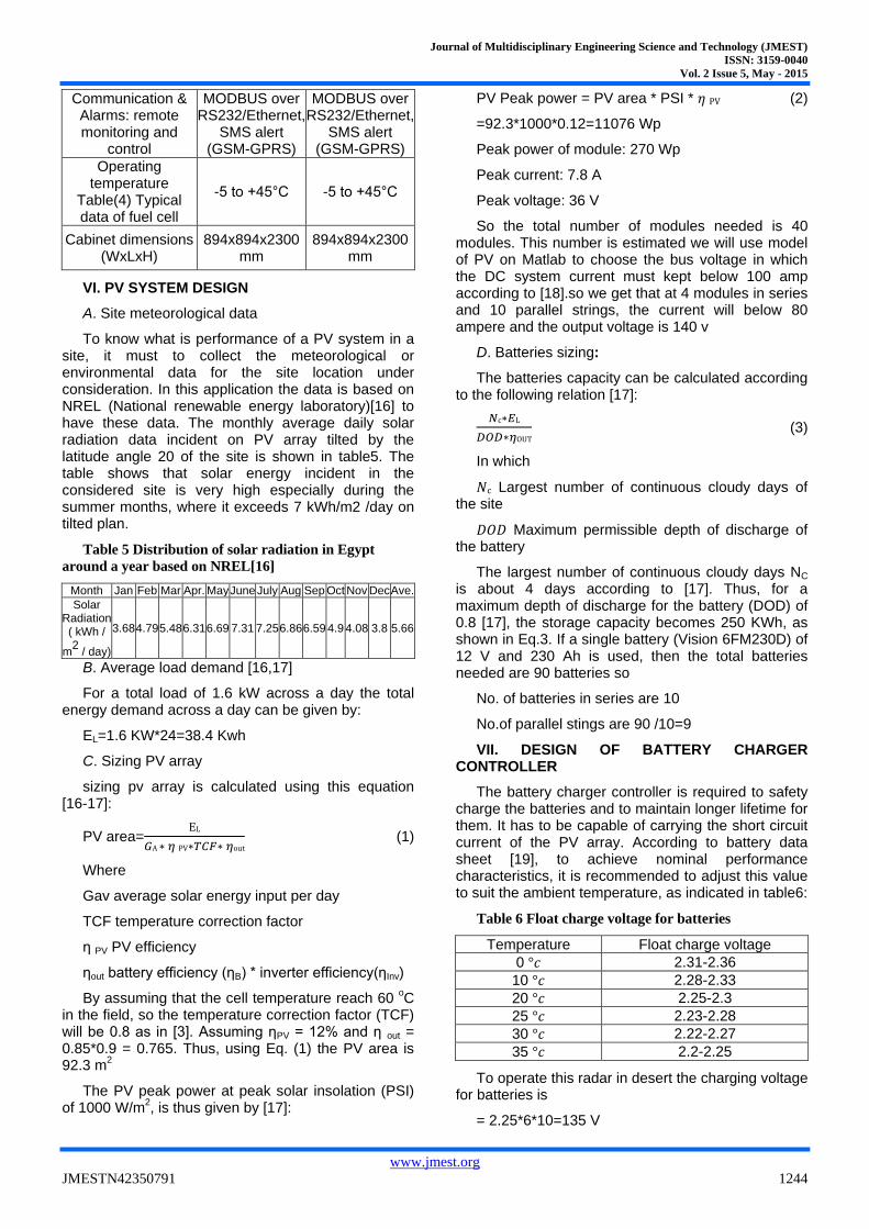
VIII. SIMULATION OF THE SYSTEM USING MATLAB/ SIMULINK
The model in Fig.1 illustrates that all components of system. They are PV array model, boost converter and LC filter. The converter is boosting the voltage and keeps it to enter inverter stage in which dc changes to ac. The filter removes harmonics which go to radar load. Some measure blocks are used to measure THD for voltage and current.
Figure 1 PV model for standalone system of radar
IX. RESULTS AND DISCUSSION
Two cases are considered: 1st case the PV system without Batteries, and
2nd
case the PV system with Batteries in which we assume the SOC is 80%
A. PV model results
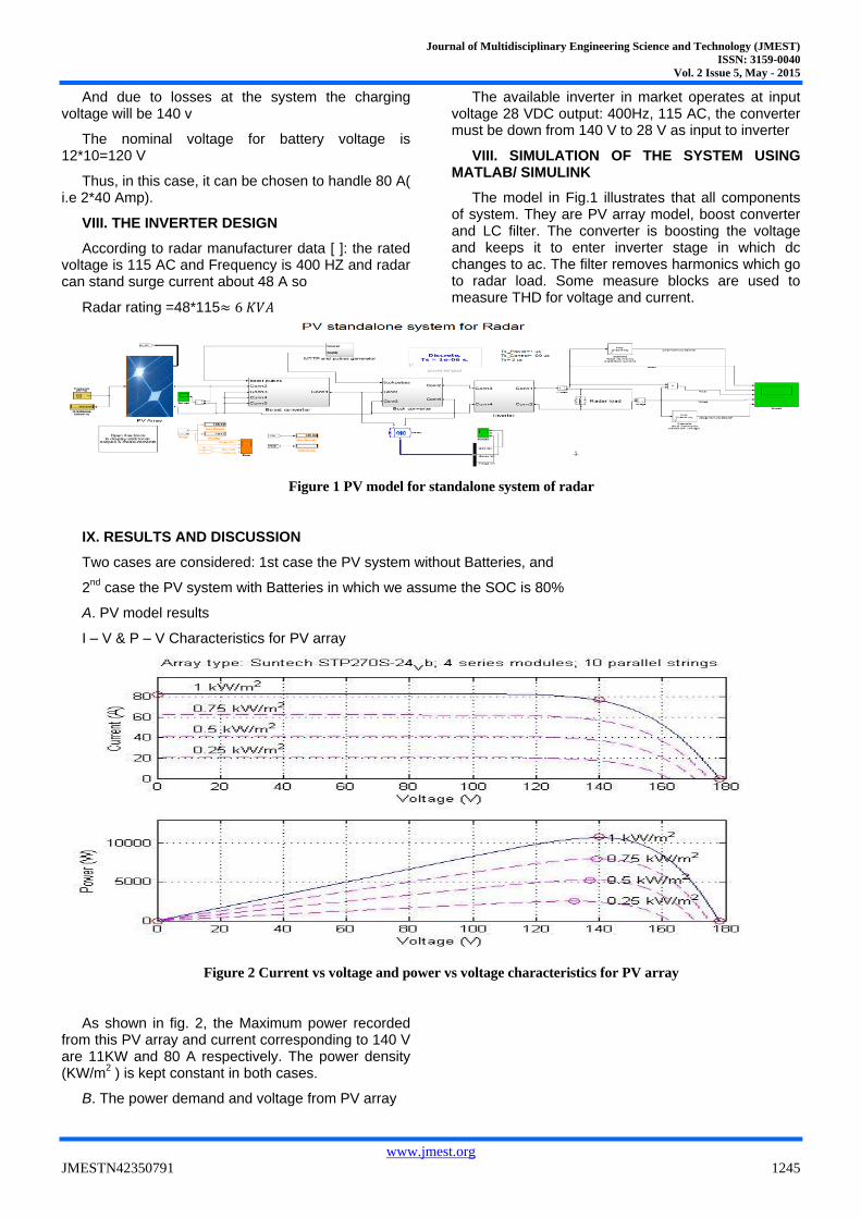
I – V & P – V Characteristics for PV array
Figure 2 Current vs voltage and power vs voltage characteristics for PV array
As shown in fig. 2, the Maximum power recorded from this PV array and current corresponding to 140 V are 11KW and 80 A respectively. The power density (KW/m
2 ) is kept constant in both cases.
B. The power demand and voltage from PV array
Journal of Multidisciplinary Engineering Science and Technology (JMEST)
ISSN: 3159-0040
Vol. 2 Issue 5, May - 2015
www.jmest.org
JMESTN42350791 1246
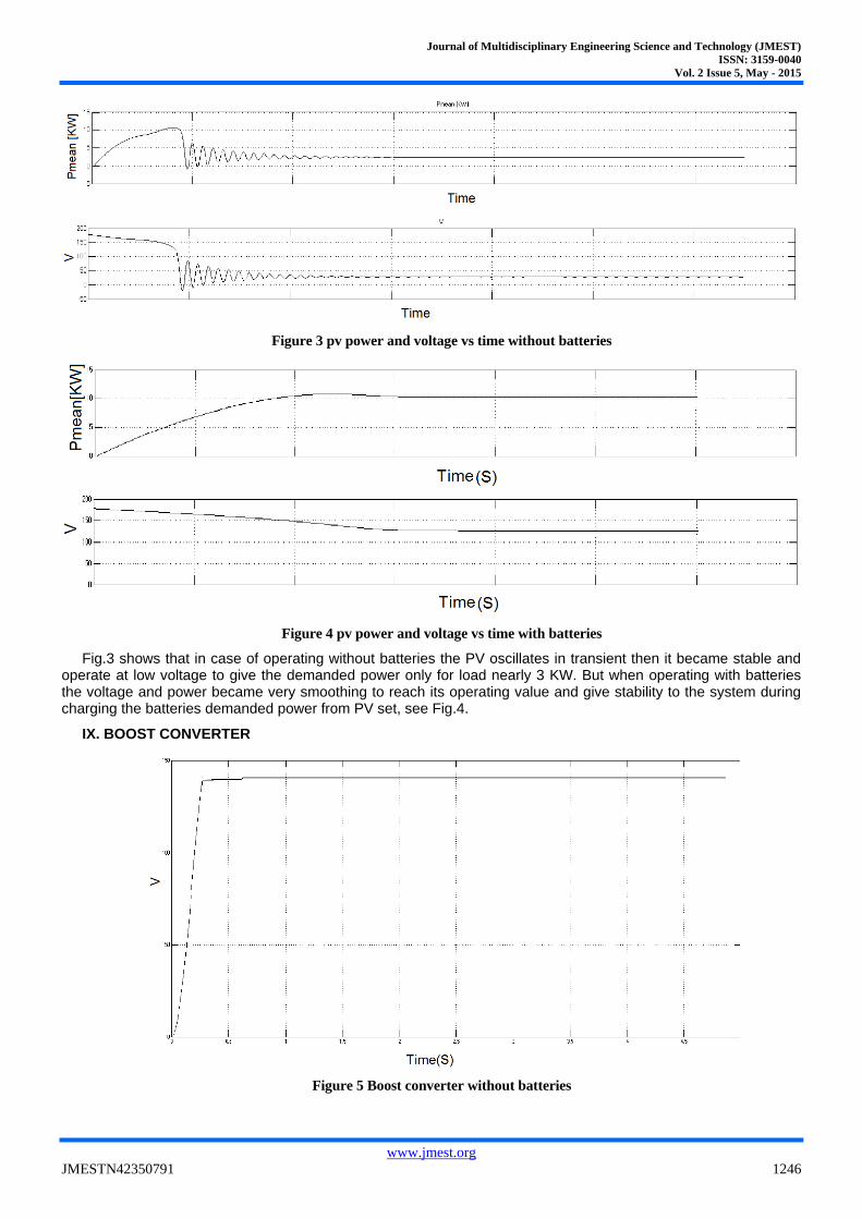
Figure 3 pv power and voltage vs time without batteries
Figure 4 pv power and voltage vs time with batteries
Fig.3 shows that in case of operating without batteries the PV oscillates in transient then it became stable and operate at low voltage to give the demanded power only for load nearly 3 KW. But when operating with batteries the voltage and power became very smoothing to reach its operating value and give stability to the system during charging the batteries demanded power from PV set, see Fig.4.
IX. BOOST CONVERTER
Figure 5 Boost converter without batteries
Journal of Multidisciplinary Engineering Science and Technology (JMEST)
ISSN: 3159-0040
Vol. 2 Issue 5, May - 2015
www.jmest.org
JMESTN42350791 1247
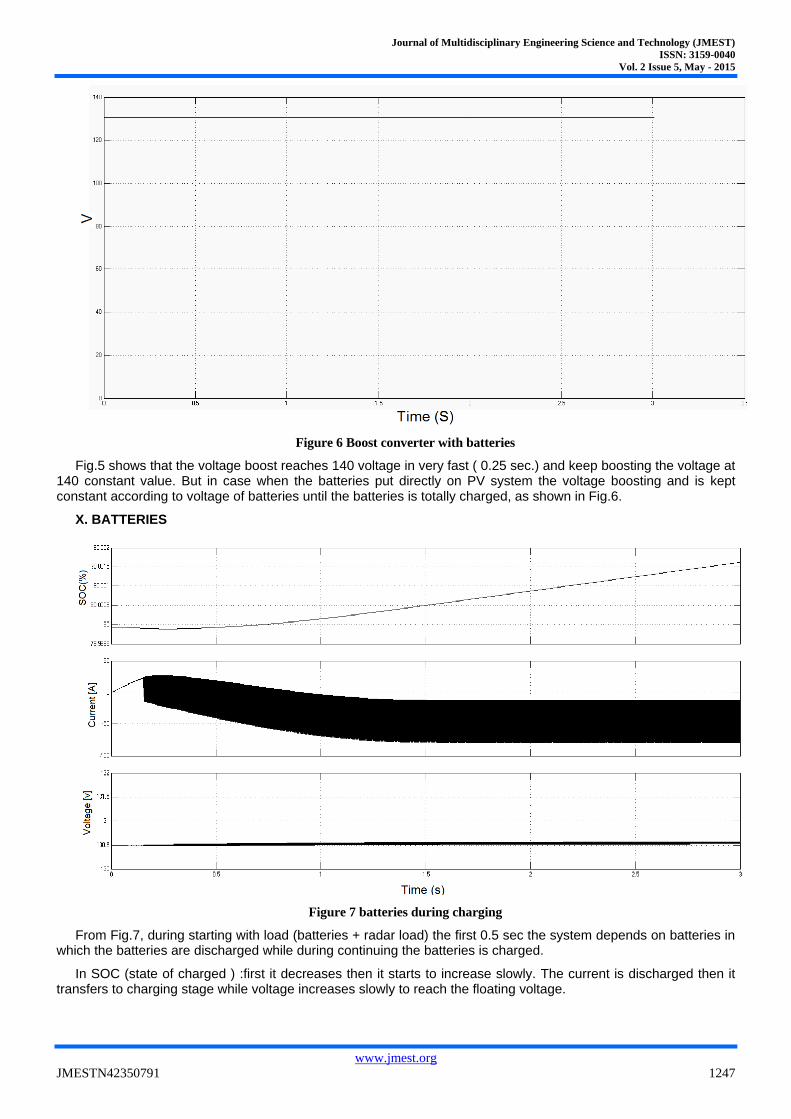
Figure 6 Boost converter with batteries
Fig.5 shows that the voltage boost reaches 140 voltage in very fast ( 0.25 sec.) and keep boosting the voltage at 140 constant value. But in case when the batteries put directly on PV system the voltage boosting and is kept constant according to voltage of batteries until the batteries is totally charged, as shown in Fig.6.
X. BATTERIES
Figure 7 batteries during charging
From Fig.7, during starting with load (batteries + radar load) the first 0.5 sec the system depends on batteries in which the batteries are discharged while during continuing the batteries is charged.
In SOC (state of charged ) :first it decreases then it starts to increase slowly. The current is discharged then it transfers to charging stage while voltage increases slowly to reach the floating voltage.
Journal of Multidisciplinary Engineering Science and Technology (JMEST)
ISSN: 3159-0040
Vol. 2 Issue 5, May - 2015
www.jmest.org
JMESTN42350791 1248
XI. BUCK CONVERTER
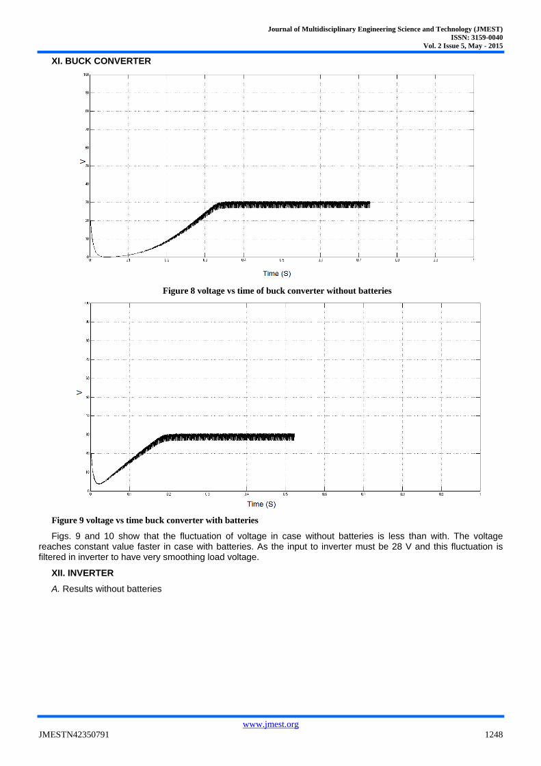
Figure 8 voltage vs time of buck converter without batteries
Figure 9 voltage vs time buck converter with batteries
Figs. 9 and 10 show that the fluctuation of voltage in case without batteries is less than with. The voltage reaches constant value faster in case with batteries. As the input to inverter must be 28 V and this fluctuation is filtered in inverter to have very smoothing load voltage.
XII. INVERTER
A. Results without batteries
Journal of Multidisciplinary Engineering Science and Technology (JMEST)
ISSN: 3159-0040
Vol. 2 Issue 5, May - 2015
www.jmest.org
JMESTN42350791 1249
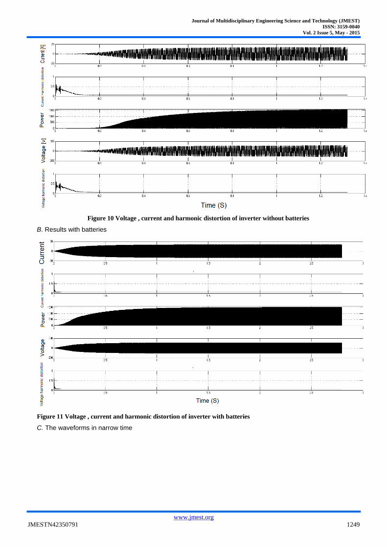
Figure 10 Voltage , current and harmonic distortion of inverter without batteries
B. Results with batteries
Figure 11 Voltage , current and harmonic distortion of inverter with batteries
C. The waveforms in narrow time
Journal of Multidisciplinary Engineering Science and Technology (JMEST)
ISSN: 3159-0040
Vol. 2 Issue 5, May - 2015
www.jmest.org
JMESTN42350791 1250
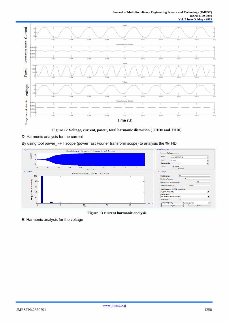
Figure 12 Voltage, current, power, total harmonic distortion ( THDv and THDi)
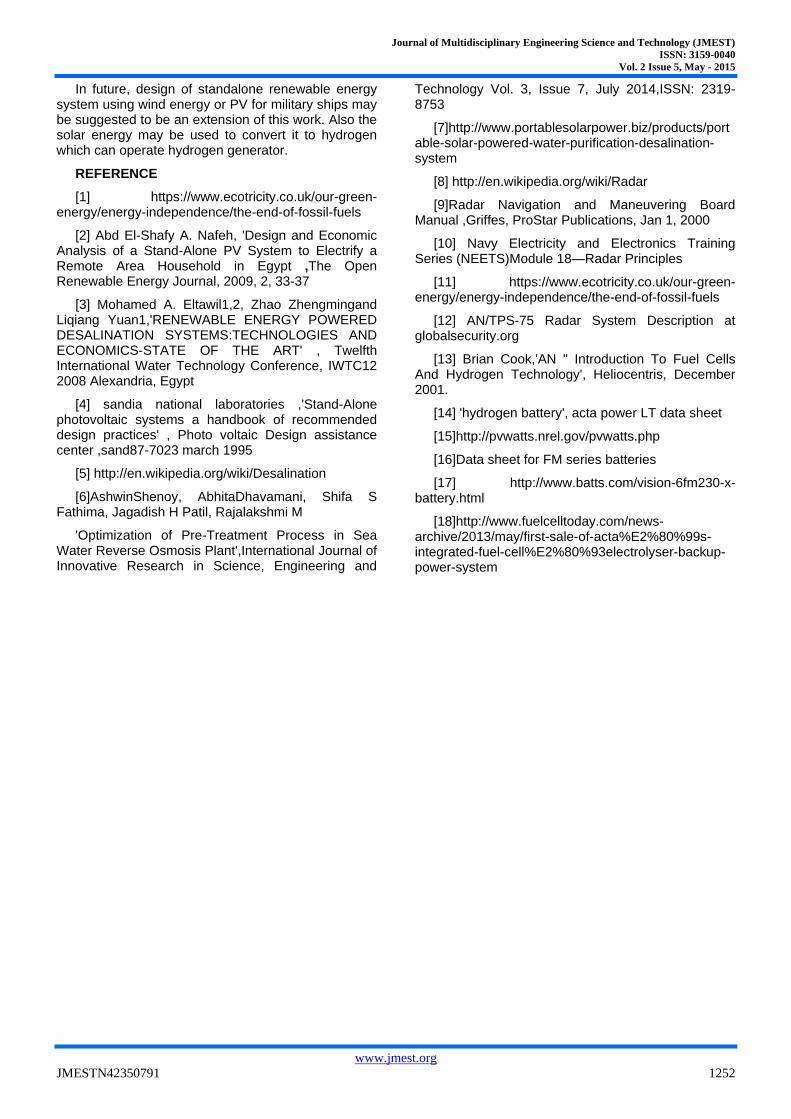
D. Harmonic analysis for the current
By using tool power_FFT scope (power fast Fourier transform scope) to analysis the %THD
Figure 13 current harmonic analysis
E. Harmonic analysis for the voltage

Journal of Multidisciplinary Engineering Science and Technology (JMEST)
ISSN: 3159-0040
Vol. 2 Issue 5, May - 2015
www.jmest.org
JMESTN42350791 1251
Figure 14 voltage harmonic analysis
Figures 10 to 14 show that:
1. Current and voltage in case of batteries reach their constant values faster than without batteries
2. Power reaches the power demanded from load in fast way in case of batteries
3. THD of voltage and current reaches its stable value in slowly in case of without batteries
4. By analysis of harmonics in case of current the %THD is 5.86 and the biggest effective harmonic order is 3
rd order (1200 HZ)with 5.5 % of fundamental
which is 14.32 A
5. By analysis of harmonic in case of voltage the % THD is 5.86 and the biggest effective
Harmonic order is 3rd
order (1200 HZ) with 5.5 % of fundamental which is 118.4
6. The waveforms of current and voltage are in phase which means that the P.F is unity which needed by load, as shown in Fig.12.
XIII. Cost Estimation [ 2,7,17,18 ]:
Table 7 Price list of the components of PV system
Item price Quantity total
PV module 270 W
1.8 $/W 40 19440 $
Battery 230 AH 339.45 $ 90 30550.5 $
Inverter 6 kw $0.831/W 1 4986 $
Battery charger 40A
5.878 $/A 2 470 $
Acta power lt 35000 euro 1 35000 euro
Portable Solar Powered Water
Purification Desalination
System
5,875 $ 1 5,875 $
The cost of the system with batteries will be = 19440+30550+4986+470+5872 = 61318 $
The cost of the system with fuel cell will be = 35000*1.18+19440+4986 + 5875=71601 $
These prices not include shipping and taxes cost.
XIV. CONCLUSION
This research work has achieved a designed stand-alone PV system to supply a combined load radar and a water desalination set which has the following characteristics:
1. The system is very stable in case of using batteries especially to overcome the high surge current Which demanded 47 A .
2. The inverter with pure sine wave output is required for radar operation.
3. Choosing DC-DC converter must be selected in which its capacitance and inductance components have no effect on the stability of the system
4. The power output of PV generator without batteries is nearly 3 KW
5. The SOC of batteries affects boosting voltage.
6. Fuel cell system can be used instead of batteries to power load during night.
Hence, the paper suggests a movable PV power supply that can be used for military purposes. The system is applicable in remote areas or desert near water sea. The system can supply energy during the day and at night. It is useful in countries where solar energy incident is very high like Egypt. The simulation using Matlab/Simulink shows that the designed PV system is stable with its components. Finally the cost of the PV system with and without fuel cell is estimated according to current prices.
Journal of Multidisciplinary Engineering Science and Technology (JMEST)
ISSN: 3159-0040
Vol. 2 Issue 5, May - 2015
www.jmest.org
JMESTN42350791 1252
In future, design of standalone renewable energy system using wind energy or PV for military ships may be suggested to be an extension of this work. Also the solar energy may be used to convert it to hydrogen which can operate hydrogen generator.
REFERENCE
[1] https://www.ecotricity.co.uk/our-green-energy/energy-independence/the-end-of-fossil-fuels
[2] Abd El-Shafy A. Nafeh, 'Design and Economic Analysis of a Stand-Alone PV System to Electrify a Remote Area Household in Egypt ,The Open Renewable Energy Journal, 2009, 2, 33-37
[3] Mohamed A. Eltawil1,2, Zhao Zhengmingand Liqiang Yuan1,'RENEWABLE ENERGY POWERED DESALINATION SYSTEMS:TECHNOLOGIES AND ECONOMICS-STATE OF THE ART' , Twelfth International Water Technology Conference, IWTC12 2008 Alexandria, Egypt
[4] sandia national laboratories ,'Stand-Alone photovoltaic systems a handbook of recommended design practices' , Photo voltaic Design assistance center ,sand87-7023 march 1995
[5] http://en.wikipedia.org/wiki/Desalination
[6]AshwinShenoy, AbhitaDhavamani, Shifa S Fathima, Jagadish H Patil, Rajalakshmi M
'Optimization of Pre-Treatment Process in Sea Water Reverse Osmosis Plant',International Journal of Innovative Research in Science, Engineering and
Technology Vol. 3, Issue 7, July 2014,ISSN: 2319-8753
[7]http://www.portablesolarpower.biz/products/portable-solar-powered-water-purification-desalination-system
[8] http://en.wikipedia.org/wiki/Radar
[9]Radar Navigation and Maneuvering Board Manual ,Griffes, ProStar Publications, Jan 1, 2000
[10] Navy Electricity and Electronics Training Series (NEETS)Module 18—Radar Principles
[11] https://www.ecotricity.co.uk/our-green-energy/energy-independence/the-end-of-fossil-fuels
[12] AN/TPS-75 Radar System Description at globalsecurity.org
[13] Brian Cook,'AN " Introduction To Fuel Cells And Hydrogen Technology', Heliocentris, December 2001.
[14] 'hydrogen battery', acta power LT data sheet
[15]http://pvwatts.nrel.gov/pvwatts.php
[16]Data sheet for FM series batteries
[17] http://www.batts.com/vision-6fm230-x-battery.html
[18]http://www.fuelcelltoday.com/news-archive/2013/may/first-sale-of-acta%E2%80%99s-integrated-fuel-cell%E2%80%93electrolyser-backup-power-system