design and control of aquarium water management … · traditional aquarium water management system...
TRANSCRIPT

International Journal of Science and Research (IJSR) ISSN (Online): 2319-7064
Impact Factor (2012): 3.358
Volume 3 Issue 9, September 2014 www.ijsr.net
Licensed Under Creative Commons Attribution CC BY
Design and Control of Aquarium Water Management System using Programmable Logic
Controller (PLC)
M.Z.A Rashid1, S.K.S Nordin2
1Faculty of Electrical Engineering, Universiti Teknikal Malaysia Melaka, Hang Tuah Jaya, 76100 Durian Tunggal, Melaka, Malaysia
2Faculty of Manufacturing Engineering, Universiti Teknikal Malaysia Melaka,
Hang Tuah Jaya, 76100 Durian Tunggal, Melaka, Malaysia
Abstract: Aquatic lives in the aquarium are easily affected with the changes of the aquarium condition such as temperature, PH level and the lighting. These conditions are very critical for the surviving of the aquatic lives in the aquarium. For the large scale aquarium, human supervisory is ineffective. Thus the implementation of Programmable Logic Controller (PLC) is applied to replace the supervisory position’s responsibility. Without the PLC and sensor, the feedback condition of the aquarium is not obtained in a fast manner. When no swift action is taken, this will increase the risk of affecting the aquatic life in the aquarium. In the end, this will lead to the death of the aquatic life. Furthermore, with the use of PLC, the aquarium condition can be monitor and being connected to other hardware application which improve the operation water system. As today the technology improved to a new level of wireless connection using Bluetooth device or wireless wavelength, enabling user to monitor and control PLC at PC distance away from PLC. Keywords: PLC, Aquarium, Water Management 1. Introduction This paper is mainly about the design and control of the aquarium management system. The design of the sytem is accomplished by using the AutoCAD software while the control of the system is done by using the OMRON CQM1H Programmable Logic Controller. The paper covers the simulation stage where after all the details of the system have been finalized, the system will be fabricated. The objectives for this project can be summarized and listed as : (i) To design an aquarium control system using PLC (water management system for aquarium), (ii) To investigate how PLC able to control the changes of the aquarium condition such as temperature, pH level, lighting, cleanliness and water level,(iii) To develop PLC programming that can automatically regulate the temperature, pH level, lighting, cleanliness and water level of the aquarium and improve the traditional aquarium water management system in terms of, performance, time and cost. 2. Motivation In the paper done by [1], the author mentioned about the effect of temperature, dissolved oxygen variation and evaporation rate in marine aquarium. [1] claimed that the marine aquarium operation will increase the water temperature, consumption of dissolved oxygen and evaporation of seawater. The rate of evaporation of water in the aquarium was estimated about 128 liters per day. On the other hand, the temperature increase in the aquarium tank was observed as 0.1 Celsius due to operation of canister filter, 0.1 Celsius due to pump and 1.1 Celsius due to aquarium lighting. Further the position of aquarium lids leads was raise in temperature of 0.5 Celsius. He concluded
that lighting deliver more heat energy to aquarium water and increase the water temperature. This may be avoided by replacing present aquarium top lid with a perforated one for release heat generated by the lighting to the atmosphere. In addition, the paper written by [2] mentioned about the development of gas-controlled aquarium (GCA). The GCA system is capable of regulating the temperature, oxygen and carbon dioxide content of water. This system is used in assays of growth and metabolic rate studies or various marine lives. GCA system used membrane contactors connected to recirculation pumps and gas sources are used to control gas concentration in the aquarium. A labview software system integrated with mass flow controllers for oxygen, carbon-dioxide and nitrogen sources allows real time, automated regulation of gas concentrations in the aquarium. Next, the paper written by [3] discussed about the actual stage of water filtration. Filtration is the advanced clearing procedure, consisting of water’s passing through a porous material that has a certain granulometry named filter layer. This is used for retention of the natural suspended particles or previous coagulated particles. Filtering is influenced by a series of parameters. The main process of water treatment can be mechanical, chemical and biological. In physical process, on the surface of the filter environment and also in its superior layer take place sedimentation and sieve process, respectively adsorption due to the electrostatic forces or ionic replacement. In the way are discharged the suspended solids, the colloidal particles, the bacteria and the remiss impurities. Second, the biological process is to removing the germs, viruses and organic matter, through slow filtration and is manifested on the surface and in the first centimeters of the filter layer. While, chemical process take place in the slow filters in the face of the oxygen remiss in water or
Paper ID: 020141316 1049
International Journal of Science and Research (IJSR) ISSN (Online): 2319-7064
Impact Factor (2012): 3.358
during the oxidation of the adsorbed organic matters, in the face of the microorganisms. Furthermore, the paper from [4] mentioned that with rising concern over the impacts of ocean acidification on marine lives, that is a need for greatly improve techniques for carrying out in situ experiments. These must be able to create a pH of 0.3 to o.5 by addition of carbon dioxide for studies of natural ecosystems such as coral reef and cold water corals. The net result of adding a small quantity of carbon dioxide to seawater is to reduce the concentration of dissolved carbonate ion and increased by carbonate ion through the reaction: CO2 + H2O + CO3
2- →2HCO3-. The
reaction proceeds more rapidly at lower pH and higher temperature. In the paper done by [5], the author had designed a portable dual purposes water filter system. The quality of water flows through the taps is still contains bacteria and minerals. The objective of this work is to provide an easy way to get safe, clean and healthy water. The portable water filter design consists of 3 parts: the filter medium, the housing and the heater. The filter medium consists of 6 layers that are top mesh-pre-filtration, activated carbon, silica, zeolites, bio boll and mineral sand. Moreover, in the paper written by [6], the author had designed and developed an automated water level sensing and controlling system using microcontroller. The design is based on monitoring and management within the context of electrical conductivity of the water. Water level management approach would help in reducing the home power consumption and as well as water overflow. The system consists of water level indicator, water level sensor, water pump controlling system and microcontroller. In the experiment, an 8 bit microcontroller, an inverter, a reserve tank, water tank and water pump have been using. Water pump has been controlled using water level sensor. Four homemade water level sensors are used to detect the water level. Inverted sensor data used to pass as the input of microcontroller. Lastly, the paper done by [7] discussed about the nitrification performance of nitrobacteria preparation for marine aquaria. Nitrification is an important process both in home aquaria and commercial aquaculture system. In the biological ammonia removal system, the nitrifying activity of bacteria has been reported to be extremely low due to the slow growth rate of nitrifying bacteria, the inhibition of nitrification by free ammonia and nitrite ions. To shorten the time needed for the establishment of the nitrification process, it is necessary to seed nitrifying bacteria inoculums to the aquatic environment. The result shows that the nitrifying bacteria exhibited obvious purification effect in marine aquarium. From the findings, the application of the consortium assures a total removal of TAN from 40mg per liter to below the detection limit within 9 days. The time required to establish nitrification was shortened by about 60% of the time required without inoculation. Based on the paper [1] and [2], the system designed in [1] had limitations especially when the operation of aquarium tank, canister filter, pump and aquarium lighting, these all operations will increase the temperatures in the aquarium
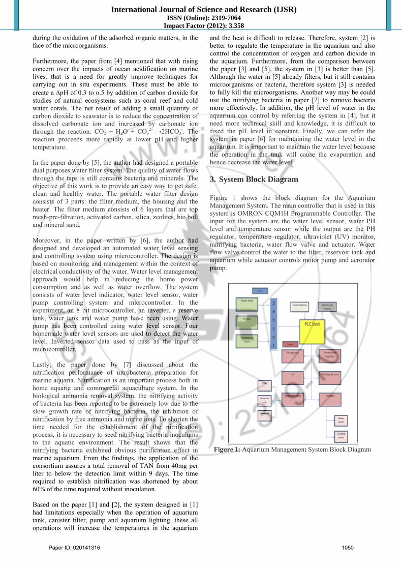
and the heat is difficult to release. Therefore, system [2] is better to regulate the temperature in the aquarium and also control the concentration of oxygen and carbon dioxide in the aquarium. Furthermore, from the comparison between the paper [3] and [5], the system in [3] is better than [5]. Although the water in [5] already filters, but it still contains microorganisms or bacteria, therefore system [3] is needed to fully kill the microorganisms. Another way may be could use the nitrifying bacteria in paper [7] to remove bacteria more effectively. In addition, the pH level of water in the aquarium can control by referring the system in [4], but it need more technical skill and knowledge, it is difficult to fixed the pH level in constant. Finally, we can refer the system in paper [6] for maintaining the water level in the aquarium. It is important to maintain the water level because the operation in the tank will cause the evaporation and hence decrease the water level. 3. System Block Diagram Figure 1 shows the block diagram for the Aquarium Management System. The main controller that is used in this system is OMRON CQM1H Programmable Controller. The input for the system are the water level sensor, water PH level and temperature sensor while the output are the PH regulator, temperature regulator, ultraviolet (UV) monitor, nutrifying bacteria, water flow valve and actuator. Water flow valve control the water to the filter, reservoir tank and aquarium while actuator controls motor pump and aerorator pump.
Figure 1: Aquarium Management System Block Diagram
Paper ID: 020141316 1050

International Journal of Science and Research (IJSR) ISSN (Online): 2319-7064
Impact Factor (2012): 3.358
Volume 3 Issue 9, September 2014 www.ijsr.net
Licensed Under Creative Commons Attribution CC BY
4. System Flowchart
5. System Design
Figure 3: Aquarium Management System Isometric View
Design
The system that is designed in this project is shown in Figure 3. It consists of reservoir, filter, aquarium, temperature regulator, drainage, CO2 tank, NF tank. The reservoir has a aerorator attached to it. Pump 1 is used to pump the water from the filter while pump 2, 3 and 4 are used to pump water to the temperature regulator and reservoir. This system is under detail study where the fabrication and other controller will be proposed later. Figure 4 shows the Aquarium Management System from the top view.
Figure 4: Aquarium Management System Top View Design 6. System Controller 6.1 Input Output Address Table
Table 1: Input Output PLC Address for the Aquarium Management System
I/O device Name Instructions 00000 Start Start button 00015 Stop Stop button 00001 S1 PH Sensor 00002 S2 Level sensor 1
Paper ID: 020141316 1051

International Journal of Science and Research (IJSR) ISSN (Online): 2319-7064
Impact Factor (2012): 3.358
00003 S3 Level sensor 2 00004 B1 Control Button 1 (for cleaning)00005 B2 Control Button 2 (for cleaning)10001 Pump 1 Pump 1 10002 Pump 2 Pump 2 10003 Aerorator motor Aerorator motor 10004 NF tank Nitrifying tank 10005 UV UV 10006 Carbon dioxide tank Carbon dioxide tank 10007 Temperature regulator Temperature regulator 10008 Pump 3 Pump 3 10009 Pump 4 Pump 4 01601 V1 Valve 1 01602 V2 Valve 2 01603 V3 Valve 3 01604 V4 Valve 4 01605 V5 Valve 5 01606 V6 Valve 6 01607 V7 Valve 7 (drainage) 01608 V8 Valve 8 01609 V9 Valve 9 01610 V10 Valve 10 (drainage) 01611 V11 Valve 11 01612 V12 Valve 12 01613 V13 Valve 13 (drainage) 01613 C1 Coil 1 01614 C2 Coil 2
TIM 000 TIM 000 Timer 000
6.2 PLC Controller Ladder Diagram
Paper ID: 020141316 1052

International Journal of Science and Research (IJSR) ISSN (Online): 2319-7064
Impact Factor (2012): 3.358
Volume 3 Issue 9, September 2014 www.ijsr.net
Licensed Under Creative Commons Attribution CC BY
7. Discussion When start button is push, coil 1(C1) will be energize. Then the contactor 1 will become normally close and allow water flow into the valve 5 from the main water inlet. When the valve 5 allows water to flow in, the pump 1 will on and start to pump water. The opening of valve 5 will allows the water pass through valves 3 and flows into the filter. So, in the filter, the water will going through filtering process. After going through filtering process, the water now will pass through valves 4. Then the valve from the reservoir tank which is valve 8 will open, and allow water to flow into the reservoir tank. When the valve 8 is opened, the aerorator motor will also on and start pumping oxygen (O2) into the tank. At the same time, the valve 8 will also activated the TIM000, and the time will start count down for every 60seconds. For every 60 seconds, the NF tank will start pumping Nitride Bacteria to the reservoir tank. In the same
time, the UV light systems will on and start to kill the germ in the water. This ensures that the water is in good condition for the aqua life. Then, the water will flow through the temperature regulator to maintain the temperature of water for aqua life. Pump 4 will on to allow the temperature regulate process. Meanwhile, pump 2 is ON all the time, to pumps water from the reservoir tank to the aquarium. The pump 2 is activated by the contactor (C1). When water pump 2 is on, the valve 12 is open and allows water to flow to the valve 1. Then, valve 1 will be open too and allow water to flow into the aquarium. There are 2 sensors in the aquarium to detect the water level in the aquarium. When the sensor sense nothing, that mean the water for the aquarium is not enough. Both pump 2 and pump 3 will on to allow pumping more water from the reservoir tank to the aquarium. When the sensor sense only
Paper ID: 020141316 1053

International Journal of Science and Research (IJSR) ISSN (Online): 2319-7064
Impact Factor (2012): 3.358
level sensor 2, the pump 2 and 3 are still on to allow more water will pump and flow to the aquarium. The pump 3 will only off when the water level reach sensor 1, which means the water in the aquarium, is enough. When 2 sensors are sense, it will allowed valve 2 to open and start repeating the process from the beginning until the stop button is pressed. 7.1 Filtering process: Filtration is the advanced clearing procedure, consisting of water’s passing through a porous material that has a certain granulometry named filter layer. This is used for retention of the natural suspended particles or previous coagulated particles. For filtering process, there are few valves that control the function of the filter. There are valve 3, 4,5,6,7 and pump 1. The coil is activated the contactor and allow valve 5 to open. Then, the pump 1 is on and starts to pump water. Valve 3 and valve 4 are control the water to flow in or out for the filter. There is a control button 1 for cleaning process too. When the button 1 is push, the valve 3 and valve 4 will close immediately. Then the valve 6 will be open and allow water to flow into the filter for cleaning. The water will drained out from valve 7 when the cleaning process is on.
Table 2: Filtering Process Condition Button
1 Valve
3 Valve
4 Valve
5 Valve
6 Valve
7 Water flowing
process OFF open open open close close
Cleaning process ON close close close open open 7.2 PH Regulating Process The PH regulating process is happened in the reservoir tank. When valve 8 is opened, the aerorator motor will also on and starts fusing oxygen (O2) into the tank. In the reservoir tank, it has a PH sensor (sensor 3) that senses the PH value of the water. When the PH value of water less than 7, the CO2 tank will on, and start pump carbon dioxide to regulate the PH value. The net result of adding a small quantity of carbon dioxide to water is to reduce the concentration of dissolved carbonate ion and increased by carbonate ion through the reaction: CO2 + H2O + CO3
2- →2HCO3-. The sensor will
check the PH value of water for every 30 seconds. When the PH above 7, the aerorator will pumps in oxygen to regulate it back to normal PH value.
Table 3: PH regulating process condition PH value Action
<7 Adding CO2
>7 Adding O2
7.3 NF (Nitrification) and UV Process The nitrification and UV process are important process to improve the quality of water in the reservoir tank. To shorten the time needed for the establishment of the nitrification process, it is necessary to seed nitrifying bacteria inoculums to the aqua environment. The aqua life is more comfortable after adding nitrifying bacteria in the water. The process will repeat for every 30 second that control by timer (TIM000). Meanwhile, the UV process can kill the unwanted germs in the water to improve water
quality. This process will also on for every 30 second in the reservoir tank.
Table 4: NF (Nitrification) and UV process condition NF process ON UV process ON
(For every 30 seconds) 7.4 Temperature Regulation Process For the temperature regulator, inside contain temperature regulation chamber to regulate the temperature to aquarium. The pump 4 is always on to ensure the temperature regulator function well with the continuous flow of water. The temperature regulator is on when the start button is push, and the coil (C1) is energize to allow contactor (C1) become normally close and allow voltage pass through.
Table 5: Temperature regulation process condition. Condition of Start button Temperature regulator
ON ON OFF OFF
7.5 Aquarium (Water Filling Process) After passing through the entire valves and some process, the water is needed to fill the aquarium. There are 2 pumps that control the flow rate of the water from the reservoir tank to the aquarium. When the sensor sense nothing, that mean the water for the aquarium is not enough. Both pump 2 and pump 3 will on to allow pumping more water from the reservoir tank to the aquarium. Both pump 2 and 3 on together can increase the water flow rate to the aquarium. When the sensor sense only level sensor 2, the pump 2 and 3 are still on to allow more water will pump and flow to the aquarium. The pump 3 will only off when the water level reach sensor 1, which means the water in the aquarium, is enough.
Table 6: The condition for the pump 2 and 3 on/off: Sensor 1 Sensor 2 Pump 2 Pump 3
0 0 ON ON 1 1 ON OFF 0 1 ON ON 1 0 - -
7.6 Drainage Process There are 3 drainage valves for the system. There are valve 7, 10 and 13. For the reservoir and the aquarium, it will automatically drain water from the valves 10 and 13 if overflow happen. While, the drainage for valve 7 are use when the cleaning process is happened. 8. Conclusion In a nutshell, this paper presents the system and controller design of the aquarium management system controlled via PLC controller. The function of PLC in our designed system is used for controlling input and output valve, operation of pump, filter cleaning and water treatment which comprise of nitrification, UV disinfection, pH leveling and as well as temperature regulation. With the use of PLC in the system, we can minimize the human errors in the water management
Paper ID: 020141316 1054

International Journal of Science and Research (IJSR) ISSN (Online): 2319-7064
Impact Factor (2012): 3.358
Volume 3 Issue 9, September 2014 www.ijsr.net
Licensed Under Creative Commons Attribution CC BY
system. PLC provides the best practical solution to the aquatic industry. 9. Acknowledgements The author wants to express appreciation to Unmanned and Autonomous Research Group (UAIR), Centre of Excellence in Robotics and Industrial Automation (CERIA) and Universiti Teknikal Malaysia Melaka (UTeM) for sponsoring this project. References [1] M. Natarajan, P. R. “Effect of Temperature, Dissolved
Oxygen Variation and Evaporation”. Current Research Journal of Biological Sciences 1(3): 72-77, 2009
[2] Barry, J. P. “A Gas-Controlled Aquarium System for Ocean Acidification Studies” OCEANS 2008 - MTS/IEEE Kobe Techno-Ocean. 2008.
[3] T. Oana, N. Valentin, L.Gabriel. “Actual Stage Of Water Filtration , Journal of Engineering Studies and Research – Volume 17,No. 4 pp 101-108, 2011.
[4] Kirkwood, W. J.,”Cabled instrument technologies for ocean acidification research” — FOCE (free ocean CO2 enrichment),2011.
[5] M. El-Harbawi. “Design Of A Portable Dual Purposes, Journal of Engineering Science and Technology, vol.5,pp 165-175, 2010.
[6] S. M. Khaled Reza, S.A,” Microcontroller Based Automated Water Level Sensing and Controlling: Design and Implementation Issue” . Proceedings of the World Congress on Engineering and Computer Science 2010 vol I, 2010.
[7] Song, Z. Nitrification “Performance of Nitrobacteria Preparation for Marine Aquaria”. 3rd International Conference on Bioinformatics and Biomedical Engineering , pp.1-4,2009.
[8] MZ Rashid, TA Izzuddin, N Abas, N Hasim, FA Azis, MSM Aras, “Control of Automatic Food Drive-Through System using Programmable Logic Controller (PLC)”. International Journal of U-& E-Service, Science & Technology,vol.6, 2013
[9] HI Jaafar, SYS Hussien, NA Selamat, MSM Aras, MZA Rashid, “Development of PID Controller for Controlling Desired Level of Coupled Tank System”, International Journal of Innovative Technology and Exploring Engineering, vol.3, 2014.
[10] N. Hasim, MZA Rashid, MSM Aras, A.M.Kassim, S.S Abdullah, “Development of fuzzy logic water bath temperature controller using MATLAB”, 2012 IEEE International Conference onControl System, Computing and Engineering (ICCSCE), IEEE, pp.11-16, 2012.
[11] AM Kassim, MS Jamri, MN Othman, MZA Rashid, SJS Ismail, “Design and Development of Low Cost Certified Green Building for Non Residential Existing Building (NREB)”, Advanced Materials Research, vol.748,2013.
Paper ID: 020141316 1055