design and control of an ultra high speed turbo compressor ... · to 30,000rpm) these...
TRANSCRIPT

Celeroton AG Technoparkstrasse 1 8005 Zurich
Switzerland
© 2012 IEEE
Transportation Electrification Conference and Expo (ITEC), 2012 IEEE
Design and Control of an Ultra High Speed Turbo Compressor for the Air Management of Fuel Cell Systems
Dongdong Zhao University of Technology of Belfort-Montbéliard, France Daniel Krähenbühl Celeroton Ltd, Switzerland Benjamin Blunier University of Technology of Belfort-Montbéliard, France Christof Zwyssig Celeroton Ltd, Switzerland Manfeng Dou Northwestern Polytechnical University, China Abdellatif Miraoui University of Technology of Belfort-Montbéliard, France
This material is posted here with permission of the IEEE. Such permission of the IEEE does not in any way imply IEEE endorsement of any of Celeroton’s products or services. Internal or personal use of this material is permitted. However, no recopying, reprinting, redistributing or reselling is permitted without the written consent from IEEE. By choosing to view this document, you agree to all provisions of the copyright laws protecting it.

Design and Control of an Ultra High Speed TurboCompressor for the Air Management of Fuel Cell
SystemsDongdong Zhao,
University of Technologyof Belfort-Montbeliard,France
Krahenbuhl Daniel,Celeroton Ltd, Switzerland
Benjamin Blunier,University of Technology
of Belfort-Montbeliard,[email protected]
Christof Zwyssig,Celeroton Ltd, Switzerland
Manfeng Dou,Northwestern Polytechnical University, China
Abdellatif MiraouiUniversity of Technology
of Belfort-Montbeliard,[email protected]
Abstract—Compressor is a crucial component of the Air Man-agement System (AMS) used in fuel cell systems. The adoption ofa turbo compressor can dramatically reduce the size of the AMS,which is a basic requirement for transportation applications. Inthis paper, the ultra high speed technology is employed in thecompressor design, which results in ultracompact size and highefficiency. One of the main disadvantages of the turbo compressorapplication is the difficulty of pressure control due to the strongcoupling between mass flow and pressure. A decoupling controlstrategy is developed so as to control the mass flow and pressureproperly. The simulation results show that the mass flow andpressure can be controlled separately using two PI controllersafter preliminary.
I. INTRODUCTION
Thanks to their low temperature working condition, the pro-ton exchange membrane fuel cells (PEMFCs) allow the systemstart up faster than those technologies using high temperaturefuel cells, which makes it most suitable for automotive applica-tions [1]. The air management system (Fig. 1) is one of the keyequipments in the operation of a fuel cell system [2], which isused to supply oxygen to the cathode. A great deal of facilitiesare needed to fulfill the task of air management, among whichthe air compressor is a crucial component. The technicalchallenges and objectives for fuel cell systems in transportationapplications are given by the Department of Energy (DOE)and are reported in [1]. Automotive fuel cell industry needs acompact, lightweight, low-cost and high efficiency compressor.This can be achieved by using turbo compressor instead ofscroll, lobe, or screw compressor, increasing the rotationalspeed [3]. A scroll compressor is employed in [1], [4], [5].In [6], a twin-screw compressor is used for the high-pressurecondition and a blower is used for the low-pressure condition.Screw or roots-type superchargers are commonly chosen fortheir easier technical implementation. The turbo compressorhas major advantages of compactness and efficiency over othercompressor types, whereas it is more critical to implement
in terms of pressure and surge control because of the strongcoupling between mass flow and pressure.
This paper focus on the design and control of an ultrahigh speed turbo compressor used in air management system.The main objective of the compressor design is to reduce thesize and weight so as to make it feasible for transportationapplication, which is achieved by increasing the rotationalspeed. The objective of the compressor control is to provideproper mass flow and pressure which fuel cell needs accordingto the load demands. In this paper, a dynamic decouplingcontroller based on neural network is proposed to deal withthe problem of strong coupling so as to control the mass flowand pressure separately.
Anode
Cathode
Compressor&motor
controller
filterair
condenser
humidifier
air
DC
DC
load
mass flowpressure
current
voltage
DC
AC
valve control
valve
sensor
Motorspeed
Fig. 1. Air management system
II. COMPRESSOR DESIGN
A. Scaling of turbo compressor and electric motor
Turbo compressors for fuel cell applications demand lowmass flow rates (10 to 30 g/s) at relatively high pressure ratios(1 to 2). For a standard speed turbo compressor (e.g. 3,000
to 30,000 rpm) these specifications result in a very low flowcoefficient:
�t1 =
Vt1
d22u2=
m
⇢t1d22u2
=m!2
⇢t14u3
2
(1)
where Vt1 is the total inlet volume flow in (m3/s), ⇢
t1 is thetotal inlet density in (kg/m3), m is the mass flow rate in (kg/s),u2 is the impeller circumferential speed at the impeller radiusd2/2 and ! the rotational speed. This low flow coefficientthen results in a very low efficiency according to [7]. Theideal flow coefficient for radial turbo compressor and withthis a higher efficiency, is reached by increasing the rotationalspeed. A further advantage of this high rotational speed is thedecrease of the impeller radius and therefore an increase inpower density in turbo machinery. Also the electrical motorpower density is roughly proportional to the speed.
P
V/ n (2)
Therefore, the overall volume and weight of a high-speedelectrically drive turbo compressor is several times lowerthan of a scroll or displacement compressors with the samespecifications for pressure ratio and mass flow which are notcapable of running at high speed [3]. A further advantage isthe low noise of a high-speed turbo compressor, comparedto standard scroll or displacement compressors, because thevibrations are both smaller and can be damped more efficientlydue to the high frequency.
B. Turbo compressor design
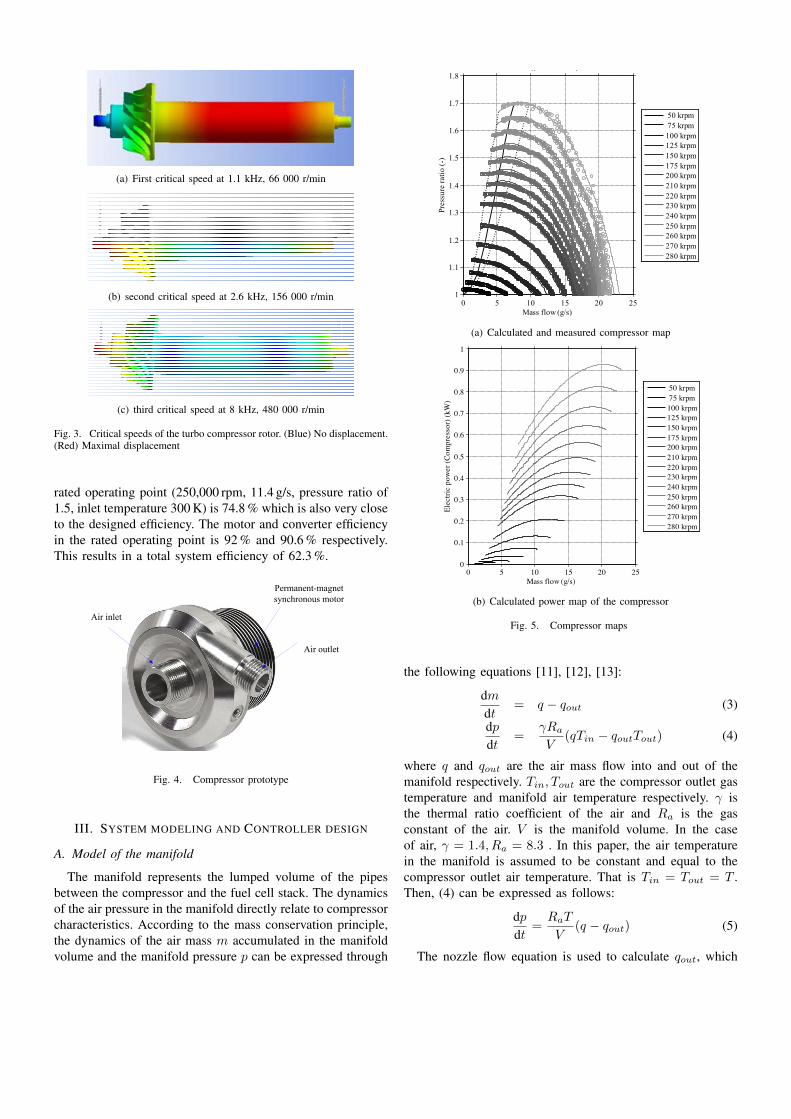
The compressor is designed for fuel cell applications, and istherefore designed for a rated mass flow of 12 g/s and a ratedpressure ratio of 1.5. The inlet conditions are ambient pressure(1 bar) and 25 �C. The turbo compressor system consists of aradial impeller with splitter blades but no shroud, a vanelessdiffuser and a spiral casing. Retaining an ideal flow coefficientof 0.085, results in a turbo compressor with an impellerdiameter of 21 mm and a rotational speed of 250,000 rpm.The assumed isentropic total-total efficiency is 74 % [7] whilethe rated compressor power is 580 W. The impeller optimiza-tion has been carried out with a 2D-throughflow code [8]and verified with 3-D computational fluid dynamics (CFD)simulations. The compressor and power map data for differentrotational speeds and variable mass flow is calculated with a1D-analytical design tool including correction factors based onempirical data from similar small high-speed compressors [9].The compressor map gets computed only from the designpoint. In Fig. 5(a) the comparison between the 1D-analyticalcompressor map and the measured compressor map is shown.
C. Electrical machine design
The electrical machine is designed for the rated specifica-tions defined by the turbo compressor design: a rotationalspeed of 250,000 r/min and a shaft power of 580 W. Theelectrical machine design comprises several challenges such asthe mechanical rotor design, particularly the stresses in the PMand the retaining titanium sleeve, additionally, high rotational
speeds usually increases the losses, mainly due to eddy currenteffects in winding, stator iron and the entire rotor (magnet,iron, sleeves), but also in higher air friction losses. Increasingthe speed with constant efficiency also results in higher lossdensity, or higher losses per surface area, therefore a thermaldesign is required. For this reason, an optimization method hasbeen developed, which takes air-friction losses, iron losses,copper losses, and eddy-current losses into account [10].The rotor losses due to armature reaction is not part ofthe optimization process, but is calculated after optimizationprocess. The stator magnetic field rotates with a high frequency(4.2 kHz); it is therefore necessary to minimize the losses inthe stator core by using amorphous iron and the eddy-currentlosses in the skewed air-gap winding by using litz wire.
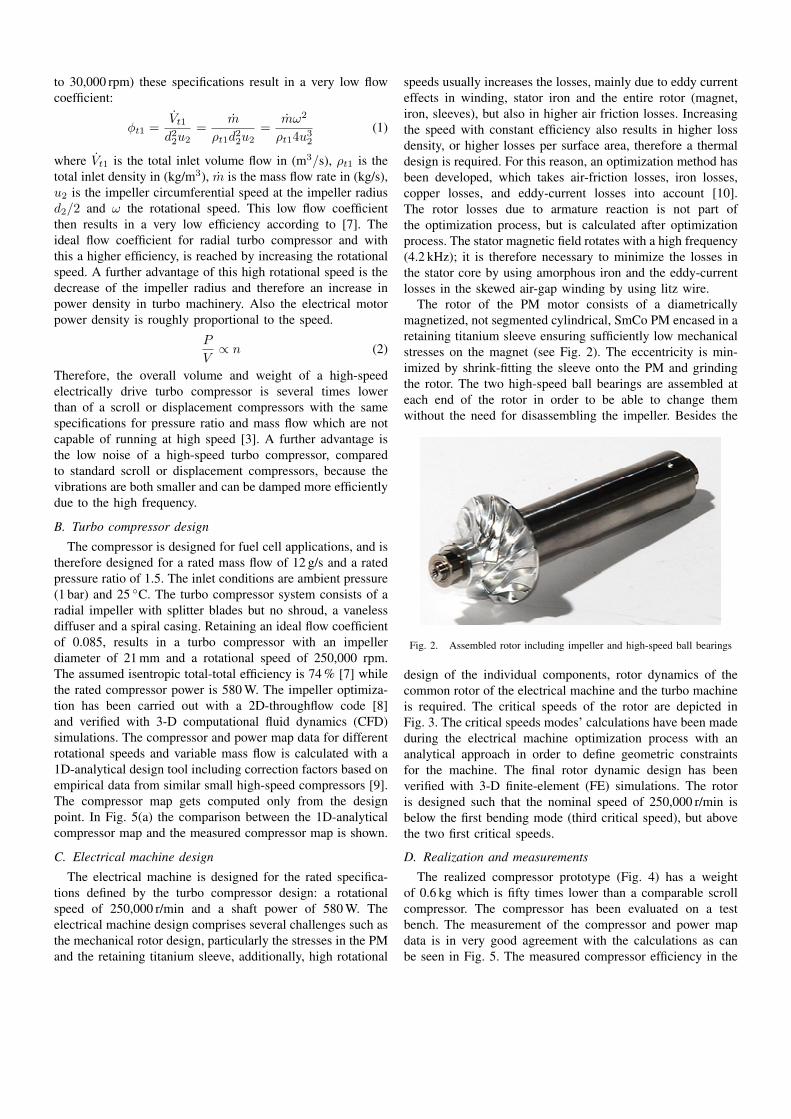
The rotor of the PM motor consists of a diametricallymagnetized, not segmented cylindrical, SmCo PM encased in aretaining titanium sleeve ensuring sufficiently low mechanicalstresses on the magnet (see Fig. 2). The eccentricity is min-imized by shrink-fitting the sleeve onto the PM and grindingthe rotor. The two high-speed ball bearings are assembled ateach end of the rotor in order to be able to change themwithout the need for disassembling the impeller. Besides the
Fig. 2. Assembled rotor including impeller and high-speed ball bearings
design of the individual components, rotor dynamics of thecommon rotor of the electrical machine and the turbo machineis required. The critical speeds of the rotor are depicted inFig. 3. The critical speeds modes’ calculations have been madeduring the electrical machine optimization process with ananalytical approach in order to define geometric constraintsfor the machine. The final rotor dynamic design has beenverified with 3-D finite-element (FE) simulations. The rotoris designed such that the nominal speed of 250,000 r/min isbelow the first bending mode (third critical speed), but abovethe two first critical speeds.
D. Realization and measurements
The realized compressor prototype (Fig. 4) has a weightof 0.6 kg which is fifty times lower than a comparable scrollcompressor. The compressor has been evaluated on a testbench. The measurement of the compressor and power mapdata is in very good agreement with the calculations as canbe seen in Fig. 5. The measured compressor efficiency in the
(a) First critical speed at 1.1 kHz, 66 000 r/min
(b) second critical speed at 2.6 kHz, 156 000 r/min
(c) third critical speed at 8 kHz, 480 000 r/min
Fig. 3. Critical speeds of the turbo compressor rotor. (Blue) No displacement.(Red) Maximal displacement
rated operating point (250,000 rpm, 11.4 g/s, pressure ratio of1.5, inlet temperature 300 K) is 74.8 % which is also very closeto the designed efficiency. The motor and converter efficiencyin the rated operating point is 92 % and 90.6 % respectively.This results in a total system efficiency of 62.3 %.
Air outlet
Air inlet
Permanent-magnet synchronous motor
Fig. 4. Compressor prototype
III. SYSTEM MODELING AND CONTROLLER DESIGN
A. Model of the manifold
The manifold represents the lumped volume of the pipesbetween the compressor and the fuel cell stack. The dynamicsof the air pressure in the manifold directly relate to compressorcharacteristics. According to the mass conservation principle,the dynamics of the air mass m accumulated in the manifoldvolume and the manifold pressure p can be expressed through
0 5 10 15 20 251
1.1
1.2
1.3
1.4
1.5
1.6
1.7
1.8Fluid: Air p
t1: 0.98 bara T
1: 25 °C
Mass flow (g/s)
Pres
sure
ratio
(-)
50 krpm 75 krpm100 krpm125 krpm150 krpm175 krpm200 krpm210 krpm220 krpm230 krpm240 krpm250 krpm260 krpm270 krpm280 krpm
(a) Calculated and measured compressor map
0 5 10 15 20 250
0.1
0.2
0.3
0.4
0.5
0.6
0.7
0.8
0.9
1Fluid: Air
Mass flow (g/s)
Elec
tric
pow
er (C
ompr
esso
r) (k
W)
50 krpm 75 krpm100 krpm125 krpm150 krpm175 krpm200 krpm210 krpm220 krpm230 krpm240 krpm250 krpm260 krpm270 krpm280 krpm
(b) Calculated power map of the compressor
Fig. 5. Compressor maps
the following equations [11], [12], [13]:
dmdt
= q � qout
(3)
dpdt
=�R
a
V(qT
in
� qout
Tout
) (4)
where q and qout
are the air mass flow into and out of themanifold respectively. T
in
, Tout
are the compressor outlet gastemperature and manifold air temperature respectively. � isthe thermal ratio coefficient of the air and R
a
is the gasconstant of the air. V is the manifold volume. In the caseof air, � = 1.4, R
a
= 8.3 . In this paper, the air temperaturein the manifold is assumed to be constant and equal to thecompressor outlet air temperature. That is T
in
= Tout
= T .Then, (4) can be expressed as follows:
dpdt
=R
a
T
V(q � q
out
) (5)
The nozzle flow equation is used to calculate qout
, which

is divided into two regions by the critical pressure ratio ⇠.
⇠ =
✓patm
p
◆
crit
=
✓2
� + 1
◆ ���1
(6)
For patm
p
> ⇠,
qout
= p·Sctrl
(✓)
vuut 2�Mair
(� � 1)RT
"✓patm
p
◆ 2�
�✓patm
p
◆ �+1�
#
(7)For patm
p
⇠,
qout
= p · Sctrl
(✓)
s2�M
air
(� � 1)RT(8)
where ✓, patm
, Mair
= 29 g/mol are the open angle ofvalve, atmosphere pressure and molar mass of air respectively.Then, the critical pressure ratio ⇠ is calculated equal to 0.528.Sctrl
(✓) is the open area of the valve:
Sctrl
(✓) = ⇡ · r · ✓ (9)
where r is the radius of the valve. In this paper, the pressurep is below 1.8. Assuming p
atm
= 1, gives patm
p
> 1/1.8 >0.528. Therefore, only (7) is used in the mathematical model.According to the analysis above, the lumped formulation ofqout
can be expressed as follows:
qout
= '(✓, p) (10)
B. System analysis
The control target is to make the mass flow q and pressureratio p track the references, which change according to theload situation. The control variables are the compressor speed!cp
and the valve open angle ✓. At an operating point, thelinearized formulation of the system can be expressed asfollows:
qp
�=
G
p11(s) Gp12(s)
Gp21(s) G
p22(s)
� !cp
✓
�(11)
Here we define
Gp
(s) =
G
p11(s) Gp12(s)
Gp21(s) G
p22(s)
�(12)
Using relative gain array RGA method in control theory [14],the interaction among multiple control loops is quantitativelyanalyzed. The RGA is a 2 ⇥ 2 matrix for a two inputs twooutputs system.
RGA =
�11 �12
�21 �22
�(13)
where
�ij
=
@yi
@uj|ur=cont
, (r 6= j)@yi
@uj|yr=cont
, (r 6= i), i = 1, 2; j = 1, 2
where y1, y2 represent the system outputs q and p respectively.u1, u2 represent the control inputs ! and ✓ respectively.However, this system is highly nonlinear which means that
the matrix Gp
(s) is not constant. Gp
(s) changes as theoperating points change. In order to analyze system nonlinearcharacteristic, the Simulink LTI toolbox is used to linearizethe system at different operating points. Part of RGA is listedin TABLE I which shows that at different operating points thedegree of coupling is different. At a specific pressure ratio,the lower mass flow the stronger coupling exist. Therefore, astatic decoupling control is not feasible.
TABLE IDYNAMIC RGA TABLE
p=1.40 p=1.30q (g/s) RGA q (g/s) RGA
15.85 0.6959 0.30410.3041 0.6959
15.89 0.7279 0.27210.2721 0.7279
14.86 0.6679 0.33210.3321 0.6679
14.96 0.7008 0.29920.2992 0.7008
13.87 0.6361 0.36390.3639 0.6361
13.89 0.6716 0.32840.3284 0.6761
12.88 0.6023 0.36390.3639 0.6023
12.08 0.6030 0.39070.3907 0.6030
9.88 0.5655 0.43450.4345 0.5655
9.98 0.5641 0.43590.4359 0.5641
C. Controller design
The control system (Fig. 6) consists of three parts: dynamicdecoupling, motor controller and valve controller. Vector con-trol is employed in the motor controller to drive the compressorand PI control is adopted for the valve position regulation.The motor controller and valve controller are well designed,so that both the compressor speed and the valve position havegood reference tracking characteristics. This paper focus on thedevelopment of the dynamic decoupling, which is employedto deal with the strong coupling problem between mass flowand pressure so as to control them separately.
DynamicDecoupling
Motor controller
Valve controller
Motor &compressor
Fuel cell
stack
ref_speed
speed
ref_angle
angle
massflow
pressure
ref_massflow
valveref_pressure
Fig. 6. Air management system controller
According to the system analysis, traditional static decou-pling is not feasible because of the coupling degree is not aconstant. On the basis of the traditional static decoupling, adynamic decoupling based on neural network is proposed (seeFig. 7). After the implementation of the decoupling matrixN(s), the compressor speed and the valve angle can beobtained as follows:
!cp
✓
�=
N11(s) N12(s)N21(s) N22(s)
� Uc1
Uc2
�(14)

TABLE IITRANSFER GAINS AT DIFFERENT OPERATING POINTS
XXXXXXXXq (g/s)p (-) 1.5 1.3 1.2
13.0 4.424e� 05 1.1773.620e� 06 �0.05970
4.978e� 05 0.68902.452e� 06 �0.03996
5.311e� 05 0.43421.768e� 06 �0.02689
12.0 4.221e� 05 1.2893.741e� 06 �0.05485
4.803e� 05 0.77202.563e� 06 �0.03887
5.160e� 05 0.49421.861e� 06 �0.02697
11.0 3.994e� 05 1.4083.862e� 06 �0.04822
4.601e� 05 0.86702.678e� 06 �0.03687
4.983e� 05 0.56531.960e� 06 �0.02663
10.0 3.741e� 05 1.5373.979e� 06 �0.03940
4.368e� 05 0.97512.797e� 06 �0.03363
4.774e� 05 0.65022.066e� 06 �0.02563
9.0 3.460e� 05 1.6704.090e� 06 �0.02796
4.102e� 05 1.0962.918e� 06 �0.02872
4.528e� 05 0.75022.177e� 06 �0.02363
8.0 3.151e� 05 1.8054.190e� 06 �0.01351
3.796e� 05 1.2303.038e� 06 �0.02160
4.239e� 05 0.86712.293e� 06 �0.02029
11N
22N12N21N
11pG
22pG12pG21pG
p
1cU
2cU T
Z)(sN )(sGp
Neural networks
qrefq
refpPI
PI
Fig. 7. Dynamic decoupling
where Uc1 and U
c2 are the outputs of the PI control as shownin Fig. 7. According to (11) and (14), the decoupling matricesare obtained:
N11(s) N12(s)N21(s) N22(s)
�=
G
p11(s) Gp12(s)
Gp21(s) G
p22(s)
��1
⇤ (15)
where⇤ =
G11(s) 0
0 G22(s)
�(16)
After decoupling, the system outputs can be expressed asfollows:
qp
�=
G11(s) 0
0 G22(s)
� Uc1
Uc2
�(17)
Then q and p can be controlled by Uc1 and U
c2 respectively.In view of the dynamic characteristic of G
p
(s), correspondingdecoupling matrices N(s) are obtained by means of a neuralnetwork which is trained off line to fulfill dynamic decoupling.The structure of the neural network, which is trained usingBack Propagation (BP) algorithm, is shown in Fig. 8. Theinputs are the operating points (q, p), and the outputs arethe decoupling matrices. In order to simplify calculations,static gains, (P1, P2, P3, P4), are used to replace the transferfunctions, (N11(s), N12(s), N21(s), N11(s)). TABLE II givespart of the static transfer gains, which are obtained by lin-earizing the system at different operating points. It should
be noticed that, this replacement may lead to the instabilityof the system. In this paper, G11(s), G11(s) are designedappropriately according to the order of G
p
(s)�1 to ensure thestability of the system.
G11(s) 0
0 G22(s)
�=
1s+1 00 1
(s+1)2
�(18)
Fig. 8. Neural network model
IV. SIMULATION RESULTS
Computer simulation is performed to verify the effectivenessand behavior of the proposed control strategy. The simulationresults are shown in Fig. 9. In order to test the influenceof sudden change of mass flow to pressure ratio, a stepchange of mass flow reference is given at 10 s. The zoom ofcorresponding deviation of pressure is shown in Fig. 10(b).In the same way, the sudden change of pressure ratio isexecuted at 14 s. The corresponding deviation of mass flowis zoomed in as shown in Fig. 10(a). The results show thatthe pressure can be maintained constant when the mass flowvaries. Furthermore, sudden change of mass flow (pressureratio) has a very weak influence on the pressure ratio (massflow).

(a) Mass flow response
(b) Pressure ratio response
Fig. 9. Simulation of mass flow and pressure tracking characteristics
13 13.2 13.4 13.6 13.8 14 14.2 14.4 14.6 14.8 1513
13.5
14
14.5
time (s)
mas
s flo
w (g
/s)
simulationreference
(a) Zoom of mass flow fluctuation in Fig.9(a)
9 9.2 9.4 9.6 9.8 10 10.2 10.4 10.6 10.8 111.28
1.29
1.3
1.31
1.32
1.33
1.34
1.35
time (s)
pres
sure
ratio
(−)
simulationreference
(b) Zoom of pressure ratio fluctuation in Fig.9(b)
Fig. 10. Zoom of deviations shown in Fig.9
V. CONCLUSION
In this paper, an ultra high speed turbo compressor isdesigned to fulfill the requirement of compactness for auto-motive applications. The challenges of ultra high speed turbocompressor design such as the mechanical rotor construction,the rotor dynamic design, the minimization of the losses inthe electric motor are highlighted and corresponding solutionshave been come up with. The size and weight meet therequirements of DOE. At the same time, the high efficiencydramatically reduces the parasitic power consumption of fuelcell systems. Both the strong coupling and highly nonlinearcharacteristics result in the difficulty of the pressure control.The coupling and nonlinear characteristics are analyzed bylinearizing the system at different operating points. On thebasis of linearization data, a dynamic decoupling controllerbased on neural network is designed. The simulation resultsshow that after decoupling the mass flow and pressure can becontrolled separately using two PI controllers.
REFERENCES
[1] B. Blunier and A. Miraoui, “Proton exchange membrane fuel cell airmanagement in automotive applications,” Journal of Fuel Cell Science
and Technology, vol. 7, no. 041007, p. 041007, 2010.[2] A. Vahidi, A. Stefanopoulou, and H. Peng, “Model predictive control for
starvation prevention in a hybrid fuel cell system,” in Proc. American
Control Conf the 2004, vol. 1, pp. 834–839.[3] D. Krahenbuhl, C. Zwyssig, H. Weser, and J. Kolar, “A miniature 500
000-r/min electrically driven turbocompressor,” Industry Applications,
IEEE Transactions on, vol. 46, no. 6, pp. 2459–2466, 2010.[4] B. Blunier, M. Pucci, G. Cirrincione, M. Cirrincione, and A. Miraoui,
“A scroll compressor with a high-performance sensorless inductionmotor drive for the air management of a pemfc system for automotiveapplications,” vol. 57, no. 6, pp. 3413–3427, 2008.
[5] B. Blunier, G. Cirrincione, Y. Herve, and A. Miraoui, “A new analyticaland dynamical model of a scroll compressor with experimental valida-tion,” International Journal of Refrigeration, vol. 32, no. 5, pp. 874–891,2009.
[6] J. Cunningham, M. Hoffman, and D. Friedman, “A comparison of high-pressure and low-pressure operation of pem fuel cell systems,” 2001.
[7] M. Casey and C. Robinson, “A guide to turbocharger compressor charac-teristics,” in Dieselmotorentechnik, 10th Symposium (Ed. M. Bargende),2006, pp. 30–31.
[8] ——, “A new streamline curvature throughflow method for radialturbomachinery,” Journal of Turbomachinery, vol. 132, p. 031021, 2010.
[9] M. V. Casey and C. J. Robinson, “A method to estimate the performancemap of a centrifugal compressor stage,” in Proc. of the ASME Turbo
Expo 2011, Vancouver, Canada.
[10] J. Luomi, C. Zwyssig, A. Looser, and J. Kolar, “Efficiency optimizationof a 100-w 500 000-r/min permanent-magnet machine including air-friction losses,” Industry Applications, IEEE Transactions on, vol. 45,no. 4, pp. 1368–1377, 2009.
[11] A. Vahidi, I. Kolmanovsky, and A. Stefanopoulou, “Constraint manage-ment in fuel cells: A fast reference governor approach,” in American
Control Conference, 2005. Proceedings of the 2005. IEEE, 2005, pp.3865–3870.
[12] J. Pukrushpan, “Modeling and control of fuel cell systems and fuelprocessors,” Amercia: The University of Michigan, 2003.
[13] M. Grujicic, K. Chittajallu, E. Law, and J. Pukrushpan, “Model-basedcontrol strategies in the dynamic interaction of air supply and fuel cell,”Proceedings of the Institution of Mechanical Engineers, Part A: Journal
of Power and Energy, vol. 218, no. 7, pp. 487–499, 2004.[14] S. Skogestad and M. Morari, “Implications of large rga-elements on
control performance,” Industrial & engineering chemistry research,vol. 26, no. 11, pp. 2323–2330, 1987.