design and control of a midair reconfigurable quadcopter
TRANSCRIPT

Design and Control of a Midair ReconfigurableQuadcopter using Unactuated Hinges
Nathan Bucki, Student Member, IEEE, Jerry Tang, Student Member, IEEE, and Mark W. Mueller, Member, IEEE
Abstract—This paper presents the design and control of a novelquadcopter capable of changing shape mid-flight, allowing foroperation in four configurations with the capability of sustainedhover in three. The normally rigid connections between thearms of the quadcopter and the central body are replaced byfree-rotating hinges that allow the arms to fold downward;no additional actuators beyond the four motors that drive thepropellers are used. Configuration transitions are accomplishedby either reducing or reversing the thrust forces producedby specific propellers during flight. Constraints placed on thecontrol inputs of the vehicle prevent the arms from foldingor unfolding unexpectedly, allowing for the use of existingquadcopter controllers and trajectory generation algorithms. Forour experimental vehicle at hover, we find that these constraintsresult in a 36% reduction of the maximum yaw torque thevehicle can produce, but do not result in a reduction of themaximum thrust or roll and pitch torques. Furthermore, theability to change configurations is shown to enable the vehicleto traverse small passages, perch on hanging wires, and performsimple grasping tasks.
Index Terms—Aerial Systems: Mechanics and Control, AerialSystems: Applications, Biologically-Inspired Robots, Reconfig-urable Aerial Systems
I. INTRODUCTION
IN recent years, quadcopters have proven to be useful inperforming a number of tasks such as building inspec-
tion, surveillance, package delivery, and search and rescue.Many extensions of the original quadcopter design have beenproposed in order to allow for new tasks to be performed,improving their utility. However, this typically requires thevehicle to carry additional hardware, which not only canreduce flight time due to the increased weight of the system,but can also increase the complexity of the vehicle, makingit more difficult to build and maintain, which can lead to ahigher likelihood of system failures. In this work we presenta design change to the quadcopter which allows the vehicleto change shape during flight, perch, and perform simpleaerial manipulation, all without requiring significant hardwareadditions (e.g. motors or complex mechanisms).
A. Related Work
Several aerial vehicles capable of changing shape have beenpreviously developed. For example, in [1] a vehicle capableof automatically unfolding after being launched from tube ispresented, and in [2] a vehicle is presented which uses foldableorigami-style arms to automatically increase its wingspan
The authors are with the High Performance Robotics Lab at the Universityof California, Berkeley, Berkeley, CA, 94709 e-mail: {nathan_bucki,jerrytang, mwm}@berkeley.edu.
during takeoff. Although such designs excel in enabling therapid deployment of aerial vehicles, they do not focus onrepeated changes of shape, and thus require intervention tobe returned to their compressed forms.
Vehicles capable of changing shape mid-flight have alsobeen developed in order to enable the traversal of narrowpassages. In [3] a vehicle that uses several servomotors toactuate a scissor-like structure that can shrink or expand thesize of the vehicle is presented, and in [4] a single servomotoris used in conjunction with an origami structure to enablethe arms of a quadcopter to shorten or lengthen during flight.Vehicles that use a central actuator to change the angle oftheir arms in an X-shape are presented in [5] and [6], and avehicle that uses four servomotors to change each arm angleis presented in [7] and extended in [8]. In [9] and [10] aquadcopter design is presented that is capable of using one ormore actuators to reposition the propellers of the vehicle tobe above one another such that the horizontal dimension ofthe vehicle is reduced. Similarly, [11] uses a single actuatorto reposition the propellers of the vehicle to be in a horizontalline, and demonstrates the vehicle being used to traverse anarrow gap.
A large body of work has also been produced regardingthe use of quadcopters to perform aerial manipulation. Aerialvehicles with the capability to interact with the environmentopen the door to a wide range of potential applications,e.g. performing construction as shown in [12]. Typicallysuch designs involve attaching one or more robot arms toa quadcopter, as shown in [13], [14], and [15] for example.Several designs involve changing the structure of the vehicle,such as [7] (described previously) and [16], which describesa ring-shaped multicopter-like vehicle capable of changingthe relative position of each propeller such that the bodyof the vehicle can be used to grasp objects. Other designs,such as [17], use passive elements to engage a gripper and asingle actuator to disengage the gripper. However, such designsrequire the vehicle to carry one or more actuators beyondthe four motors used to drive the propellers (e.g. servomotorsused for opening/closing a gripper), increasing the weight ofthe vehicle and therefore decreasing flight time. Additionalexamples of vehicles used to perform aerial manipulation canbe found in the aerial manipulation survey papers [18] and[19].
Finally, several designs have been proposed that enableaerial vehicles to perch on structures in the environment. Suchvehicles are able to fly to a desired location, attach themselvesto a feature in the environment, and then remain stationarywithout consuming significant amounts of energy (e.g. while

monitoring the surrounding area). In [20] a passive adhesivemechanism is proposed for perching on smooth surfaces,and in [21] adhesive pads are used in conjunction with aservomotor to attach and detach the vehicle from vertical walls.In [22] and [23] grippers actuated using servomotors are usedto enable perching on bars. Similarly, [24] describes a purelypassive gripper that used the weight of the vehicle to close agripper around a horizontal bar.
In this work, we extend our prior work [25] in severalways, enabling the vehicle to perform several of the previouslymentioned tasks while requiring only minor changes to thedesign and control of the vehicle compared to a conventionalquadcopter.
B. Capabilities of the novel vehicle
In [25] a quadcopter design was presented that replaced thetypically rigid connections between the arms of the quadcopterand the central body with sprung hinges that allow for thearms of the quadcopter to fold downward when low thrusts areproduced by the propellers. This feature enabled the vehicleto reduce its largest dimension while in projectile motion,allowing the vehicle to fly towards a narrow gap, collapseits arms, and then unfold after traversing the gap. In thiswork we perform two significant design changes. First, weremove the springs used to fold the arms, and instead foldeach arm by reversing the thrust direction of the attachedpropeller. Second, we change the geometry of the vehicle suchthat when two opposite arms are folded, the thrust vectors ofthe associated propellers are offset from one another, allowingfor a yaw torque to be produced when the thrust direction ofthe propellers is reversed.
No actuators or complex mechanisms are added to thevehicle, keeping its mass low, and only standard off-the-shelf components (e.g. propellers, motors, and electronic speedcontrollers) are used in the design, with the exception ofthe custom 3D printed frame of the vehicle. Thus, the maindifference between the vehicle described in this paper and aconventional quadcopter is the fact that each arm is attachedto the central body via a rotational joint rather than with arigid connection.
These changes enable the vehicle to perform a number oftasks as shown in Figure 1, namely:
• Stable flight as a conventional quadcopter with all fourarms unfolded
• Stable flight with two arms folded, allowing for thetraversal of narrow tunnels
• Grasping of and flight with objects of appropriate dimen-sions
• Perching on wires with all four arms folded• Traversal of narrow gaps in projectile motion with all
four arms foldedBy avoiding the use of complex mechanisms or additional
actuators beyond the four motors used to drive the propellers,the proposed vehicle is capable of flying in the unfoldedconfiguration with an efficiency nearly identical to that of asimilarly designed conventional quadcopter. The main draw-back of our design is the fact that stricter bounds must be
(a) (b)
(c) (d)
(e)
Fig. 1. Images of the experimental vehicle performing a variety of differenttasks. The vehicle is capable of flying like a conventional quadcopter whenin the unfolded configuration (a), but when flying in the two-arms-foldedconfiguration is able to, e.g., traverse narrow tunnels (b) and perform simpleaerial manipulation tasks such as carrying a box (c). Additionally, by allowingall four arms to fold, the vehicle is able to perch on thin wires (d), and eventraverse narrow gaps in projectile motion (e) (view from below).
placed on the four thrust forces such that the vehicle remainsin the desired configuration during flight. However, as we willshow in Section IV-C, these bounds do not significantly reducethe agility of the vehicle except in terms of a decrease of themaximum yaw torque the vehicle can produce in the unfoldedconfiguration.
II. SYSTEM MODEL
In this section we follow [25] in defining a model ofthe system and deriving the dynamics of the vehicle. Thedynamics of the vehicle are then used in Section III to derivebounds on the control inputs such that the vehicle remains inthe desired configuration.

The vehicle consists of four rigid arms connected to acentral body via unactuated rotary joints (i.e. hinges) whichare limited to a range of motion of 90◦. Unlike [25], however,each hinge is positioned such that the vehicle is only 180◦ axis-symmetric rather than 90◦ axis-symmetric. Figure 2 shows atop-down view of the vehicle, including the orientation of eachof the hinges and arms.
A. Notation
Non-bold symbols such as m represent scalars, lowercasebold symbols such as g represent first order tensors (vectors),and uppercase bold symbols such as J represent second ordertensors (matrices). Subscripts such as mB represent the bodyto which the symbol refers, and superscripts such as gE
represent the frame in which the tensor is expressed. A secondsubscript or superscript such as ωBE or RBE representswhat the quantity is defined with respect to. The symbol drepresents a displacement, ω represents an angular velocity,and R represents a rotation matrix. The skew-symmetricmatrix form of the cross product is written as S(a) such thatS(a) b = a× b.
B. Model
The system is modeled as five coupled rigid bodies: the fourarms and the central body of the vehicle. The inertial frameis notated as E, the frame fixed to the central body as B,and the frame fixed to arm i ∈ {1, 2, 3, 4} as Ai. The rotationmatrix of frame B with respect to frame E is defined as RBE
such that the quantity vB expressed in the B frame is equalto RBEvE where vE is the same quantity expressed in frameE. The orientation of arm i with respect to the central body isdefined through the single degree of freedom rotation matrixRAiB .
When used in a subscript of a displacement tensor or itstime derivatives, E is defined as a fixed point in the inertialframe, B as the center of mass of the central body, and Ai
as the center of mass of arm i. For example, dBAiBrepresents
the displacement of the center of mass of arm i with respectto the center of mass of the central body, and is expressed inthe body-fixed frame B. Furthermore, let Pi be a point alongthe thrust axis of propeller i, and let Hi be the point wherethe rotation axis of hinge i intersects with the plane swept bythe thrust axis of propeller i as arm i rotates about its hinge.
The internal reaction forces and torques acting at the hingeare defined as fri and τri respectively. The propeller attachedto arm i produces scalar thrust force fpi
and aerodynamicreaction torque τpi
in the zAidirection. We assume that the
torque produced by each propeller is piecewise linearly relatedto the propeller thrust force [26] with positive proportionalityconstants κ+and κ−such that:
τpi=
{(−1)iκ+fpi
fpi≥ 0
(−1)iκ−fpifpi
< 0(1)
where (−1)i models the handedness of the propellers, fpi < 0when the propellers are spun in reverse, and κ+ 6= κ−
when asymmetric propellers are used, as is common withquadcopters.
Fig. 2. Top-down view of vehicle in the unfolded configuration (left) andarm A1 (right). In the unfolded configuration, the thrust axis of each rotoris parallel and equidistant from its neighbor, as is typical for quadcopters.Each arm is connected to the central body by a hinge that rotates in the yAidirection, allowing the arms to independently rotate between the folded andunfolded configurations. The orientation of each hinge relative to the centralbody is determined by θ. Each propeller produces a thrust force fpi andtorque τpi at Pi in the direction of zAi
.
The mass and mass moment of inertia of the central bodytaken at the center of mass of the central body are denotedmB and JB respectively, and the mass and mass moment ofinertia arm i taken at its center of mass are denoted mAi
andJAi
respectively.
C. Dynamics
The translational and rotational dynamics of the centralbody of the vehicle and the four arms are found usingNewton’s second law and Euler’s law respectively [27]. Weassume that the only external forces and torques acting on thevehicle are those due to gravity and the thrusts and torquesproduced by each propeller (for example, aerodynamic effectsacting on the central body or arms are not considered). Thetime derivative of a vector is taken in the reference frame inwhich that vector is expressed.
We express the translational dynamics of the central body inthe inertial frame E, and the rotational dynamics of the centralbody in the body-fixed frame B. Let g be the acceleration dueto gravity. The translational dynamics of the central body arethen:
mBdEBE = mBg
E +REB4∑
i=1
fBri (2)
and the rotational dynamics of the central body are:
JBB ω
BBE + S
(ωB
BE
)JBBω
BBE
=
4∑i=1
(τBri + S
(dBHiB
)fBri
) (3)
We express the translational and rotational dynamics of armi in frame Ai. The translational dynamics of arm i are (notefAiri = RAiBfB
ri ):
mAi
(RAiEdEBE +α
)= mAi
RAiEgE +zAi
Aifpi−fAi
ri (4)

where α is
α =RAiB(S(dBBHi
)ωB
BE + S(ωB
BE
)S(dBBHi
)ωB
BE
)+ S
(dAi
HiAi
)ωAi
AiE+ S
(ωAi
AiE
)S(dAi
HiAi
)ωAi
AiE
(5)
The rotational dynamics of arm i are (note τAiri =
RAiBτBri ):
JAi
AiωAi
AiE+ S
(ωAi
AiE
)JAi
AiωAi
AiE= S
(dAi
PiAi
)zAi
Aifpi
+ zAi
Aiτpi − τAi
ri − S(dAi
HiAi
)fAiri
(6)
The equations of motion of the arm are written in terms ofωAi
AiEand ωAi
AiEfor convenience, which evaluate to:
ωAi
AiE= ωAi
AiB+RAiBωB
BE
ωAi
AiE= ωAi
AiB+RAiBωB
BE − S(ωAi
AiB
)RAiBωB
BE
(7)
Furthermore, note that the reaction torque acting in the rota-tion direction of hinge i is zero when arm i is rotating betweenthe folded and unfolded configurations (yAi
Ai· τAi
ri = 0), posi-tive when arm i is in the folded configuration (yAi
Ai·τAi
ri ≥ 0),and negative when arm i is in the unfolded configuration(yAi
Ai· τAi
ri ≤ 0). Thus, in order for arm i to remain in adesired position when starting in that position (i.e. folded orunfolded), the vehicle must be controlled such that yAi
Ai· τAi
riremains either positive (to remain folded) or negative (toremain unfolded). Such a method is presented in the followingsection.
III. CONTROL
In this section we describe the controllers used to control thevehicle in each of its configurations. We focus on three distinctconfigurations: the unfolded configuration (shown in Figure1a), the two-arms-folded configuration (shown in Figures 1band 1c), and the four-arms-folded configuration (shown inFigure 1e).
The vehicle is capable of controlled hover in both theunfolded and two-arms-folded configurations. In the unfoldedconfiguration, the vehicle acts as a conventional quadcopter;each of the four propellers produce positive thrust forces(fpi > 0) in the zB direction. However, in the two-arms-foldedconfiguration, only two propellers of the same handednessproduce positive thrust forces in the zB direction; the othertwo propellers spin in reverse, producing negative thrust forcesthat cause their associated arms to fold downward. In thisconfiguration, the folded arms are positioned such that thethrust forces produced by their associated propellers create ayaw torque that counteracts the yaw torque produced by theother two propellers. Note that for the design considered inthis paper, the arms have a 90◦ range of motion such that thethrust produced by a folded arm has no component in the zBdirection.
In the four-arms-folded configuration each of the fourpropellers are spun in reverse (fpi < 0), resulting in all fourarms folding. Although the vehicle is not capable of controlledhover in this configuration, the attitude of the vehicle can stillbe fully controlled, allowing for the vehicle to reorient itselfwhile in projectile motion.
Fig. 3. Cascaded controller used to control the vehicle.
A cascaded control structure typical of multicopter control,shown in Figure 3, is used to control the vehicle in boththe unfolded and two-arms-folded configurations. A positioncontroller first computes a desired acceleration based on posi-tion and velocity errors, allowing for the computation of thedesired total thrust in the zB direction, fΣ. Then, an attitudecontroller computes the desired torque required to align thethrust direction zB with the desired acceleration direction andachieve the desired yaw angle. Finally, the individual propellerthrust forces necessary to generate the desired total thrust anddesired body torque are computed. For each propeller, thedesired thrust is converted to a desired angular velocity, whichan electronic speed controller is used to track.
A similar control structure is used in the four-arms-foldedconfiguration. However, because the four arms do not pro-duce thrust in the zB direction while folded, we omit theposition controller and instead command desired attitudes tothe attitude controller directly. The individual thrust forcesthat minimize the sum of each thrust force squared whileproducing the desired torque are then computed. Note thesethrust forces can be efficiently computed using the Moore-Penrose pseudoinverse of the matrix relating the four thrustforces to the torque acting on the vehicle.
A. Individual thrust force computation
The individual propeller thrust forces u =(fp1 , fp2 , fp3 , fp4) are related to the desired total thrustin the zB direction fΣ and the desired torques about the axesof the body-fixed B frame, τB = (τx, τy, τz) as follows:[
fΣ
τB
]=
[MfΣ
MτB
]u =Mu (8)
where MfΣ∈ R1×4 is the mapping from u to fΣ, MτB ∈
R3×4 is the mapping from u to τB , and M ∈ R4×4 is thecombined mapping.
The mapping M is computed using the geometry of thevehicle and the torque produced by each propeller as a functionof the thrust it produces. Let dPiC
be the position of propellerPi relative to the center of mass of the entire vehicle C,and κpi
= (−1)iκ+ or κpi= (−1)iκ− depending on the
thrust direction of propeller i as defined in (1). Then, the i-thcolumns of MfΣ
and MτB are
MfΣ[i] = zBAi
· zBB , MτB [i] = S(dBPiC
)zBAi
+ κpizBAi
(9)

where we recall that zBAiis a unit vector written in the body-
fixed frame B that points in the positive thrust direction ofpropeller i.
Thus, in the unfolded configuration, Mu is the mapping ofa typical quadcopter with l defined as shown in Figure 2:
Mu =
1 1 1 1−l/2 −l/2 l/2 l/2−l/2 l/2 l/2 −l/2−κ+ κ+ −κ+ κ+
(10)
The mapping M2f for the two-arms-folded configurationwith arms A2 and A4 folded and θ defined as shown in Figure2 is defined as follows. An equivalent mapping exists for thetwo-arms-folded configuration with arms A1 and A3 folded.
M2f =
1 0 1 0−l/2 px l/2 −px−l/2 −py l/2 py−κ+ −pz −κ+ −pz
px = dBP2C,z cos(45
◦ + θ)− κ− sin(45◦ + θ)
py = dBP2C,z sin(45◦ + θ) + κ− cos(45◦ + θ)
pz =l√2
2sin θ
(11)
where we note that the arms are of equal length, i.e. dBP1C,z =
dBP2C,z = dBP3C,z = dBP4C,z .Finally, the mapping M4f for the four-arms folded config-
uration is defined as:
M4f =
0 0 0 0px px −px −pxpy −py −py pypz −pz pz −pz
(12)
The structure of these mappings can be analyzed to inferhow different parameters of the vehicle affect how the vehiclecan be controlled in each configuration. For example, we notethat when the arms are not angled (i.e. when θ = 0 as wasdone in our prior work [25]), the term pz as defined in (11)equals zero. In this case, the vehicle would only be able toproduce negative yaw torques due to the fact that the foldedarms would be unable to offset the yaw torque producedby the two unfolded arms. Similarly, if θ = 0, the vehiclewould be unable to produce any yaw torque in the four-arms-folded configuration as the bottom row of M4f would be zero.However, we observe that (10) does not depend on θ at all,showing that the thrust mapping matrix is unaffected by thechoice of arm angle in the unfolded configuration.
Note that, unlike Mu, both M2f and M4f depend on theposition of the center of mass of the vehicle in the zB directiondue to the fact that the thrust forces produced by the foldedarms are perpendicular to zB . Thus, if the position of thecenter of mass of the vehicle in the zB direction is changed(e.g. by adding a payload to the vehicle as shown in Figure1c), the mappings M2f and M4f must reflect this change.
Furthermore, because the thrust forces of the folded armsare perpendicular to zB , there can exist a nonzero force in thexB and yB directions when flying in the two- or four-armsfolded configurations. In the two-arms-folded configuration
with arms A2 and A4 folded, for example, thrusts fp2 andfp4 act in opposite directions such that they produce a forceof magnitude |fp2
− fp4|. Because this force is zero at hover
and remains small for small τx and τy (note that |fp2− fp4
|is not dependent on fΣ or τz due to the structure of M2f ), wechoose to treat such forces as disturbances in order to maintainthe simplicity of the proposed controller.
B. Attitude control
The attitude controller is designed using desired first-order behavior, described here by the rotation vector r =(φe, θe, ψe) that represents the rotation between the currentand desired attitude (i.e. a rotation about the axis defined inthe direction of r by angle ||r||). Note that, to first order,φe, θe, and ψe represent roll, pitch, and yaw respectively. Thedesired attitude is defined as that attitude at which the yawangle of the vehicle matches the desired yaw angle and atwhich the thrust direction of the vehicle matches the desiredthrust direction, which is given by the position controller (seeFigure 3).
The linearized attitude dynamics of the vehicle are then[rr
]= A
[rr
]+BτB (13)
where
A =
[0 I0 0
], B =
[0(
JCC
)−1
](14)
and where JCC is the moment of inertia of the entire vehicle
written at its center of mass. Note that JCC depends on the
configuration of the vehicle.We choose to synthesize an infinite-horizon LQR controller
[28] with state cost matrix Q ∈ R6×6 and input cost matrixRτB ∈ R3×3. For each configuration of the vehicle, we weightthe cost of each state error independently such that Q is adiagonal matrix. The values of the diagonal of Q are chosensuch that the costs associated with φe and θe (i.e. elements1 and 2) are equal and such that the costs associated withthe roll rate and pitch rate (i.e. elements 4 and 5) are equal.However, we choose to define the input cost matrix RτB usingthe mapping MτB from the individual thrust forces u to thedesired torque τB as defined in (8) (i.e. the lower three rowsof Mu, M2f , or M4f , depending on the configuration of thevehicle):
RτB = (M+τB )
TRuM+τB (15)
where M+τB is the pseudoinverse of the mapping matrix MτB ,
and Ru ∈ R4×4 is a diagonal matrix that encodes the costassociated with the thrust force produced by each propeller.
In this work we choose the diagonal entries of Ru basedupon whether the associated propeller is spinning in theforward or reverse direction, as the propeller exhibits differ-ent characteristics in each mode of operation. For example,conventional propellers produce significantly less thrust whenspinning in the reverse direction as they are typically opti-mized to spin in only the forward direction. Thus, we defineRu = diag(r+, r+, r+, r+) for the unfolded configuration,
Ru = diag(r+, r−, r+, r−) for the two-arms-folded config-uration, and Ru = diag(r−, r−, r−, r−) for the four-arms-folded configuration, where r+ is the cost associated with thepropellers spinning in the forward direction, and r− is the costassociated with the propellers spinning in the reverse direction.In general, r+ < r− as conventional quadcopter propellers areoptimized to spin in the forward direction.
By defining the input cost matrix RτB as a function of themapping matrix MτB , we can straightforwardly synthesizedifferent infinite-horizon LQR attitude controllers for eachconfiguration of the vehicle. Furthermore, the torque costmatrix RτB can be used to analyze the ability of the vehicle tocontrol its attitude in different configurations, as it describesthe cost of producing an arbitrary torque on the vehicle whileimplicitly accounting for the geometry of the vehicle due toits dependence on MτB .
C. Thrust limits
Although the thrust produced by each propeller is alreadybounded by the performance limitations of the motor driving it,we impose additional bounds which ensure the vehicle remainsin the desired configuration. Imposing these bounds ensuresthat none of the arms begin to fold or unfold unexpectedly,which means the mappings Mu, M2f , and M4f derived inSection III-A will remain valid during flight. Of course, thebounds are not imposed when changing between configura-tions.
Rather than bounding the individual thrust forces, we chooseto instead bound fΣ and τB using the model derived in SectionII. Our approach is similar to that of [25], but differs in itsinclusion of the arm angle θ, resulting in a modified expressionfor the bound.
1) Unfolded configuration bounds: We first note that byenforcing bounds that prevent each arm from folding orunfolding, the vehicle can be treated as one rigid body ratherthan five coupled rigid bodies. Thus, the acceleration of thecenter of mass of the vehicle expressed in the inertial framedECE is:
dECE = gE +1
mΣREBzBBfΣ (16)
where the total vehicle mass is mΣ = mB + 4mAi.
Similarly, the angular acceleration of the vehicle can bewritten as follows, where JB
Σ represents the moment of inertiaof the vehicle taken at its center of mass and expressed in thebody-fixed frame B. We assume that the angular velocity ofthe vehicle ωB
BE is small such that second order terms withrespect to ωB
BE can be neglected (e.g. S(ωB
BE
)JB
Σ ωBBE).
ωBBE =
(JB
Σ
)−1τB (17)
Next, after some algebraic manipulation of (4) and (6)(omitted here for brevity), we find that the reaction torqueabout hinge i, i.e. yAi
Ai· τAi
ri , is linear with respect to dECE ,ωB
BE , and propeller thrust fpi. Recall that fpi
can be computedby inverting the mapping given in (8), meaning that dECE ,ωB
BE , and fpi are all linear functions of fΣ and τB . Thus, wefind that the torque about hinge i is also a linear function offΣ and τB .
As discussed previously, arm i will remain in the unfoldedconfiguration when yAi
Ai·τAi
ri ≤ 0. Therefore, because yAi
Ai·τAi
ri
is linear with respect to fΣ and τB , the following four boundscan be computed that ensure each of the four arms remain inthe unfolded configuration:
cfifΣ + cxiτx + cyi
τy + cziτz ≥ 0, i ∈ {1, 2, 3, 4} (18)
where cfi , cxi , cyi , and czi are all constants that depend onthe physical attributes of the vehicle.
For the unfolded configuration, the constants in (18) areas follows. Here we have included the assumption that JB
Σ =diag(JB
Σ,xx, JBΣ,yy, J
BΣ,zz) in order to allow for clearer analysis
of cxi , cyi , and czi . We give the magnitudes of each term,noting that cxi , cyi , and czi have different signs dependingwhich arm they are associated with.
cfi =1
4dAi
PiHi,x− dAi
AiHi,x
mAi
mΣ(19)
|cxi| =
dAi
PiHi,x
2l−JAi
Ai,yycos(45◦ + θ) + mA sin(45◦ + θ)
JBΣ,xx
(20)
|cyi | = −dAi
PiHi,x
2l+JAi
Ai,yysin(45◦ + θ) + mA cos(45◦ + θ)
JBΣ,yy
(21)
|czi | =dAi
PiHi,x
4κ+− mA
JBΣ,zz
(22)
where mA and JAi
Ai,yyare
JAi
Ai,yy=(JAi
Ai+mAiS
(dAi
AiHi
)S(dA1
CA1
))yy
(23)
mA = mAidAi
AiHi,xdA1
CH1,y(24)
Because of the equal magnitudes of the constants cfi , cxi ,cyi
, and czi in the unfolded configuration, we can aggregatethe four bounds given in (18) into a single bound:
cfifΣ − |cxiτx| − |cyi
τy| − |cziτz| ≥ 0 (25)
Note that (25) can always be satisfied by increasing fΣ, asthis corresponds to requiring each propeller to produce morethrust (note that in general cfi > 0). By examining (19), weobserve that the bound becomes less restrictive when, e.g., theratio of the mass of an arm to the total mass of the vehicledecreases, as this results in a larger magnitude cfi . Similarly,because the magnitude of czi decreases as κ+ increases, thebound can be made less restrictive by, e.g., choosing propellerswith a larger magnitude κ+.
Finally, note that by writing this bound as a function offΣ and τB , we can apply a similar method to that presentedin [29] to reduce these control inputs in the event that thebound is not satisfied. Specifically, if the controller presentedin the previous subsections produces a fΣ and τB that does notsatisfy (25), we first reduce the magnitude of the yaw torque τzuntil the bound is satisfied or τz = 0. Next, if the bound is stillnot satisfied, we increase fΣ until the bound is satisfied or itreaches the maximum total thrust the propellers can produce. Ifthe maximum total thrust is reached, then the roll and/or pitchtorques are reduced until the bound is satisfied. In practice,
however, decreasing the roll and/or pitch torques in order toprevent the arms from folding is seldom necessary due to themagnitude of cxi and cyi relative to the other terms.
2) Two- and four-arms-folded configuration bounds: Sim-ilar expressions for cfi , cxi , cyi , and czi can be foundfor the two- and four-arms-folded configurations, which wecompute using a computer algebra system due to their al-gebraic complexity (and thus omit here for brevity).1 Notethat no aggregate bound such as (25) exists for the two-or four-arms-folded configuration, and thus it is necessaryto enforce each bound given by (18) individually. However,the hierarchical modification of the control inputs fΣ and τB
described previously can still be used to ensure the bounds aresatisfied, guaranteeing that the vehicle remains in the desiredconfiguration under the previously stated assumptions.
Numerical values for cfi , cxi, cyi
, and czi are given inSection IV-C for the experimental vehicle in both the unfoldedand two-arms-folded configurations. We do not provide suchvalues for the four-arms-folded configuration, as in practicewe have found it to be unnecessary to enforce such bounds.This is because the thrust forces required to transition into thefour-arms-folded configuration are typically large enough toprevent the arms from unfolding without the need to enforceadditional bounds.
D. Configuration transitions
Next we describe the method used to transition betweenconfigurations of the vehicle. We choose to focus on thetransitions between the unfolded and two-arms-folded con-figurations as well as between the unfolded and four-arms-folded configurations, as these are the only transitions requiredto produce the behaviors of the vehicle demonstrated inthis paper. An example of the transition from the unfoldedconfiguration to the two-arms-folded configuration and back isgiven in Section V-A, and an example of the transition from theunfolded configuration to the four-arms-folded configurationand back is given in Section V-D.
When transitioning between the unfolded and two-arms-folded configurations, we have found it sufficient to instan-taneously change between the controller used in the unfoldedconfiguration and the controller used in the two-arms-foldedconfiguration. This discrete change in controllers is largelyenabled by the fact that the vehicle possesses significantenough agility in either configuration to recover from smalldisturbances encountered during the transition. However, thetransition is complicated by the fact that the vehicle expe-riences a significant yaw disturbance during the transition.This yaw disturbance occurs because it is necessary to reversethe rotation direction of two of the propellers of the samehandedness during the transition. Specifically, the reversingpropellers cannot offset the yaw torque produced by the pro-pellers attached to the unfolded arms, which remain spinningin the forward direction. Additionally, the revering propellersexperience a change in angular momentum that results in
1We provide code for computing these bounds, as well as performing muchof the other analyses and controller syntheses described in this paper, at:https://github.com/nlbucki/MidairReconfigurableQuadcopter
a corresponding change in angular velocity of the vehicle.Thus, after completing the maneuver, the vehicle will havea significantly different yaw angle and yaw rate than whenthe maneuver was initiated. In practice, we deal with thisdifference in yaw angle by choosing the post-transition desiredyaw angle such that once the maneuver is completed the yawerror is small.
Unlike the transition to or from the two-arms-folded con-figuration, the transitions between the unfolded and four-arms-folded configurations are accomplished by commandingconstant forward or reverse thrusts while the four arms aremoving to the unfolded or folded configurations respectively.After all four arms have finished transitioning, we resumecontrolling the vehicle using either the unfolded or two-arms-folded controller as appropriate. The period of constantthrusts is required to ensure that all four arms fold or unfoldsimultaneously, and prevents any attitude errors that wouldotherwise be introduced by attempting to control the vehiclewhile the arms are transitioning (as Mu and M4f would notbe valid during the transition).
IV. EXPERIMENTAL VEHICLE DESIGN
In this section we discuss the design of the experimentalvehicle shown in Figure 1. We start by describing how the armangle was chosen based upon other properties of the vehicle,then discuss how the properties of the chosen powertrain (i.e.the battery, speed controllers, motors, and propellers) affectthe vehicle design, and finally discuss how the design of thevehicle influences several important properties of the proposedcontrollers for each configuration of the vehicle.
The properties of the experimental vehicle are given inTable I. The overall dimensions of the experimental vehiclewere chosen to be as similar as possible to a commonly usedquadcopter design. Specifically, 8 in propellers spaced 24 cmapart are used, which correspond to the same spacing and sizeof the propellers that would be used with a DJI F330 frame(e.g. as used in [30]). We chose to use commonly availablecomponents in the vehicle design to demonstrate its similarityto a conventional quadcopter, and designed the vehicle tohave a similar performance (in terms of power consumptionand agility) as a conventional quadcopter when flying in theunfolded configuration.
Onboard the vehicle, a Crazyflie 2.0 flight controller isused to run the attitude controller and to transmit individualpropeller angular velocity commands to four DYS SN30Aelectronic speed controllers (ESCs) at 500Hz. The vehicle ispowered by a three cell, 40C, 1500mAh LiPo battery, andfour EMAX MT2208 brushless motors are used to drive fourGemfan 8038 propellers.
A motion capture system is used to localize the vehicle,although in principal any sufficiently accurate localizationmethod (e.g. using onboard cameras) could be used. Notethat we do not directly measure the position of any individualarm of the vehicle, and instead only measure the position andattitude of the central body of the vehicle. The position andattitude of the vehicle are measured by the motion capturesystem at 200Hz, and the angular velocity of the vehicle is

TABLE IEXPERIMENTAL VEHICLE PARAMETERS
Symbol Parameter ValuemAi
Arm mass 67 gmB Central body mass 356 gmΣ Total vehicle mass 624 g
κ+ Propeller torque perunit positive thrust 0.0172Nm/N
κ−Propeller torque perunit negative thrust 0.038Nm/N
fmin Minimum thrust per propeller −3.4Nfmax Maximum thrust per propeller 7.8Nθ Arm angle 11.9◦
lDistance betweenadjacent propellers 24 cm
dBBH1
Position of central body centerof mass relative to hinge 1
(written in B frame)
−4.5 cm7.1 cm−0.2 cm
dAiHiAi
Position of hinge relativeto arm center of mass(written in arm frame)
−7.6 cm0 cm−1.4 cm
dAiPAi,x
Distance of propeller fromarm center of mass 1.4 cm
measured at 500Hz using an onboard rate gyroscope. Theposition controller runs on an offboard laptop and sendscommands to the vehicle via radio at 50Hz.
A. Choice of arm angle
We choose the angle that each arm makes with the diagonalof the vehicle θ, as shown in Figure 2, such that the vehicleis capable of hovering in the two-arms-folded configuration.That is, the vehicle should be capable of producing a totalthrust fΣ to offset gravity while producing zero torque on thevehicle.
Let the thrust each propeller can produce be bounded byfpi∈ [fmin, fmax], where fmin and fmax are determined by the
physical limits of the powertrain of the vehicle. Note that inour case fmin < 0 unlike conventional quadcopters which onlyallow propellers to spin in the forward direction.
We wish to find θ such that M2fu = (mΣg, 0, 0, 0) withM2f as given in (11) while satisfying constraints on the thrustseach propeller can produce. As the constraints τx = τy = 0can be trivially satisfied for any choice of θ when fp1
= fp3
and fp2= fp4
, we focus on the constraints on the total thrustfΣ and yaw torque τz:
fp1+ fp3
≥ mΣg (26)
−κ+ (fp1+ fp3
)− l√2
2sin θ (fp2
+ fp4) = 0 (27)
Thus, the following two inequalities must be satisfied inorder for the vehicle to be able to hover with two arms folded:
θ ≥ sin−1
(−κ+mΣg
l√2fmin
)fmax ≥
mΣg
2
(28)
Because the geometry of the experimental vehicle is definedsuch that an increase in θ corresponds to an increase in theminimum dimension d of the vehicle in the two-arms-foldedconfiguration as shown in Figure 4, we choose the smallest
Fig. 4. Top-down view of the vehicle in the two-arms-folded configuration.The minimum horizontal dimension of the vehicle d increases as the armangle θ increases.
θ such that the vehicle has sufficient control authority toproduce reasonable magnitude thrusts and torques with twoarms folded. Specifically, we choose
θ = sin−1
(−κ+mΣg
l√2fdes
)(29)
where fdes > fmin is the nominal thrust force produced byeach of the two folded arms during hover. We choose fdes tobe roughly half fmin (recall fmin < 0) so that the vehicle iscapable of producing roughly equal magnitude yaw torques ineach direction.
Note that the bound presented in (28) is also dependenton several other parameters of the vehicle. For example, if asmaller θ is desired, it is advantageous to minimize both themass of the vehicle mΣ and the coefficient κ+ that relates thethrust produced by each propeller to the torque acting aboutits rotation axis. Coincidentally, minimizing these quantitiesis equivalent to minimizing the power consumption of thevehicle at hover, which is typically a preeminent concern whendesigning aerial vehicles. Thus, no significant trade-off existsbetween the power consumption of the vehicle and the choiceof θ.
B. Powertrain selection
As discussed in the previous subsection, the arm angle θ isdependent on both the torque per unit positive thrust producedby each propeller κ+ as well as the maximum magnitudethrust each propeller can produce when spinning in reversefmin. Thus, in order to minimize θ, the ratio between κ+
and fmin must be minimized. To this end, the powertrain (i.e.battery, speed controllers, motors, and propellers) is chosensuch that θ is minimized while simultaneously minimizingthe power consumption of the vehicle while flying in theunfolded configuration, as this would likely be the primarymode of operation of the vehicle. In our model, fmin and fmaxare determined by the design of the powertrain, and κ+ andκ− are determined by the chosen propellers.
Although we spin several of the propellers in the reversedirection in the two- or four-arms-folded configurations, thisdoes not imply that it would necessarily be advantageousto use symmetric propellers (sometimes referred to as “3Dpropellers”) which are designed to spin in both directions.When compared to conventional propellers, symmetric pro-pellers have the advantage of being able to produce muchlarger thrusts when spinning in reverse (i.e. fmin is larger in

Fig. 5. Magnitude of thrust and torque produced by an 8038 propeller spinningin both the forward and reverse directions. A load cell capable of measuringforces and torques was used in conjunction with an optical tachometer tocollect the data. The propeller produces significantly more thrust but producesroughly the same magnitude torque when spinning in the forward directioncompared to the reverse direction for a given speed.
magnitude), but this comes at the cost of a smaller maximumforward thrust fmax and a larger torque per unit positivethrust κ+. Thus, it is possible that the use of symmetricpropellers may lead to a larger required θ if the ratio ofκ+ to fmin is larger than that of a conventional propeller.Additionally, fmax must still be large enough to satisfy theconstraint given in (28), which may be difficult to achieveusing symmetric propellers. Finally, the use of symmetricpropellers would greatly increase the power consumption ofthe vehicle when hovering in the unfolded configuration, assymmetric propellers are not optimized to minimize powerconsumption compared to conventional propellers.
To this end, we choose to use conventional quadcopterpropellers on the experimental vehicle. Figure 5 shows howthe thrust and torque produced by a Gemfan 8038 propeller arerelated to the rotational speed of the propeller, demonstratingthe difference in thrust produced by the propeller when spin-ning in the forward and reverse directions. We found that thepowertrain of the experimental vehicle was capable of drivingthe propeller to produce up to 3.4N of thrust in the reversedirection and 7.8N of thrust in the forward direction withκ+ = 0.0172Nm/N and κ− = 0.038Nm/N. This lead to achoice of θ = 11.9◦ according to (29) with fdes = 1.5N.
Finally, we note that although in theory fpican achieve
any value between fmin and fmax, in practice we restrict fpi
to not pass through zero unless the vehicle is performing aconfiguration transition that requires reversing the propeller.This is due to the fact that we use commonly availableelectronic speed controllers and brushless motors which useback-EMF to sense the speed of the motor. The use of back-EMF to sense motor speed results in significantly degradedperformance when changing directions, meaning that suchmotors are typically restricted to spin in only one direction.Although this property can affect the performance of the
proposed vehicle when changing between configurations, oncethe propellers have reversed direction they can continue tooperate without any significant change in performance. Thus,in practice we restrict the thrust forces of propellers spinningin the forward direction and reverse direction to be in [0, fmax]and [fmin, 0] respectively, and only allow the propellers tochange direction when changing between configurations.
C. Vehicle Agility
We now examine the effects of the bounds described inSection III-C on the experimental vehicle with thrust limitsfmin and fmax. For notational convenience, we define W ∈R4×4 as a matrix with each column defined by cfi , cxi
, cyi,
and czi respectively. Then, the bounds defined in (18) can berewritten as:
W
[fΣ
τB
]� 0 (30)
where � denotes an element-wise inequality, and 0 denotes avector of zeros.
Then, the matrix Wu for the experimental vehicle in theunfolded configuration is computed to be the following, wherethe first column has units of meters and the other columns areunitless.
Wu =
0.0144 −0.0421 −0.0252 −1.3040.0144 −0.0421 0.0252 1.3040.0144 0.0421 0.0252 −1.3040.0144 0.0421 −0.0252 1.304
(31)
Similarly, the matrix W2f for the experimental vehicle inthe two-arms-folded configuration is computed to be:
W2f =
0.0369 0.08 0.0225 0.00590.0237 0.345 −0.289 1.260.0369 −0.08 −0.0225 0.00590.0237 −0.345 0.289 1.26
(32)
The individual thrust limits of each propeller can be writtenin terms of fΣ and τB by utilizing the inverse of the mappingmatrix M introduced in (8):[
I−I
]M−1
[fΣ
τB
]�[1fmin−1fmax
](33)
where I the 4× 4 identity matrix, and 1 is vector of ones oflength four.
In order to compare the agility of the experimental vehicle toa conventional quadcopter, we examine how the set of feasiblevalues of fΣ and τB is reduced when imposing the boundsgiven in (30) (i.e. those that prevent the arms from foldingor unfolding). Note that both the experimental vehicle and aconventional quadcopter must satisfy the bounds on fΣ andτB given by (33) (i.e. those that ensure fpi
∈ [fmin, fmax]),but that the experimental vehicle must additionally satisfy thebounds that prevent the arms from folding or unfolding.
The reduction in agility of the experimental vehicle whenτx = τy = 0 is shown in Figure 6, where we observehow the set of feasible yaw torques τz and total thrustsfΣ is reduced in comparison to a conventional quadcopter.As shown in the figure, the bounds that prevent the armsfrom folding primarily result in a reduction in the range of

Fig. 6. Range of feasible total thrusts fΣ and yaw torques τz for theexperimental vehicle in the unfolded configuration with zero roll and pitchtorques τx = τy = 0. The dotted black line denotes the value of fΣ athover. The blue set A represents the feasible inputs when only the constraintson the minimum and maximum thrusts of each propeller fmin and fmax areconsidered. The orange set B represents the feasible inputs for a conventionalquadcopter, i.e. with fmin = 0 rather than fmin < 0. Finally, the green set Crepresents the feasible inputs when the constraints that prevent the arms fromfolding are imposed, primarily reducing the range of feasible yaw torques.Note that C ⊂ B ⊂ A.
feasible yaw torques. Specifically, the maximum yaw torquethe experimental vehicle can produce at hover (i.e. whenfΣ = mΣg and τx = τy = 0) is reduced by 36% whencompared to a conventional quadcopter. We note that thisis a significant improvement from our previous work [25],where the maximum yaw torque was reduced by roughly 75%when compared to a conventional quadcopter due to the useof springs to fold the arms rather than reverse thrust as we usein this work.
A similar analysis of the maximum magnitude roll and pitchtorques the vehicle can produce at hover shows them to beno less than those of a conventional quadcopter, indicatingthat the bounds that prevent the arms from folding given in(30) are actually less restrictive than those on each of theindividual thrust forces given in (33). Finally, we find thatthe minimum and maximum total thrust forces are also noless than those of a conventional quadcopter, which is alsoan improved result from our previous work [25] where wefound that the minimum total thrust force was 70% of thethrust force required to hover (again due to the use of springsto fold the arms). Thus, this analysis implies that the onlysignificant tradeoff between the proposed vehicle design anda conventional quadcopter (in terms of the control authorityof the vehicle) is the reduction of the maximum yaw torquethe vehicle can produce.
V. EXPERIMENTAL RESULTS
In this section, we demonstrate how the ability of theproposed vehicle to fold and unfold each arm enables itto perform a number of tasks which would be difficult orimpossible to perform using a conventional quadcopter. Wefirst show how the ability to fold two arms of the vehicleenables the vehicle to fly horizontally through narrow tunnels
Fig. 7. Composite image of the vehicle transitioning from the unfoldedto two-arms-folded configuration (left), flying through a narrow tunnel, andtransitioning back to the unfolded configuration (right).
and perform simple aerial grasping, and then demonstrate howall four arms of the vehicle can be folded to perform perchingand more aggressive vertical flight through narrow gaps.2
A. Horizontal flight through a narrow tunnel
We first demonstrate how the proposed vehicle can be usedto fly in confined spaces which would normally be inaccessibleto a conventional quadcopter of similar size. The vehicle wasflown through a tunnel with a cross section that measures43 cm by 43 cm, as shown in Figure 1b. These dimensionswere chosen such that the vehicle could not traverse thetunnel in the unfolded configuration even with perfect tra-jectory tracking, as the minimum width of the vehicle in theunfolded configuration is 43 cm. However, the minimum widthof the vehicle in the two-arms-folded configuration is 24 cm,allowing it to pass.
To perform the maneuver, the vehicle first transitions fromthe unfolded configuration to two-arms-folded configuration,then flies through the tunnel, and finally transitions back to theunfolded configuration as shown in Figure 7. The yaw angleof the vehicle was chosen to maximize the distance of thevehicle from the walls of the tunnel when flying through itscenter.
B. Grasping
Next, we show how the two-arms-folded configuration canbe used to perform a simple grasping task, as shown inFigure 8. In this experiment a box with a mass of 83 g thatmeasures 9 cm × 15 cm × 25 cm in height is used. The boxwas specifically chosen to be 9 cm in width in order to allowfor the box to be grasped without significantly changing thegeometry of the two-arms-folded configuration, as the distancebetween the legs of two opposing folded arms is approximately9 cm. Note that because the total mass of the vehicle mΣ
increases when holding the box, each of the bounds givenin (28) that govern the ability of the vehicle to hover inthe two-arms-folded configuration become more restrictive,significantly limiting the maximum mass of a box that canbe carried.
The experiment was conducted as follows: The vehiclewas first commanded to land on top of the box, which was
2Videos of each of the experiments discussed in this section can be viewedin the attached video or at https://youtu.be/xEg8GXlb82g
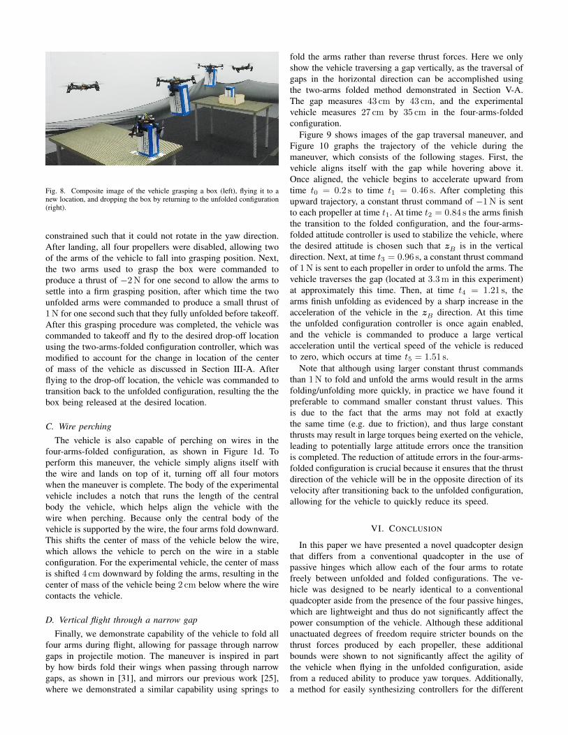
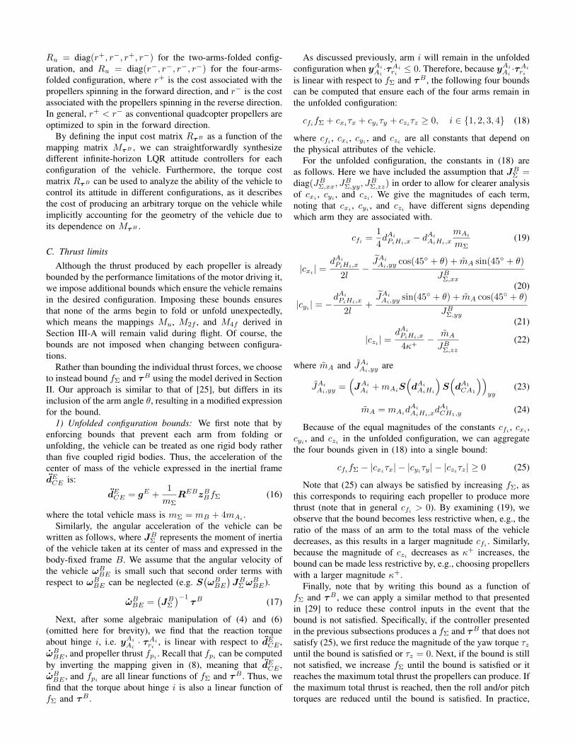
Fig. 8. Composite image of the vehicle grasping a box (left), flying it to anew location, and dropping the box by returning to the unfolded configuration(right).
constrained such that it could not rotate in the yaw direction.After landing, all four propellers were disabled, allowing twoof the arms of the vehicle to fall into grasping position. Next,the two arms used to grasp the box were commanded toproduce a thrust of −2N for one second to allow the arms tosettle into a firm grasping position, after which time the twounfolded arms were commanded to produce a small thrust of1N for one second such that they fully unfolded before takeoff.After this grasping procedure was completed, the vehicle wascommanded to takeoff and fly to the desired drop-off locationusing the two-arms-folded configuration controller, which wasmodified to account for the change in location of the centerof mass of the vehicle as discussed in Section III-A. Afterflying to the drop-off location, the vehicle was commanded totransition back to the unfolded configuration, resulting the thebox being released at the desired location.
C. Wire perching
The vehicle is also capable of perching on wires in thefour-arms-folded configuration, as shown in Figure 1d. Toperform this maneuver, the vehicle simply aligns itself withthe wire and lands on top of it, turning off all four motorswhen the maneuver is complete. The body of the experimentalvehicle includes a notch that runs the length of the centralbody the vehicle, which helps align the vehicle with thewire when perching. Because only the central body of thevehicle is supported by the wire, the four arms fold downward.This shifts the center of mass of the vehicle below the wire,which allows the vehicle to perch on the wire in a stableconfiguration. For the experimental vehicle, the center of massis shifted 4 cm downward by folding the arms, resulting in thecenter of mass of the vehicle being 2 cm below where the wirecontacts the vehicle.
D. Vertical flight through a narrow gap
Finally, we demonstrate capability of the vehicle to fold allfour arms during flight, allowing for passage through narrowgaps in projectile motion. The maneuver is inspired in partby how birds fold their wings when passing through narrowgaps, as shown in [31], and mirrors our previous work [25],where we demonstrated a similar capability using springs to
fold the arms rather than reverse thrust forces. Here we onlyshow the vehicle traversing a gap vertically, as the traversal ofgaps in the horizontal direction can be accomplished usingthe two-arms folded method demonstrated in Section V-A.The gap measures 43 cm by 43 cm, and the experimentalvehicle measures 27 cm by 35 cm in the four-arms-foldedconfiguration.
Figure 9 shows images of the gap traversal maneuver, andFigure 10 graphs the trajectory of the vehicle during themaneuver, which consists of the following stages. First, thevehicle aligns itself with the gap while hovering above it.Once aligned, the vehicle begins to accelerate upward fromtime t0 = 0.2 s to time t1 = 0.46 s. After completing thisupward trajectory, a constant thrust command of −1N is sentto each propeller at time t1. At time t2 = 0.84 s the arms finishthe transition to the folded configuration, and the four-arms-folded attitude controller is used to stabilize the vehicle, wherethe desired attitude is chosen such that zB is in the verticaldirection. Next, at time t3 = 0.96 s, a constant thrust commandof 1N is sent to each propeller in order to unfold the arms. Thevehicle traverses the gap (located at 3.3m in this experiment)at approximately this time. Then, at time t4 = 1.21 s, thearms finish unfolding as evidenced by a sharp increase in theacceleration of the vehicle in the zB direction. At this timethe unfolded configuration controller is once again enabled,and the vehicle is commanded to produce a large verticalacceleration until the vertical speed of the vehicle is reducedto zero, which occurs at time t5 = 1.51 s.
Note that although using larger constant thrust commandsthan 1N to fold and unfold the arms would result in the armsfolding/unfolding more quickly, in practice we have found itpreferable to command smaller constant thrust values. Thisis due to the fact that the arms may not fold at exactlythe same time (e.g. due to friction), and thus large constantthrusts may result in large torques being exerted on the vehicle,leading to potentially large attitude errors once the transitionis completed. The reduction of attitude errors in the four-arms-folded configuration is crucial because it ensures that the thrustdirection of the vehicle will be in the opposite direction of itsvelocity after transitioning back to the unfolded configuration,allowing for the vehicle to quickly reduce its speed.
VI. CONCLUSION
In this paper we have presented a novel quadcopter designthat differs from a conventional quadcopter in the use ofpassive hinges which allow each of the four arms to rotatefreely between unfolded and folded configurations. The ve-hicle was designed to be nearly identical to a conventionalquadcopter aside from the presence of the four passive hinges,which are lightweight and thus do not significantly affect thepower consumption of the vehicle. Although these additionalunactuated degrees of freedom require stricter bounds on thethrust forces produced by each propeller, these additionalbounds were shown to not significantly affect the agility ofthe vehicle when flying in the unfolded configuration, asidefrom a reduced ability to produce yaw torques. Additionally,a method for easily synthesizing controllers for the different

Fig. 9. Image sequence of the vehicle transitioning from the unfolded to the four-arms-folded configuration and back in order to traverse a narrow gap. Dataassociated with this experiment is shown in Figure 10.
Fig. 10. Trajectory of the vehicle while passing downward through a narrowgap in the four-arms-folded configuration. The position and velocity of thevehicle are given in the vertical zE direction as measured by the motioncapture system, and the proper acceleration is given in the zB directionas measured by the onboard accelerometer. The vehicle starts acceleratingupward at time t0, and commands each propeller to produce a constantnegative thrust at time t1, initiating the transition to the four-arms-foldedconfiguration. At time t2 the arms finish folding, and the four-arms-foldedcontroller is used to stabilize the attitude of the vehicle. Next, at time t3,a constant positive thrust command is sent to each motor to initiate thetransition back to the unfolded configuration, resulting in the vehicle returningto the unfolded configuration at time t4. Finally, the vehicle is commandedto accelerate upward to reduce its downward velocity until the vehicle comesto rest at time t5.
configurations of the vehicle was presented and used to controlthe attitude of the vehicle in both the two- and four-arms-folded configurations.
The design of the vehicle was also analyzed based uponthe ability of the vehicle to hover in the two-arms-foldedconfiguration. Specifically, it was shown that the angle ofthe arms relative to the central body is bounded from belowby a function of the characteristics of the propellers and themass and size of the vehicle. This lower bound, however,is structured such that it becomes less strict as the powerconsumption of the vehicle in the unfolded configurationis reduced, meaning that no tradeoff exists between vehiclepower consumption and arm angle. A simple characterizationof a conventional quadcopter propeller was also performed,showing that although significantly less thrust is producedby the propeller when spinning in reverse, such propellerscan produce enough reverse thrust to enable the vehicle tobe controlled in the two-arms-folded configuration with areasonably small arm angle.
Finally, the viability of the design was demonstrated byconstructing an experimental vehicle using commonly avail-able quadcopter components (e.g. standard propellers, motors,etc.), which was shown to be capable of performing a numberof tasks that a conventional quadcopter could not perform.
ACKNOWLEDGEMENT
This material is based upon work supported by the Na-tional Science Foundation Graduate Research Fellowship un-der Grant No. DGE 1752814 and by the Berkeley Fellowshipfor Graduate Study. The experimental testbed at the HiPeRLabis the result of contributions of many people, a full list ofwhich can be found at hiperlab.berkeley.edu/members/.
REFERENCES
[1] A. Bouman, P. Nadan, M. Anderson, D. Pastor, J. Izraelevitz, J. Bur-dick, and B. Kennedy, “Design and autonomous stabilization of aballistically-launched multirotor,” in 2020 IEEE International Confer-ence on Robotics and Automation (ICRA). IEEE, 2020, pp. 8511–8517.
[2] S. Mintchev, L. Daler, G. L’Eplattenier, L. Saint-Raymond, and D. Flo-reano, “Foldable and self-deployable pocket sized quadrotor,” in 2015IEEE International Conference on Robotics and Automation (ICRA).IEEE, 2015, pp. 2190–2195.
[3] N. Zhao, Y. Luo, H. Deng, and Y. Shen, “The deformable quad-rotor: Design, kinematics and dynamics characterization, and flightperformance validation,” in 2017 IEEE/RSJ International Conference onIntelligent Robots and Systems (IROS). IEEE, 2017, pp. 2391–2396.

[4] D. Yang, S. Mishra, D. M. Aukes, and W. Zhang, “Design, planning,and control of an origami-inspired foldable quadrotor,” in 2019 AmericanControl Conference (ACC). IEEE, 2019, pp. 2551–2556.
[5] A. Desbiez, F. Expert, M. Boyron, J. Diperi, S. Viollet, and F. Ruffier,“X-morf: A crash-separable quadrotor that morfs its x-geometry inflight,” in 2017 Workshop on Research, Education and Developmentof Unmanned Aerial Systems (RED-UAS). IEEE, 2017, pp. 222–227.
[6] Y. Bai and S. Gururajan, “Evaluation of a baseline controller forautonomous figure-8 flights of a morphing geometry quadcopter: Flightperformance,” Drones, vol. 3, no. 3, p. 70, 2019.
[7] D. Falanga, K. Kleber, S. Mintchev, D. Floreano, and D. Scaramuzza,“The foldable drone: A morphing quadrotor that can squeeze and fly,”IEEE Robotics and Automation Letters, vol. 4, no. 2, pp. 209–216, 2018.
[8] A. Fabris, K. Kleber, D. Falanga, and D. Scaramuzza, “Geometry-aware compensation scheme for morphing drones,” arXiv preprintarXiv:2003.03929, 2020.
[9] G. O. Vargas, C. Hintz, L. R. G. Carrillo, F. M. Palacios, and E. S. E.Quesada, “Dynamic modeling of a multi-rotorcraft uas with morphingcapabilities,” in 2015 International Conference on Unmanned AircraftSystems (ICUAS). IEEE, 2015, pp. 963–971.
[10] A. Sakaguchi, T. Takimoto, and T. Ushio, “A novel quadcopter witha tilting frame using parallel link mechanism,” in 2019 InternationalConference on Unmanned Aircraft Systems (ICUAS). IEEE, 2019, pp.674–683.
[11] V. Riviere, A. Manecy, and S. Viollet, “Agile robotic fliers: A morphing-based approach,” soft robotics, vol. 5, no. 5, pp. 541–553, 2018.
[12] Q. Lindsey, D. Mellinger, and V. Kumar, “Construction with quadrotorteams,” Autonomous Robots, vol. 33, no. 3, pp. 323–336, 2012.
[13] J. Thomas, J. Polin, K. Sreenath, and V. Kumar, “Avian-inspired grasp-ing for quadrotor micro uavs,” in ASME 2013 international designengineering technical conferences and computers and information inengineering conference. American Society of Mechanical EngineersDigital Collection, 2013.
[14] M. Orsag, C. Korpela, M. Pekala, and P. Oh, “Stability control in aerialmanipulation,” in 2013 American Control Conference. IEEE, 2013, pp.5581–5586.
[15] C. Korpela, M. Orsag, and P. Oh, “Towards valve turning using a dual-arm aerial manipulator,” in 2014 IEEE/RSJ International Conference onIntelligent Robots and Systems. IEEE, 2014, pp. 3411–3416.
[16] T. Anzai, M. Zhao, S. Nozawa, F. Shi, K. Okada, and M. Inaba, “Aerialgrasping based on shape adaptive transformation by halo: horizontalplane transformable aerial robot with closed-loop multilinks structure,”in 2018 IEEE International Conference on Robotics and Automation(ICRA). IEEE, 2018, pp. 6990–6996.
[17] D. Mellinger, Q. Lindsey, M. Shomin, and V. Kumar, “Design, modeling,estimation and control for aerial grasping and manipulation,” in 2011IEEE/RSJ International Conference on Intelligent Robots and Systems.IEEE, 2011, pp. 2668–2673.
[18] X. Meng, Y. He, and J. Han, “Survey on aerial manipulator: System,modeling, and control,” Robotica, pp. 1–30.
[19] H. B. Khamseh, F. Janabi-Sharifi, and A. Abdessameud, “Aerial manip-ulationa literature survey,” Robotics and Autonomous Systems, vol. 107,pp. 221–235, 2018.
[20] E. W. Hawkes, D. L. Christensen, E. V. Eason, M. A. Estrada, M. Hev-erly, E. Hilgemann, H. Jiang, M. T. Pope, A. Parness, and M. R.Cutkosky, “Dynamic surface grasping with directional adhesion,” in2013 IEEE/RSJ International Conference on Intelligent Robots andSystems. IEEE, 2013, pp. 5487–5493.
[21] A. Kalantari, K. Mahajan, D. Ruffatto, and M. Spenko, “Autonomousperching and take-off on vertical walls for a quadrotor micro air vehicle,”in 2015 IEEE International Conference on Robotics and Automation(ICRA). IEEE, 2015, pp. 4669–4674.
[22] K. M. Popek, M. S. Johannes, K. C. Wolfe, R. A. Hegeman, J. M. Hatch,J. L. Moore, K. D. Katyal, B. Y. Yeh, and R. J. Bamberger, “Autonomousgrasping robotic aerial system for perching (agrasp),” in 2018 IEEE/RSJInternational Conference on Intelligent Robots and Systems (IROS).IEEE, 2018, pp. 1–9.
[23] K. Hang, X. Lyu, H. Song, J. A. Stork, A. M. Dollar, D. Kragic,and F. Zhang, “Perching and restinga paradigm for uav maneuveringwith modularized landing gears,” Science Robotics, vol. 4, no. 28, p.eaau6637, 2019.
[24] C. E. Doyle, J. J. Bird, T. A. Isom, J. C. Kallman, D. F. Bareiss, D. J.Dunlop, R. J. King, J. J. Abbott, and M. A. Minor, “An avian-inspiredpassive mechanism for quadrotor perching,” IEEE/ASME TransactionsOn Mechatronics, vol. 18, no. 2, pp. 506–517, 2012.
[25] N. Bucki and M. W. Mueller, “Design and control of a passivelymorphing quadcopter,” in IEEE International Conference on Roboticsand Automation (ICRA). IEEE, 2019, pp. 9116–9122.
[26] P. Pounds, R. Mahony, P. Hynes, and J. M. Roberts, “Design of a four-rotor aerial robot,” in Proceedings of the 2002 Australasian Conferenceon Robotics and Automation (ACRA 2002). Australian Robotics &Automation Association, 2002, pp. 145–150.
[27] P. H. Zipfel, Modeling and Simulation of Aerospace Vehicle Dynamics,2nd ed. American Institute of Aeronautics and Astronautics, 2007.
[28] B. Anderson and J. Moore, Optimal Control: Linear Quadratic Methods.Prentice-Hall International, 1989.
[29] M. Faessler, D. Falanga, and D. Scaramuzza, “Thrust mixing, saturation,and body-rate control for accurate aggressive quadrotor flight,” IEEERobotics and Automation Letters, vol. 2, no. 2, pp. 476–482, 2017.
[30] N. Bucki and M. W. Mueller, “A novel multicopter with improved torquedisturbance rejection through added angular momentum,” InternationalJournal of Intelligent Robotics and Applications, vol. 3, no. 2, pp. 131–143, 2019.
[31] I. Schiffner, H. D. Vo, P. S. Bhagavatula, and M. V. Srinivasan, “Mindingthe gap: in-flight body awareness in birds,” Frontiers in zoology, vol. 11,no. 1, p. 64, 2014.