design and construction of motor mounts - robotics...
TRANSCRIPT

Design and Construction of Motor Mounts
For
Renewable Energy Vehicle
Dyi Zen Tan (10545137)
Supervisor: Dr Kamy Cheng
3rd
November 2008
Synopsis
Final Year Thesis Dyi Zen Tan i
Synopsis
In Australia, the large consumption of internal combustion engine (ICE) vehicle
had produced large amount of pollutants and greenhouse gasses. In order to reduce the
demands on using ICE vehicle, the UWA Renewable Energy Vehicle team has planned
to demonstrate the viability of using renewable energy sources for transport by building
an electric commercial car from an ICE car. The complete converted car is aimed to
register as license road vehicle. This thesis describes the evaluations of parts
retainability, the methodology used in the design and construction of motor mounts, as
well as performance evaluation of finished product.
The early stage of motor installation requires an investigation and evaluation on
the parts in the engine compartment in order to identify particular parts retainability. All
of the evaluations were based on passenger’s comfort, safety and vehicle performance
to determine the retainability of particular parts.
In this project, a motor mounts was designed to mount the motor in the engine
compartment. All the motor mount designs must conduct with the Australia Design
Rules 2008 and National Code of Practice for light vehicle construction and
modification. Besides, analysis such as fabrication cost and complexity, material cost,
fabrication time was considered in this project. Once complete, performance evaluation
was conducted to the finished product.
The complete electric car is aimed to launch at the end of 2008. Although the motor
mounts had been constructed and had achieved a huge success, there is much room for
improvement of the motor mounts design for the performance electric car project.

+ Letter of Transmittal
______________________________________________________________________
Final Year Thesis Dyi Zen Tan ii
Letter of Transmittal
Dyi Zen Tan
2/26 James Street,
Cannington 6017 WA,
Australia.
Associate Professor Carolyn Oldham,
The Dean
Faculty of Engineering, Computing and Mathematics,
The University of Western Australia,
Crawley, 6009 WA.
Dear Associate Professor Oldham,
It is with great pleasure that I submit this thesis named ‘Design and Construction of
Motor Mounts for Renewable Energy Vehicle’, to the Faculty of Engineering, Computing
and Mathematics, UWA, as part of the requirement for the degree of my Bachelor of
Engineering (Mechanical)
Your Sincerely,
Dyi Zen Tan,
10545137
+ Acknowledgements
______________________________________________________________________
Final Year Thesis Dyi Zen Tan iii
Acknowledgements
I would like to appreciate to the following people for the contributions, supports
and guidance throughout my final year project.
Firstly, I would like to thank Associate Professor Thomas Bräunl, for his guidance,
patience and support throughout my final year of university.
Secondly, I would like to thank to Dr Kamy Cheng, my supervisor, mostly for his
assistance and guidance. Without you, I could not have complete or structure my final
year thesis.
Special thanks to all the electrical workshop staffs, especially Fogden Ken for all
the technical support and help in manufacturing the motor mounts.
Many thanks to the physic laboratory and workshop staffs for helping me in the
manufacture process of the motor mounts.
Thanks to Ivan Neubronner, for all of his patience, support and dedication of time
towards the supervision of this project.
Rohan Mathew, my project group leader in REV team, for his support and
assistance in various design issue.
Steve Ip and Winston Ma, my project mates of REV mechanical team, and all the
UWA REV Team members for the opportunity to take part in this interesting project.
To my friends and family, thanks for their support throughout the year.
And last but not least, all the engineering students, thanks for accompany me for
many long nights in computer lab and making such an enjoyable life in my final year.

+ Contents
______________________________________________________________________
Final Year Thesis Dyi Zen Tan iv
Table of Contents
1. Introduction ............................................................................................................. 1
1.1 The Renewable Energy Vehicle ........................................................................ 1
1.2 Final Year Project Scope ................................................................................... 2
2. Literature Survey .................................................................................................... 3
2.1 Chapter Overview ............................................................................................. 3
2.2 Renewable Energy Vehicle Overview ............................................................... 3
2.2.1 Fuel Cell Vehicle ........................................................................................... 3
2.2.2 Solar Vehicle ................................................................................................. 3
2.2.3 Battery Electric Vehicle ................................................................................. 3
2.2.4 Plug-in Hybrid Vehicle .................................................................................. 4
2.3 Motor Mounting Kits ........................................................................................ 4
2.3.1 Rear Support Motor Mounts. ........................................................................ 5
2.3.2 Front Motor Support Mounts ........................................................................ 5
2.3.3 Coupling ........................................................................................................ 6
2.3.3.1 Set Screw Coupling ............................................................................... 6
2.3.3.2 Shrink Fit Coupling ............................................................................... 7
2.3.3.3 Tapper Lock Hub ................................................................................... 7
2.4 Existing University REV Project ...................................................................... 8
2.4.1 Two-seater Renewable Energy Vehicle by The University of South
Australia .................................................................................................................... 8
2.4.2 Indian First Plug-in Hybrid Car - Chimera Project ....................................... 8
2.4.3 Centaurus-The University of Minnesota Solar Vehicle Project (UMNSVP) 9
2.4.4 Electric Blue by Brigham Young University ................................................ 9
3. Retainability of Original Parts and Components for Hyundai Getz ................ 10
3.1 Chapter Overview ........................................................................................... 10
3.2 Methodology ................................................................................................... 10
3.2.1 Category A .................................................................................................. 10
3.2.2 Category B .................................................................................................. 11
3.2.3 Category C .................................................................................................. 11
3.3 Result and Discussion ..................................................................................... 12
+ Contents
______________________________________________________________________
Final Year Thesis Dyi Zen Tan v
3.3.1 Category A .................................................................................................. 12
3.3.2 Category B .................................................................................................. 12
3.3.2.1 Clutch System ..................................................................................... 12
3.3.2.2 Air Conditioner System ...................................................................... 14
3.3.2.3 12 Volt Battery .................................................................................... 16
3.3.2.4 Power Steering Systems ...................................................................... 16
3.3.3 Category C .................................................................................................. 16
3.3.3.1 Transmission ....................................................................................... 16
3.3.3.2 Engine Mount Rubber ......................................................................... 17
4. Design of Motor Mounts for an Electric Motor ................................................. 18
4.1 Chapter Overview ........................................................................................... 18
4.2 Aims of the REV Project ................................................................................. 18
4.3 Constraints ...................................................................................................... 18
4.3.1 The Main Functions of Engine Mounts ...................................................... 19
4.3.2 Requirements of Qualified Motor Mounts Based on the Original Engine
Mounts .................................................................................................................... 19
4.4 Design and construction of Motor Mounts ..................................................... 21
4.4.1 Design and Construction of Frontal Support .............................................. 21
4.4.1.1 Methodology of Front Support Design ............................................... 21
4.4.1.1.1 Critical Distance ............................................................................ 22
4.4.1.1.2 Determination of the Shape of Adapter Plate and the Transmission
Bolts Hole Location ........................................................................................ 23
4.4.1.1.3 Determination of the Adapter Plate Centre Point .......................... 25
4.4.1.1.4 Conceptual Design of Adapter Plate ............................................. 26
4.4.1.1.5 Modelling of Adapter Plate ........................................................... 26
4.4.1.1.6 Material Selection and Fabrication of Adapter Plate ..................... 27
4.4.1.2 Result and Discussion for Adapter Plate ............................................. 27
4.4.1.2.1 Initial Design of Adapter Plate ...................................................... 27
4.4.1.2.2 Final Design of Adapter Plate ....................................................... 28
4.4.1.2.3 Material Selection and Fabrication of Adapter Plate ..................... 30
4.4.2 Design and Construction of Rear Support .................................................. 31
4.4.2.1 Methodology of Rear Support Design ................................................ 31
4.4.2.1.1 Measurement of Vertical Distance and Horizontal Distance ......... 32
4.4.2.1.2 Conceptual Design, Modelling and Fabrication of Motor Rear
Support 33
+ Contents
______________________________________________________________________
Final Year Thesis Dyi Zen Tan vi
4.4.2.2 Result and Discussion for Motor Rear Support .................................. 34
4.4.2.2.1 Initial Design ................................................................................. 34
4.4.2.2.2 Improved Design of Rear Support Mount ..................................... 35
4.4.2.2.3 Final Design of the Rear Support Mount ...................................... 35
4.4.2.2.4 Material Selection and Fabrication for Rear Support Mount ........ 36
4.4.3 Design and Construction of Mounting Bar ................................................. 37
4.4.3.1 Methodology of Mounting Bar Design ............................................... 37
4.4.3.1.1 Conceptual Design and Modelling of Mounting Bar Design ........ 38
4.4.3.1.2 Material Selection and Fabrication of Mounting Bar .................... 38
4.4.3.2 Result and Discussion of Mounting Bar Design ................................. 38
4.4.3.2.1 Final Design .................................................................................. 38
4.4.4 Design and Construction of Coupling ......................................................... 39
4.4.4.1 Methodology of Coupling Design ....................................................... 39
4.4.4.1.1 Motor Shaft Structure .................................................................... 40
4.4.4.1.2 Transmission Shaft Structure......................................................... 40
4.4.4.1.3 Conceptual Design, Modelling and Fabrication of Coupling ........ 41
4.4.4.2 Result and Discussion of Coupling Design ......................................... 41
4.4.4.2.1 Initial Design for Motor Coupling ................................................. 41
4.4.4.2.2 Final Design of Motor Coupling ................................................... 42
4.4.4.2.3 Final Design of Transmission Coupling ........................................ 43
4.4.4.2.4 Connection of Motor Coupling and Transmission Coupling ........ 43
4.5 Assembly of Motor Mounts ............................................................................ 46
5. Performance Evaluation ....................................................................................... 47
6. Conclusion .............................................................................................................. 48
7. Recommendations of Future Project ................................................................... 48
8. References .............................................................................................................. 49
9. Appendix ................................................................................................................ 52
9.1 Appendix A: Dimension of Advanced DC #FB1-4001, 9.1", single shaft...... 52
9.2 Appendix B : Torque Curve of Advanced DC #FB1-4001, 9.1", single shaft 53
9.3 Appendix C: Dimension of Transmission Coupling ....................................... 54
9.4 Appendix D: Dimension of Motor Coupling .................................................. 55
9.5 Appendix E: Material Properties of Aluminium Alloy 5083 Series ............... 56

+ Contents
______________________________________________________________________
Final Year Thesis Dyi Zen Tan vii
List of Tables
Table 3.1 ......................................................................................................................... 11
Table 3.2 ......................................................................................................................... 11
Table 3.3 ......................................................................................................................... 12
Table 3.4 ......................................................................................................................... 13
Table 3.5 ......................................................................................................................... 13
Table 3.6 ......................................................................................................................... 15
Table 3.7: ........................................................................................................................ 15
Table 4.1 ......................................................................................................................... 28
Table 4.2 ......................................................................................................................... 28
Table 4.3 ......................................................................................................................... 33
Table 4.4 ......................................................................................................................... 35
Table 4.5 ......................................................................................................................... 37
Table 4.6 ......................................................................................................................... 38
+ Contents
______________________________________________________________________
Final Year Thesis Dyi Zen Tan viii
List of Figures
Figure 2.1 ......................................................................................................................... 4
Figure 2.2 ......................................................................................................................... 5
Figure 2.3 ......................................................................................................................... 6
Figure 2.4 ......................................................................................................................... 6
Figure 2.5 ......................................................................................................................... 7
Figure 2.6 ......................................................................................................................... 7
Figure 2.7 ......................................................................................................................... 8
Figure 2.8 ......................................................................................................................... 8
Figure 2.9 ......................................................................................................................... 9
Figure 2.10 ....................................................................................................................... 9
Figure 3.1 ....................................................................................................................... 17
Figure 4.1 ....................................................................................................................... 20
Figure 4.2 ....................................................................................................................... 20
Figure4.3 ........................................................................................................................ 22
Figure 4.4 ....................................................................................................................... 23
Figure 4.5 ....................................................................................................................... 24
Figure 4.6 ....................................................................................................................... 25
Figure 4.7 ....................................................................................................................... 26
Figure 4.8 ....................................................................................................................... 27
Figure 4.9 ....................................................................................................................... 29
Figure 4.10 ..................................................................................................................... 31

+ Contents
______________________________________________________________________
Final Year Thesis Dyi Zen Tan ix
Figure 4.11 ...................................................................................................................... 32
Figure 4.12 ..................................................................................................................... 34
Figure 4.13 ..................................................................................................................... 35
Figure 4.14 ..................................................................................................................... 36
Figure 4.15 ..................................................................................................................... 38
Figure 4.16 ..................................................................................................................... 40
Figure 4.17 ..................................................................................................................... 40
Figure 4.18 ..................................................................................................................... 41
Figure 4.19 ..................................................................................................................... 42
Figure 4.20 ..................................................................................................................... 43
Figure 4.21 ..................................................................................................................... 44
Figure 4.22 ..................................................................................................................... 45
Figure 4.23 ..................................................................................................................... 46
+ Introduction
______________________________________________________________________
Final Year Thesis Dyi Zen Tan 1
1. Introduction
1.1 The Renewable Energy Vehicle
Most of the vehicles nowadays are completely dependent on fossil fuel, which are
largely producing the greenhouse gasses by its carbon burning combustion process. The
emission produced by internal combustion engine has proven to yield heat and pollution
to the environment. Moreover, the increasing demands on fossil fuel and other
circumstances has resulted the prise of fossil fuel increased dramatically. Hence, it is
important to develop all sorts of renewable energy technologies to supersede internal
combustion vehicle.
The Renewable Energy Vehicle (REV) Project is one of the major projects
undertaken by UWA students to deal with the problems of vehicle pollutions and the
shortage of fossil fuel in the future. This project was first started on July 2004 by the
inspiration of Tamagawa University Solar Car Project in Japan on 2003. Tamagawa
University were the first in the world to produce a hybrid solar and hydrogen fuel cell
powered vehicle, which they successfully drove across Australia from Perth to Sydney
in 2003 (Dick, 2004). With the help and inspiration of Tamagawa University, the UWA
REV team was aimed to create a 2 seated with 4 wheel non pollution hybrid solar power
system and hydrogen fuel cell vehicle.
In 2008, the REV project was relaunched again under the supervision of Associate
Professor Thomas Bräunl and Dr Kamy Cheng by continuing the main objectives of
previous project to demonstrate the viability of clean renewable energy in transportation.
However, the idea of using the hydrogen source to power the vehicle has been dropped,
as the plug-in electric car technology is more suitable for commercial needs.
The new REV project is aimed to a build a four-wheel, five-seater electric
commuter vehicle by converting an existing internal combustion engine (ICE) car -
Hyundai Getz. Although there are already many electric existed, most of these electric
car are unsuitable as a commuter vehicle and are not resemble with the conventional
cars. The REV goal is to produce a vehicle that gains public acceptance with its
environmental friendly features, and also comparable to the conventional vehicles in
terms of performance, convenience and style. With this REV project, the UWA

+ Introduction
______________________________________________________________________
Final Year Thesis Dyi Zen Tan 2
engineering students will be able to promote greater research into REV and proof that
REV is a sustainable transportation for the future.
1.2 Final Year Project Scope
In order to allocate appropriate tasks to students from particular discipline field,
the REV project has been broken into smaller individual tasks. In this thesis, the author
was required to design a motor mounts to mount the electric motor in the engine
compartment. Therefore, the main aim of this thesis is to design and manufacture a
simple but qualified motor mounts for an electric car.
In order to install a new electric motor in the engine compartment of existing
internal combustion engine (ICE) vehicle, some unnecessary parts and components are
required to be removed, whilst some functional parts are required to be retained.
Therefore, an investigation and evaluation has to be done to identify the retainability of
particular parts and components. Such evaluation has to be based on passenger’s
comfort, safety and vehicle performance.
When all the unnecessary parts had been removed, the electric motor is needed to
be installed in the engine compartment. Since the electric motor is considered as the
heart of an electric car, it is important to design a qualified motor mounts to attach the
electric motor tightly in the engine compartment. The motor mounts design must
include a coupling to engage the motor shaft with the transmission shaft. With the
coupling, the vehicle could be propelled by the electric motor. All the designs of the
motor mounts must refer to the Australia Design Rules 2008 and National Code of
Practice for light vehicle construction and modification.
In addition, the author must ensure the design of motor mounts must be simple with
low fabrication cost. Besides, determinations on selecting best material and selecting the
most appropriate machine to build the motor mounts are another essential scope of this
project.
Finally, a performance evaluation of the motor mounts is needed in order to
examine the successfulness of the motor mounts design.

+ Retainability of Original Parts & Components
______________________________________________________________________
Final Year Thesis Dyi Zen Tan 3
2. Literature Survey
2.1 Chapter Overview
This chapter discusses the overview of renewable energy vehicle and some existing
electric motor mounts which available in market. Nevertheless, this chapter also
discusses some existing renewable energy vehicle projects which are done by other
universities or colleges.
2.2 Renewable Energy Vehicle Overview
Renewable energy vehicle (REV) is the vehicle that powered by electricity by any
plug point or powered by renewable sources. In general terms, REV can be considered
as an electric car. REV produces zero or low pollution compared to convectional fuel
vehicle. In today technology, there are many existing renewable energy vehicle such as
fuel cell vehicle, solar vehicle and battery electric vehicle.
2.2.1 Fuel Cell Vehicle
Fuel cell vehicle is an electric car powered by electricity which generated by a
chemical process using hydrogen fuel and oxygen from the air. A fuel cell vehicle could
be driven by 100% pure hydrogen gas or hydrogen-rich fuel. The vehicle driven by
100% pure hydrogen gas emits zero pollutant while vehicle with hydrogen-rich fuel
emits small amount of pollutants.
2.2.2 Solar Vehicle
Solar vehicle is an electric car powered by electricity which generated by solar
energy. The design of solar vehicle is not practically suitable for daily use due to the
limited solar power input into the car. Therefore, most current solar car were built for
racing purpose only.
2.2.3 Battery Electric Vehicle
The battery electric vehicle is powered by electricity which mainly from battery
+ Retainability of Original Parts & Components
______________________________________________________________________
Final Year Thesis Dyi Zen Tan 4
cells. Although electric car emits zero pollution and it is more energy efficient, it faces
significant challenges:
� Driving Range - the average travel range for an electric car is 200km or below.
� Charging Time – Average charging time for electric car is 4 hour to 8 hour.
� Battery Costs – The cost of the batteries for electric car are expensive.
� Battery Size & Weight–The huge battery sets is heavy and occupy a lot of space.
Due to the shortcomings of the battery as mentioned above, electric vehicles are
still unable to fully substitute internal combustion engine vehicles.
2.2.4 Plug-in Hybrid Vehicle
A hybrid vehicle cannot be considered as pure renewable energy vehicle or electric car
due to it powered by both petrol fuel and electricity. Most of the hybrid vehicles operate
in a charge-sustaining mode. However, a plug-in hybrid vehicle which its batteries can
be charged externally to displace could be considered as pure electric car during its
charge-depleting mode (Wikipedia, 2008).
2.3 Motor Mounting Kits
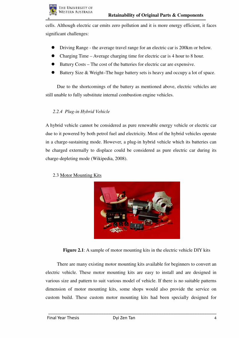
Figure 2.1: A sample of motor mounting kits in the electric vehicle DIY kits
There are many existing motor mounting kits available for beginners to convert an
electric vehicle. These motor mounting kits are easy to install and are designed in
various size and pattern to suit various model of vehicle. If there is no suitable patterns
dimension of motor mounting kits, some shops would also provide the service on
custom build. These custom motor mounting kits had been specially designed for

+ Retainability of Original Parts & Components
______________________________________________________________________
Final Year Thesis Dyi Zen Tan 5
particular model of vehicle and thus it only take less than an hour to mount the electric
motor in the engine compartment. However, these ready-to-go motor mounting kits has
an inflexible design which will limit the liberty to install other parts and components in
the engine compartment.
2.3.1 Rear Support Motor Mounts.
The rear support motor mounts is to support the rear side of the motor or the side
which opposite to the motor drive connection. There are two types of rear supports
motor mounts available for converted electric vehicle. The first type of the motor
mounts is the middle style motor mounts. This middle style motor mounts cradle the
rear side of the electric motor by clamping around the motor middle. The middle type
motor mounts are preferable for the in-line engine style vehicle. On the other hand,
another type of rear support mounts – the plate style mounts is suitable for a transverse
engine vehicle. The plate style mounts is a mounts with plate face to be bolted on the
opposite end face of the motors drive shaft.
Figure 2.2: The two types of rear support mounts
2.3.2 Front Motor Support Mounts
The front motor support mounts is used to mount the electric motor to the original
transmission bell housing. The most common front support mounts available in the
markets is adapter plate mounts. The precision of high accuracy dimension and patterns

+ Retainability of Original Parts & Components
______________________________________________________________________
Final Year Thesis Dyi Zen Tan 6
of the adapter plate with the transmission bell is very crucial, especially the bolt holes
positions for both transmission bell and motor. Most adapter plate are made of
aluminium in order to have minimum weight.
Figure 2.3: Different dimensions and patterns of adapter plate from motor mounting
kits
2.3.3 Coupling
The coupling is a crucial part of motor mounts to lock the motor shaft with the
transmission shaft in order to transfer motor propulsion to the wheel. Therefore, a
coupling requires high mechanical strength to sustain for the high rotation per minute
(rpm) and high torque application. As a result, most coupling is made of steel. There are
many kinds of coupling available in the market: Set screw coupling, shrink fit coupling
and taper lock hub.
2.3.3.1 Set Screw Coupling
Set screw coupling is a coupling with set screw opening. When the coupling has
held the motor shaft, the set screw will be screwed in the set screw opening or thread
holes to tighten the motor shaft. However, according to the Brown and Prange (1993),
the set screw coupling is not safe to use as it will fail catastrophically.
Figure 2.4: A coupling with six set screw opening.

+ Retainability of Original Parts & Components
______________________________________________________________________
Final Year Thesis Dyi Zen Tan 7
2.3.3.2 Shrink Fit Coupling
Shrink fit coupling has a diameter smaller than the shaft. In order to fit the shaft
into the coupling, either heat the coupling or freeze the shaft to allow heat expansion
phenomena to fit the coupling to the shaft. However, this technique is nearly impossible
to remove apart once it in place.
Figure 2.5: Shrink fit coupling for transmission shaft
2.3.3.3 Tapper Lock Hub
The taper lock hub includes a hub and a bushing. The hub inner surface is tapered,
which slides over a matching to the tapered bushing. The bushing has a split with an
outer diameter of slightly larger than the inner surface of the hub. When the bushing had
put in the motor shaft, bolts were used to draw the bushing into the hub. Since the outer
diameter of the bushing is larger than the hub, when the bushing was drawn into the hub,
the split of the bushing will be squeezed to close and the bushing will lock to the motor
shaft tightly. This technique is very secure and could be remove easily for maintenance.
Figure 2.6: A taper lock hub with a bushing.
+ Retainability of Original Parts & Components
______________________________________________________________________
Final Year Thesis Dyi Zen Tan 8
2.4 Existing University REV Project
2.4.1 Two-seater Renewable Energy Vehicle by The University of South Australia
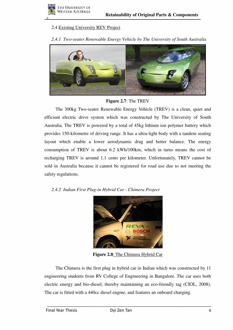
Figure 2.7: The TREV
The 300kg Two-seater Renewable Energy Vehicle (TREV) is a clean, quiet and
efficient electric drive system which was constructed by The University of South
Australia. The TREV is powered by a total of 45kg lithium ion polymer battery which
provides 150-kilometre of driving range. It has a ultra-light body with a tandem seating
layout which enable a lower aerodynamic drag and better balance. The energy
consumption of TREV is about 6.2 kWh/100km, which in turns means the cost of
recharging TREV is around 1.1 cents per kilometer. Unfortunately, TREV cannot be
sold in Australia because it cannot be registered for road use due to not meeting the
safety regulations.
2.4.2 Indian First Plug-in Hybrid Car - Chimera Project
Figure 2.8: The Chimera Hybrid Car
The Chimera is the first plug in hybrid car in Indian which was constructed by 11
engineering students from RV College of Engineering in Bangalore. The car uses both
electric energy and bio-diesel, thereby maintaining an eco-friendly tag (CIOL, 2008).
The car is fitted with a 440cc diesel engine, and features an onboard charging.
+ Retainability of Original Parts & Components
______________________________________________________________________
Final Year Thesis Dyi Zen Tan 9
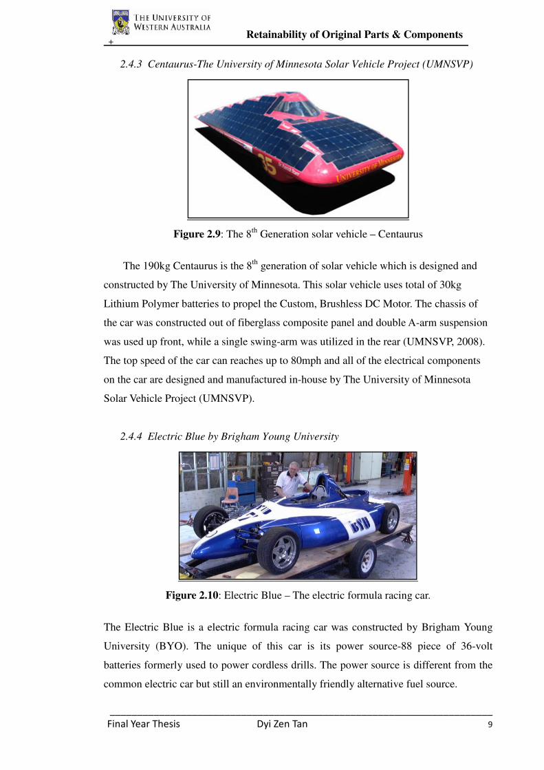
2.4.3 Centaurus-The University of Minnesota Solar Vehicle Project (UMNSVP)
Figure 2.9: The 8th
Generation solar vehicle – Centaurus
The 190kg Centaurus is the 8th
generation of solar vehicle which is designed and
constructed by The University of Minnesota. This solar vehicle uses total of 30kg
Lithium Polymer batteries to propel the Custom, Brushless DC Motor. The chassis of
the car was constructed out of fiberglass composite panel and double A-arm suspension
was used up front, while a single swing-arm was utilized in the rear (UMNSVP, 2008).
The top speed of the car can reaches up to 80mph and all of the electrical components
on the car are designed and manufactured in-house by The University of Minnesota
Solar Vehicle Project (UMNSVP).
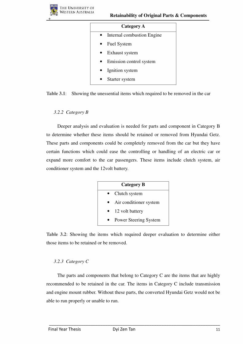
2.4.4 Electric Blue by Brigham Young University
Figure 2.10: Electric Blue – The electric formula racing car.
The Electric Blue is a electric formula racing car was constructed by Brigham Young
University (BYO). The unique of this car is its power source-88 piece of 36-volt
batteries formerly used to power cordless drills. The power source is different from the
common electric car but still an environmentally friendly alternative fuel source.

+ Retainability of Original Parts & Components
______________________________________________________________________
Final Year Thesis Dyi Zen Tan 10
3. Retainability of Original Parts and Components for Hyundai Getz
3.1 Chapter Overview
This chapter covers the substitution of electric motor instead of internal
combustion engine in the Hyundai Getz. Evaluation of unwanted original parts and
components from Hyundai Getz is required to determine which components were
needed to be removed and which components were needed to retain. A motor mount has
to be designed and constructed to attach the electric motor into the car to move the car.
3.2 Methodology
In order to convert an existing internal combustion engine vehicle to an electric
car, some original parts and components from the car must be removed. There are two
reasons why these unwanted or unused parts and components have to be removed. The
first reason is to provide more space for the installation of new electrical parts and
components for an electric car. Another reason for unwanted parts removal is to lower
the overall weight of the vehicle in order to meet higher efficiency.
The original parts and components in the Hyundai Getz can be grouped into three
categories, A, B and C category. The parts and components which belong to category A
are highly unwanted as most of these parts and components are only necessary for
internal combustion engine vehicle but not electric car. Category B belongs to parts and
components which remove or retain these components are to be decided. The parts
and components that belong to Category C are highly recommended to be retained in
the car.
3.2.1 Category A
In order to minimize the weight of the converted vehicle and supply enough space
for electric motor installation, some unessential items from Hyundai Getz had to be
removed. These parts include the internal combustion engine, engine mounts, exhaust
system, fuel system, ignition system and starter system. All of these parts and
components were removed and weighted for calculation of front to rear vehicle weight
distribution.
+ Retainability of Original Parts & Components
______________________________________________________________________
Final Year Thesis Dyi Zen Tan 11
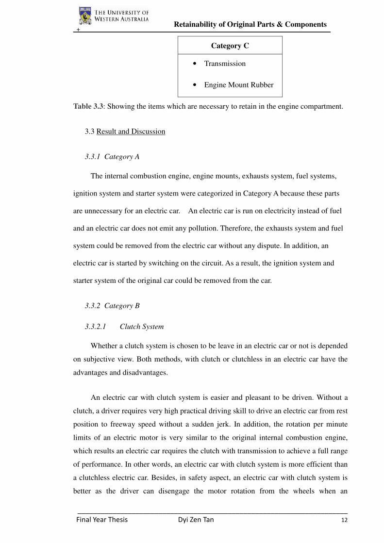
Category A
• Internal combustion Engine
• Fuel System
• Exhaust system
• Emission control system
• Ignition system
• Starter system
Table 3.1: Showing the unessential items which required to be removed in the car
3.2.2 Category B
Deeper analysis and evaluation is needed for parts and component in Category B
to determine whether these items should be retained or removed from Hyundai Getz.
These parts and components could be completely removed from the car but they have
certain functions which could ease the controlling or handling of an electric car or
expand more comfort to the car passengers. These items include clutch system, air
conditioner system and the 12volt battery.
Category B
• Clutch system
• Air conditioner system
• 12 volt battery
• Power Steering System
Table 3.2: Showing the items which required deeper evaluation to determine either
those items to be retained or be removed.
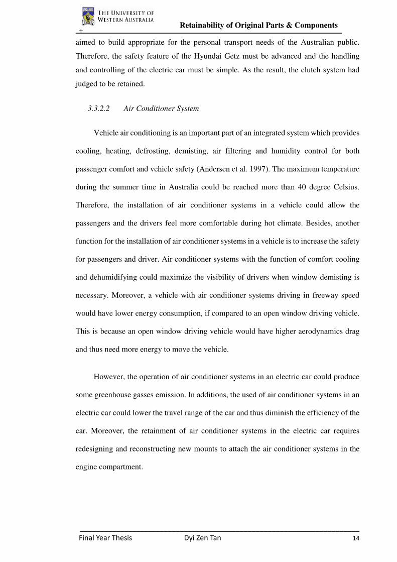
3.2.3 Category C
The parts and components that belong to Category C are the items that are highly
recommended to be retained in the car. The items in Category C include transmission
and engine mount rubber. Without these parts, the converted Hyundai Getz would not be
able to run properly or unable to run.
+ Retainability of Original Parts & Components
______________________________________________________________________
Final Year Thesis Dyi Zen Tan 12
Category C
• Transmission
• Engine Mount Rubber
Table 3.3: Showing the items which are necessary to retain in the engine compartment.
3.3 Result and Discussion
3.3.1 Category A
The internal combustion engine, engine mounts, exhausts system, fuel systems,
ignition system and starter system were categorized in Category A because these parts
are unnecessary for an electric car. An electric car is run on electricity instead of fuel
and an electric car does not emit any pollution. Therefore, the exhausts system and fuel
system could be removed from the electric car without any dispute. In addition, an
electric car is started by switching on the circuit. As a result, the ignition system and
starter system of the original car could be removed from the car.
3.3.2 Category B
3.3.2.1 Clutch System
Whether a clutch system is chosen to be leave in an electric car or not is depended
on subjective view. Both methods, with clutch or clutchless in an electric car have the
advantages and disadvantages.
An electric car with clutch system is easier and pleasant to be driven. Without a
clutch, a driver requires very high practical driving skill to drive an electric car from rest
position to freeway speed without a sudden jerk. In addition, the rotation per minute
limits of an electric motor is very similar to the original internal combustion engine,
which results an electric car requires the clutch with transmission to achieve a full range
of performance. In other words, an electric car with clutch system is more efficient than
a clutchless electric car. Besides, in safety aspect, an electric car with clutch system is
better as the driver can disengage the motor rotation from the wheels when an

+ Retainability of Original Parts & Components
______________________________________________________________________
Final Year Thesis Dyi Zen Tan 13
emergency incident such as under power was occurred. Another advantage of retaining
clutch system in an electric car is to minimize the possibility of the gears inside the
transmission been worn out.
On the other hand, about twelve kilograms of weight could be saved from the
electric car if the clutch system is removed. The lost of weight from the removal of the
clutch system could be substituted by installing more batteries into the electric car. By
installing more batteries into the electric car, the travel range of the car could be
extended when the car is fully charge.
Retain Clutch System
Advantages Disadvantages
� Easier handing on the car
� High efficiency
� Minimize gears wear in the transmission
� Safety feature –disengage motor from
wheel when incident happens
� Increase the weight of the
vehicle
Table 3.4: Advantages and Disadvantages of an electric car which retaining the clutch
system
Remove Clutch System
Advantages Disadvantages
� Save more weight from the vehicle
� More batteries could be installed in the
vehicle due to weight loss of the clutch
system
� The travel range of a fully charged electric
car could be extended.
� Low efficiency
� Gears wear in the transmission
is more likely to happen
Table 3.5: Advantages and Disadvantages of an electric car without the clutch system
In this renewable energy vehicle project, the converted electric Hyundai Getz is
+ Retainability of Original Parts & Components
______________________________________________________________________
Final Year Thesis Dyi Zen Tan 14
aimed to build appropriate for the personal transport needs of the Australian public.
Therefore, the safety feature of the Hyundai Getz must be advanced and the handling
and controlling of the electric car must be simple. As the result, the clutch system had
judged to be retained.
3.3.2.2 Air Conditioner System
Vehicle air conditioning is an important part of an integrated system which provides
cooling, heating, defrosting, demisting, air filtering and humidity control for both
passenger comfort and vehicle safety (Andersen et al. 1997). The maximum temperature
during the summer time in Australia could be reached more than 40 degree Celsius.
Therefore, the installation of air conditioner systems in a vehicle could allow the
passengers and the drivers feel more comfortable during hot climate. Besides, another
function for the installation of air conditioner systems in a vehicle is to increase the safety
for passengers and driver. Air conditioner systems with the function of comfort cooling
and dehumidifying could maximize the visibility of drivers when window demisting is
necessary. Moreover, a vehicle with air conditioner systems driving in freeway speed
would have lower energy consumption, if compared to an open window driving vehicle.
This is because an open window driving vehicle would have higher aerodynamics drag
and thus need more energy to move the vehicle.
However, the operation of air conditioner systems in an electric car could produce
some greenhouse gasses emission. In additions, the used of air conditioner systems in an
electric car could lower the travel range of the car and thus diminish the efficiency of the
car. Moreover, the retainment of air conditioner systems in the electric car requires
redesigning and reconstructing new mounts to attach the air conditioner systems in the
engine compartment.

+ Retainability of Original Parts & Components
______________________________________________________________________
Final Year Thesis Dyi Zen Tan 15
Retain Air Conditioner Systems
Advantages Disadvantages
� Increase comfort to passenger
� Increase vehicle safety, due to
higher visibility when stem has
fogged the windows
� Lower energy consumption in
freeway speed
� Need to reserve space in the engine
compartment for air conditioner
systems
� Need to redesign a mount to attach
air conditioner systems in the
engine compartment
� Produce greenhouse gasses
� More energy consumption if air
conditioner systems is used
improperly
Table 3.6: Advantages and Disadvantages of an electric car which retaining the air
conditioner system
Remove Air Conditioner Systems
Advantages Disadvantages
� Zero pollution
� More space in engine compartment
� Higher efficiency and the travel range
of the vehicle is higher
� Driver and passengers are less
comfortable
� Low safety due to low visibility when
window has fogged
� Use more energy when the vehicle is
driving on freeway speed due to
increase of aerodynamic drag
Table 3.7: Advantages and Disadvantages of an electric car without the air conditioner
systems
Although both methods; retain the air conditioner systems in an electric car and
remove air conditioner systems from the electric car have its own advantages and
disadvantages, the converted Hyundai Getz was selected to retain the air conditioner
systems. In spite of retaining air conditioner systems in Hyundai Getz requires more
time and effort to redesign mounts in the engine compartment, it is worthy as this
method could increase the vehicle safety and expand passengers comfort.
+ Retainability of Original Parts & Components
______________________________________________________________________
Final Year Thesis Dyi Zen Tan 16
3.3.2.3 12 Volt Battery
The original function of the 12 volt battery from the Hyundai Getz is to generate
electricity to the ignition systems and order electrical parts such as head lights and air
conditioner systems. However, the converted Hyundai Getz had aimed to install forty
five blocks of lithium-ion battery to run the electric motor. The operating voltage for
each block of lithium-ion battery is 3.2volt, where total operating voltage of 144volts
are generated from 45 blocks of lithium-ion battery. These high voltage generated from
lithium-ion batteries are high enough to substitute the original 12 volt battery.
However, the 12 volt battery had been chosen to be retained in the converted
Hyundai Getz, inasmuch as the retainment of 12 volt battery could expand the travel
range of the electric car due to all the lithium-ion batteries could concentrate on
generating electricity to electric motor while the 12 volt battery generate electricity to
order electrical components.
3.3.2.4 Power Steering Systems
Power steering is a system that to reduce the input force required to turn or to steer
the road wheels by using external power source. An electric car could be driven without
power steering systems but it would be difficult for the driver to maneuver the vehicle
wheels at low speeds. Since the converted Hyundai Getz is build appropriate for the
personal transport needs of the Australian public, the power steering systems was
decided be retained in the converted car to enable the car is easy and pleasant to be
driven.
3.3.3 Category C
3.3.3.1 Transmission
Transmission or commonly known as gearbox is used to provide a speed-torque
conversion for a vehicle. With the installation of transmission, a slower but more
forceful output could be done from a high rotation motor. When a car is traveling slowly
or moving from standstill speed, a greater torque is required. Therefore, transmission is

+ Retainability of Original Parts & Components
______________________________________________________________________
Final Year Thesis Dyi Zen Tan 17
necessary for a vehicle to transforms a low speeds rotation motor into a high torque
rotation. In additions, transmission is needed in a car to ensure the electric motor is
operating within its limits when the vehicle is running in a freeway speed.
3.3.3.2 Engine Mount Rubber
Engine mount rubber is an important vehicle component which is used to isolate
the vehicle structure from vibration of the engine or electric motor. Without the engine
mount rubber, the passengers and the driver of the vehicle might be uncomfortable due
to the vibration from high rotation motor. Since the converted Hyundai Getz is a brand
new car, it is not necessary to replace a new pair of engine mount rubber. Although an
electric motor is generally lighter and less vibration than an internal combustion engine,
the engine mount rubbers are still necessary to retain in the engine compartment in order
to isolate vehicle structure from the vibration of motor.
Figure 3.1: Sample picture of engine mount rubbers.
+ Design of Motor Mounts for an Electric Motor
______________________________________________________________________
Final Year Thesis Dyi Zen Tan 18
4. Design of Motor Mounts for an Electric Motor
4.1 Chapter Overview
This chapter covers the design and modeling of the motor mounts for attaching
the electric motor in the engine compartment. Since the converted Hyundai Getz is
proposed to register as a licensed road car, the entire design of motor mounts for the
car must conform under the restraint of certain regulations and rules.
4.2 Aims of the REV Project
The constraints imposed by the aims of the project are shown as follow:
• Design must be fully compliant with the National Regulations
• Design must be as simple as possible with low fabrication cost
4.3 Constraints
The converted electric car in this project is aimed to register as a licensed road
vehicle. Therefore, the design of the motor mounts for Hyundai Getz must be strictly
conform to design rules and regulations which are nationally accepted in Australia.
There are few nationally accepted guidelines which have been introduced by The
Australian Motor Vehicle Certification Board Working for the installation of electric
drives in Australia. These guidelines include National Code of Practice for Light Vehicle
Construction and Modification, Australian Vehicle Standards Rules 1999 (AVSR) and
with Australian Design Rules (ADR).
However, neither Australia Design Rules nor other standards have relevant
regulations or rules that restraint the design and construction of motor mounts. In
order to design a qualified motor mounts for Hyundai Getz, a clearer and deeper
understanding on original engine mounts should be existed.
+ Design of Motor Mounts for an Electric Motor
______________________________________________________________________
Final Year Thesis Dyi Zen Tan 19
4.3.1 The Main Functions of Engine Mounts
There are two main functions of an engine mount in a vehicle. Along with securing
the engine in place, the engine mounts have another equally important function, which
is to isolate the whole vehicle from engine vibration or shaking. Engine mounts allow
the rotation between engine shaft and transmission shaft, but still assist to keep the
engine and transmission in the proper alignment. One of the critical parts of the engine
mounts is engine mount rubber. The main function of the engine mounts rubber is to
perform as a damper to damp the vibration and noise created by engine.
4.3.2 Requirements of Qualified Motor Mounts Based on the Original Engine
Mounts
As there do not have the relevant codes or regulations that restraint the design of
motor mounts for an electric car, some assumption had to be made in order to design a
qualified motor mounts. Firstly, the motor mounts must be tough enough to secure the
electric motor with the transmission in the engine compartment. Secondly, the engine
mounts have to be designed to isolate the motor vibration from being transfer to the
vehicle structure.
The first requirement of building a qualified motor mounts is to ensure the motor
mounts must attach the electric motor tightly in the engine compartment with the
transmission. However, the motor mounts are not designed to sustain a high frontal
impact. The original engine and transmission of Hyundai Getz were designed to drop
out of the bottom of the engine compartment when a frontal impact occurred. This
design is used to prevent the intrusion of the engine and transmission into the
passenger compartment and thus lower the risk of the driver and passengers when
accident is occurred. The design of very high strength motor mounts to sustain for
frontal impact was considered as undesirable. A motor mounts which are tough
enough to secure the motor firmly with the transmission in the engine compartment
could be considered as a qualified motor mounts.

+ Design of Motor Mounts for an Electric Motor
______________________________________________________________________
Final Year Thesis Dyi Zen Tan 20
Figure 4.1: The Engine Cradle is designed to drop the engine and transmission out of
the bottom of engine compartment (Cincurak 2008).
Figure 4.2: During the frontal impact, the front end of the vehicle continues to collapse
and absorb energy as the engine cradle continues to move back and
down,( Cincurak 2008).
The second requirement of building a qualified motor mounts is to ensure the
motor mounts are able to isolate or lessen the vibration of motor to the vehicle
structure. One of the advantages of an electric motor is the electric motor is much
silent and less vibration during operations if compared with an internal combustion
engine. Therefore, the original engine mount rubbers in Hyundai Getz are well enough
to perform as dampers to damp the vibration of the electric motor. The original engine
mount rubbers were chosen to be retained in the converted Hyundai Getz as explained
at section 3.3.3.2. As a result, the second requirement of the design of motor mounts
for this project is to ensure the motor mounts are able to transfer the motor vibration
to the engine mount rubbers to be damped

+ Design of Motor Mounts for an Electric Motor
______________________________________________________________________
Final Year Thesis Dyi Zen Tan 21
4.4 Design and construction of Motor Mounts
Motor mounts are used to secure the electric motor firmly with the transmission
in the engine compartment. In regard to the motor attachment, the motor shaft have
to be aligned with the transmission shaft all the time while the motor mounts are able
to transfer the motor vibration to the engine mount rubber to be damped. There
design of motor mounts had been split up to four parts :
� Front support- motor to transmission adapter plate
� Rear support for electric motor
� Mounting bar for extra support of motor mounts
� Motor Shaft with Transmission shaft connection via coupling
A complete motor mounts design must be covered by four elements above and
deeper evaluation on these four elements is needed. The design and construction of
each part of the elements above will be discussed below in sequence.
4.4.1 Design and Construction of Frontal Support
The main function of the front support of the electric motor (adapter plate) is to
fix the motor and the transmission tightly together to allow motor shaft turns the
transmission shaft smoothly. The adapter plate has to be bolted on both the front of
the motor and the front face of the transmission bell housing.
4.4.1.1 Methodology of Front Support Design
There were four steps to be taken to analyse in order to design and construct an
adapter plate:
1. A critical distance between the motor shaft and transmission shaft had to be
calculated.
2. The frontal shape of the transmission bell housing had to be recorded.
3. The location of the bolts holes and screw holes of the frontal of the transmission
bell housing and the electric motor has to be determined
+ Design of Motor Mounts for an Electric Motor
______________________________________________________________________
Final Year Thesis Dyi Zen Tan 22
4. The centre point for the adapter plate had to be determined.
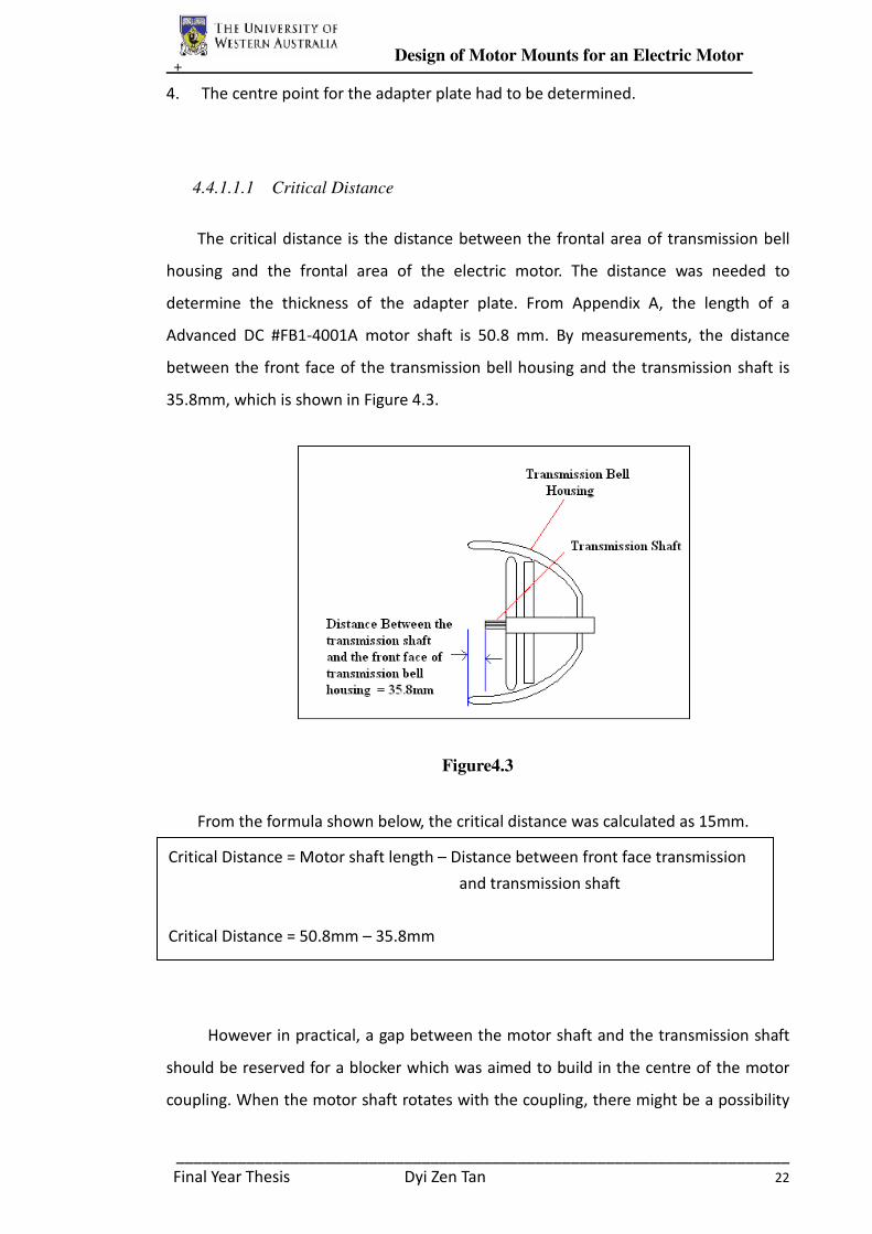
4.4.1.1.1 Critical Distance
The critical distance is the distance between the frontal area of transmission bell
housing and the frontal area of the electric motor. The distance was needed to
determine the thickness of the adapter plate. From Appendix A, the length of a
Advanced DC #FB1-4001A motor shaft is 50.8 mm. By measurements, the distance
between the front face of the transmission bell housing and the transmission shaft is
35.8mm, which is shown in Figure 4.3.
Figure4.3
From the formula shown below, the critical distance was calculated as 15mm.
However in practical, a gap between the motor shaft and the transmission shaft
should be reserved for a blocker which was aimed to build in the centre of the motor
coupling. When the motor shaft rotates with the coupling, there might be a possibility
Critical Distance = Motor shaft length – Distance between front face transmission
and transmission shaft
Critical Distance = 50.8mm – 35.8mm
= 15mm

+ Design of Motor Mounts for an Electric Motor
______________________________________________________________________
Final Year Thesis Dyi Zen Tan 23
that the coupling might slides in and out from the motor shaft. With the design of
locating a blocker in the centre of the coupling, the possibility of coupling slides could
be prevented.
Therefore, a gap of 5mm was reserved for the coupling design requirement in
order to prevent coupling sliding in and out from the motor shaft. The confirmed
critical distance of the motor and transmission is 20mm, which indicate the thickness
of the adapter plate is 20mm.
Figure 4.4: The gap distance and critical distance between motor and transmission.
4.4.1.1.2 Determination of the Shape of Adapter Plate and the Transmission Bolts
Hole Location
The shape of the adapter plate had to be determined to ensure the adapter plate
is large enough to cover all frontal area of the transmission bell housing and the frontal
area of the electric motor. However, the method on how to determine the shape of the
adapter plate was complicated as the shape pattern of the front face of the
transmission is irregular as shown in Figure 4.5. A primitive method (stencil and
mimeograph) had been chosen to record the front pattern or template of the
transmission due to its easiness, high accuracy and rapidty.
Firstly, a large cardboard and some watercolour were prepared. Secondly, the front
face of the transmission was painted by watercolour to act as a stencil. When the front
face of the transmission was fully painted, the large cardboard was attached firmly and
+ Design of Motor Mounts for an Electric Motor
______________________________________________________________________
Final Year Thesis Dyi Zen Tan 24
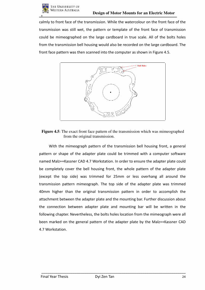
calmly to front face of the transmission. While the watercolour on the front face of the
transmission was still wet, the pattern or template of the front face of transmission
could be mimeographed on the large cardboard in true scale. All of the bolts holes
from the transmission bell housing would also be recorded on the large cardboard. The
front face pattern was then scanned into the computer as shown in Figure 4.5.
Figure 4.5: The exact front face pattern of the transmission which was mimeographed
from the original transmission.
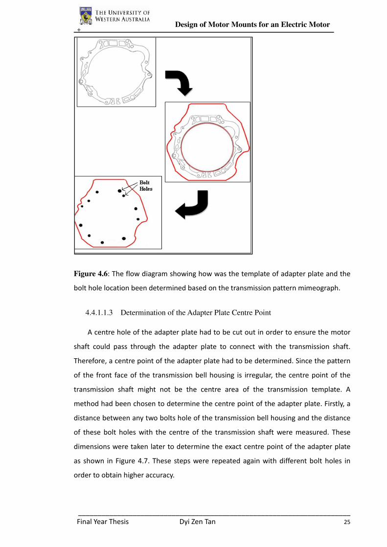
With the mimeograph pattern of the transmission bell housing front, a general
pattern or shape of the adapter plate could be trimmed with a computer software
named Malz++Kassner CAD 4.7 Workstation. In order to ensure the adapter plate could
be completely cover the bell housing front, the whole pattern of the adapter plate
(except the top side) was trimmed for 25mm or less overhang all around the
transmission pattern mimeograph. The top side of the adapter plate was trimmed
40mm higher than the original transmission pattern in order to accomplish the
attachment between the adapter plate and the mounting bar. Further discussion about
the connection between adapter plate and mounting bar will be written in the
following chapter. Nevertheless, the bolts holes location from the mimeograph were all
been marked on the general pattern of the adapter plate by the Malz++Kassner CAD
4.7 Workstation.
+ Design of Motor Mounts for an Electric Motor
______________________________________________________________________
Final Year Thesis Dyi Zen Tan 25
Figure 4.6: The flow diagram showing how was the template of adapter plate and the
bolt hole location been determined based on the transmission pattern mimeograph.
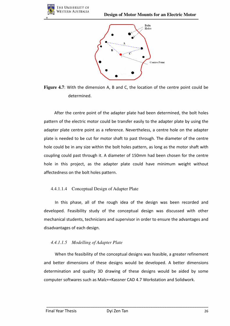
4.4.1.1.3 Determination of the Adapter Plate Centre Point
A centre hole of the adapter plate had to be cut out in order to ensure the motor
shaft could pass through the adapter plate to connect with the transmission shaft.
Therefore, a centre point of the adapter plate had to be determined. Since the pattern
of the front face of the transmission bell housing is irregular, the centre point of the
transmission shaft might not be the centre area of the transmission template. A
method had been chosen to determine the centre point of the adapter plate. Firstly, a
distance between any two bolts hole of the transmission bell housing and the distance
of these bolt holes with the centre of the transmission shaft were measured. These
dimensions were taken later to determine the exact centre point of the adapter plate
as shown in Figure 4.7. These steps were repeated again with different bolt holes in
order to obtain higher accuracy.
+ Design of Motor Mounts for an Electric Motor
______________________________________________________________________
Final Year Thesis Dyi Zen Tan 26
Figure 4.7: With the dimension A, B and C, the location of the centre point could be
determined.
After the centre point of the adapter plate had been determined, the bolt holes
pattern of the electric motor could be transfer easily to the adapter plate by using the
adapter plate centre point as a reference. Nevertheless, a centre hole on the adapter
plate is needed to be cut for motor shaft to past through. The diameter of the centre
hole could be in any size within the bolt holes pattern, as long as the motor shaft with
coupling could past through it. A diameter of 150mm had been chosen for the centre
hole in this project, as the adapter plate could have minimum weight without
affectedness on the bolt holes pattern.
4.4.1.1.4 Conceptual Design of Adapter Plate
In this phase, all of the rough idea of the design was been recorded and
developed. Feasibility study of the conceptual design was discussed with other
mechanical students, technicians and supervisor in order to ensure the advantages and
disadvantages of each design.
4.4.1.1.5 Modelling of Adapter Plate
When the feasibility of the conceptual designs was feasible, a greater refinement
and better dimensions of these designs would be developed. A better dimensions
determination and quality 3D drawing of these designs would be aided by some
computer softwares such as Malz++Kassner CAD 4.7 Workstation and Solidwork.
+ Design of Motor Mounts for an Electric Motor
______________________________________________________________________
Final Year Thesis Dyi Zen Tan 27
4.4.1.1.6 Material Selection and Fabrication of Adapter Plate
The finalized adapter plate design drawing was submitted to the Electrical
Engineering Workshop for fabrication. A discussion and analysis had done with
technician Ken in order to determine the available material and machines used to
fabricate the finalized design. King Rich vertical milling machine with the aid of rotary
table were used to fabricate adapter plate.
4.4.1.2 Result and Discussion for Adapter Plate
4.4.1.2.1 Initial Design of Adapter Plate
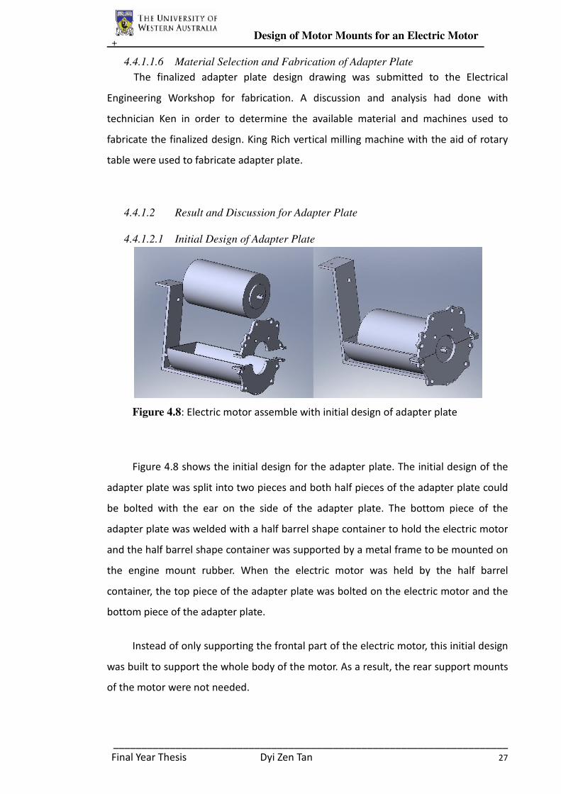
Figure 4.8: Electric motor assemble with initial design of adapter plate
Figure 4.8 shows the initial design for the adapter plate. The initial design of the
adapter plate was split into two pieces and both half pieces of the adapter plate could
be bolted with the ear on the side of the adapter plate. The bottom piece of the
adapter plate was welded with a half barrel shape container to hold the electric motor
and the half barrel shape container was supported by a metal frame to be mounted on
the engine mount rubber. When the electric motor was held by the half barrel
container, the top piece of the adapter plate was bolted on the electric motor and the
bottom piece of the adapter plate.
Instead of only supporting the frontal part of the electric motor, this initial design
was built to support the whole body of the motor. As a result, the rear support mounts
of the motor were not needed.

+ Design of Motor Mounts for an Electric Motor
______________________________________________________________________
Final Year Thesis Dyi Zen Tan 28
However, this initial design had been rejected due to the possibility that the
water might be stored on the half barrel container during rainy day. The catchment of
water on the barrel container would be resulted on short circuit of the electric motor.
In addition, the fabrication with this design was complex as there were many little
parts which need to be jointed in this design. Moreover, the material cost of this design
might be very high due to this design required large amount of material to be built,
which will also increase the weight of the mounts. Due to the safety reason and high
fabrication cost, this design had been rejected.
Initial Design
Advantages Disadvantages
• High strength
• Support whole part of Motor
• Safety problem – could stored water
• High fabrication cost
• Overall weight is heavy
Table 4.1: The advantages and disadvantages of the initial design.
4.4.1.2.2 Final Design of Adapter Plate
Table 4.2
The final design of the adapter plate is much smaller, lighter and simpler than the
earlier idea. This simple design was only require a piece of square aluminium alloy
Final Dimension of the Adapter Plate
Thickness 20mm
Maximum
Width
360mm
Maximum
Height
390mm
Centre Hole
Diameter
150mm
Transmission
Bolt Holes
Four M12 Bolts and 8
M10 Bolts
Motor Bolt
Holes
Four M8 Screw

+ Design of Motor Mounts for an Electric Motor
______________________________________________________________________
Final Year Thesis Dyi Zen Tan 29
plate to be fabricated. The design is simple but well enough to hold the motor with the
transmission tightly. The design is lighter if compared with initial design and less
fabrication cost and techniques to be constructed.
A total of four M12 Bolts and eight M10 Bolts and Nuts were used to secure the
adapter plate with the transmission bell housing. These bolts were original used to
secure the internal combustion engine with the transmission bell. The electric motor
used in this project is only half the weight of the original engine and an electric motor
is generally less vibration than an internal combustion engine. Therefore, the original
bolts which used to secure the engine and transmission were confirmed strong enough
to hold the adapter plate tightly with the transmission bell.
The front face of the electric motor was originally equipped with four 8mm screw
holes which were designed to be held by four M8 screw. As a result, four high tensile
stainless steel (M8) socket head cap screws were used to secure the adapter plate with
the electric motor.
Figure 4.9: Figure showing how the bolts secure the adapter plate with the motor and
transmission.
Although the motor shaft with coupling could past through a minimum diameter
of 80mm for the centre hole, the diameter of the adapter plate centre hole was
determined to 150mm. This decision was made to reduce extra weight of the adapter
plate and thus increases the efficiency of the electric car.
+ Design of Motor Mounts for an Electric Motor
______________________________________________________________________
Final Year Thesis Dyi Zen Tan 30
4.4.1.2.3 Material Selection and Fabrication of Adapter Plate
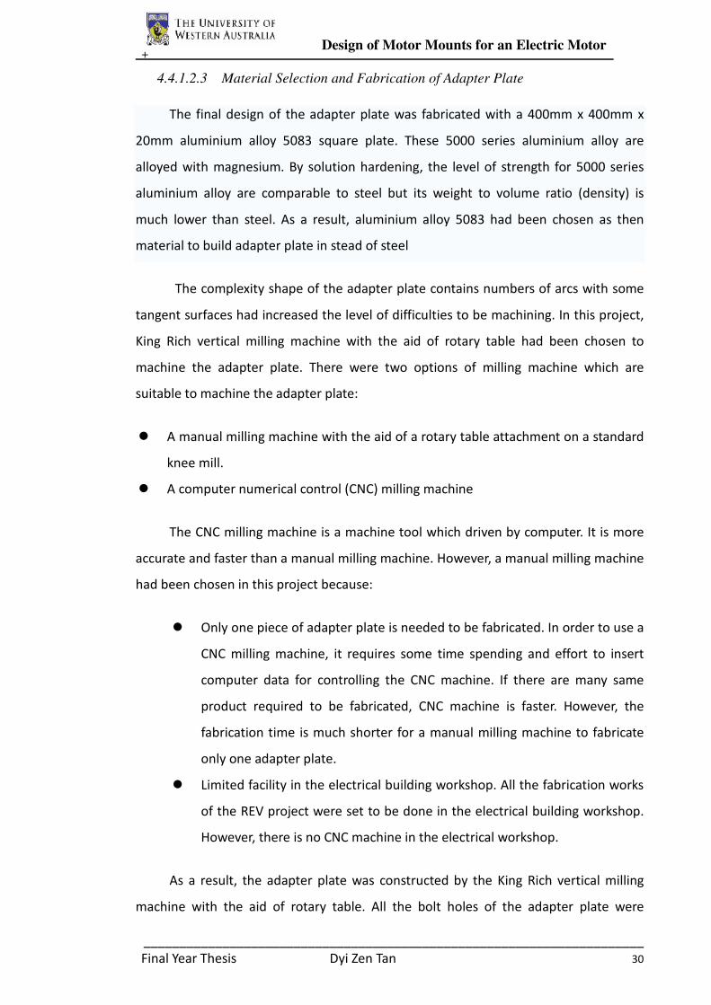
The final design of the adapter plate was fabricated with a 400mm x 400mm x
20mm aluminium alloy 5083 square plate. These 5000 series aluminium alloy are
alloyed with magnesium. By solution hardening, the level of strength for 5000 series
aluminium alloy are comparable to steel but its weight to volume ratio (density) is
much lower than steel. As a result, aluminium alloy 5083 had been chosen as then
material to build adapter plate in stead of steel
The complexity shape of the adapter plate contains numbers of arcs with some
tangent surfaces had increased the level of difficulties to be machining. In this project,
King Rich vertical milling machine with the aid of rotary table had been chosen to
machine the adapter plate. There were two options of milling machine which are
suitable to machine the adapter plate:
� A manual milling machine with the aid of a rotary table attachment on a standard
knee mill.
� A computer numerical control (CNC) milling machine
The CNC milling machine is a machine tool which driven by computer. It is more
accurate and faster than a manual milling machine. However, a manual milling machine
had been chosen in this project because:
� Only one piece of adapter plate is needed to be fabricated. In order to use a
CNC milling machine, it requires some time spending and effort to insert
computer data for controlling the CNC machine. If there are many same
product required to be fabricated, CNC machine is faster. However, the
fabrication time is much shorter for a manual milling machine to fabricate
only one adapter plate.
� Limited facility in the electrical building workshop. All the fabrication works
of the REV project were set to be done in the electrical building workshop.
However, there is no CNC machine in the electrical workshop.
As a result, the adapter plate was constructed by the King Rich vertical milling
machine with the aid of rotary table. All the bolt holes of the adapter plate were

+ Design of Motor Mounts for an Electric Motor
______________________________________________________________________
Final Year Thesis Dyi Zen Tan 31
matched with the bolt holes of the transmission bell and the electric motor.
Figure 4.10: The adapter plate had been fabricated by the vertical milling
machine
In summary, the tasks of the adapter plate are to support the front of the motor
in place with the transmission bell and withstand the opposing torsion force created by
motor shaft. These two tasks are satisfied with the manufacture of one component and
thus the overall weight and complexity of the design of the adapter plate is kept to a
minimum.
4.4.2 Design and Construction of Rear Support
The main function of the rear support of the electric motor is to support the rear
side of the motor. The rear support of the motor was aimed to connect with the engine
mount rubber which located on the side in the engine compartment. Therefore, the
rear support of the motor can also be functioned as transmission medium of motor
vibration to the engine mount rubber.
4.4.2.1 Methodology of Rear Support Design
In order to design the rear support for the electric motor, the vertical distance
and horizontal distance between the electric motor and the location of engine mount
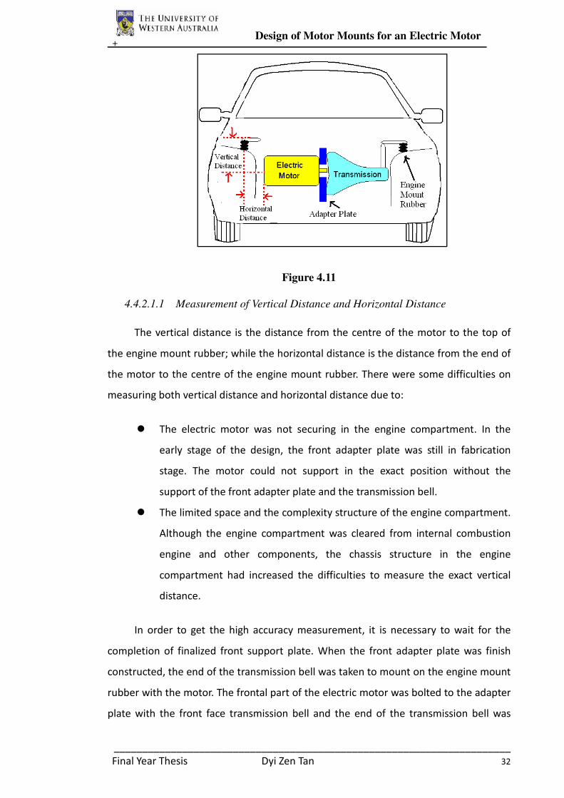
rubber had to be determined. Figure 4.11 shows how was the electric motor secure
with the transmission bell by the front adapter plate and how was the transmission
mounted by the engine mount rubber.
+ Design of Motor Mounts for an Electric Motor
______________________________________________________________________
Final Year Thesis Dyi Zen Tan 32
Figure 4.11
4.4.2.1.1 Measurement of Vertical Distance and Horizontal Distance
The vertical distance is the distance from the centre of the motor to the top of
the engine mount rubber; while the horizontal distance is the distance from the end of
the motor to the centre of the engine mount rubber. There were some difficulties on
measuring both vertical distance and horizontal distance due to:
� The electric motor was not securing in the engine compartment. In the
early stage of the design, the front adapter plate was still in fabrication
stage. The motor could not support in the exact position without the
support of the front adapter plate and the transmission bell.
� The limited space and the complexity structure of the engine compartment.
Although the engine compartment was cleared from internal combustion
engine and other components, the chassis structure in the engine
compartment had increased the difficulties to measure the exact vertical
distance.
In order to get the high accuracy measurement, it is necessary to wait for the
completion of finalized front support plate. When the front adapter plate was finish
constructed, the end of the transmission bell was taken to mount on the engine mount
rubber with the motor. The frontal part of the electric motor was bolted to the adapter
plate with the front face transmission bell and the end of the transmission bell was
+ Design of Motor Mounts for an Electric Motor
______________________________________________________________________
Final Year Thesis Dyi Zen Tan 33
supported by engine mount rubber. Meanwhile, the end of the motor was hung by a
mobile crank. A spirit level was used to confirm the electric motor was in the level
position when hung by mobile crank.
When all of steps mentioned above were set up, the vertical distance and the
horizontal distance could be measured with the aid of ninety degree ruler, cord and
measuring tape. A few people were needed to measure the vertical distance and
horizontal distance in this situation. The final measurement of the vertical and
horizontal distance was listed in Table 4.3.
Vertical Distance 276mm
Horizontal Distance 132mm
Table 4.3
4.4.2.1.2 Conceptual Design, Modelling and Fabrication of Motor Rear Support
Firstly, all the rough idea about the design of rear support were recorded and
sketched in this stage. Next, formal meeting and discussion were held with other
mechanical students and project supervisor to analyse the feasibility of the design. The
eligible conceptual designs were drawn with the aid of Solidworks 2007. A stress
analysis would also be done with ANSYS Work Bench in order to ensure the strength of
the design. Next, the 3D CAD drawings were again discussed with supervisor and
workshop technician for further feasibility study and machining analysis. Machining
analysis in this stage includes material selection, fabrication cost analysis and analysis
on level of fabrication simplicity. There were only one design sample would be chosen
as the final design to be fabricated.
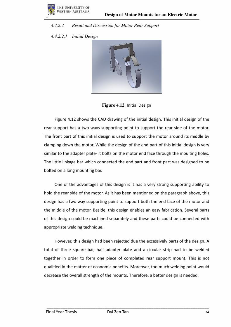
+ Design of Motor Mounts for an Electric Motor
______________________________________________________________________
Final Year Thesis Dyi Zen Tan 34
4.4.2.2 Result and Discussion for Motor Rear Support
4.4.2.2.1 Initial Design
Figure 4.12: Initial Design
Figure 4.12 shows the CAD drawing of the initial design. This initial design of the
rear support has a two ways supporting point to support the rear side of the motor.
The front part of this initial design is used to support the motor around its middle by
clamping down the motor. While the design of the end part of this initial design is very
similar to the adapter plate- it bolts on the motor end face through the moulting holes.
The little linkage bar which connected the end part and front part was designed to be
bolted on a long mounting bar.
One of the advantages of this design is it has a very strong supporting ability to
hold the rear side of the motor. As it has been mentioned on the paragraph above, this
design has a two way supporting point to support both the end face of the motor and
the middle of the motor. Beside, this design enables an easy fabrication. Several parts
of this design could be machined separately and these parts could be connected with
appropriate welding technique.
However, this design had been rejected due the excessively parts of the design. A
total of three square bar, half adapter plate and a circular strip had to be welded
together in order to form one piece of completed rear support mount. This is not
qualified in the matter of economic benefits. Moreover, too much welding point would
decrease the overall strength of the mounts. Therefore, a better design is needed.

+ Design of Motor Mounts for an Electric Motor
______________________________________________________________________
Final Year Thesis Dyi Zen Tan 35
4.4.2.2.2 Improved Design of Rear Support Mount
Figure 4.13 : Improved Design of Rear Support Mount
The subsequent design had some of the unnecessary material removed in order
to reduce the parts to be welded and save weight. In this design, the middle support
clamp was removed and only the rear plate been reserved. The rear plate is welded by
a T-shape mount. This T-shape mount was intended to be bolted on the bottom of a
mounting bar, which attempted to support the entire later half weight of the motor.
However, with the aid of ANSYS stress analysis, the welding joint of the T-shape mount
might not be able to sustain the weight of the motor very well. As a result, further
improvement of the design is needed.
4.4.2.2.3 Final Design of the Rear Support Mount
Table 4.4
Again, the final design of the rear support mount is as simple as the design of the
front adapter plate. It is much smaller, lighter and simpler than the earlier idea. This
simple design was only require a piece of square aluminium alloy plate to be fabricated.
Height 230mm
Top Side Width 70mm
Bottom Side Width 180mm
Thickness 10mm
Bolt Holes 4 x M8 Socket Head Cap
Screw
Material Aluminium Alloy 5083
Series
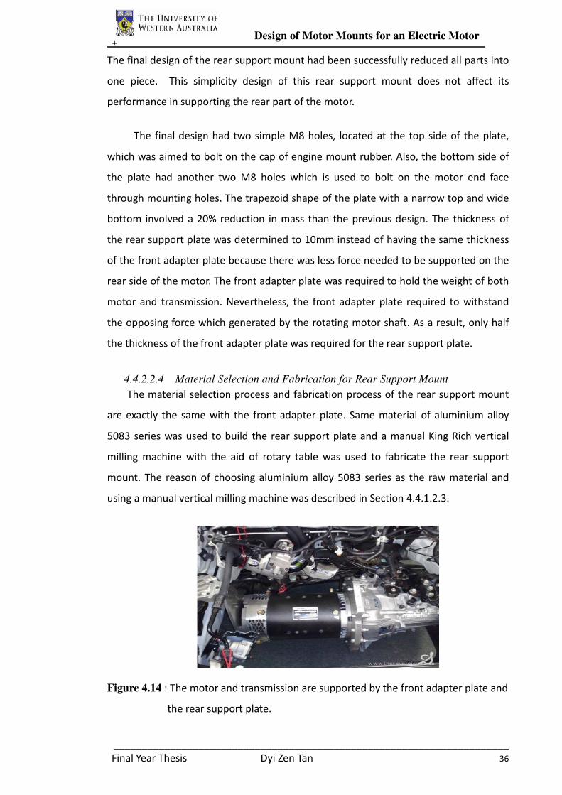
+ Design of Motor Mounts for an Electric Motor
______________________________________________________________________
Final Year Thesis Dyi Zen Tan 36
The final design of the rear support mount had been successfully reduced all parts into
one piece. This simplicity design of this rear support mount does not affect its
performance in supporting the rear part of the motor.
The final design had two simple M8 holes, located at the top side of the plate,
which was aimed to bolt on the cap of engine mount rubber. Also, the bottom side of
the plate had another two M8 holes which is used to bolt on the motor end face
through mounting holes. The trapezoid shape of the plate with a narrow top and wide
bottom involved a 20% reduction in mass than the previous design. The thickness of
the rear support plate was determined to 10mm instead of having the same thickness
of the front adapter plate because there was less force needed to be supported on the
rear side of the motor. The front adapter plate was required to hold the weight of both
motor and transmission. Nevertheless, the front adapter plate required to withstand
the opposing force which generated by the rotating motor shaft. As a result, only half
the thickness of the front adapter plate was required for the rear support plate.
4.4.2.2.4 Material Selection and Fabrication for Rear Support Mount
The material selection process and fabrication process of the rear support mount
are exactly the same with the front adapter plate. Same material of aluminium alloy
5083 series was used to build the rear support plate and a manual King Rich vertical
milling machine with the aid of rotary table was used to fabricate the rear support
mount. The reason of choosing aluminium alloy 5083 series as the raw material and
using a manual vertical milling machine was described in Section 4.4.1.2.3.
Figure 4.14 : The motor and transmission are supported by the front adapter plate and
the rear support plate.
+ Design of Motor Mounts for an Electric Motor
______________________________________________________________________
Final Year Thesis Dyi Zen Tan 37
In summary, the task of the rear support plate is to mount the rear side of the
motor in place, ensure the motor in level and help to transfer the vibration to the
mount rubbers. These three task are satisfied the manufacture of one component, so
the overall weight and complexity of the rear support mount is kept to a minimum.
4.4.3 Design and Construction of Mounting Bar
A mounting bar was aimed to built and mounted on the top of the motor and the
transmission bell housing. Although both the end side of the motor and transmission
bell were supported by the engine mount rubber tightly, the mounting bar was
purposed to strengthen the hold of motor and transmission. Both end side of the
mounting bar were secured on the mount rubber and the middle of the mounting bar
would be bolted on the top of the front adapter plate. Therefore, the mounting bar can
also help to transfer the vibration of motor and transmission to the engine mount
rubber. Nevertheless, the mounting bar was aimed to be built to provide more
mounting base for other electrical parts such as controller box, throttle potentiometer
and air conditioner motor.
4.4.3.1 Methodology of Mounting Bar Design
In order to design the mounting bar for the electric motor, the vertical and
horizontal distance between two engine mount rubbers had to be measure. The
measurement of the vertical and horizontal distance between two mount rubbers is
straight forward as both engine mount rubbers were attached steadily in the engine
compartment. Table XX is listed the vertical and horizontal distance between two
mount rubbers.
Horizontal Distance 945mm
Vertical Distance 105mm
Table 4.5
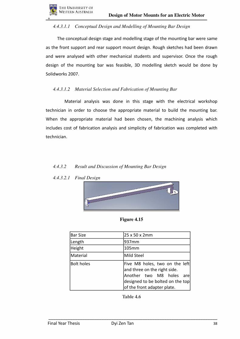
+ Design of Motor Mounts for an Electric Motor
______________________________________________________________________
Final Year Thesis Dyi Zen Tan 38
4.4.3.1.1 Conceptual Design and Modelling of Mounting Bar Design
The conceptual design stage and modelling stage of the mounting bar were same
as the front support and rear support mount design. Rough sketches had been drawn
and were analysed with other mechanical students and supervisor. Once the rough
design of the mounting bar was feasible, 3D modelling sketch would be done by
Solidworks 2007.
4.4.3.1.2 Material Selection and Fabrication of Mounting Bar
Material analysis was done in this stage with the electrical workshop
technician in order to choose the appropriate material to build the mounting bar.
When the appropriate material had been chosen, the machining analysis which
includes cost of fabrication analysis and simplicity of fabrication was completed with
technician.
4.4.3.2 Result and Discussion of Mounting Bar Design
4.4.3.2.1 Final Design
Figure 4.15
Table 4.6
Bar Size 25 x 50 x 2mm
Length 937mm
Height 105mm
Material Mild Steel
Bolt holes Five M8 holes, two on the left
and three on the right side.
Another two M8 holes are
designed to be bolted on the top
of the front adapter plate.
+ Design of Motor Mounts for an Electric Motor
______________________________________________________________________
Final Year Thesis Dyi Zen Tan 39
Base from the previous design experience on the front adapter plate and the rear
support mount, the initial design of the mounting bar is simple and thus the initial
design was well enough to be the final design. A rectangular mild steel bar of 25mm
height x 50mm width with 2mm thickness was chosen to be the main body of the
mounting bar. Since the main functions of the mounting bar are to provide a mounting
base for other electrical parts and to transfer vibration from the motor to the mount
rubber, the requirement strength of the bar is low. Therefore, mild steel bar was
chosen as its price is relatively low compared to higher carbon steel.
The left hand side of the mounting bar was welded with a square 6mm thick
plate to be bolted on the mount rubber cap; while the right hand side of the bar was
welded with another 105mm long mild steel bar to be bolted on the top of the mount
rubber cap. MIG welding was chosen to weld this joint due to its high versatility and
lower welding time.
In summary, the tasks of the mounting bar are to act as a mounting base for
other electrical parts, strengthen the motor mounts and increase the efficiency to
transfer the vibration of the motor to the mount rubbers. These three tasks are
satisfied with just a simple design of rectangular bar with legs to be bolted on the
mount rubber caps.
4.4.4 Design and Construction of Coupling
Coupling design is one of the critical parts for motor mounts design. A coupling
is used to connect the motor shaft to the transmission shaft which enables the motor
to turn the transmission shaft and thus moves the vehicle. Since the dimension and
shaft pattern of the motor shaft is different with the transmission shaft, two different
patterns of couplings were needed to be design respectively:
� Motor Shaft Coupling
� Transmission Shaft Coupling
4.4.4.1 Methodology of Coupling Design
In order to design the appropriate coupling for both motor shaft and
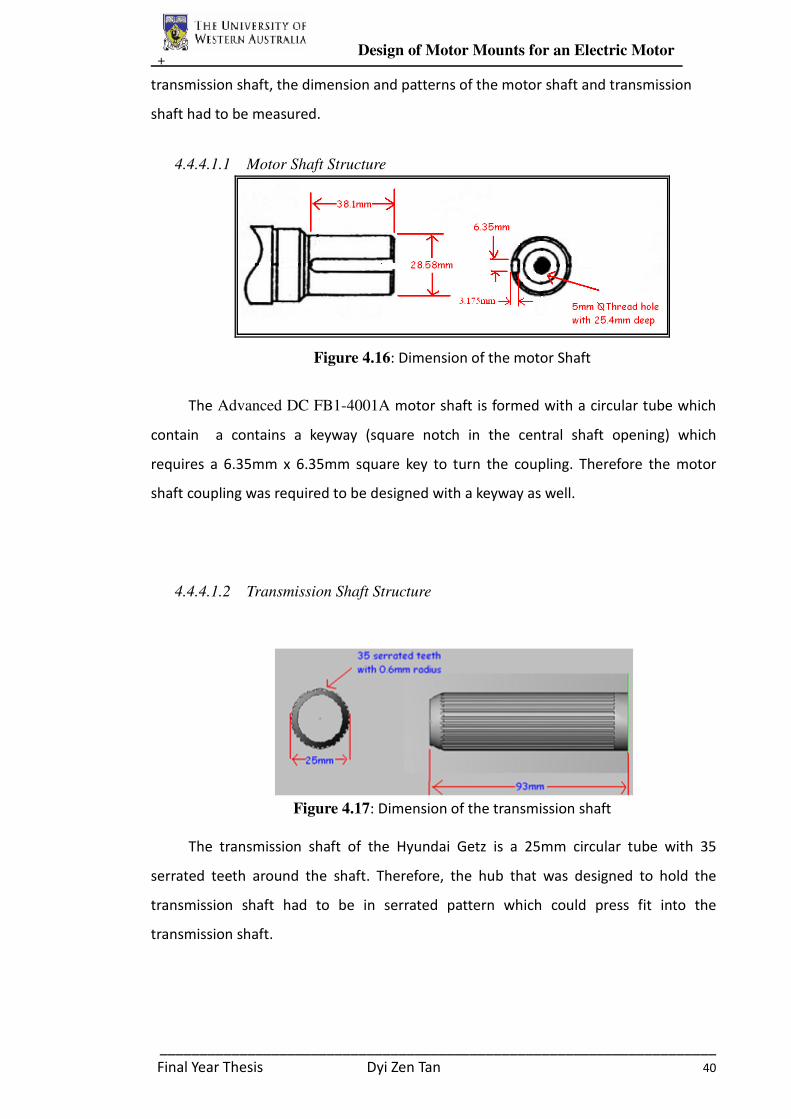
+ Design of Motor Mounts for an Electric Motor
______________________________________________________________________
Final Year Thesis Dyi Zen Tan 40
transmission shaft, the dimension and patterns of the motor shaft and transmission
shaft had to be measured.
4.4.4.1.1 Motor Shaft Structure
Figure 4.16: Dimension of the motor Shaft
The Advanced DC FB1-4001A motor shaft is formed with a circular tube which
contain a contains a keyway (square notch in the central shaft opening) which
requires a 6.35mm x 6.35mm square key to turn the coupling. Therefore the motor
shaft coupling was required to be designed with a keyway as well.
4.4.4.1.2 Transmission Shaft Structure
Figure 4.17: Dimension of the transmission shaft
The transmission shaft of the Hyundai Getz is a 25mm circular tube with 35
serrated teeth around the shaft. Therefore, the hub that was designed to hold the
transmission shaft had to be in serrated pattern which could press fit into the
transmission shaft.
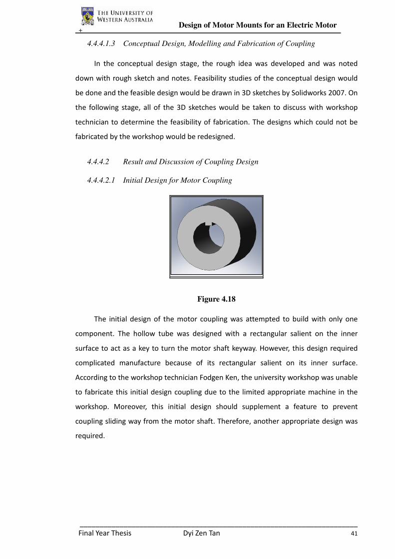
+ Design of Motor Mounts for an Electric Motor
______________________________________________________________________
Final Year Thesis Dyi Zen Tan 41
4.4.4.1.3 Conceptual Design, Modelling and Fabrication of Coupling
In the conceptual design stage, the rough idea was developed and was noted
down with rough sketch and notes. Feasibility studies of the conceptual design would
be done and the feasible design would be drawn in 3D sketches by Solidworks 2007. On
the following stage, all of the 3D sketches would be taken to discuss with workshop
technician to determine the feasibility of fabrication. The designs which could not be
fabricated by the workshop would be redesigned.
4.4.4.2 Result and Discussion of Coupling Design
4.4.4.2.1 Initial Design for Motor Coupling
Figure 4.18
The initial design of the motor coupling was attempted to build with only one
component. The hollow tube was designed with a rectangular salient on the inner
surface to act as a key to turn the motor shaft keyway. However, this design required
complicated manufacture because of its rectangular salient on its inner surface.
According to the workshop technician Fodgen Ken, the university workshop was unable
to fabricate this initial design coupling due to the limited appropriate machine in the
workshop. Moreover, this initial design should supplement a feature to prevent
coupling sliding way from the motor shaft. Therefore, another appropriate design was
required.
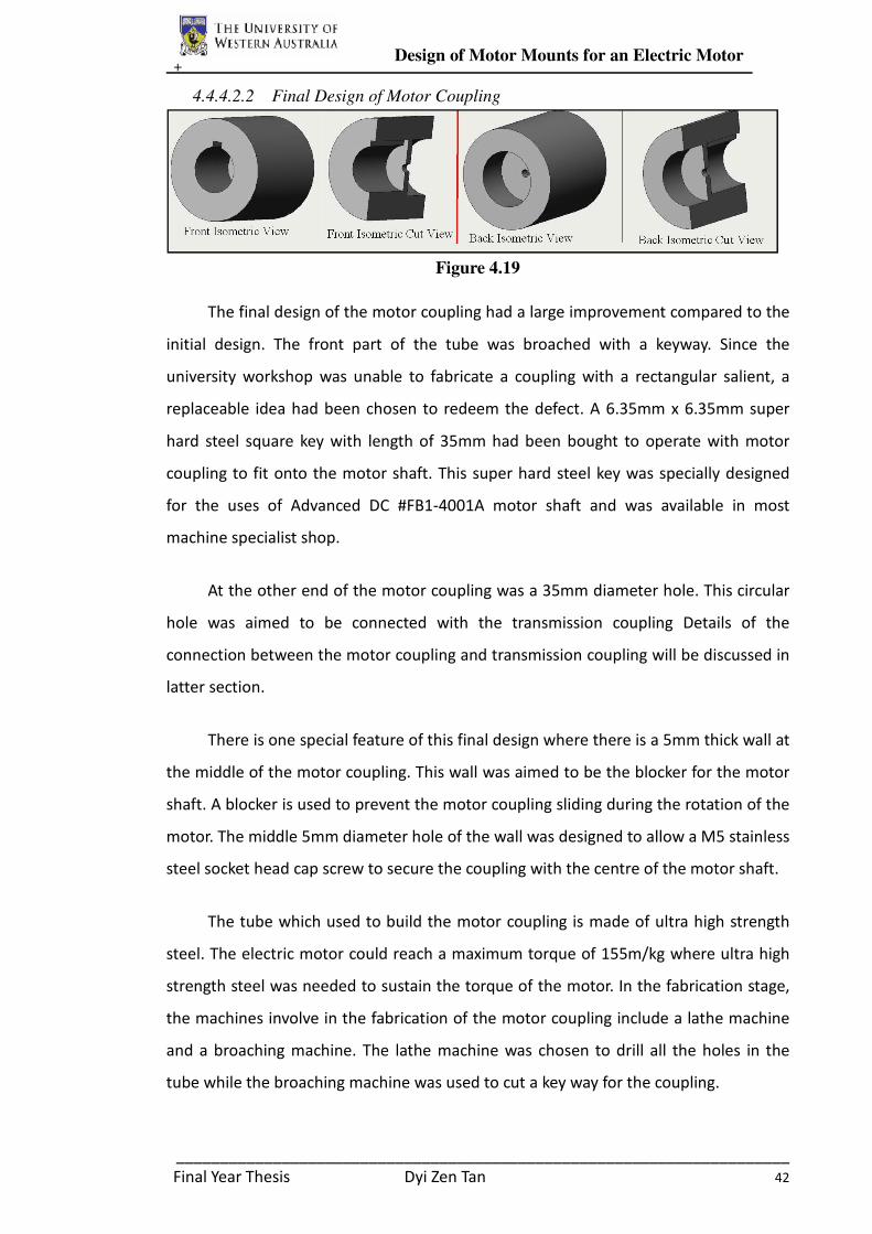
+ Design of Motor Mounts for an Electric Motor
______________________________________________________________________
Final Year Thesis Dyi Zen Tan 42
4.4.4.2.2 Final Design of Motor Coupling
Figure 4.19
The final design of the motor coupling had a large improvement compared to the
initial design. The front part of the tube was broached with a keyway. Since the
university workshop was unable to fabricate a coupling with a rectangular salient, a
replaceable idea had been chosen to redeem the defect. A 6.35mm x 6.35mm super
hard steel square key with length of 35mm had been bought to operate with motor
coupling to fit onto the motor shaft. This super hard steel key was specially designed
for the uses of Advanced DC #FB1-4001A motor shaft and was available in most
machine specialist shop.
At the other end of the motor coupling was a 35mm diameter hole. This circular
hole was aimed to be connected with the transmission coupling Details of the
connection between the motor coupling and transmission coupling will be discussed in
latter section.
There is one special feature of this final design where there is a 5mm thick wall at
the middle of the motor coupling. This wall was aimed to be the blocker for the motor
shaft. A blocker is used to prevent the motor coupling sliding during the rotation of the
motor. The middle 5mm diameter hole of the wall was designed to allow a M5 stainless
steel socket head cap screw to secure the coupling with the centre of the motor shaft.
The tube which used to build the motor coupling is made of ultra high strength
steel. The electric motor could reach a maximum torque of 155m/kg where ultra high
strength steel was needed to sustain the torque of the motor. In the fabrication stage,
the machines involve in the fabrication of the motor coupling include a lathe machine
and a broaching machine. The lathe machine was chosen to drill all the holes in the
tube while the broaching machine was used to cut a key way for the coupling.
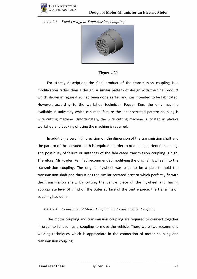
+ Design of Motor Mounts for an Electric Motor
______________________________________________________________________
Final Year Thesis Dyi Zen Tan 43
4.4.4.2.3 Final Design of Transmission Coupling
Figure 4.20
For strictly description, the final product of the transmission coupling is a
modification rather than a design. A similar pattern of design with the final product
which shown in Figure 4.20 had been done earlier and was intended to be fabricated.
However, according to the workshop technician Fogden Ken, the only machine
available in university which can manufacture the inner serrated pattern coupling is
wire cutting machine. Unfortunately, the wire cutting machine is located in physics
workshop and booking of using the machine is required.
In addition, a very high precision on the dimension of the transmission shaft and
the pattern of the serrated teeth is required in order to machine a perfect fit coupling.
The possibility of failure or unfitness of the fabricated transmission coupling is high.
Therefore, Mr Fogden Ken had recommended modifying the original flywheel into the
transmission coupling. The original flywheel was used to be a part to hold the
transmission shaft and thus it has the similar serrated pattern which perfectly fit with
the transmission shaft. By cutting the centre piece of the flywheel and having
appropriate level of grind on the outer surface of the centre piece, the transmission
coupling had done.
4.4.4.2.4 Connection of Motor Coupling and Transmission Coupling
The motor coupling and transmission coupling are required to connect together
in order to function as a coupling to move the vehicle. There were two recommend
welding techniques which is appropriate in the connection of motor coupling and
transmission coupling:

+ Design of Motor Mounts for an Electric Motor
______________________________________________________________________
Final Year Thesis Dyi Zen Tan 44
� Vacuum Brazing
Vacuum brazing is a materials joining technique that offers significant advantages:
extremely clean, superior, flux-free braze joints of high integrity and strength
(Wikipedia, 2008). This joining method is preferable as it provides a higher strength of
joint compared with the normal welding techniques. With vacuum brazing, all the
contact area of between the motor coupling and transmission coupling will be welded,
as shown in Figure 4.21. Therefore, both couplings were taken to physic workshop to
be vacuum brazed. Unfortunately, the vacuum brazing technique had failed to connect
the connection of those couplings. After an evaluation of the failure with Mr Fogden
Ken, the connection failure of vacuum brazing might be caused by the different
material of motor coupling and transmission coupling. The motor coupling is made of
ultra strength steel but the transmission coupling might be made of some kind of alloy.
The different melting temperature of two different materials might results a
connection failure with vacuum brazing technique.
Figure 4.21 : Welded Area of Vacuum Brazing
� MIG welding
MIG welding is a less preferable technique due to its lower strength of joint
compared to vacuum brazing. MIG welding technique would only weld on the contact
edge of the connection between motor coupling and transmission coupling, which is
shown in Figure 4.22. Although the MIG welding technique has a lower strength of
joint, the welding joint is capable to sustain the maximum torque of the motor, which
had been proven by the stress analysis which done by ANSYS Workbench. As a result,
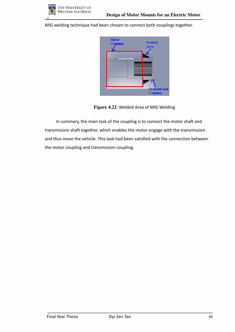
+ Design of Motor Mounts for an Electric Motor
______________________________________________________________________
Final Year Thesis Dyi Zen Tan 45
MIG welding technique had been chosen to connect both couplings together.
Figure 4.22: Welded Area of MIG Welding
In summary, the main task of the coupling is to connect the motor shaft and
transmission shaft together, which enables the motor engage with the transmission
and thus move the vehicle. This task had been satisfied with the connection between
the motor coupling and transmission coupling.
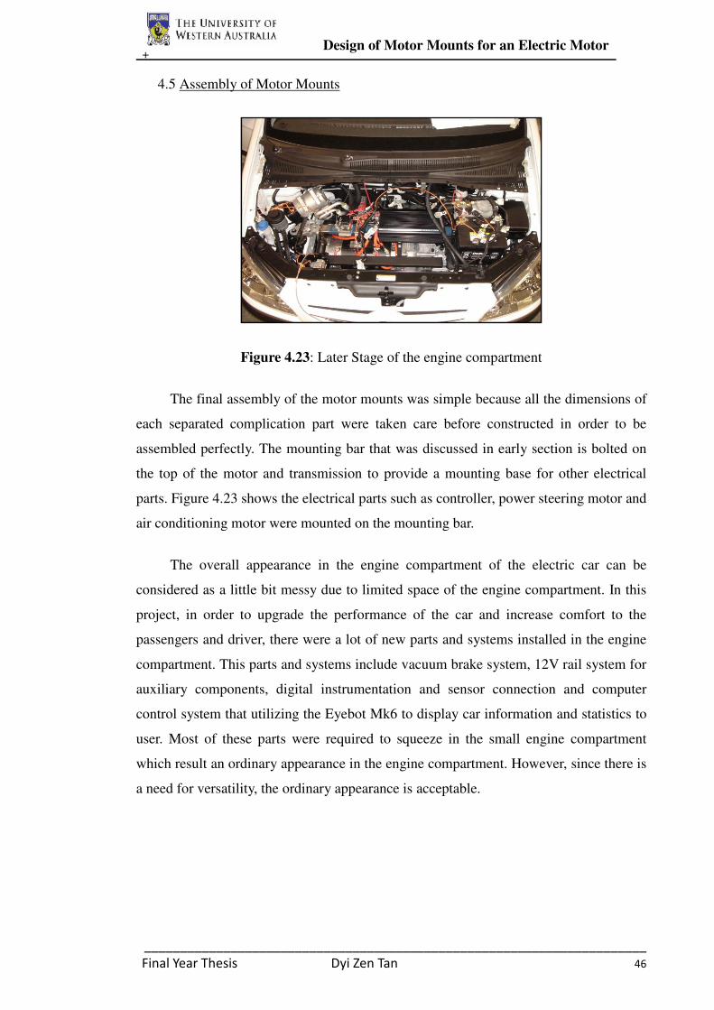
+ Design of Motor Mounts for an Electric Motor
______________________________________________________________________
Final Year Thesis Dyi Zen Tan 46
4.5 Assembly of Motor Mounts
Figure 4.23: Later Stage of the engine compartment
The final assembly of the motor mounts was simple because all the dimensions of
each separated complication part were taken care before constructed in order to be
assembled perfectly. The mounting bar that was discussed in early section is bolted on
the top of the motor and transmission to provide a mounting base for other electrical
parts. Figure 4.23 shows the electrical parts such as controller, power steering motor and
air conditioning motor were mounted on the mounting bar.
The overall appearance in the engine compartment of the electric car can be
considered as a little bit messy due to limited space of the engine compartment. In this
project, in order to upgrade the performance of the car and increase comfort to the
passengers and driver, there were a lot of new parts and systems installed in the engine
compartment. This parts and systems include vacuum brake system, 12V rail system for
auxiliary components, digital instrumentation and sensor connection and computer
control system that utilizing the Eyebot Mk6 to display car information and statistics to
user. Most of these parts were required to squeeze in the small engine compartment
which result an ordinary appearance in the engine compartment. However, since there is
a need for versatility, the ordinary appearance is acceptable.

+ Performance Evaluation
______________________________________________________________________
Final Year Thesis Dyi Zen Tan 47
5. Performance Evaluation
The main tasks of the motor mounts design was to provide a support to attach the
electric motor with the transmission in the engine compartment, transfer all the motor
vibration to the engine mount rubbers and provide a mounting base for other electrical
parts. In order to ensure these tasks were fully satisfied by the motor mounts design,
some tests had been done.
The first test was done when the electric car was 90% constructed. Although the
electric car was not fully completed, most of the important parts and system which are
required to run the vehicle had been installed. Parts and components which had not been
installed at that stage include dashboard, air conditioner systems and other parts which
will not affect the performance of the car. The main objective of this first test is to
ensure the motor were attached securely with the transmission.
Firstly, the motor was first run in different speed in the condition when the front
wheel of the car was lifted up by jack. This test was done to ensure all the motor mounts
parts and couplings are tough enough to run in low load condition. As what had been
expected, the front wheels of the car rotate smoothly in all speed and in different gear
shifts conditions, include the reverse gear mode. Besides, an observation of the
vibration from the motor and transmission had been done throughout the test. By
observation, the electric motor and transmission seemed to operate without any
vibration. However, a second road test had to be done to observe the vibration condition
of the motor running on road and to ensure the motor mounts and couplings are tough
enough to sustain the rotation of the motor.
The second test was a practical road test which was done within the university
area. Since the car had not been registered as a licensed road vehicle, the practical road
test could only be done in a moderate speed driving within the university area. The test
was started with only a driver driving along particular route within university area. A
passenger will be added each time when the car was finish tested, until a total of four
passengers and a driver were sat in the electric car. In the stage where the electric car
was full of passenger, the driving condition of the car was still smoothly. According to
all the passengers and drivers of the electric car, the car was powerful but still very quite.
The only problem of the electric car is too quite until the pedestrians did not notice a car
+ Conclusion & Recommendations of Future Project
______________________________________________________________________
Final Year Thesis Dyi Zen Tan 48
was coming towards them, which leads to a safety problem.
Since the electric car had not been licensed as a qualified road vehicle, the car
could not be tested on public highway with freeway speed. However, more different
tests were purposed to be done when the electric car had registered as a licensed road
vehicle.
6. Conclusion
Overall the design and construction of the motor mounts was a success. Some
simple tests had proved that the design was satisfied to engage the electric motor with
the transmission and isolate the vehicle structure from motor vibration. However, there
is still much room for improvement and adjustment of the motor mounts design and
construction. The completed electric car is planned to register as a licensed road vehicle
and it is aimed to launch at the end of 2008. Following the electric Getz project, the
REV team has planned to build a performance electric car by converting a Lotus Elise
into a performance electric car. All of the experience gained from Getz project can be
used as a valuable experience and guide for building the performance electric car later.
7. Recommendations of Future Project
The successful completion of this project had provided a reliable and steady
foundation for the development of UWA Renewable Energy Vehicle. Although the
Hyundai Getz Project had achieved a huge success, there is much room for
improvement of the motor mounts design for the performance electric car project.
Firstly, the connection between the motor coupling and the transmission coupling
could be strengthened by adding keys or screws for further securement.
Secondly, a longer size of transmission coupling should be designed to lock the
transmission shaft. The more contact area of transmission coupling lock to the
transmission shaft, the less abrasion of the serrated teeth of transmission shaft and thus
increase the coupling and shaft life.
Finally, a professional vibration analysis of the motor and transmission should be
performed to understand how well the motor mounts transfer the vibration to the mount
rubber and how efficient the vibration been interfered.
+ References
______________________________________________________________________
Final Year Thesis Dyi Zen Tan 49
8. References
Andersen, S.O, Atkinsen, W, Baker, J.A., Oulouhojian, S., Phillips, J.E., 2003, Technical
Options for Motor Vehicle Air Conditioning Systems, Society of Automotive Engineers.
Baker, K. 2008, Keeping Parts Connected With an Engine Mount, Street Directory.
Available from:
<http://www.streetdirectory.com/travel_guide/51802/car_parts/keeping_parts_connected
_with_an_engine_mount.html> [24 March 2008].
Brown, M & Prange, S 1993, Convert It, Quality Book Inc.
Brazing 2008, Wikipedia. Available from: < http://en.wikipedia.org/wiki/Brazing> [17
June 2008].
Chimera -- India's first plug-in hybrid car 2008, CyberMedia India Online Ltd.
Available from:
<http://www.ciol.com/Semicon/Product-Watch/News-Reports/Chimera----Indias-first-pl
ug-in-hybrid-car/13608107032/0/> [ 15 October 2008].
Cincurak, D. 2008, New Vehicle Construction, National Fire & Rescue Megazine.
Available from: < www.nfrmag.com/assets/pdf/2vehicleconstruction.ppt> [20 March
2008].
Department of Planning and Infrastructure, 2007, Minimum Requirements for Individual
Custom Built Vehicles, Perth.
Electric Car 2008, Wikipedia. Available from:
<http://en.wikipedia.org/wiki/Electric_car> [ 17 June 2008].
Electric Car Conversion Kit (For Beginners), Electric-Cars-Are-For-Girls. Available
from: < http://www.electric-cars-are-for-girls.com/electric-car-conversion-kit.html> [21
April 2008].
Electro Automotive 2008, Adaptors, Electro Automotive. Available from:
<http://www.electroauto.com/catalog/adaptors.shtml> [23 April 2008].
EVParts 2007, Motor,Advanced DC#FB1-4001, 9.1”, single shaft, Electric Vehicles,
+ References
______________________________________________________________________
Final Year Thesis Dyi Zen Tan 50
Parts and Accessories. Available from: <http://www.evparts.com/prod-MT2119.htm>
[15 May 2008].
Fuel Cell Vehicles 2008, Fuel Economy. Available from:
<http://www.fueleconomy.gov/feg/fuelcell.shtml> [15 August 2008].
Gribben, C 2001, Build an EV, The Electric Vehicle Association of Greater Washington
DC. Available from: <http://www.evadc.org/build_components.html> [28 March 2008].
Hartment, M. 2008, Electric Car Project Nears Completion, Brigham Young University
Newsnet. Available from: <http://newsnet.byu.edu/story.cfm/69926> [24 October 2008]
Hodkinson, R. & Fenton, J. 2001, Lightweight Electric/Hybrid Vehicle Design, Reed
Educational and Professional Publishing. Warrendale.
Hybrid Vehicles 2008, Wikipedia. Available from:
<http://en.wikipedia.org/wiki/Hybrid_car> [ 17 June 2008].
Mathew Rohan 2008, Welcome to the REV Project, The Renewable Energy Vehicle
Project. Available from: <http://www.therevproject.com>
Nice, K & Bryant, C 2008, How Clutches Work, How Stuff Works. Available from:
<http://auto.howstuffworks.com/clutch1.htm> [23 May 2008].
Solar Vehicle 2008, Wikipedia. Available from:
<http://en.wikipedia.org/wiki/Solar_vehicle> [ 17 June 2008].
Solar Vehicle Project: Centaurus 2008, University of Minnesota. Available from:
<http://www.svp.umn.edu/currentcar.html> [17 October 2008].
The Rotary Table 2004, Virtual Machine Shop. Available from:
<http://www.jjjtrain.com/vms/mill_rotary/mill_rotary_01.html> [27 June 2008].
Trev (two-seater renewable energy vehicle) 2008, The University of South Australia.
Available from: <http://www.unisa.edu.au/solarcar/trev/> [15 October 2008].
Vehicle Safety Standards Branch, 2008, The Code of Practice 2008for The Major Body
Modifications to Light Vehicles,Australia.

+ References
______________________________________________________________________
Final Year Thesis Dyi Zen Tan 51
Whitener, B. 1981, The Electric Car Book, Love Street Books, Louisville.
Wiki 2008, Electric Vehicle Conversion, Wikipedia. Available from:
<http://en.wikibooks.org/wiki/Electric_vehicle_conversion > [17 April 2008].

+ Appendix
______________________________________________________________________
Final Year Thesis Dyi Zen Tan 52
9. Appendix
9.1 Appendix A: Dimension of Advanced DC #FB1-4001, 9.1", single shaft

+ Appendix
______________________________________________________________________
Final Year Thesis Dyi Zen Tan 53
9.2 Appendix B : Torque Curve of Advanced DC #FB1-4001, 9.1", single shaft

+ Appendix
______________________________________________________________________
Final Year Thesis Dyi Zen Tan 54
9.3 Appendix C: Dimension of Transmission Coupling

+ Appendix
______________________________________________________________________
Final Year Thesis Dyi Zen Tan 55
9.4 Appendix D: Dimension of Motor Coupling

+ Appendix
______________________________________________________________________
Final Year Thesis Dyi Zen Tan 56
9.5 Appendix E: Material Properties of Aluminium Alloy 5083 Series