design and construction of highway pavement joint … material selection repair materials for...
TRANSCRIPT
Design and Construction of
Highway Pavement Joint Systems
Troubleshooting Joint Design
and Construction Issues
Mark B. Snyder, Ph.D., P.E.
Engineering Consultant to the
American Concrete Pavement Association
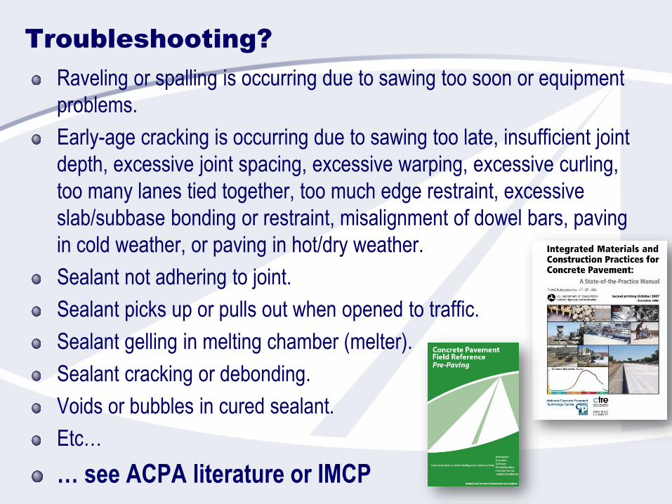
Troubleshooting?
Raveling or spalling is occurring due to sawing too soon or equipment
problems.
Early-age cracking is occurring due to sawing too late, insufficient joint
depth, excessive joint spacing, excessive warping, excessive curling,
too many lanes tied together, too much edge restraint, excessive
slab/subbase bonding or restraint, misalignment of dowel bars, paving
in cold weather, or paving in hot/dry weather.
Sealant not adhering to joint.
Sealant picks up or pulls out when opened to traffic.
Sealant gelling in melting chamber (melter).
Sealant cracking or debonding.
Voids or bubbles in cured sealant.
Etc…
… see ACPA literature or IMCP

Pavement Preservation
Philosophy
Keeping good roads in good condition!

M&R Types vs. Condition/Time

Benefits of Pavement
Preservation
Higher customer satisfaction
Improved pavement condition
Cost savings
Increased safety
Reduced environmental impact
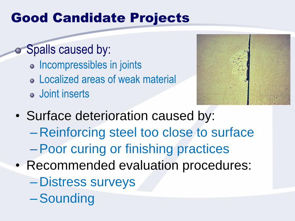
Good Candidate Projects
Spalls caused by:Incompressibles in joints
Localized areas of weak material
Joint inserts
• Surface deterioration caused by:
–Reinforcing steel too close to surface
–Poor curing or finishing practices
• Recommended evaluation procedures:
–Distress surveys
–Sounding
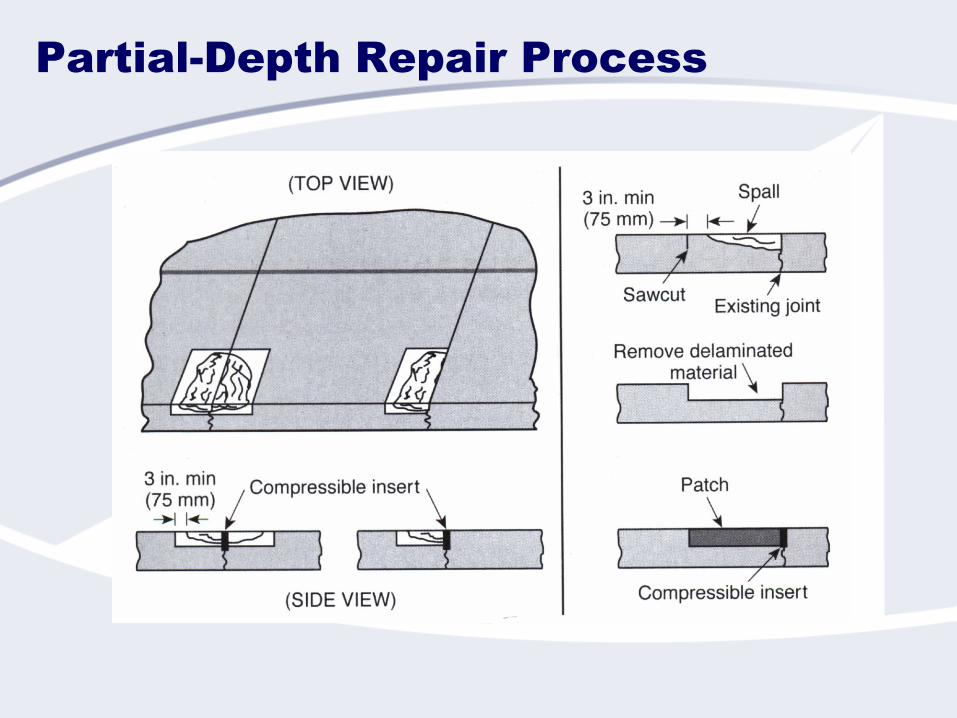
Partial-Depth Repair Process

Sizing of Repair
Greater than 3 inches beyond spall
Combine spalls if closer than 24 inches
Cementitious:
4 inch x 10 inch
2 inch depth
Proprietary:
Refer to manufacturer’s
instructions
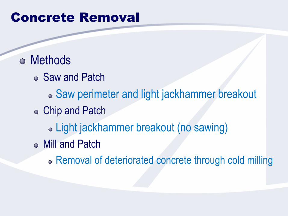
Concrete Removal
Methods
Saw and Patch
Saw perimeter and light jackhammer breakout
Chip and Patch
Light jackhammer breakout (no sawing)
Mill and Patch
Removal of deteriorated concrete through cold milling
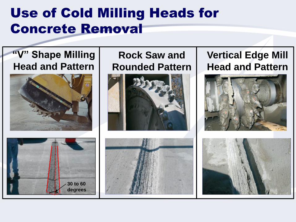
Use of Cold Milling Heads for
Concrete Removal
30 to 60
degrees
“V” Shape Milling
Head and PatternRock Saw and
Rounded Pattern
Vertical Edge Mill
Head and Pattern

Material Selection Factors
Allowable lane closure time
Ambient temperature
Material and placement cost
Material properties (shrinkage, CTE, bond strength)
Compatibility between repair material and existing pavement
Size and depth of repair
Performance capabilities
Repair Material Selection
Repair materials for partial-depth repairs are generally classified
cementitious, polymeric, or bituminous
Concrete mixes along with a wide variety of rapid-setting and high-
early-strength proprietary materials have been developed
High-quality portland cement concrete is generally accepted
as the most appropriate material for the repair of existing
concrete pavements
Concrete mix requires use of small-sized, coarse aggregate,
usually less than 1/2 in.
Bonding Agent
Intended to enhance bond between repair material
and existing pavement.
Can reduce bond if not installed properly
Required for many cementitious repair materials.
Some agencies allow clean, SSD surface in lieu of
bonding agent
Manufacturer’s instructions should be consulted for
proprietary mixes
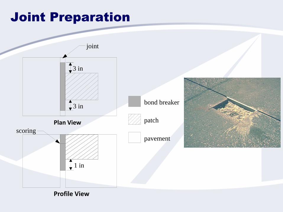
Joint Preparation
Plan View
Profile View
bond breaker
patch
pavement
3 in
3 in
scoring
1 in
joint
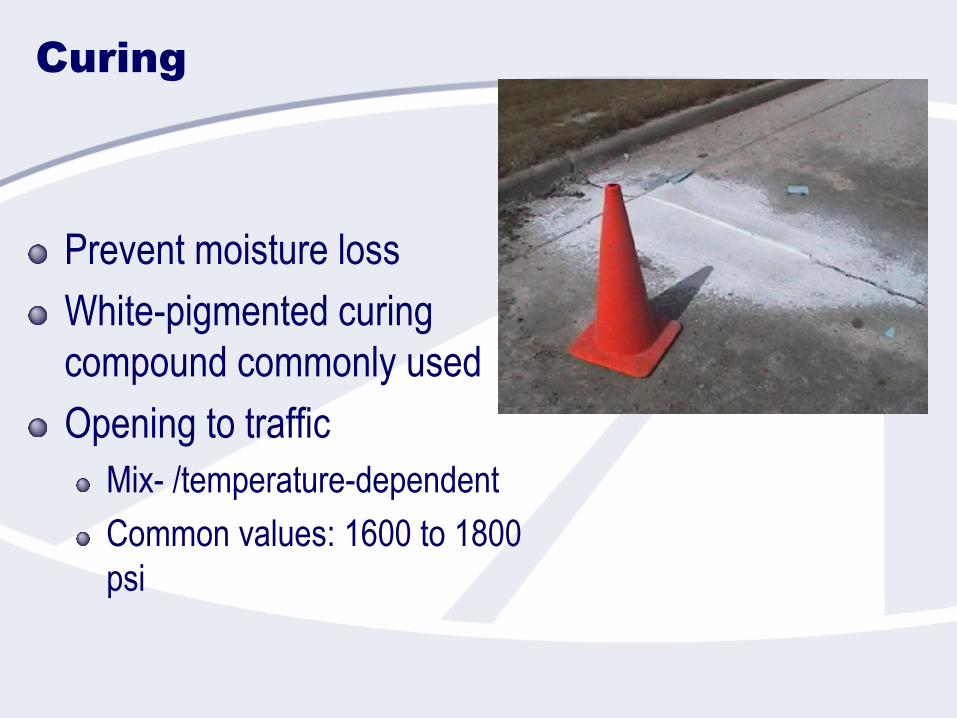
Curing
Prevent moisture loss
White-pigmented curing
compound commonly used
Opening to traffic
Mix- /temperature-dependent
Common values: 1600 to 1800
psi

Re-establish Joint/Crack
Type 1 and Type 2A joints have been successfully sawed.
Fresh concrete can also be tooled prior to sawing.
Joint reservoir must be wider than the crack under the
repair.
Tooling of the joint Sawing following tooling of the joint
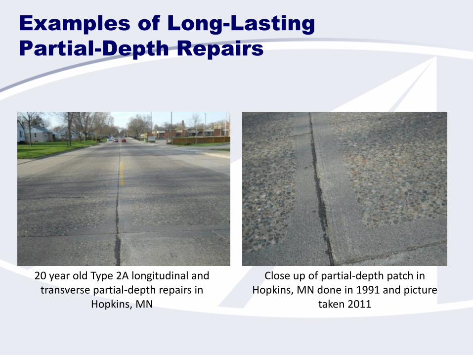
Examples of Long-Lasting
Partial-Depth Repairs
20 year old Type 2A longitudinal and transverse partial-depth repairs in
Hopkins, MN
Close up of partial-depth patch in Hopkins, MN done in 1991 and picture
taken 2011

Additional Resource
http://www.cptechcenter.org/technical-
library/documents/PDR_guide_Apr2012.pdf
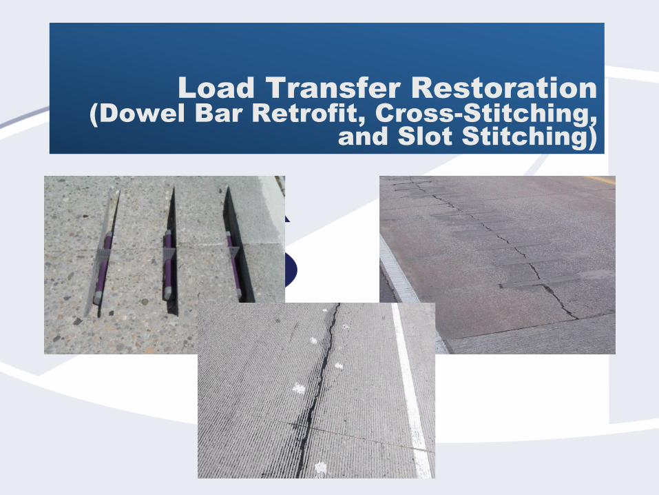
Load Transfer Restoration
(Dowel Bar Retrofit, Cross-Stitching,
and Slot Stitching)
Typical Causes of
Poor Load Transfer
Absence of load transfer devices
Failed load transfer devices
Poor aggregate interlock
Poor pavement drainage
Erodible base
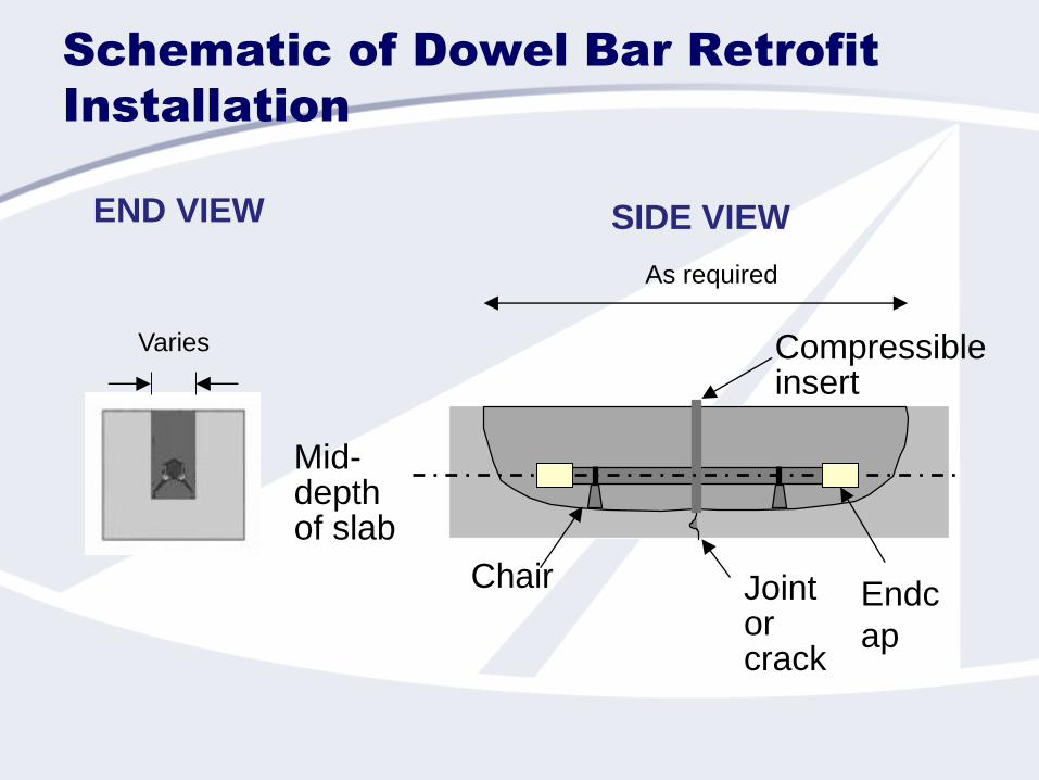
Schematic of Dowel Bar Retrofit
Installation
Varies
END VIEW
As required
SIDE VIEW
Chair Joint or crack
Mid-depthof slab
Compressible insert
Endc
ap
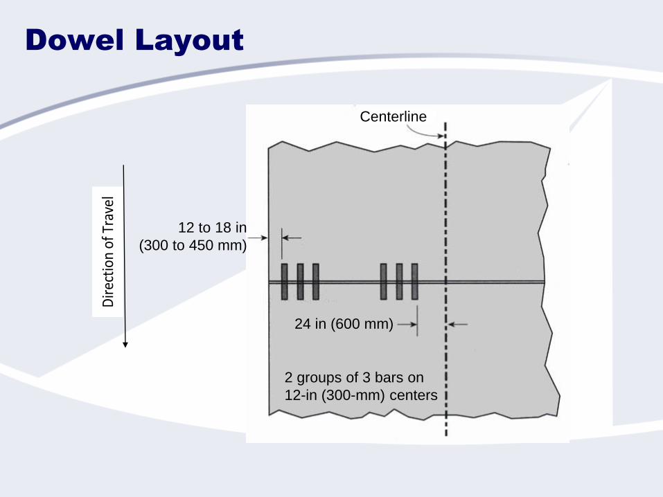
Dowel Layout
Centerline
12 to 18 in
(300 to 450 mm)
24 in (600 mm)
2 groups of 3 bars on
12-in (300-mm) centers
Dir
ecti
on o
f Tra
vel

Slot Creation
Slot Sawcuts
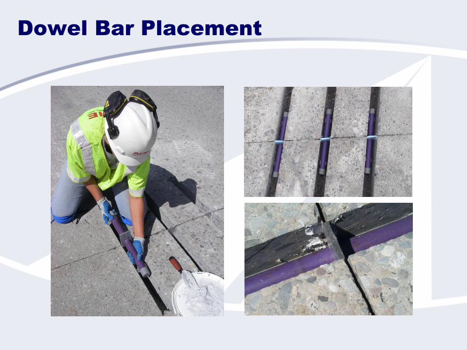
Dowel Bar Placement

Patching Material Placement
Consolidation and Finishing

Final Steps
Diamond grinding
Joint sealing

Cross Stitching
Definition
Used to strengthen nonworking longitudinal joints
and nonworking longitudinal cracks (in relatively
good condition)
Grouting of tiebars in holes drilled
across nonworking longitudinal joints
and cracks at an angle to the
pavement surface
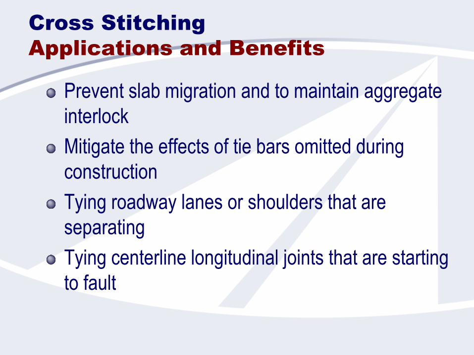
Cross Stitching
Applications and Benefits
Prevent slab migration and to maintain aggregate
interlock
Mitigate the effects of tie bars omitted during
construction
Tying roadway lanes or shoulders that are
separating
Tying centerline longitudinal joints that are starting
to fault
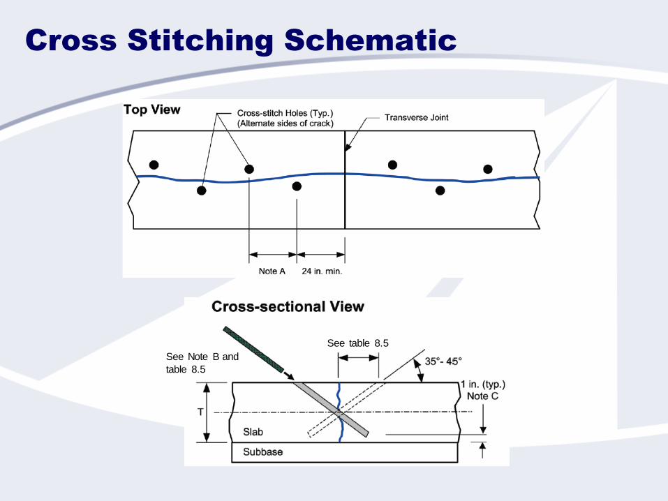
Cross Stitching Schematic
See table 8.5
See Note B and
table 8.5
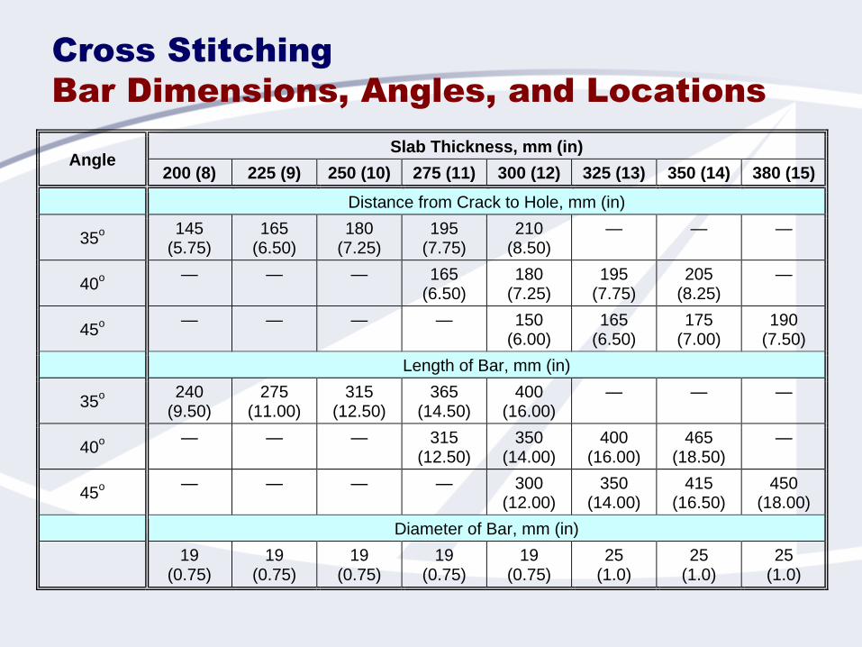
Cross Stitching
Bar Dimensions, Angles, and Locations
Angle Slab Thickness, mm (in)
200 (8) 225 (9) 250 (10) 275 (11) 300 (12) 325 (13) 350 (14) 380 (15)
Distance from Crack to Hole, mm (in)
35o
145 (5.75)
165 (6.50)
180 (7.25)
195 (7.75)
210 (8.50)
— — —
40o
— — — 165 (6.50)
180 (7.25)
195 (7.75)
205 (8.25)
—
45o
— — — — 150 (6.00)
165 (6.50)
175 (7.00)
190 (7.50)
Length of Bar, mm (in)
35o
240 (9.50)
275 (11.00)
315 (12.50)
365 (14.50)
400 (16.00)
— — —
40o
— — — 315 (12.50)
350 (14.00)
400 (16.00)
465 (18.50)
—
45o
— — — — 300 (12.00)
350 (14.00)
415 (16.50)
450 (18.00)
Diameter of Bar, mm (in)
19
(0.75) 19
(0.75) 19
(0.75) 19
(0.75) 19
(0.75) 25
(1.0) 25
(1.0) 25
(1.0)
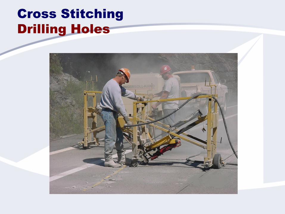
Cross Stitching
Drilling Holes
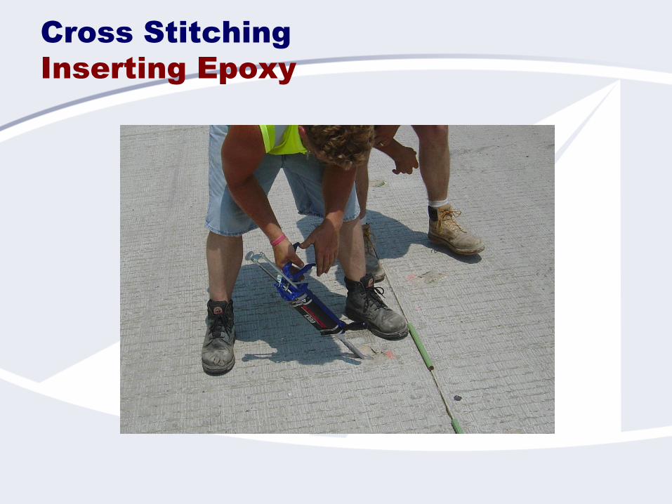
Cross Stitching
Inserting Epoxy

Cross Stitching
Bar Insertion
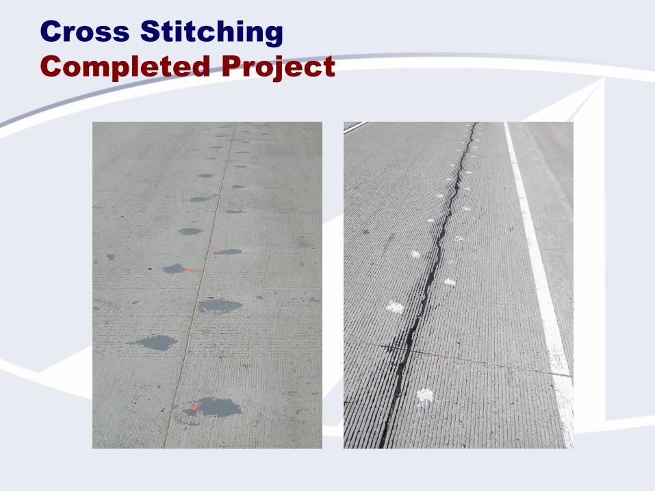
Cross Stitching
Completed Project
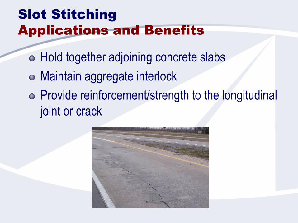
Slot Stitching
Applications and Benefits
Hold together adjoining concrete slabs
Maintain aggregate interlock
Provide reinforcement/strength to the longitudinal
joint or crack
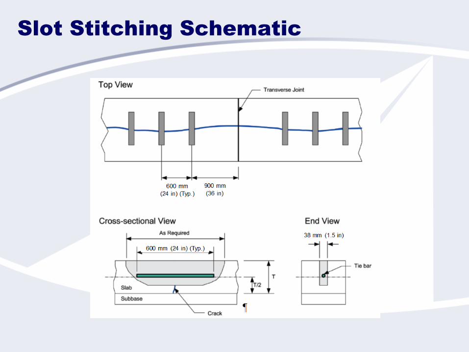
Slot Stitching Schematic
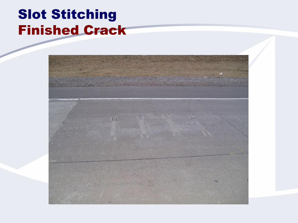
Slot Stitching
Finished Crack

Full-Depth Repairs
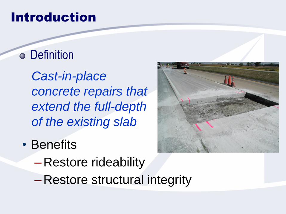
Cast-in-place
concrete repairs that
extend the full-depth
of the existing slab
Introduction
Definition
• Benefits
–Restore rideability
–Restore structural integrity
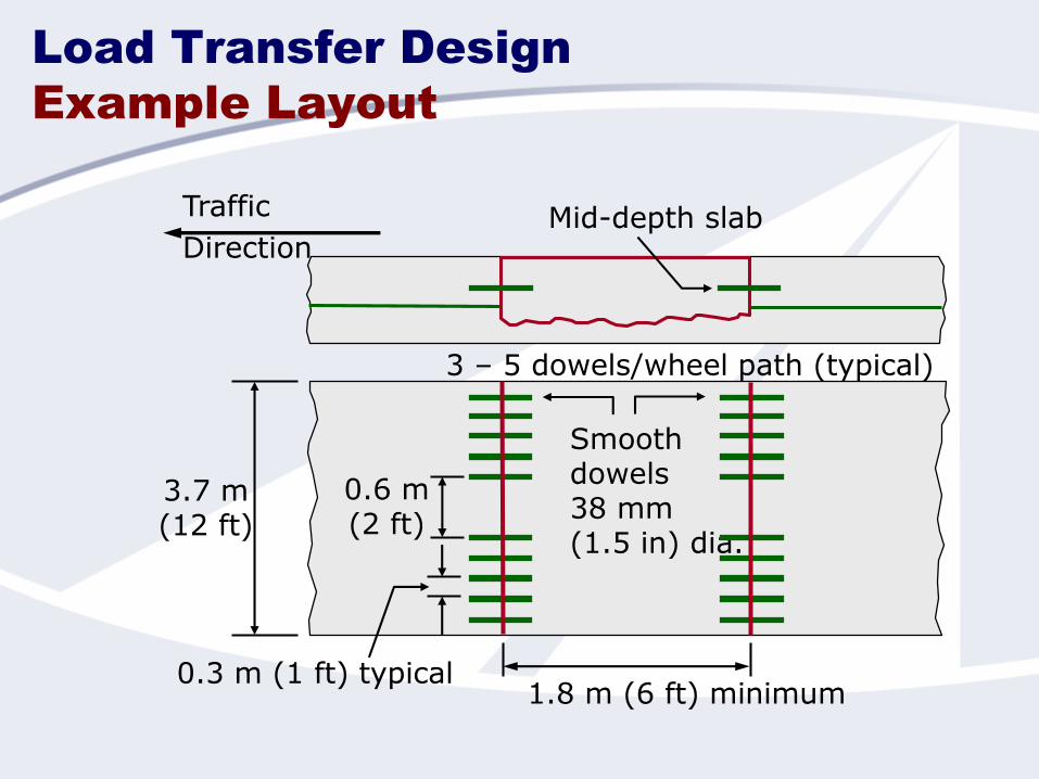
Load Transfer Design
Example Layout
Smoothdowels38 mm (1.5 in) dia.
3.7 m(12 ft)
0.6 m(2 ft)
0.3 m (1 ft) typical1.8 m (6 ft) minimum
Mid-depth slabTraffic
Direction
3 – 5 dowels/wheel path (typical)
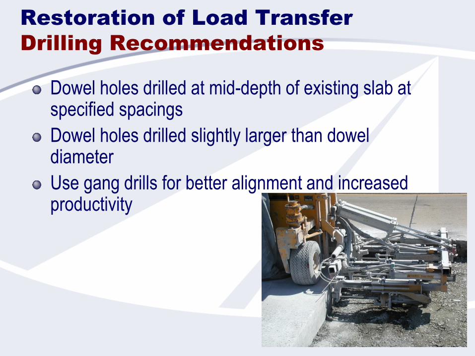
Restoration of Load Transfer
Drilling Recommendations
Dowel holes drilled at mid-depth of existing slab at specified spacings
Dowel holes drilled slightly larger than dowel diameter
Use gang drills for better alignment and increased productivity
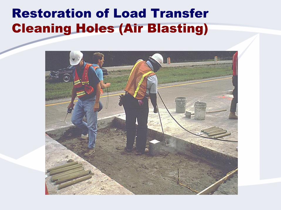
Restoration of Load Transfer
Cleaning Holes (Air Blasting)

Restoration of Load Transfer
Injecting Anchoring Material
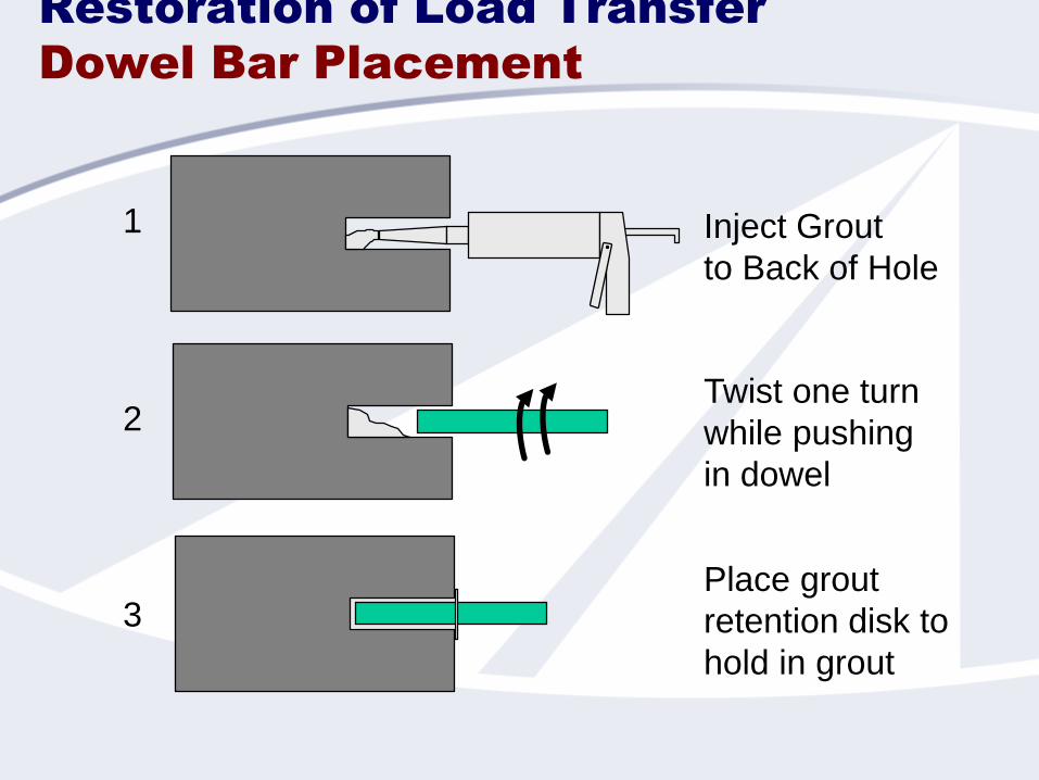
Restoration of Load Transfer
Dowel Bar Placement
3
2
1 Inject Grout
to Back of Hole
Twist one turn
while pushing
in dowel
Place grout
retention disk to
hold in grout

Subbase
Repair area
Anchoring materialGrout-retentiondisk (optional)
Hole dia. = d+a
Existing slab
a = 2 mm (1/8 in) for epoxy a = 6 mm (1/4 in) for cement grout
d = dowel diameter
Subgrade Soil
Restoration of Load Transfer
Schematic of Dowel Bar
Installation
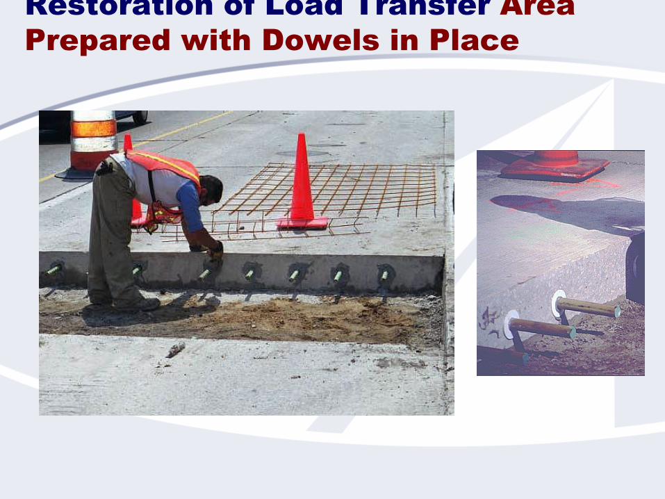
Restoration of Load Transfer Area
Prepared with Dowels in Place
Key Factors For Success (JCP)
Selection of proper candidate projects
Properly sized repairs
Good material removal practices
Properly prepared repair area
Effective restoration of load transfer
Selection of appropriate repair material
Proper material placement, finishing, and curing
Pavement Preservation
Source Material
http://www.cptechcenter.org/technical-library/documents/preservation_guide_2nd_ed_508_final.pdf
Precast Concrete Repairs

Precast Concrete Slabs
Prefabricated panels used for repair or
reconstruction of roadway pavements
Advantages:
Better quality concrete
Improved curing
Minimal weather impacts
Rapid opening
Prevent early-age construction failures
A number of systems are available

Jointed Precast Concrete Pavement
Systems (JPrCP)
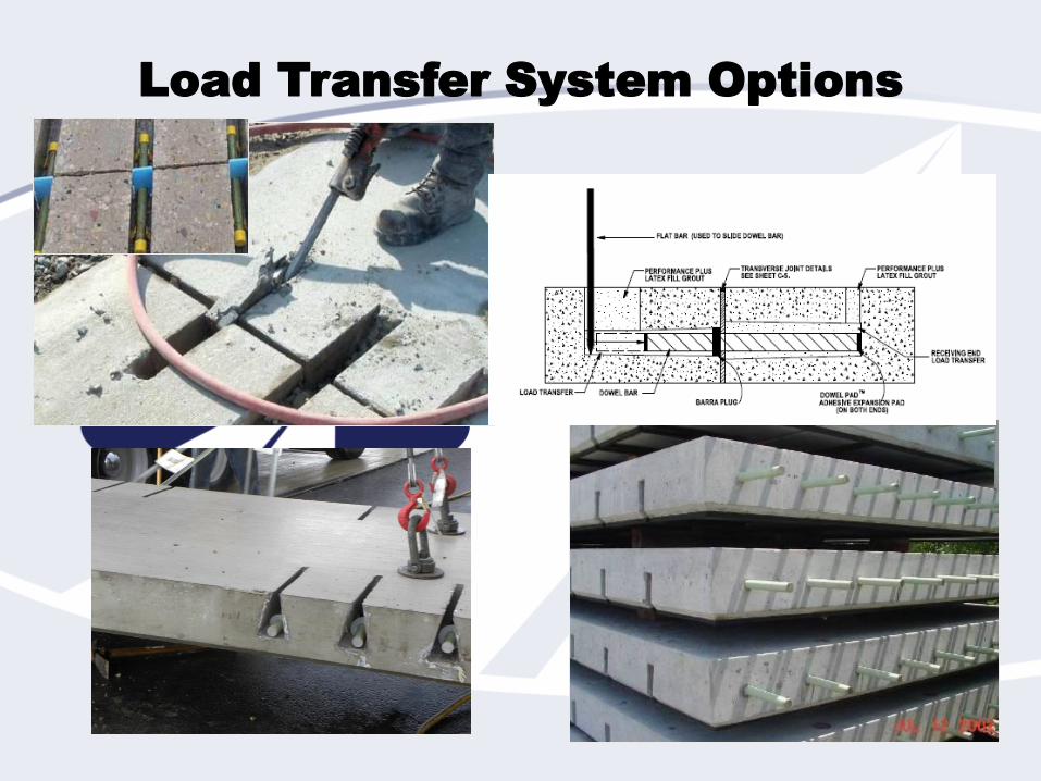
Load Transfer System Options
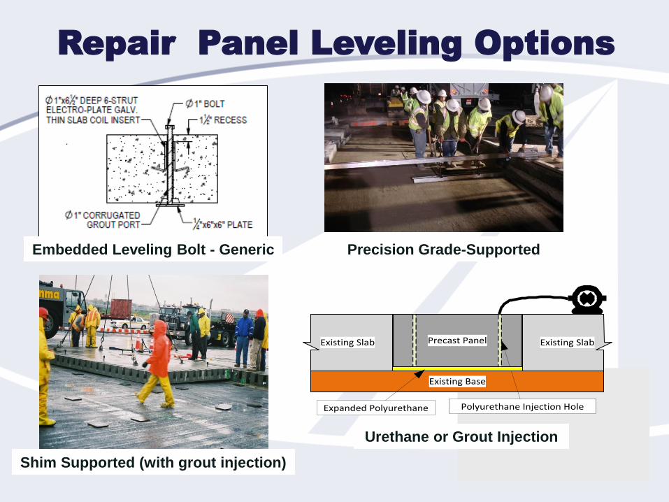
Repair Panel Leveling Options
Embedded Leveling Bolt - Generic Precision Grade-Supported
Shim Supported (with grout injection)
Existing Slab Existing Slab
Existing Base
Precast Panel
Polyurethane Injection HoleExpanded Polyurethane
Urethane or Grout Injection
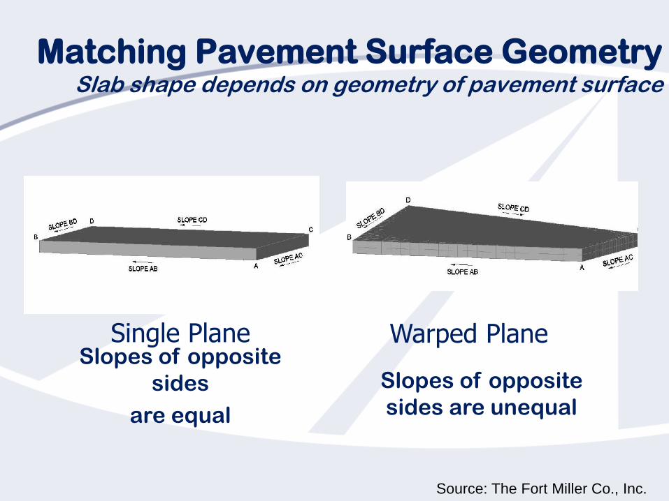
Matching Pavement Surface GeometrySlab shape depends on geometry of pavement surface
Warped PlaneSingle Plane Slopes of opposite
sides
are equal
Slopes of opposite
sides are unequal
Source: The Fort Miller Co., Inc.
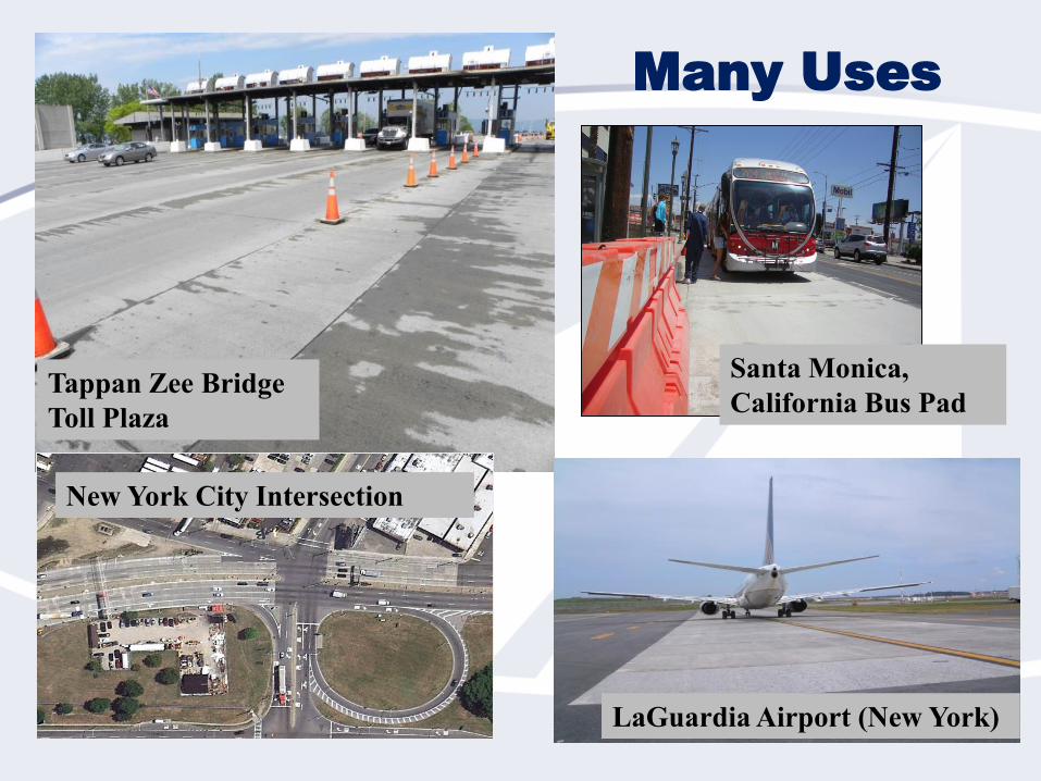
Many Uses
Tappan Zee Bridge
Toll Plaza
LaGuardia Airport (New York)
Santa Monica,
California Bus Pad
New York City Intersection
Acknowledgment
Much of the pavement preservation material
included in this presentation are excerpted from
the Pavement Preservation Workshop that was
developed by the National Concrete Pavement
Technology Center through Federal Highway
Administration funding.
Precast paving material is provided by the
National Precast Concrete Association and The
Fort Miller Company, Inc.