design and construction of grs integral bridges for
TRANSCRIPT
1 INTRODUCTION
A typical conventional bridge has a girder that is simple-supported by a pair of abutments via a pair of bearings (i.e., a fixed/pin and a movable/roller), while unreinforced approach fills are constructed re-tained by the abutments that have been constructed in advance. For these features of structural and con-struction, the following several problems often take place. Firstly, as the abutments are a cantilever struc-ture, with an increase in the abutment height and with a decrease in the bearing capacity of the supporting ground, the construction of the abutments supported by piles becomes increasingly more costly to keep small the displacements of the abutments caused by earth pressure and ground movements associated with the construction of approach fills. Secondly, 1) installation of bearings with arrangements preventing the dislodging of the girder by seismic loads; and 2) long-term maintenance preventing the corrosion of the bearings are also rather costly. Thirdly, the seismic stability of the cantilever-type abutments and un-reinforced backfill is basically rather low. Fourthly, a relatively large bumping may develop immediately back of the abutment gradually by self-weight and long-term traffic loads and suddenly by seismic loads enhanced by displacements of the abutment and deformation of the supporting ground.
To alleviate these problems due to the use of bearings with the conventional type bridges, integral bridges were developed and many have been constructed in the UK and the North America. This bridge type comprises a continuous girder that is structurally integrated to a pair of abutments without using bearings. However, as unreinforced approach fills are constructed after the construction of the abutments, many problems of the conventional bridge type remains unsolved. Besides, a new problem develops: i.e.,
Design and construction of GRS integral bridges for railways in Japan
Masayuki Koda,Hidetoshi Nishioka & Kenichi Kojima Railway Technical Research Institute(RTRI), Japan
Shinichi Tamai Japan Railway Construction Transport and Technology Agency (JRTT), Japan
Fumio Tatsuoka*
Tokyo University of Science ([email protected])
ABSTRACT: Geosynthetic-Reinforced Soil (GRS) integral bridge was developed and constructed for the first time in Japan. A pair of GRS retaining walls (RWs) are first constructed as the main component of a pair of abutments of a GRS integral bridge. After the deformation of supporting ground and fills has tak-en place sufficiently, a RC full-height rigid (FHR) facing is constructed by casting-in-place concrete on the wall face of each GRS RW wrapped-around with geogrid layers reinforcing the backfill in such that the facing is firmly integrated to the GRS RW. Finally, a continuous girder is constructed with both ends structurally integrated to the top ends of the pair of FHR facing. Due to very-high cost effectiveness with excellent performance against not only severe seismic loads but also long-term train loads requiring min-imized maintenance work, this technology has been well accepted by railway engineers. Potential prob-lems of residual forces in the RC structures due to annual thermal deformation and long-term concrete dry shrinkage of the girder and seismic loads become more serious with longer spans. Several technolo-gies were develop to alleviate these problems based on results of a series of cyclic loading tests per-formed on a full-scale partial model comprising a FHR facing with a buffer zone and part of approach block. To confirm the relevance of the structural design and construction method adopted, performance of a GRS integral bridge with a span of 60 m was observed in details from during construction and for several years after completion.
Keywords: geosynthetic-reinforced soil integral bridge, long-term behavior, railway, seismic behavior

the backfill is cyclically displaced laterally by annual thermal deformation of the girder, which results in both residual settlement of the backfill by active failure and development of high passive earth pressure (i.e., the dual ratcheting phenomenon; Tatsuoka et al., 2009, 2010, 2018). Results from a series of model tests showed that these problems can be alleviated by reinforcing the backfill with reinforcement layers connected to the back of the abutments (i.e., the full-height rigid (FHR) facings while maintaining the ad-vantages of the integral bridge. This new type bridge is called Geosynthetic-Reinforced Soil (GRS) inte-gral bridge (Fig. 1). Following the construction method of GRS RW with FHR facing (Tatsuoka et al., 1997), after the deformation of the supporting ground and the backfill associated with the construction of the reinforced backfill has taken place, FHR facings are constructed by casting-in-place concrete on the wall face wrapped-abound with geogrid layers reinforcing the backfill. By this staged-construction proce-dure and due to the fact that the FHR facing becomes a continuous beam supported by reinforcement lay-ers at many elevations (Tatsuoka 1992). Therefore, the internal forces and the lateral thrust forces and overturning moment at the base become very small compared with the abutments of the conventional type bridge. For this reason, pile foundations becomes unnecessary in usual cases. As the girder and FHR facings constitute a thin RC frame structure, the forces activated in the girder become much lower than those in the simple-supported girder of the conventional type bridge. Therefore, the girder and facings (i.e., abutments) of GRS integral bridge are much less massive than those of the conventional type bridge under otherwise the same conditions.
Firmly connected
3. FHR facing
4. Girder
1. Ground improvement
(when necessary)
2. GRS wall
Gravel
bags
The numbers 1 – 5 indicate the construction sequence.
5. Structural
integration
Figure 1. Structure of GRS integral bridge (the numbers denote the construction sequence).
Figure 2. Full-scale model of GRS integral bridge (Nagatani et al., 2009; Koda et al. 2013)
Figure 3. A general view of the model with arrangements for lateral loading tests (Koda et al., 2013).
To confirm the construction details of this new type bridge and the performance, a full-scale model of GRS integral bridge was constructed at the Railway Technical Research Institute for a period from the end of 2008 to the beginning of 2009 (Fig. 2). The behavior of the model was observed for two years and it was found that since post-construction residual deformations in the RC members and the approach blocks made of either cement-mixed gravelly soil or uncemented gravelly soil immediately behind the facings were very small. To validate high performance of GRS integral bridge when subjected to thermal effects and severe seismic loads, a series of lateral cyclic loading tests were performed on a full-scale model comprising a 14.75 m-long girder and 5.55 m-high facings with a width of 3 m in Feb. 2011 (Fig. 3; Koda et al., 2013). In one-side cyclic loading tests simulating thermal effects by a temperature change of 20o in centigrade for a girder length of 14.75 m, no significant increase took place in the earth pressure
on the back of the facing and the settlement of the backfill was negligible. These results show that, at least within the limit of the conditions in these tests, the thermal effects are negligible. In reversed lateral cyclic loading tests simulating seismic loading reaching L2 design seismic load (i.e., the highest seismic load that is likely to take place during a given life time in the future), when the lateral load equivalent to the inertia of the girder by L2 seismic load was fully applied to the girder, some noticeable effects were observed: i.e., the tensile force in the geogrid at some places reached its rupture strength, thin tensile cracks developed on the crest of the approach blocks and a horizontal tensile crack developed at the con-struction joint of the facing. However, the damage level is substantially below the level at which repair works become necessary, showing that the GRS integral bridge has a very high seismic stability.
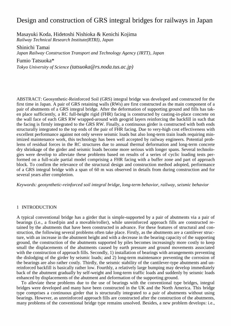
Figure 4. Full-scale partial model consisting of a FHR facing, a buffer zone and part of approach block of GRS in-tegral bridge arranged in a loading frame.
Potential effects of annual thermal deformation and long-term concrete dry shrinkage of the girder and seismic loads become more serious with longer GRS integral bridges. In particular, the effects on the buffer zone between the facing and the approach block of cement-mixed gravelly soil would be signifi-cant that should be carefully taken into account in the design of GRS integral brides with a span longer than about 20 m. In view of the above, a series of cyclic loading tests were performed on a full-scale par-tial model consisting of a FHR facing, a buffer zone and part of the approach block (Fig. 4). To confirm the relevance of the structural design adopted based on results of these model tests, the performance of a prototype GRS integral bridge with a 60 m-long span was observed from during construction and for sev-eral years after completion. This paper summarizes these experiences.
2 CYCLIC LOADING TESTS OF FULL-SCALE PARTIAL MODEL OF GRS INTEGRAL BRIDGE
Figure 4 shows a full-scale partial model of GRS RW arranged in a loading frame. The model is 1.0 m-
wide, 2.1 m-high and 5.05 m-long constructed under plane strain conditions in a steel soil container as-
sembled with reaction frames for loading. To reduce wall friction, composite panels smeared with a
grease layer were arranged on the inner faces of the soil container. The approach block consisted of 30
cm-thick layers of gravelly soil (M40) mixed with cement 3% in dry weight of gravel sandwiched with
geogrid layers. Each 30 cm-thick soil layer consisted of four 7.5 cm-thick sub-layers compacted to 95.5 %
of the maximum dry density by Modified Proctor. Unconfined compression tests were performed on
specimens of 20 cm in diameter and 40 cm-high of the cemented gravelly soil cured for a period of 56
days as in the full-scale model loading. The average unconfined compression strength was 7.1 MPa. The
design tensile rupture strength (Tk) of the geogrid was 101 kN/m. The vertical spacing between the ge-
ogrid layers was 30 cm, while the length was 4.6 m with longer ones and 3.0 m with shorter ones (Fig. 4).
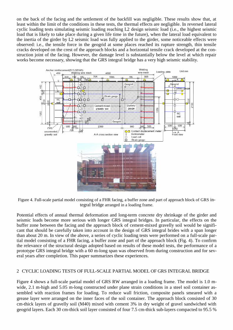
Fig. 5 shows the structure of the buffer zone between the FHR facing and the approach block. A welding
wire mesh framework (Fig. 5c) was used to form a temporary facing that should function until the con-
struction of a 2.1 m-high RC FHR facing by casting-in-place fresh concrete directly on the welding wire
mesh wrapped around with a geogrid sheet for a firm connection (Fig. 5b). The total tensile rupture
strength for all of the six geogrid layers is estimated to be about 650 kN, while the total fixing strength
between the FHR facing and the welding wire meshes is estimated to be about 250 kN with a 95% confi-
dence based on the previous experiment results. As the total strength of these two components may not be
sufficient when subjected to severe seismic loads simulated in the tests, six layers of four steel rods (D13,
L=350 mm) were anchored in welding wire meshes (Figs. 5a & 5b). Compacted unbound gravelly soil
was arranged in each 70 cm-long welding wire mesh framework and also in a free length of 30 cm be-
tween the tail end of the welding wire mesh and the front of the approach block to effectively absorb cy-
clic lateral deformation due to thermal changes in the girder length.
a) b) c)
Figure 5. a) Buffer zone between FHR facing and approach block of cement-mixed gravelly soil; b) front view of
the wall face before arranging a FHR facing; and c) top view of the welding wire mesh before placing gravelly soil.
A total vertical load of 500 kN, equivalent to average vertical pressure of 109 kPa, was applied to the crest of the buffer zone and the approach block by means of a set of center-hole hydraulic jacks arranged at the top of the vertical PC steel rods that connected five top 5 m-long and five bottom 7 m-long steel re-action beams (Fig. 4). 500 kN consisted of 161 kN by the weight of road bed and train load and 339 kN by the weight of overlying 3.2 m-high backfill. So, the lateral load applied in the model test is equivalent to the one applied to 1.8 m-thick bottom part of a 5.3 m-high wall. Without applying this vertical load, it is not possible to apply large lateral loads to the model without slipping at the bottom of the model. Ac-tive lateral loads in tension was applied by means of a pair of center-hole hydraulic jacks arranged at the end of PC rods connected to 1/4 and 3/4 heights of the FHR facing. Passive lateral load in compression was applied by means of a hydraulic jack to the central height of the FHR facing. As listed in Table 1, cases 1, 2 and 3 simulating lateral loading by thermal deformation and concrete drying shrinkage of the girder were performed. The number of loading cycles was 5 in case 1 and 15 in each of cases 2 and 3. Then, case 4 simulating seismic loading was performed. The methods of measuring several physical quantities are indicated in Fig. 4.
Table 1. Cyclic loading tests.
Test
case Action type
Assumed girder
span (m)
Maximum displacement (mm)
Active in tension Passive in compression
Case 1 Thermal action with
drying shrinkage of
concrete**
20 4 -1
Case 2 40 8 -2
Case 3 60 12 -3
Case 4 Seismic action - Load control* *: Same load as the passive load in case 1. **: Assumed thermal change= ± 25o; assumed drying shrinkage of concrete= 150 μ.

Fig. 6 shows the relationships between the lateral load (positive in tension) and the lateral displacement at the facing (positive in the active mode) in cases 1 through 4. The largest peak tensile load in cases 1, 2 and 3 simulating thermal effects was about 270 kN, which is much lower than the nominal tensile rupture load when all the geogrid strands are equally strained, equal to 624.3 kN/m = 2.4 kN/per strand (tensile load at design strain equal to 5 %) times the total number of geogrid strand. Besides, nearly the same rela-tion is traced by cyclic loading in each case. These results indicate insignificant damage to the geogrid in the buffer zone, if any, in these cases. In each case, the peak tensile load gradually decreases with cyclic loading. This result indicates that, with an increase in the number of loading cycle, the restraint of the welding wire mesh on the tensile deformation of the geogrid arranged in the buffer zone becomes weaker, which results in a gradual decrease in the average stiffness of the geogrid in the buffer zone.
a) b)
Figure 6. Relationships between lateral load and displacement of FHR facing, Cases 1, 2, 3 and 4: a) whole relation;
and b) enlarged relation in the active state..
In case 4 simulating seismic events, the maximum peak tensile equal to about 350 kN developed when the active facing displacement was about 25 mm. As this measured peak load (350 kN) is only about a half of the design load (624.3 kN), it seems that the strain in the geogrid strands was not uniform, there-fore, the failure of the whole geogrid layers was progressive even when nominally uniform load was ap-plied. By subsequent loading, the peak tensile load started decreasing associated with an increase in the active facing displacement. It seems that part of the geogrid exhibited tensile rupture as noticed by rup-ture sound. Yet, the geogrid in the buffer zone did not exhibit brittle tensile failure, but it maintained a re-sidual resistance of about 200 kN at least until the active facing displacement became about 60 mm.
Figure 7. Distributions of geogrid strains in cases 1, 2, 3 & 4.
Fig. 7 shows the distributions of tensile strains in the geogrid measured with electric-resistance gauges in
the buffer zone at the end of loading in each of cases 1, 2 and 3 and different displacements in case 4.
Despite that the measuring locations are not dense enough to know the details, it may be seen that the
strain is concentrated in the free zone between the tail end of welding wire mesh and the approach block
of cement-mixed gravelly soil. Obviously, the development of geogrid tensile stain is largely restrained
by the friction along the interface with a welding wire mesh framework, which has a stiffness larger by a
factor of more than 50, than the geogrid layer. It seems that, in the zone where a welding wire mesh and a
geogrid layer are overlapping, most of the tensile load applied to the FHR facing is resisted by the weld-
ing wire mesh. The geogrid strain in the approach block is very small, kept nearly zero at a depth of 200
mm. These results indicate that most of the tensile deformation of the geogrid takes place a 30 cm-wide
free zone and some in a narrow zone with a width of about 10 cm at largest that comprises a tail end zone
of the welding wire mesh zone and a front zone of the approach block. By such an approximation that the
geogrid is strained uniformly in a 40 cm-long zone, the lateral displacement limit for no damage to the
geogrid becomes 12 mm when based on the largest tensile strain equal to 3 % in case 3, while the dis-
placement at which the maximum tensile resistance is exhibited becomes 20 mm when conservatively
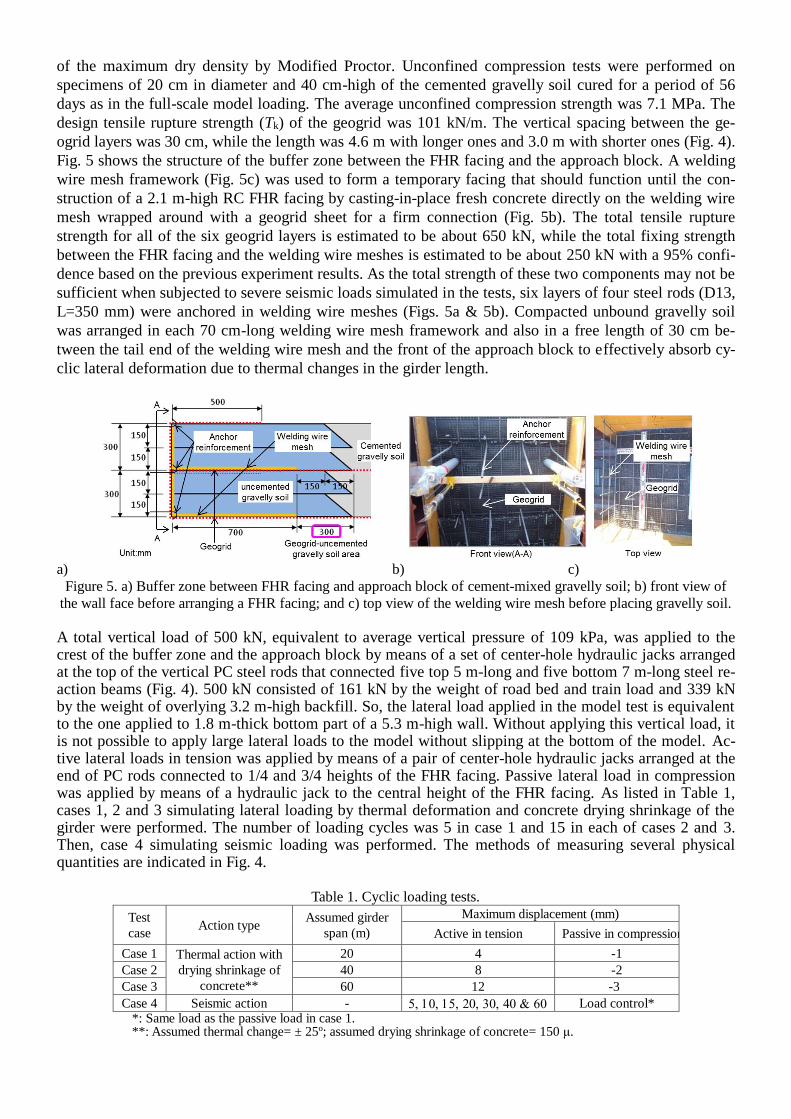
based on the test result in case 4. Figure 8 shows the model disclosed by excavation after the end of cyclic
loading. As seen from Figs. 8a and b, the geogrid exhibited tensile rupture in the free zoon. As seen from
Figs. 8c and d, the connection between the FHR facing and the buffer zone was undamaged. This result
indicates that the anchor steel rods arranged to ensure a high connection strength worked effectively.
These results were taken into account in the design of GRS integral bridges, as typically shown below.
Figure 8. Internal structure seen by excavation after loading tests.
3 FIELD MEASURING OF GRS INTEGRAL BRIDGE WITH SRC-THROUGH GIRDER
Among three GRS integral bridges for Sanriku Railway that were constructed in place of three simple girder bridges that were totally collapsed by a great tsunami of the 2011 Great East Japan Earthquake, Haipe-sawa Bridge has the longest span, 60 m (Fig. 9; Tatsuoka et al., 2016; Soga et al., 2018). The width of the girder, for a single track, is 6.7 m. Both ends of the girder is supported by the top of the FHR fac-ings of a pair of GRS RWs and a central pier designed to support only the vertical load. A through girder was employed to ensure a sufficient free height below the girder for a local road under-passing the bridge. A steel-framed steel-reinforced concrete (SRC) structure, with which a large amount of steel reinforce-ment restrains the deformation of concrete more effectively than ordinary RC structure, was adopted to reduce the thermal deflection (i.e., contraction in winter and extension in summer) of this relatively long-span girder. In addition, prepared for relatively large thermal length changes of this relatively long SRC girder, the width of the buffer zone comprising unbound gravelly soil between the FHR facing and the approach block of cement-mixed gravelly soil was made 1.0 m in the same way as the full-scale tests (Fig. 5a), compared with a 40 cm-wide buffer zone comprising gravel-filled bags employed with the full-scale model (Fig. 5) and other shorter prototypes. In so doing, welding metal wire mesh frameworks as used in the full-scale model (Fig. 2) was used in place of geogrid bags. To confirm the relevance of the design and construction of Haipe-sawa Bridge, the behaviour from during construction and for a period of 2.5 years after completion was carefully monitored.

Figure 9. Haipe-sawa Bridge, Sanriku Railway (all units in mm)
Fig. 10a show the time histories of ambient temperature, temperature inside the girder and lateral dis-placements at the top and bottom of the FHR facing relative to the approach block at both sides of the bridge, while Fig. 10 b shows the relationship between the temperature inside the girder and the total de-flection of the girder. The deformation of the girder is defined zero when the girder was completed and integrated to the top of the FHR facings in 1 November 2013 (i.e., the start of the plot shown in Fig. 10a). In Fig. 10b, the deflections at the same time in each day (6:00 AM) were plotted to exclude daily fluctua-tions from the plot. A broken line shown in Fig. 10b indicates the relation when the girder deforms freely by changes in the ambient temperature obtained by assuming that the average thermal expansion coeffi-cient of the girder is the same as the value of steel, equal to 12μ/℃, as the structure of the girder is SRC with a large volume of steel while the bottom flange is exposed to the atmosphere. A larger slope of the measured relation than this broken line indicates a larger restraint of the approach blocks on the thermal deformation of the girder. It may be seen from Fig. 10a that the girder expands and shrink as the tempera-ture rises and drops and the lateral displacements at the bottom of the facings is very small, less than 1 mm, while the lateral displacement at the top if the facing is much larger and similar at both sides.
a) b)
Figure 10. a) Post-construction time histories of temperature and relative displacement between the FHR facing and
the approach block: and b) their relationship. Haipesawa Bridge
The following trends may be seen from Fig. 10b: 1) In term 1 starting from the completion of the bridge, the girder contracted due to temperature dropping
and drying shrinkage of concrete decreasing the active earth pressure. It is likely that a slightly larger slope of the measured relation is that the geogrid layers could exhibit some initial resistance of against the girder contraction via the friction at the interface with the welding wire mesh that is ini-tially fully mobilized.
2) In term 2, the girder expanded due to temperature rising. The slope of the relation is larger than term 1, which is due likely to that the passive resistance in compression associated with the lateral compres-sion of the approach fill is more effectively mobilized than the active resistance in tension.

3) In term 3 and afterwards, the relation is nearly fully reversible without exhibiting a ratcheting phenom-enon with a continuing increase in the earth pressure with cyclic loading (Tatsuoka et al., 2009, 2010). This trend indicates very stable behaviour of the bridge. The slope of the relation when the de-formation of the girder is positive (i.e., in expansion) when the girder becomes longer than the initial value when the girder was structurally integrated to the top of the FER facing is much steeper than the slope for free deformation, while the slope when the deformation of the girder is negative (i.e., in contraction) when the girder becomes shorter than the initial value is only slightly larger than the slope for free deformation. These trends are consistent in a broad sense with the behaviour observed in the full-scale partial model test (Fig. 6a) in that the approach blocks exhibit larger resistance against expansion of the girder than against contraction of the girder. Besides, an only slightly higher slope than the value of free deformation when the girder is contracting is due likely to that the tensile stiffness of the geogrid in the buffer zone is much smaller than the stiffness of the girder. Finally, the fact that the slope when the girder is contracting in terms 3 through 6 is slightly larger than the one in term 1 is due likely to that the stiffness of the geogrid in the buffer zone decreases with cyclic load-ing, as observed in the full-scale model tests (Fig. 6).
4) The slope of the relation changes at a girder deflection equal to about 3 mm in terms 3 through 6. This may be due to that the concrete of the girder exhibited most drying shrinkage in the first year (i.e., in terms 1 and 2), which is nearly the same as a theoretical value, 3 mm, obtained by assuming that the whole of the 60 m-long girder exhibits a uniform drying shrinkage strain of 50 μ, and that the un-bound gravelly soil in the free length in the buffer zone exhibited active yielding filling a small space created by this girder shrinkage.
4 CONCLUSIONS
Cyclic loading tests on a full-scale partial model of GRS integral bridge was performed to evaluate the properties of the buffer zone comprising mainly unbound gravelly soil between the FHR facing and the approach blocks of cement-mixed gravelly soil, which control the residual forces in the bridge system caused by thermal deformation of the girder and seismic loads. This design factor becomes more im-portant as the bridge span becomes larger, in particular larger than 20 m. The post-construction behaviour of a 50 m-long GRS integral bridge validated the design and construction method developed based on the results of the model tests. A number of other GRS integral bridges have been constructed or are at the stage of design following the same design and construction method (Tatsuoka et al., 2016; Soga et al., 2018).
REFERENCES
Nagatani, T., Tamura, Y., Iijima, M., Tateyama, M., Kojima, K. and Watanabe, K. 2009. “Construction and field observation of the full-scale test integral bridge”, Geosynthetics Engineering Journal, Vol.24, pp.219-226.
Soga, D., Takano, Y., Yonezawa, T., Koda, H., Tatsyma, M. and Tatsuoka, F. 2018. Design and construction of various type GRS structures for a new high-speed railway, Proc. 11ICG, Seoul.
Tatsuoka, F. 1992. “Roles of facing rigidity in soil reinforcing”, Keynote Lecture, Proc. Earth Reinforcement Prac-tice, IS-Kyushu ‘92 (Ochiai et al. eds.), Vol.2, pp.831-870.
Tatsuoka, F., Tateyama, M, Uchimura, T. and Koseki, J. 1997. “Geosynthetic-reinforced soil retaining walls as im-portant permanent structures”, Mercer Lecture, Geosynthetic International, Vol.4(2), pp.81-136.
Tatsuoka, F., Hirakawa, D., Nojiri, M., Aizawa, H., Nishikiori, H., Soma, R., Tateyama, M. and Watanabe, K. 2009. A new type integral bridge comprising geosynthetic-reinforced soil walls, Gesynthtetics International, IS Kyushu 2007 Special Issue, Vol.16, No.4, pp.301-326.
Tatsuoka, F., Hirakawa, D., Nojiri, M., Aizawa, H., Nishikiori, H., Soma, R., Tateyama, M. and Watanabe, K. 2010. “Closure to Discussion on A new type of integral bridge comprising geosynthetic-reinforced soil walls”, Gesynthtetics International, Vol.17(4), pp.1-12.
Tatsuoka, F., Tateyama, M., Koda, M., Kojima, K., Yonezawa, T., Shindo, Y. and Tamai, S. 2016. Research and construction of geosynthetic-reinforced soil integral bridges, Transportation Geotechnics, Vol.8, pp.4-25.
Tatsuoka, F., Soma. R., Nishikiori, H., Watanabe, K. and Hirakawa, D. 2018, Higher seismic performance of GRS integral bridge by cement-mixing the approach fill, Proc. 11ICG, Seoul.
Koda, M., Nonaka T., Suga M., Kuriyama R., Tateyama M., and Tatsuoka, F. 2013. “Lateral cyclic loading tests of a full-scale GRS integral bridge model”, Proc. International Symposium on Design and Practice of Geosynthet-ic-Reinforced Soil Structures, Bologna, pp.157-174.