design and construction of an audio surveillance · pdf file · 2017-04-24design...
TRANSCRIPT
Communications on Applied Electronics (CAE) – ISSN : 2394-4714
Foundation of Computer Science FCS, New York, USA
Volume 6– No.10, April 2017 – www.caeaccess.org
21
Design and Construction of an Audio Surveillance
System
I. A. Oguche Main Author
Elect. & Elect. Engineering College of Engineering
Univ. of Agric.,Makurdi, Nigeria
J. U. Agber Main Supervisor
Elect. & Elect. Engineering College of Engineering
Univ. of Agric.,Makurdi, Nigeria
N. S.Tarkaa Minor Supervisor
Elect. & Elect. Engineering College of Engineering
Univ. of Agric.,Makurdi, Nigeria
ABSTRACT Surveillance is the monitoring of the behavior, activities, or
other changing information, usually of people and events for
the purpose of influencing, managing, directing, or protecting
them. In this paper, an audio surveillance system was
designed, simulated and constructed by replacing discrete
components with an integrated circuit(CD2003) with the
view of taking advantage of electret microphone ability to
capture sound of low frequency and transmit it to the receiver
where the signal can be retrieved. The audio signal was then
amplified using two bipolar junction transistors (BJT),
modulated and transmitted via an antenna. A provision for
recording of the retrieved signal was made using a telephone
set for continual logs of information for retrieval purposes at
the receiver section. The circuit was designed and fully
implemented with a designed output power of 0.3watts which
transmitted within 8-12meters radius and waveforms from
proteus 8 professional and multism software were obtained
and compared for performance and evaluation. This short
range of coverage was designed and implemented with the
aim of avoiding major interference from the surrounding since
the system is meant to survey a small area like banking hall,
bulk cash rooms and other sensitive areas.
Keywords Electret, microphone, surveillance, antenna, waveform,
monitoring, retrieved
1. INTRODUCTION Surveillance is defined as covert observations of places and
persons for the purpose of obtaining information [1]. The term
covert infers that the operative conducting the surveillance is
discrete and secretive. Surveillance that maintains a
concealed, hidden, undetected nature clearly has the greatest
chance of success because the subject of the surveillance will
act or perform naturally. Remaining undetected during covert
surveillance work often involves physical fatigue, mental
stress, and very challenging situations. Currently, audio
signals are making their way to public surveillance. For
example, microphones are installed in locations with high
crime rate by street gangs [2]. The advantage of audio is that
the sensors are quite small and can be installed practically
anywhere. Their low power-consumption allows local power-
supply including wireless data transfer.
As population increases, the challenge in the rise in social
vices also increases. The increase in crime in the present time
has necessitated the need for security operatives, science and
technology to indulge in research works towards finding
solutions to combat this menace. In most cases, security
operatives lack concrete evidences for prosecuting a potential
criminal and this potential criminal go scot free. There are
times or situations where verbal evidences are provided in
court of law to evict or convict a suspect. In view of all this,
audio surveillance system is important and necessary.This
audio surveillance system employs the transmitting of audio
signal or information from some particular points to a single
receiver point. The principle of telecommunication, which the
audio surveillance system is based on, uses a transmitter that
generates or emits a particular radio wave frequency, which is
used as the carrier of this audio signal. The transmitter
electronically encapsulates the audio signal, magnifies and
transmits it at a particular frequency via an antenna. The
transmitted signal is received from the central reception point
within the coverage distance of the transmitter. The received
radio wave is then filtered, detected (demodulated) and
converted back to audio and is heard on the loud speaker.
The history of audio surveillance involves four major aspects,
the understanding of the science of sound, the evolution of
technologies to project sound over distance, the evolution of
devices to record sound, and laws to regulate the use of these
technologies. Much of the current legislation regarding
communications, recording, and wiretapping has its roots
deep in the 19th century. Humans have been recording events
for at least 2,000years, through images and later through text,
but the recording of sound is a surprisingly recent event [3].
2 LITERATURE REVIEW Surveillance has received a great attention in extreme active
application-oriented research areas in computer vision,
artificial intelligence, and image processing. Audio
surveillance is conducted over both wired and wireless
systems. The main focus in this paper is on wireless systems
because audio communications are converted into radio-wave
frequencies before transmission. The early use of monitoring
system was the tube camera that was deployed to broadcast
and monitor the industrial processing in the 1930s and 1940s
[4], [5]. The traditional video surveillance systems – normally
called Close-Circuit Television (CCTV) – was defective and
costly since they were deployed by security teams to observe
events in the scenes via visual display.
In recent decades, expansion in surveillance systems led to
expansion in various prominent domains of technology and
science such as homeland security, crime prevention through
indoor and outdoor monitoring, elder care, accident detection,
traffic monitoring, controlling and traffic flow analysis,

Communications on Applied Electronics (CAE) – ISSN : 2394-4714
Foundation of Computer Science FCS, New York, USA
Volume 6– No.10, April 2017 – www.caeaccess.org
22
airborne traffic management, maritime traffic control,
counting moving object - pedestrians, vehicles, human
behavior understanding, motion detection, activity analysis,
identification, tracking and classification of vehicles, peoples,
and any object of interest [5] - [21]. Encryption and acoustic
surveillance are closely related, since encryption is one of the
principal ways in which the privacy of communications is
safeguarded. For this reason, acoustic surveillance, computer
encryption, and cryptology share a common history in many
respects [22].
In this paper the receiver section of the circuit has an RF
amplifier which is a simple common emitter amplifier using a
BF199, this is followed by the product detector using three
times BF199 transistors. The audio from the product detector
is passed through a simple low pass filter to the audio
preamplifier using a BC549C transistor, then on to the audio
amplifier using an LM386.
Work on an input amplifier for a FM-radio receiver with RF
selection (88-108 MHz) has been designed in the radio
section[25]. It has about 25 dB gains in the frequency range
88-108 MHz. Mirror frequency rejection is between 5 dB to 9
dB. Noise figure is about 7-10 dB at resonant frequency. The
amplifier works fairly well, when it is connected to the rest of
circuits to receive FM broadcast signals. The limitation of this
is work is the inability to effectively control noise range due
to high attenuation rate.A work on designing a short range
wireless USB-FM transmitter which can transmit data
contained in the USB flash drive over short distance using
ROHM® BU9458kv Semiconductor chip was done [26]. The
project has actually been done in two parts, designing and
analyzing. The first section is FM Transmission and the
second is USB-mp3 module. The FM Transmitter is designed
by using two BC-547 transistors. The USB mp3- Module is
designed using ROHM® BU9458kv Semiconductor chip. The
mp3 songs can be played directly from the USB flash drive by
using MODE-1(default mode) of the semiconductor chip
without programming it. Successful Transmission of audio
signal through the designed FM Transmitter is a proof of the
correctness of the design. The experimental results on FM
transmitter ensurethat the design is capable of transmitting
USB data if it is implemented completely on commercial
basis. The limitation of this system is the inability to transmit
on a longer distance and much distortion on the transmitted
data.
A walkie-talkie is a hand-held portable, bi-directional radio
transceiver. Major characteristics include a half-duplex
channel (only one radio transmits at a time, though any
number can listen) and a push-to-talk switch that starts
transmission. Hand-held transceivers became valuable
communication tools for police, emergency services, and
industrial and commercial users, and are also popular with
some amateur radio operators.The personal walkie-talkie has
now become popular again with the new U.S. Family Radio
Service and similar unlicensed services in other countries.
While FRS walkie-talkies are also sometimes used as toys
because mass-production makes them low cost, they have
proper super heterodyne receivers and are a useful
communication tool for both business and personal use.
Although this system works effectively, but it cannot record
transmitted information directly due to the way it is designed
[23], [24].
This research work of design and construction of audio
surveillance system is based on the principles of a walkie-
talkie which comprises a transmitter section and a receiver
section. Here, a recording device to cater for the recording of
the received FM signal. Hence, the recorded information can
then be retrieved for analysis and as evidence which is the
main core aim of this paper (audio surveillance system). The
transmitter section comprises the collection of audio sound,
magnifying it and transmitting it at a design frequency of
between 88-107MHZ via antenna, while the receiver section
comprises the frequency selectors, filtering devices and
decoding/detection of the collected audio signal before
recording and outputting the signal via speaker. In this paper,
Bipolar Junction Transistors (BJTs) are used in the design of
both the transmitter and receiver circuits but an integrated
circuit (IC) is used in the receiver sections to replace the
assemblage of several discrete components which helped
significantly to reduce loss of signals, noise, high attenuation
rate and economically elimination of cost of replacing
damaged components due to assemblage and testing.The
chosen frequency is 100MHz and the transmitter power is
0.3Watts to transmit at a distance of about 8-12m radius to
avoid major interference with other nearby systems and the
mixer type used here is double-balanced mixer(DBM) for a
fairly good output
3. METHODOLOGY Fig 1 shows the block diagram of the transmitter section. It
comprises the input block, which is basically a microphone, an
amplifier block and a converter/modulator block, to which an
antenna is attached. From the input , the signal is fed into the
amplifier section but before amplification, at TP1 from the
diagram, the signal from the microphone was tested, measured
and record for comparative analysis and the same method was
deplored at respectively to measure the amount of
amplification that had taken place before conversion,
modulation of the signal and transmission via the antenna.
Fig. 1: The block diagram of the transmitter
Fig. 2 shows the FM transmitter circuit diagram. It is made up
of the following main components: Oscillators, Microphones,
Modulators and Amplifiers among other discrete components.
It is the circuitry representation of the block diagram above
showing the two stages of amplification before feeding it into
the LC tank and then transmission via the antenna
TP3 TP2 TP1
Antenna
Input Amplifier Converter/Modulator

Communications on Applied Electronics (CAE) – ISSN : 2394-4714
Foundation of Computer Science FCS, New York, USA
Volume 6– No.10, April 2017 – www.caeaccess.org
23
.
L1
C5
R7R6
R5
C3
C2
Q2
R3R2
R1
C1
Q1
R4 C4
Fig. 2: Transmitter Circuit Diagram
𝑉𝐵 =𝑉𝑐𝑐𝑅2
𝑅1+𝑅2 (1)
𝑅𝐵 = 𝑅1||𝑅2
Taking Base-emitter loop, KVL yields
𝑉𝐵 = 𝐼𝐵𝑅𝐵 + 𝑉𝐵𝐸 + 𝐼𝐸𝑅3 (2)
=𝐼𝑐
𝛽𝑓𝑅𝐵 + 𝑉𝐵𝐸 +
𝛽𝑓+1
𝛽𝑓 𝑅3
𝐼𝑐
𝛽𝑓 𝑅𝐵 + 𝛽𝑓 + 1 𝑅3 + 𝑉𝐵𝐸 (3)
Note that every parameter in eqn. 3 is already
known except RB which can be calculated. Eqn. (1) and (2) are
solved simultaneously to obtain R1and R2
Assuming derived operation points:
1. selecting 𝑅3 to make the voltage drop / 𝐼𝐸 𝑅3/ about
1volts for stability
2. 𝑅3about 10𝑅3. for transistors with 𝛽𝑓≈ 100, this
choice suppresses 𝛽𝑓variation by a fraction of about
10 compared to a design with 𝑅3 equal to zero. But
still allows 𝑅𝐵to be large enough to prevent
excessive shorting of the input signal to ground.
𝑉𝐵 = 𝑉𝐶𝐶 𝑅2
𝑅1+ 𝑅2 and 𝑅𝐵 =
𝑅1 𝑅2
𝑅1+ 𝑅2 (4)
We can deduce that:
𝑅1 = 𝑉𝐶𝐶 𝑅𝐵
𝑉𝐵𝐵 and 𝑅2 =
𝑉𝐶𝐶 𝑅𝐵
𝑉𝐶𝐶− 𝑉𝐵𝐵 =
𝑅1 𝑉𝐵𝐵
𝑉𝐶𝐶− 𝑉𝐵𝐵
𝑉𝐶𝐶 =9V, 𝑉𝐶𝐸= 4.5, 𝐼𝐶 = 1mA and 𝑉𝐵𝐸= 0.7
∴𝑅3 = 𝑉
𝐼𝐶 =
1
1 = 1Kohms
𝑅𝐵 = 10𝑅𝐸 = 10KΩ
∴ 𝑉𝐵𝐵 = 1
100 (10K + 101* 1K)+ 0.7
=1.8V
𝑅1 = 9∗10
1.8= 50ohms
𝑅1 =9∗10
9−1.8 = 12.5ohms
Taking loop along the collector,
𝑉𝑐𝑐 = 𝐼𝑐𝑅𝑐 + 𝑉𝐶𝐸+ 𝐼𝐸𝑅3
𝑅𝐶 =𝑉𝐶𝐶 − 𝑉𝐶𝐸−𝐼𝐸𝑅3
𝐼𝐶
= 9-0.3-1=9−4.5−1
1
=3.5KΩ
3.1 Design of FM Receiver Circuit Fig. 3 represents the receiver circuit diagram for effective
operation of the audio surveillance system after calculating
the corresponding values of the designed components
.
Communications on Applied Electronics (CAE) – ISSN : 2394-4714
Foundation of Computer Science FCS, New York, USA
Volume 6– No.10, April 2017 – www.caeaccess.org
24
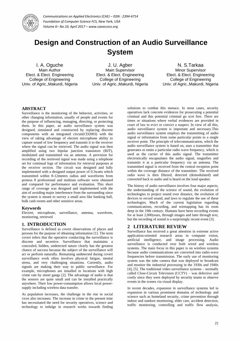
Fig. 3: Schematic diagram of FM 100MHz receiver
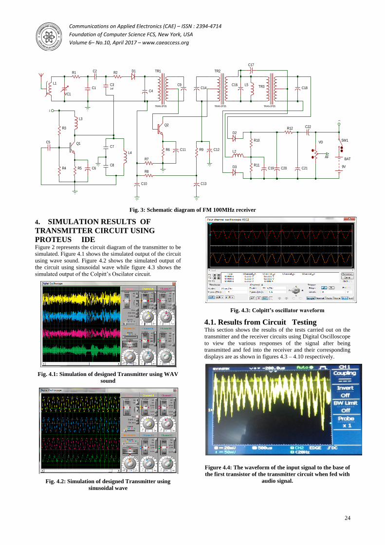
4. SIMULATION RESULTS OF
TRANSMITTER CIRCUIT USING
PROTEUS IDE Figure 2 represents the circuit diagram of the transmitter to be
simulated. Figure 4.1 shows the simulated output of the circuit
using wave sound. Figure 4.2 shows the simulated output of
the circuit using sinusoidal wave while figure 4.3 shows the
simulated output of the Colpitt’s Oscilator circuit.
Fig. 4.1: Simulation of designed Transmitter using WAV
sound
Fig. 4.2: Simulation of designed Transmitter using
sinusoidal wave
Fig. 4.3: Colpitt’s oscillator waveform
4.1. Results from Circuit Testing This section shows the results of the tests carried out on the
transmitter and the receiver circuits using Digital Oscilloscope
to view the various responses of the signal after being
transmitted and fed into the receiver and their corresponding displays are as shown in figures 4.3 – 4.10 respectively.
Figure 4.4: The waveform of the input signal to the base of
the first transistor of the transmitter circuit when fed with
audio signal.
R2
R6
C4
Q2
VC1
L1
C1
C2
C31nF
D1 TR1
TRAN-2P3S
C9
C11
TR2
TRAN-2P3S
C14
R9 C12
R5
Q1
C6
L3
R3
R4
C5C7
C8
L4
R7
R8
C10 C13
BAT
9V
SW1
1
1
R1
C16
C17
TR3
TRAN-2P3S
C18
D2
D3
R10
R11
R12
C19 C20 C21
C22
VD
AF
L2
L5
Communications on Applied Electronics (CAE) – ISSN : 2394-4714
Foundation of Computer Science FCS, New York, USA
Volume 6– No.10, April 2017 – www.caeaccess.org
25
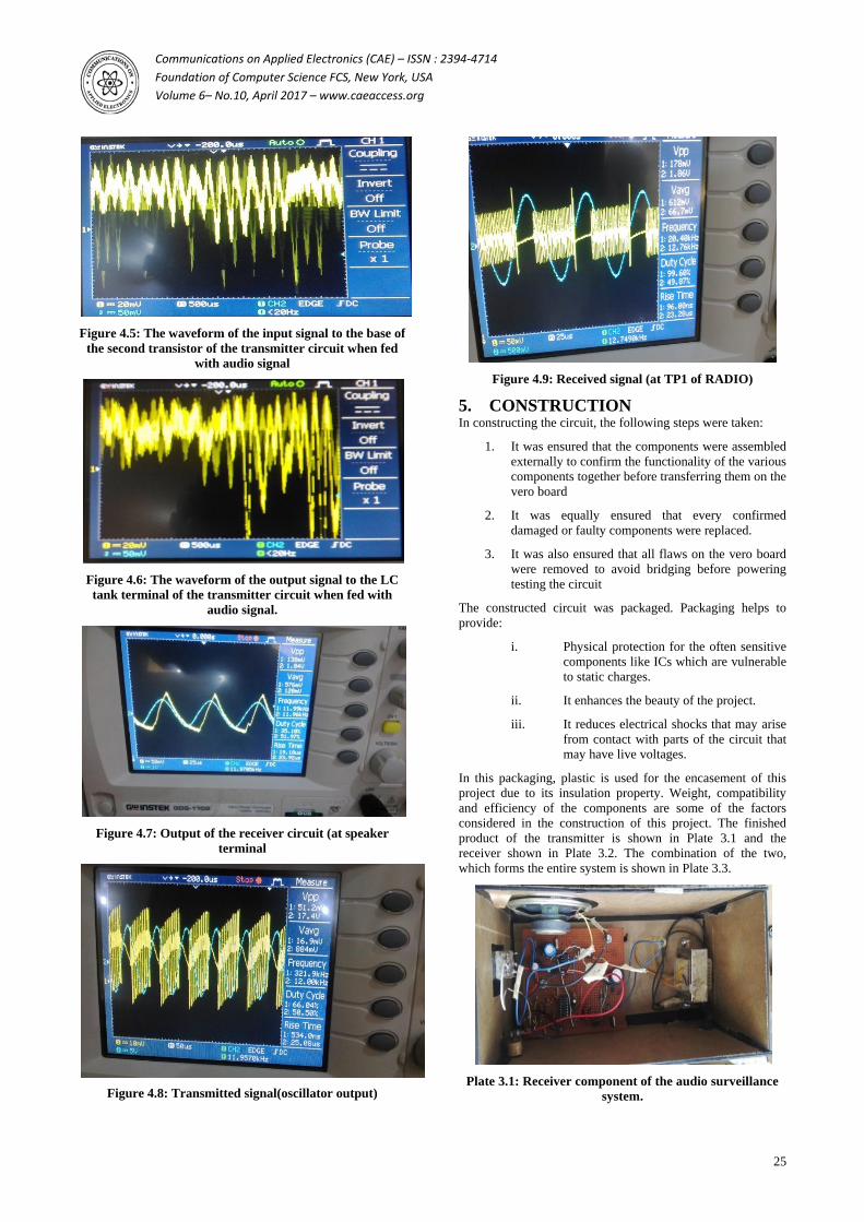
Figure 4.5: The waveform of the input signal to the base of
the second transistor of the transmitter circuit when fed
with audio signal
Figure 4.6: The waveform of the output signal to the LC
tank terminal of the transmitter circuit when fed with
audio signal.
Figure 4.7: Output of the receiver circuit (at speaker
terminal
Figure 4.8: Transmitted signal(oscillator output)
Figure 4.9: Received signal (at TP1 of RADIO)
5. CONSTRUCTION In constructing the circuit, the following steps were taken:
1. It was ensured that the components were assembled
externally to confirm the functionality of the various
components together before transferring them on the
vero board
2. It was equally ensured that every confirmed
damaged or faulty components were replaced.
3. It was also ensured that all flaws on the vero board
were removed to avoid bridging before powering
testing the circuit
The constructed circuit was packaged. Packaging helps to
provide:
i. Physical protection for the often sensitive
components like ICs which are vulnerable
to static charges.
ii. It enhances the beauty of the project.
iii. It reduces electrical shocks that may arise
from contact with parts of the circuit that
may have live voltages.
In this packaging, plastic is used for the encasement of this
project due to its insulation property. Weight, compatibility
and efficiency of the components are some of the factors
considered in the construction of this project. The finished
product of the transmitter is shown in Plate 3.1 and the
receiver shown in Plate 3.2. The combination of the two,
which forms the entire system is shown in Plate 3.3.
Plate 3.1: Receiver component of the audio surveillance
system.

Communications on Applied Electronics (CAE) – ISSN : 2394-4714
Foundation of Computer Science FCS, New York, USA
Volume 6– No.10, April 2017 – www.caeaccess.org
26
plate 3.2: Transmitter component of the audio
surveillance system.
plate 3.3: Complete units of the system consisting of the
Transmitter and the Receiver.
6. DISCUSSION PROTEUS IDE was used to simulate the transmitter and
notable result was recorded as shown in Fig 4 and 5. Also the
same software was used on the Colpitt’s oscillator that
generated the result depict Fig 7. in a similar vein, after the
construction, Fig. 8 shows the waveform of the input signal to
the base of the base of the first transistor of the transmitter
circuit when fed with audio signal and Fig. 9: The waveform
of the input signal to the base of the second transistor of the
transmitter circuit when fed with audio signal. The waveform
of the output signal to the LC tank terminal of the transmitter
circuit when fed with audio signal was depicted in Fig. 10
with Output of the receiver circuit (at speaker terminal) shown
in Fig. 11 and Transmitted signal (oscillator output) in Fig.
12, Received signal in Fig. 13. The Fig. 3 depicts the AM/FM
radio monolithic integrated circuit which is widely used for
AM/FM receivers with features such as AM HF amplifier,
local oscillator, mixer, IF amplifier, detector circuit, FM HF
amplifier, local oscillator, mixer, IF amplifier, discriminator
circuit, AGC circuit and the AM/FM band selection circuit
was used to achieve the possible result. Fig. 14 shows
waveform of the output signal from speaker terminal of the
transmitter circuit when fed with audio signal has your
transmitter circuit speaker terminals. The Fig. 15 through 17
shown the Receiver component of the audio surveillance,
Transmitter component of the audio surveillance system and
complete units of the system consisting of the Transmitter and
the Receiver respectively.
6.1 Conclusion In this research, an audio-based surveillance system was
designed and implemented using CD2003 in place of discrete
components. The performance of the system was
significantly improved by replacing the discrete components
with the\integrated circuit in the design approach. The
correlation muting system and the FLL (Frequency- Locked-
Loop) make it easy to tune and higher performance portables
and clock radios, variable-capacitance, diode tuning and
station presetting facilities were recorded.
7. ACKNOWLEDGEMENT Our thanks to the experts who have contributed towards the
development of the template.
8. REFERENCES [1] Dempsey M. 2007. ―Biometrics and the body as
information: normative issues of the socio-technical
coding of the body.‖ Surveillance as Social Sorting:
Privacy, Risk, and Automated Discrimination. Verified
Identity Pass, Inc.
[2] O’Brien, T. 2009. Public Audio Surveilance Hits
London.
[3] Peterson J. K. 2014. Understanding Surveillance
Technologies: Spy Devices, CRC Press, Third Edition.
ISBN: 084938320X
[4] Webster, W. R., Töpfer, E., Klauser, F. R., and Raab, C.
D. 2011. Revisiting the surveillance camera revolution:
Issues of governance and public policy. Introduction to
part one of the Special issue. Information Polity. 16,
297–301.
[5] Agustina, J.R., Clavell, G.G. The impact of CCTV on
fundamental right and crime prevention strategies: The
case of the Catalan Control Commission of Video
surveillance Devices. Computer law & security review.
2011, 27, 168-74.
[6] Bai, Y. W., Xie, Z. L., Li, Z. H. 2011. Design and
Implementation of a Home Embedded Surveillance
System with Ultra-Low Alert Power. IEEE Transactions
on Consumer Electronics.75153 9.
[7] Loomans, M. J. H., Koeleman, C. J. 2011. Low-
Complexity Wavelet-Based Scalable Image & Video
Coding for Home-Use Surveillance. IEEE Transactions
on Consumer Electronics, 57, 507 15.
[8] Rougier, C., Meunier, J., St-Arnaud, A., Rousseau, J.
2011. Robust Video Surveillance for Fall Detection
Based on Human Shape Deformation. IEEE Transactions
on Circuits and Systems for Video Technology, 21, 611-
22.
[9] Jeong, J., Gu, Y., He, T., Du, D. H. C. 2010. Virtual
Scanning Algorithm for Road Network Surveillance.
IEEE Transactions on Parallel and Distributed Systems.
21, 1734-49.
[10] Su, P. C., Wu, C. Y. 2010. A Joint Watermarking and
ROI Coding Scheme for Annotating Traffic Surveillance
Videos.EURASIP Journal on Advances in Signal
Processing. Pp. 1-14.
[11] Sumalee, A., Zhong, R. X., Pan, T. L., Szeto, W. Y.
2011. Stochastic cell transmission model (SCTM): A
stochastic dynamic traffic model for traffic state
surveillance and assignment. Transportation Research
Part B. 2011, 45, 507-5033.
Communications on Applied Electronics (CAE) – ISSN : 2394-4714
Foundation of Computer Science FCS, New York, USA
Volume 6– No.10, April 2017 – www.caeaccess.org
27
[12] Yuan J. L., Vehicle Surveillance with a Generic,
Adaptive, 3D Vehicle Model. IEEE Transactions on
Pattern Analysis and Machine Intelligence. 33, 1457-69.
[13] Luo, X., Wu, Y., Huang, Y., Zhang, J. 2011. Vehicle
flow detection in real-time airborne traffic surveillance
system. Transactions of the Institute of Measurement and
Control/ 33, 880–97.
[14] Monperrus, M., Long, B., Champeau, J., Hoeltzener, B.,
Marchalot, G., Jézéquel, J. M. 2013. Model-Driven
Architecture of a Maritime Systematic Review and
Classification on Video Surveillance Systems 97. MECS
I.J.
[15] Szpak, Z. L., Tapamo, J. R. 2011. Maritime surveillance:
Tracking ships inside a dynamic background using a fast
level-set. Expert Systems with Applications. 38, 6669–
80.
[16] Conte, D., Foggia, P., Percannella, G., Tufano, F., and
Vento, M. A. 2010. Method for Counting Moving People
in Video Surveillance Videos.EURASIP Journal on
Advances in Signal Processing, Pp. 1-10.
[17] Takahashi, M., Fujii, M., Shibata, M., Satoh, S. I. 2010.
Robust Recognition of Specific Human Behaviors in
Crowded Surveillance Video Sequences.EURASIP
Journal on Advances in Signal Processing, Pp. 1-14.
[18] Amato, A., Lecce, V. D. 2011. Semantic Classification
of Human Behaviors in Video Surveillance Systems.
Journal WSEAS Transactions on Computers archive, 10,
343-52.
[19] Heilmann, E. 2011. Video surveillance and security
policy in France: From regulation to Widespread
acceptance. Information Polity, 16, 369-77.
[20] Räty, T. D. 2010. Survey on Contemporary Remote
Surveillance Systems for Public Safety. IEEE
Transactions on Systems, Man, and Cybernetics—Part C:
Applications and Reviews, 40, 493-515.
[21] Paola, D. D., Milella, A., Cicirelli, G., Distante, A. 2010.
An Autonomous Mobile Robotic System for Surveillance
of Indoor Environments, International Journal of
Advanced Robotic Systems, 7, 19-26.
[22] Zhang, J., Song, G., Qiao, G., Meng, T., Sun, H. 2011.
An Indoor Security System with a Jumping Robot as the
Surveillance Terminal, IEEE Transactions on Consumer
Electronics.
[23] John W. K., 2011. Hierarchical and Modular
Surveillance Systems in ITS IEEE Intelligent Systems,
26, 10-5.
[24] Bhavya, D. 2012. Super-heterodyne FM Receiver Design
and Simulation University of Florida, Gainesville, FL,
32608, USA.
[25] Hongwu, T., and Fredrik, S. 2003. An RF Amplifier for a
FM - Radio Receiver 88-108 MHz, Radio Project,
Electroscience, Lund University.
[26] Areeb, A. 2011. Wireless USB-FM Transmitter using
ROHM Semiconductor chip in VQFP-64 Packaging PhD
fellow in Electronics & Communication, Izmir Institute
of Technology, Turkey MSc Electronics &
Communication, University of Teesside, UK 12/B.
[27] Chunbing, P. 1999. The Vision Machine, Trans. J. Rose.
London: British Film Institute.