design and construction of a movable shield for a barium oven
TRANSCRIPT

1
Design and Construction of a Movable Shield for aBarium Oven
Rebecca Schutzengel
Abstract—A moveable shield was created in order to blocklarge chunks of barium which come off a barium oven when itis initially turned on. This shield will prevent chunks of bariumfrom blocking the small hole through which barium ions shouldbe entering the chip trap. Two different actuation mechanismswere explored for the shield: first, a nitinol wire and second, abimetal strip. The nitinol wire was found to be unsuccessful butthe bimetal strip was found to be simple and reliable. Vacuumtesting was performed for a bimetal strip setup and data wascollected on the curvature of the metal as a function of thecurrent applied to it. Based on this testing, any amount of currentbetween 1 and 2 amps is predicted to be sufficient to cause theshield to block the barium oven, while passing no current throughthe bimetal will unblock the oven, allowing the trap to be loaded.
I. BACKGROUND
ION trapping has many potential applications in atomicphysics. It is possible to use trapped ions to create ion-
photon entaglement. This entanglement can be used to run aloophole-free tests of Bell’s Inequality. Another application ofion trapping is the creation of a scalable quantum computer.Trapped barium ions can be used as qubits where the spin-up and spin-down states of the outermost electron correspondto the 0 and 1 states in a conventional computer. Usingsuperposition of states, algorithms for quantum computinghave the potential to be highly more efficient than traditionalcomputing algorithms. For example, Shor’s algorithm wouldallow a quantum computer to factor large numbers much fasterthan is possible with any currently existing computer. Theimplementation of such an algorithm would have profoundimplications for computer security since current encriptionschemes rely on the impossibility of factoring very largenumbers efficiently.
II. PHYSICAL SYSTEM
In order to trap individual barium ions, we must firstgenerate a stream of barium atoms. This is accomplished usinga barium oven in which solid chunks of barium are heated tovery high temperatures, causing an atomic beam to be emitted.Directly above the barium oven there is a small hole throughwhich the barium atoms can enter the chip trap.
One pitfall of the above design is that as the oven is initiallybeing heated relatively large chunks of barium are released.These pieces are large enough to block the hole through whichatoms should be escaping, and therefore derail the actualexperiment. In order to solve this problem, we created a shieldwhich is held over the oven while it is initially being heated,then moved out of the way when experiments are ready to
begin. This shield may also be used repeatedly to block atomsfrom entering the system after an ion has been trapped, butallow more atoms through at a later point in time if a trappedion is lost.
III. DESIGN WITH NITINOL WIRE
The first iteration of our design used Nitinol wire to actuatethe movement of the shield. Nitinol is a nickle-tin alloy thatbelongs to a larger class of materials known as shape-memoryalloys (SMAs). These alloys can be ”trained” by holdingthem at high temperatures for at least five minutes and thencooling them quickly. While cold, the SMA can be bent intowhatever shape is desired and when the SMA is heated abovean activation temperature it will return to the shape it wastrained to.
Figure 1 shows a schematic of the original design withNitinol wire and springs holding the shield. In this design,the nitinol is trained into a sharply bent shape and is loopedthrough one end of a sheet metal shield. Springs are attachedto the other end of the shield such that they pull and causethe nitinol to unbend when it is cold. This design was testedand found to be incapable of creating repeatable movementover a large enough distance. The pulling strength of thenitinol wire when heated was not significantly greater thanthe strength with which the cold nitinol wire resisted shapechanges. Therefore, any springs which were weak enough tobe extended by the hot nitinol wire were also too weak toextend the cold nitinol wire significantly.
Two other nitinol setups were also tested and found toexhibit the same shortcoming. In one setup, two differentpieces of nitinol wire were attached on either end of theshield. In this case, the pieces could be made to have differentstrengths by heat training them for different amounts of time.However, this variation in timing affected both the hot strengthand the cold strength of the wire. As a result, regardless ofthe conditions of the shape setting, alternate heating of the twowires caused the system to reach an equilibrium configurationin which neither wire could create any further movement whenheated. The final nitinol configuration tested was to shape setthe nitinol into a helix and attach it to the shield such thatit pulled against a spring. This setup was also found to beinfeasible for the same reasons as the original setup.
IV. USE OF BIMETALLIC STRIPS
A. Design
Bimetallic strips are strips of metal in which two metals withdifferent coefficients of thermal expansion are fused together

2
Fig. 1. Original shield setup design. Sheet metal shield pulled in opposingdirections by nitinol wire and springs.
side-by-side. When a bimetallic strip is heated, one side of itbecomes longer than the other, causing the strip to curl intoan arc such that the metal with greater thermal expansion ison the outside. Upon cooling, the bimetal will automaticallyuncurl as the two sides return to equal lengths. In our seconddesign, we used this motion as the driving mechanism for theshield.
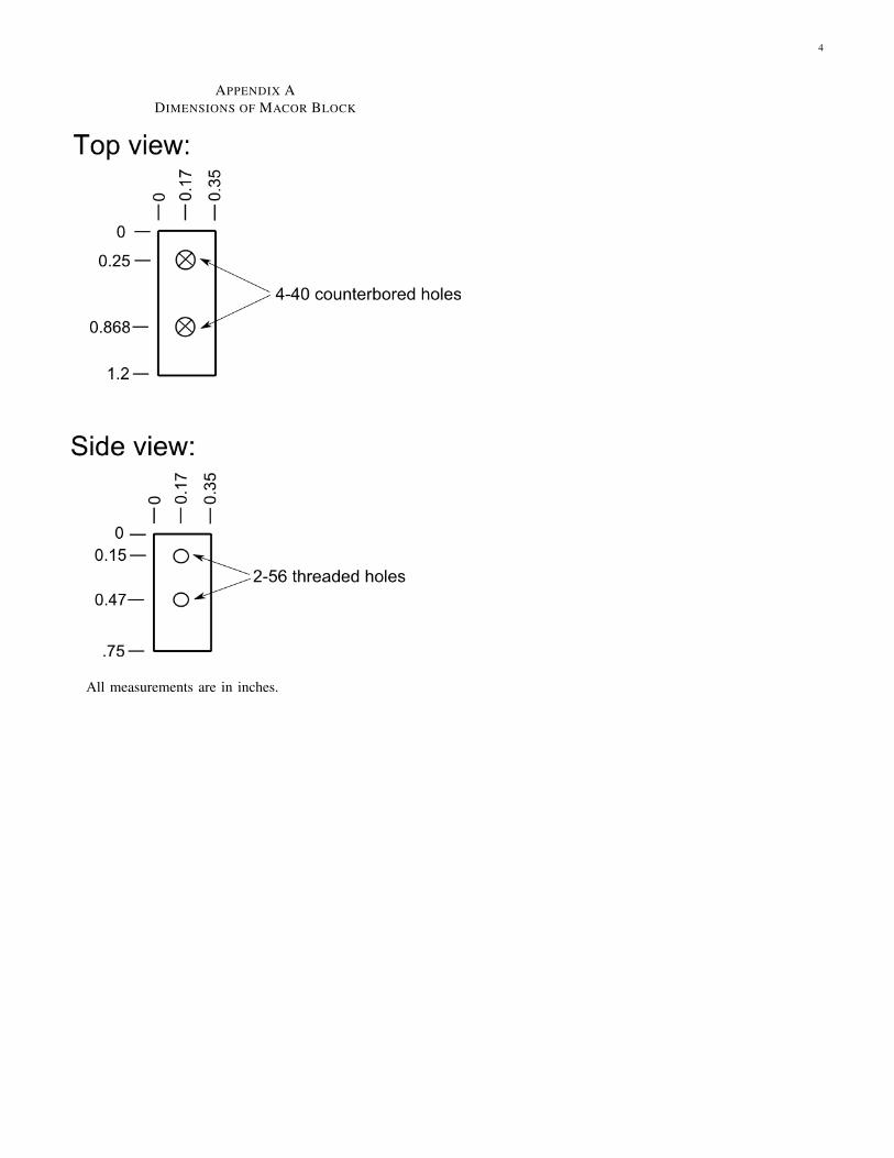
Figure 2 shows a schematic of the setup used for thebimetalic strip. Precise dimensions are shown in Appendix A.Bimetallic strips were manually cut into the desired lengthand shape, which was chosen in order to make resistiveheating possible with reasonable levels of current. The bimetalstrip was then screwed into a macor block designed to fitunderneath the chip trap in the current trapping setup. Heatingwas accomplished by passing current through the bimetalstrip. Greater amounts of current were found to induce moresignificant curvature in the metal.
B. Vacuum Testing
A simple vacuum test of the bimetal setup was performedin a bell jar. Due to space constraints, the macor block wasnot included in the vacuum test. Instead, the bimetal strip wasconnected directly to two feedthrough electrodes. A bariumoven was also included in the vacuum test in order to ensurethat the heat from the oven would not cause the bimetal tobend. Images from the vacuum test are shown in Figure 3. Itis clear from Figures 3(a) and 3(b) that radiative heat fromthe barium oven is not sufficient to cause bending of the thebimetal. As shown in Figures 3(c) and 3(d), the bending ofthe bimetal strip can be reliably controlled by the amountof current applied to it. Noticeable bending begins around0.5 amps of current and the curvature increases continuallyas greater amounts of current are applied. The bimetal will
Fig. 2. Schematic of shield setup using bimetal strips.
(a) No current, oven off (b) No current, oven on
(c) 1 amp current, oven on (d) 3 amps current, oven on
Fig. 3. Barium oven, bimetal strip and shield inside vacuum. Heat from theoven does not cause the bimetal strip to bend, but resistive heating does whena current of 1 amp or more is applied.
consistently return to the same shape each time a given amountof current is applied. These results indicate that a bimetal stripwill be a reliable actuation mechanism for shielding the bariumoven.
C. Curvature Predictions
Once the oven shield is put in place and pumped to ultrahighvacuum, it will be difficult for an observer to view theoven shield. Therefore, it is necessary to be able to predictthe bimetal curvature as a function of applied current. Thisprediction will determine how much current must be appliedin order for the barium oven to be shielded. In order to makethis prediction, we measured the curvatures of the bimetal stripunder three conditions: in vacuum, in the vacuum setup butat atmospheric pressure and in the final setup at atmosphericpressure. The results of these measurements are shown inFigure 4. It is seen that for currents between 1 and 4 amps,the radius of curvature of the bimetal depends exponentiallyupon the current applied.
We also see in Figure 4 that the bimetal bends more (hasa smaller radius of curvature) when heated in vacuum than itdoes when heated in air. This is expected because in vacuumthe bimetal strip is not cooled through convection as it is in

3
Fig. 4. Bimetal curvature as a function of current applied.
air, so the strip reaches higher temperatures in vacuum, whichcauses it to bend more. We also see from comparison of thetwo curvature tests run in air that the bimetal strip to be usedin the final setup consistently bends less for a given amountof current than the bimetal strip that was used in the vacuumtest (this is shown by the vertical offset between the green andblue lines). This is most likely due to the different lengths ofthe two bimetal strips. Therefore, we predict that the sameamount of offset will be present when comparing the finalsetup in vacuum to the test setup in vacuum. The predictedpurple line in Figure 4 was made based on this assumption.
In air, the bimetal strip in the final setup required a current ofat least 2.5 amps in order to bend enough to block the bariumoven. 3 amps of current was ideal, as it reliably centered thesheet metal shield over the barium oven, and 4 amps wasthe maximum that could be safely applied while ensuring thatthe bimetal strip did not come in contact with the oven. Bymatching the radius of curvature observed at each of thesecurrent levels to the predicted radius of curvature in vacuum, itwas found that the maximum current that should be applied tothe bimetal strip in vacuum is 3 amps, and the ideal current tocompletely cover the oven (equivalent to 3 amps in air) is 1.3amps. There is no prediction for the absolute minimum currentnecessary (equivalent to 2.5 amps in air), as that numberwould be lower than 1 amp, and therefore not within thedomain for which our linear predictions are reliable. From
these predictions, it is suggested that between 1 and 2 ampsof current should be applied to the bimetal strip in vacuum inorder to fully block the barium oven, and no current shouldbe applied when loading the trap.
V. CONCLUSION
This paper presented the design and testing of a movablesheet metal shield to be placed in an ion trapping system. Theshield is actuated using a bimetal strip, which was found tobe capable of consistent, repeated movement when resistivelyheated. When activated with current, the bimetal strip bendsand moves a sheet metal shield over the barium oven, therebypreventing barium chunks from clogging the entrance to thechip trap. When current is removed, the bimetal strip returns toits original shape, unblocking the oven and allowing ions to beloaded into the trap. Based on vacuum testing, it is predictedthat for the bimetal strip to be used in the chip trap setup,a any current between 1 and 2 amps will reliably cause thebarium oven to be shielded.
ACKNOWLEDGEMENTS
Thanks to Boris Blinov, Tom Noel and the rest of theTrapped Ion Quantum Computing Lab for all their help onthis project. Thanks also to Alejandro Garcia, Deep Gupta,Janine Nemerever and Linda Vilett for organizing the REUprogram. Finally, thank you to the NSF for funding the REU.
4
APPENDIX ADIMENSIONS OF MACOR BLOCK
All measurements are in inches.