design and construction of a low cost offset parabolic...
TRANSCRIPT

DESIGN AND CONSTRUCTION OF A LOW COST OFFSET PARABOLIC SOLAR CONCENTRATOR FOR SOLAR COOKING IN RURAL AREAS
Javier Diz-Bugarin1
1 Dept. Electronics, IES Escolas Proval, Nigran (Spain)
1. Introduction
In this paper will be presented the process of design and construction of a low cost solar concentrator for cooking in remote areas and underdeveloped countries. To avoid complexity of design of an specific shaped surface a common offset parabolic antenna is used to make the reflector. This type of antennas are widely used both in developed and underdeveloped countries, are cheap and easy to obtain. The parabolic reflector is placed under the pot almost horizontally, specially at midday when the sun reaches elevations of around 65 degrees.
This configuration offers many advantages over most common centered-focus solar cookers, like lower wind resistance and higher stability of the structure because of lower center of gravity. It also produces vertically reflected rays that reach the food pot at the bottom like in conventional stoves. Offset parabolic reflectors are more efficient since objects placed at the focus don't create shadows over the reflecting surface.
Different types of reflective surfaces have been tested, like aluminium foil and metalized polypropylene sheets.
The paper also describes the prototype construction process and test with a parabolic dish of 80 cm diameter.
With offset parabolic reflectors it is possible to combine two reflectors that focus at the same point, a configuration that is not possible with centered focus parabolic reflectors. Also a transparent cover can be placed around the pot except by its base, reducing heat losses.
This type of device has a security issue due to vertical incidence of radiation that can cause burns and eye injuries. A proposed solution is to cover the cooking area with a dark surface and protect the focal point with a lid when not in use.
Fig. 1 shows one of the first prototypes of this type of cooker.
Fig. 1: Prototype of offset solar concentrator with a 80 cm diameter parabolic dish
2. Parabolic cooker construction
Many types of parabolic solar cookers have been developed over the years (Kundapur, 2010). The main complication of the construction of a parabolic cooker is to obtain a structure with the curvature required to reflect the sunlight towards the focus. To avoid this difficulty any of the following methods can be used:
Obtaining a mold from a satellite reflector antenna and make a reproduction in another material such as fiberglass, polyester resin or epoxy. It can also be done with more conventional materials. The surface has to be covered with a reflecting material like small pieces of mirror or a metallized plastic sheet.

Covering a satellite antenna reflector with small pieces of mirror, forming a mosaic that depicts the curvature of the parabola. This method has the advantage of the ease of obtaining the material, especially in developing countries. Instead it has the problem of high weight and low mobility of the parabola.
Coating of a satellite antenna reflector with a highly reflective material such as metallized polyester, polypropylene or mylar. It's a good solution if there is easy access to necessary materials.
3. Types of parabolic reflectors
Centered focus reflector in which the focus is located on the axis of symmetry of the parabola. They have the problem that objects situated in the focus project shadows on the reflector as seen in Fig. 2, reducing the efficiency.
Centered focus parabolic
Fig. 2: Radiation incidence in a centered-focus parabolic reflector
Displaced focus reflectors (offset): in this type the focal point is outside the reflector area and does not project shadows as seen in Fig. 3, increasing the efficiency.
Ofset parabolic
Fig. 3: Radiation incidence in an offset-focus parabolic reflector
Offset reflectors with angle of elevation: this type of reflector focuses the radiation with a certain elevation, typically about 25 degrees (Televes, 2010), like in Fig. 4. Thus the position of parabola can be almost vertical for typical satellite reception, which facilitates placement in buildings, etc. They are the most common type of satellite antennas.
This type of reflector has the advantage of its low price and availability. When used as a solar concentrator, the typical elevation angle of the sun at midday allows the reflector to be in horizontal position, specially in summer and for latitudes about 40º (for example in Spain).
This is the parabolic reflector that will be used in this prototype of solar cooker.

Elevation angle
Offset parabolic with elevation angle
Fig. 4: Offset reflector with elevation angle
4. Design and assembly criteria
The following criteria have been taken into account in the design of the cooker:
The characteristics of the offset parabolic reflector allow to place it in horizontal position, what gives more stability, offers less resistance to wind and directs solar rays towards the base of the pot the same way as in conventional stoves. It may be necessary to adjust the angle of the reflector in a certain range to match the elevation angle of the sun at different times of day and seasons. This angle can be a maximum of 30 degrees in many situations. The design of the cooker frame must allow this displacement of the reflector.
Summer position Winter position
Fig. 5: Offset reflector position in different seasons
The pot should not be placed exactly at the focus of the parabolic, but vertically shifted a few centimetres, so that there is not a very small focus point that could reach very high temperatures. Instead there will be a “focus zone” of about ten centimetres diameter, with a uniform distribution of temperature. It is preferable that the pot remains above the focus (rather than underneath) so that no shadows occur on the reflector. Fig. 6 shows one of the first tests made to locate the focal point of the cooker and to determine the size of the focal zone in different vertical positions.
Fig. 6: Finding the focal point of the offset reflector
The thermal power of the cooker surface is related to the reflector size, which has a circular shape.

As an example, a dish of 80cm diameter has an area of 0.504 m2, for an incident radiation 1000Wm-2 and a performance of approximately 60% gives a power of 300W, equivalent to a small electric heater. In this power calculation it was not taken into account the direct radiation captured by the pot, that can achieve a significant value.
5. Construction of the reflector
Our prototype of solar cooker is based in an offset satellite antenna with a diameter of 80cm. This element has good reflecting properties in the range of microwaves, but is not suitable as a solar reflector. An option to improve its characteristics is cover the parabolic surface with a reflecting material like aluminium foil or metallized polypropylene.
Aluminium foil: this material is cheap and easy to obtain, but when placed outdoors suffers an important loss of reflectivity due to dust or oxidation.
Metallized polypropylene: this material has better properties than aluminium foil. It can be obtained in many places as wrapping paper rolls.
Aluminium or polypropylene must be cut into pieces that can be triangular, square or rectangular shape. The size of each piece should be as large as possible, provided there are not too many wrinkles. Squares of 10x10cm or narrow triangular pieces are good solutions.
Fig. 7: Different types of reflective cover: polypropylene film (triangular pieces) and aluminium foil (square pieces)
If triangular pieces are used, each triangle should cover at least 15 degrees of the parabola (24 strips in total), if they are larger could not follow the curvature of the parabola and if they are smaller the assembly is more complicated and slow. Fig 8 shows the cutting diagram for a polypropylene sheet, and Fig. 9 shows the cutting process.
10cm
40cm
15º
Fig. 8: Cutting diagram of the reflective film
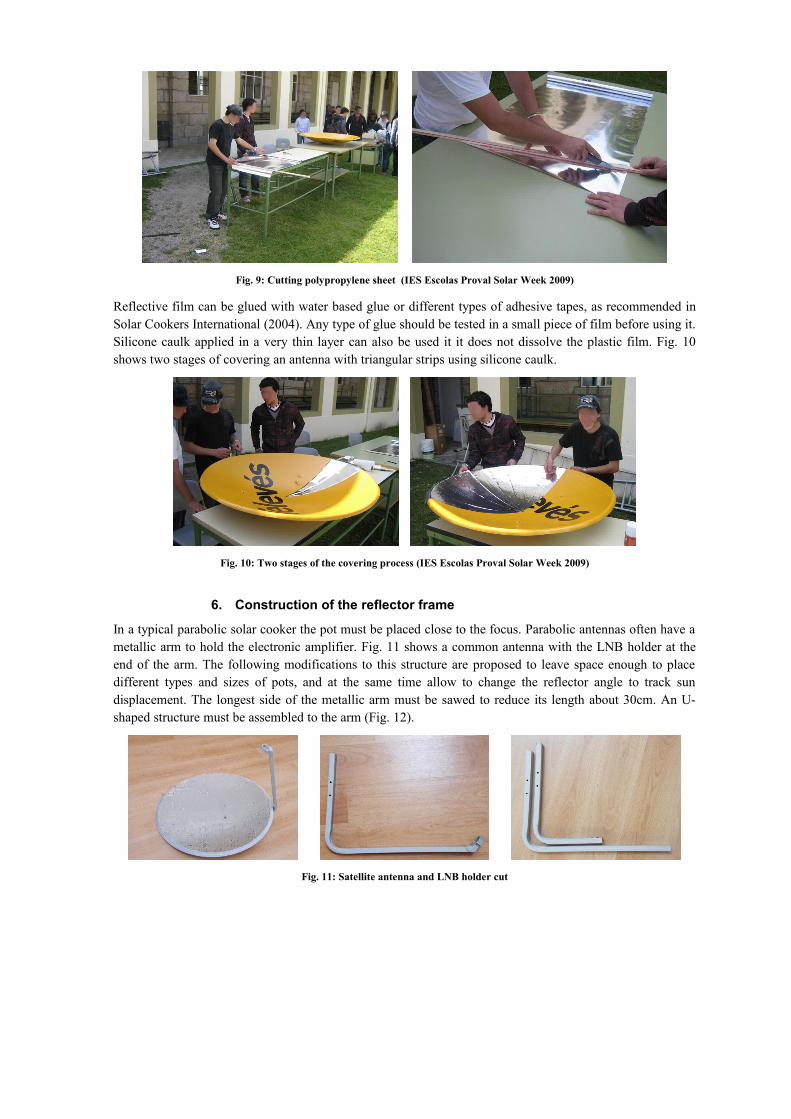
Fig. 9: Cutting polypropylene sheet (IES Escolas Proval Solar Week 2009)
Reflective film can be glued with water based glue or different types of adhesive tapes, as recommended in Solar Cookers International (2004). Any type of glue should be tested in a small piece of film before using it. Silicone caulk applied in a very thin layer can also be used it it does not dissolve the plastic film. Fig. 10 shows two stages of covering an antenna with triangular strips using silicone caulk.
Fig. 10: Two stages of the covering process (IES Escolas Proval Solar Week 2009)
6. Construction of the reflector frame
In a typical parabolic solar cooker the pot must be placed close to the focus. Parabolic antennas often have a metallic arm to hold the electronic amplifier. Fig. 11 shows a common antenna with the LNB holder at the end of the arm. The following modifications to this structure are proposed to leave space enough to place different types and sizes of pots, and at the same time allow to change the reflector angle to track sun displacement. The longest side of the metallic arm must be sawed to reduce its length about 30cm. An U-shaped structure must be assembled to the arm (Fig. 12).
Fig. 11: Satellite antenna and LNB holder cut

Fig. 12: U-shaped structure and parabola assembly
All the pieces of the reflector frame must be screwed with stainless M8 screws and nuts as seen in Fig 13.
Fig. 13: Reflector frame assembly
The solar cooker can easily be folded for storage or be completely disassembled for storage or transportation (Fig. 14). Asembly plans and detailed description of parts with dimensions and drills can be found in Fig. 15 and Fig. 16.
Fig. 14: Solar cooker folded and disassembled

M8
M8
M8
M8
M8
M8
M8M8
M8 M8
M8
M8
M8
Fig. 15: Solar cooker assembly plan
1000
8020
50
1000
10
x4 x1
30
x1
1000
920
340
460
x1
x2
10
10
30
2010
1030
Fig. 16: Solar cooker parts and dimensions
7. Use and performance tests
This type of solar cooker produces vertically reflected rays that reach the food pot at the bottom like in conventional stoves. So many types of pots and recipients can be used. Moreover, heat traps can be placed around the pot (except by his bottom) without risk of burning or damage. Polyester or nylon oven bags are particularly suitable for this application. Pyrex glass recipients are also good options. Fig. 17 shows two examples of use of the cooker for making coffee and baking chestnuts.
The power obtained with this solar cooker is not high because of the small size of the reflector. A few improvements are planned, like using a larger parabola and combining two reflectors that focus at the same

point, a configuration that is not possible with centered focus parabolic cookers. On the other hand, it shows a high stability even in the presence of wind and is easy to adjust and fold for storage and transportation.
This type of device has a security issue due to vertical incidence of radiation that can cause burns and eye injuries. A proposed solution is to cover the cooking area with a dark surface and protect the focal point with a lid when not in use.
The reflective film can suffer from an important loss of reflectivity due to dust or oxidation. In this case can be necessary to replace it periodically, for example one a year.
Fig. 17: Different uses of the solar cooker
8. Acknowledgements
The author wishes to thank all the staff and students at IES Escolas Proval for their cooperation in solar activities that were carried out at the centre, specially to students of DPE 2008-2009.
9. References
Solar Cookers International, 2004. Solar Cookers: How to make, use and enjoy, 10th ed., Sacramento, California.
Televes, http://www.televes.com/es/catalogo/producto/antena-hierro-set-800-naranja-embalaje-unitario, 2010, last accesed 07/30/2011
Kundapur, A., http://solarcooking.wikia.com/wiki/Parabolic_solar_reflectors, 2010. last accesed 07/30/2011