design and construction of a 0.5 kw solar tree for ... · design and construction of a 0.5 kw solar...
TRANSCRIPT
http://www.iaeme.com/IJMET/index.asp 19 [email protected]
International Journal of Mechanical Engineering and Technology (IJMET)
Volume 10, Issue 06, June 2019, pp. 19-33, Article ID: IJMET_10_06_003
Available online at http://www.iaeme.com/ijmet/issues.asp?JType=IJMET&VType=10&IType=6
ISSN Print: 0976-6340 and ISSN Online: 0976-6359
© IAEME Publication
DESIGN AND CONSTRUCTION OF A 0.5 KW
SOLAR TREE FOR POWERING FARM
SETTLEMENTS
Ifetayo Oluwafemi
Postgraduate School of Engineering Management, University of Johannesburg,
RSA, Johannesburg, 2006, South African
Timothy Laseinde
Department of Mechanical and Industrial Engineering, University of Johannesburg, RSA
Ayodeji Olalekan Salau Department of Electrical/Electronics and Computer Engineering,
Afe Babalola University, Ado-Ekiti, Nigeria
ABSTRACT
Nigeria is a country faced with great challenges in the power sector. This is as a
result of inadequate administrative and technical efforts in handling issues in this
sector. Aforetime, the country has solely depended on grid electricity generation
which has proven to be unstable for several decades. These and others, has made it
imperative to introduce the use of renewable energy in addressing some of the
electricity challenges facing the country. The sources of renewable energy which
could serve as an alternative source of power include wind, solar, and biogas. These
can also be combined together as an entity to form a hybrid renewable energy source.
In this paper, a solar tree was designed and constructed to provide an alternative
supply of electricity to farm settlements in Nigeria. This is achieved by generating
electricity from a single or multiple number of solar panels connected with a charge
controller, a battery bank for storage and an inverter circuit to supply electrical
power. Depending on the electrical load demand and the applications coverage area,
the solar tree rating and specification can be a single-phase or three-phase AC output.
Key words: Solar Tree, Grid, Electricity, Renewable Energy, Power
Cite this Article: Ifetayo Oluwafemi, Timothy Laseinde and Ayodeji Olalekan Salau,
Design and Construction of a 0.5 kW Solar Tree for Powering Farm Settlements.
International Journal of Mechanical Engineering and Technology 10(6), 2019, pp. 19-
33.
http://www.iaeme.com/IJMET/issues.asp?JType=IJMET&VType=10&IType=6
1. INTRODUCTION
Nigeria has limited sources of non-renewable fuels. Most power generating stations today use
conventional fuels such as coal and natural gas. To minimize the dependence on these

Ifetayo Oluwafemi, Timothy Laseinde and Ayodeji Olalekan Salau
http://www.iaeme.com/IJMET/index.asp 20 [email protected]
sources, the country must move on to new and renewable energy sources like solar, wind, etc.
Currently, due to the increase in Nigeria‟s population, the countries energy demand has
drastically increased. Therefore, it has becomes highly imperative to investigate other sources
of generating electricity; hence, the option of renewable energy sources was considered. It is
important to also put into consideration some factors which should be included while seeking
an alternative energy source. These are pollution as well as natural hazards. In consideration
of the harmful effect of non-renewable fuels or sources of power we sought for an alternative
means of energy and realized the option of the solar power energy has been found to be
suitable with fewer hazards and adverse health implications.
Statistically, the total electricity generation in Nigeria presently is believed to be
around 4,000MW, though there are efforts in place to improve it beyond 10,000MW in
the year 2020 and more in subsequent years as planned by the Federal Government of
Nigeria [1]. At present, the current power generation is not up to half of the demand for
electricity which is 12,000MW. More recently, the power demand has been forecasted to
grow to about 45,000MW by the year 2020 due to the constant increase in population. Oseni
[2] in his study, emphasized that most Nigerian household‟s witness power failure for about
19 hours daily.
The use of renewable energy sources to generate electricity is a good option to help boost
the generation of electricity supply. These renewable energy sources include solar, wind,
geothermal heat and so on, which are also combined to form hybrid renewable energy systems
[3], [4], [5].
According to Obasi [6], the Nigerian Association of Energy Economists (NAEE) said
that in spite of the data signifying that 45% of the country‟s population is presently linked
to the national grid, constant power supply is still limited to just about 25% of the
population. Preference is given to people leaving in the cities than those who are
domiciled in the rural area in terms of electricity availability. Those who stay in the cities
tend to have more frequent power supply than those staying in rural areas. The NAEE has
expressed worry over the economic redundancy in these parts of the country. Some of the
challenges outlined include:
The high cost of electricity.
Lack of electricity in rural areas
Environmental pollution.
Inadequate transmission and distribution of electricity.
Ouedraogo [7] stated that there are efforts made by the Federal government to ensure a
stable power supply. Although with all the effort made, the country still experiences several
challenges in the power sector. The author proposed a scenario-based framework which was
able to quantitatively analyze the present status of electricity generation in the country and
which has the capability to predict the likelihood of the future generation profile as well
as its associated global warming potentials. The framework developed in [7] also finds
use for planning and analyzing likely ways for ensuring regional electricity expansion
and could also be used to explore alternative potential scenarios to achieve universal
access to electricity. The framework entails the deployment of renewable energies and
demand and supply-side energy efficiency policies.
The rest of this paper is organized as follows. A review of related works is presented in
Section 2. Section 3 provides details of our proposed method and in Section 4, details of the
experimental results are discussed. Lastly, in Section 5, we draw the conclusion of our work
and discuss the directions for future work.

Design and Construction of a 0.5 kW Solar Tree for Powering Farm Settlements
http://www.iaeme.com/IJMET/index.asp 21 [email protected]
2. LITERATURE REVIEW
A solar tree is an attractive system designed to produce electricity. It basically makes use of a
single or multiple number of solar panels, a charge controller, a battery bank for storage and
an inverter circuitry to supply electrical loads [8], [9]. Depending on the electrical load
demand and area of application, a solar trees rating and specification can provide a single-
phase or three-phase AC output. A Solar tree is a stylish uniquely designed superstructure
with mounted solar panels for lighting, remote power, and feeding-tariff applications [10].
The Solar Tree is a functional and ornamental design for public spaces and private grounds.
Comparatively, Solar Trees prove to be the most beneficial source of energy. This project
presents the implementation of a Solar tree as an alternate source of energy in rural areas. It is
basically a combination of sun-tracking solar panel mounts and a standalone AC to DC
system.
2.1. History of Electricity Power Supply in Nigeria: The Development So Far
It was stated in Ubi [11], that the Federal Government of Nigeria has made a substantial
reformation in the power sector of the country. From previous studies, it was mentioned that
there are three noticeable periods of major development in the power sector. One of the
notable periods is said to be the time Electricity Corporation of Nigeria, known as ECN was
founded, in the year 1950 [12]. The ECN is a secluded electricity generation facility with a
minute electrification access. During this era, electricity supply in Nigeria was strictly
confined to cities and a few industrial areas. There were some establishments of a few power
plants for electricity generation in this period. A power plant was built in Ijora area of Lagos
State in the year 1898 [13]. The project was practically achieved through the colonial
government with the authority and involvement of the department of public works, which is
one of the government agencies. After this establishment, some other plants were set up by
native and municipal authorities. Furthermore, a private investor, The Nigeria Electricity
Supply Company (NESCO) constructed the 2MW hydroelectric power plant at Kurra, very
close to Jos, in Plateau State in 1929 [14]. African Timber and Plywood Limited, constructed
another Power plant in Sapele in Delta State, which started full operation in 1930 [15]. Shell
Development Company of Nigeria established a power plant at Bonny highland in Rivers
State as well as in Delta State in the year 1942 [16].
The 2nd
phase was the period when the National Electric Power Authority known as
NEPA was established in the year 1972 [17]. To ensure smooth operation of this power
plants, there was a need to integrate the ECN with NDA for adequate management of the
plants. As part of the reforms achieved earlier, ECN was saddled with the responsibility of
electric power generation, transmission, distribution and sales across Nigeria. Also, ECN was
licensed to acquire, grip and dispose-off lands for drive active processes in their operations
and actualizing their desired goals of ensuring adequate and regular electricity supply in
Nigeria. The Niger Dam Authority of Nigeria (NDA) was founded immediately after the
establishment of the Niger Dam Hydroelectric project at Kanji in 1962. The NDA was
saddled with the responsibility of supervising the progress of hydroelectric facilities
establishment in Nigeria [11]. The body was saddled with the responsibility of building and
sustaining dams and many other projects in the river Niger and in other areas in Nigeria. They
were tasked with the responsibility of producing electricity via the use of water through dams,
enlightening triangulation and endorsing fishing activities and irrigation.
In the 3rd
Phase, after the establishment of the National Electricity Power Authority
(NEPA), and other bodies like NDA and ECN. Despite all efforts put together to establish all
these bodies with the primary objective of ensuring a stable power supply in the country, the
country still has challenges in the power sector. The Federal Government of Nigeria had to

Ifetayo Oluwafemi, Timothy Laseinde and Ayodeji Olalekan Salau
http://www.iaeme.com/IJMET/index.asp 22 [email protected]
merge both NDA and ECN together. In 1971, the Federal government contracted a Canadian
firm as a consultant to investigate the activities of the two organizations and come up with a
report which was useful in addressing the prevalent challenges of power supply in the
country. The outcome of the reports submitted by the consultants made the Federal
Governments of Nigeria establish the National Electric Power Authority (NEPA) via the
merger of ECN and NDA. A law was established to grant NEPA the legal mandate to
preserve, coordinate, and maintain the economic system of electricity supply across Nigeria.
This was how NEPA became a government-controlled body, which oversaw nearly all
activities of the power sector in the country, including production, transmission, and
distribution of electricity to end consumers. Table 1 presents the locations of the power
stations, the types and their year of establishment.
Table 1 Name of power station, type and year of establishment.
Location of power station Type of power station Year of establishment
Ijora Thermal 1956
Afam Thermal 1962
Delta Thermal 1966
Kanji Hydro 1968
Ogorode Thermal 1980
Jebba Hydro 1985
Lagos Thermal 1986
Shiroro Hydro 1989
This study presents the design and construction of a solar tree power system which
generates electricity at the point of usage. We obtained a maximum energy output
through a solar panel tracking system which was incorporated in the design. This
approach is presented to proffer an alternative solution to the power challenges
experienced by the populace in the rural areas.
3. METHODOLOGY
This section provides a detailed discussion of the processes and design procedure employed
in the design of the solar tree system. The methods include the design of the inverter,
charge controller, calculation of load requirements, battery selection based on calculated
load requirements, solar panel selection based on efficiency and cost, the design of solar
tracking circuit, and the design of solar tree framework.
3.1. Design of Solar Tree System Components
The block diagram of a typical Solar-Inverter System is shown in Fig. 1. Fig. 1 shows the
major components required by a solar tree system and how they interact with each other. In
Table 2, we present the components used for the design and construction.
Figure 1 Block diagram of the Solar Tree system.
Design and Construction of a 0.5 kW Solar Tree for Powering Farm Settlements
http://www.iaeme.com/IJMET/index.asp 23 [email protected]
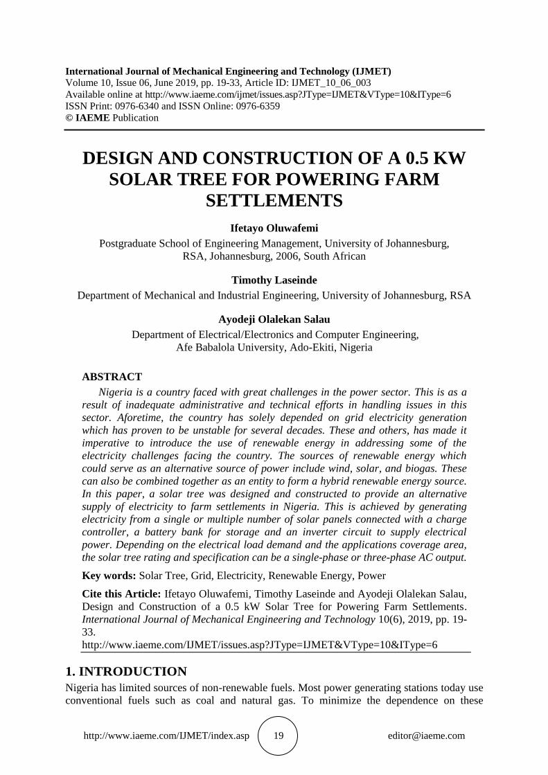
Table 2 Components used for the design of the inverter.
Components required for the
construction of the inverter
Components required for
building the oscillatory circuit
Other components
IRFP260N 300W
power MOSFET
SG3524 Microcontroller, 104
variable resistors, Four 103
resistors, Two 104 resistors, and
one 2.2μF capacitor
12V to the 220V
step-up transformer,
Two fuse holders,
one „on‟ and „off‟
switch,
a miniature circuit
breaker, a socket
outlet, input and
output meters, and a
power indicator
Two 100kΩ resistors
Four 103 resistors, Two 104
resistors, one
2.2μF capacitor, 7808 voltage
regulators, one 560 ohms‟
resistor, one 330 ohms‟ resistor,
one 10nF capacitor, and one
100K resistor
Four 1kΩ resistors
One 100μF capacitor, Two
BC547 NPN
transistors, and a 1n4007 diode
3.2. System Requirements
The design, implementation, and installation of the solar tree stand-alone system is a
tasking job. Before the system implementation, a thorough analysis of the requirements
needed to complete the system was done. This step was necessary as it helped to provide
the necessary guidelines for the implementation. The solar tree was designed in such a
way that it provides electricity at the point of usage i.e. the energy harnessed from the sun
is not only converted into DC and stored in the battery for usage, but the DC can be
inverted into AC and supplied to the lighting points which serve as the branches of the
tree. In addition, an AC socket outlet is provided at the base of the tree giving out the
220V-240V AC rating compatible with domestic appliances like television, radio, mobile
phones and laptops. The load analysis of the solar tree is presented in Table 3.
Table 3 Load analysis of the Solar Tree.
Table 3 shows that the tree has two lighting points each consisting of 18 Watts energy
saving light bulb, and two AC socket outlets. Since the total load to be powered is
516Watts which is approximately 550Watts, we use a power factor rating of 0.85, the
kVA rating of the inverter is calculated as:
Inverter in kVA = Total load in watts / power factor (1)
Therefore, the required kVA rating of the inverter = 550/0.85 = 647.06VA (2)
For a maximum load tolerance, a 750VA, 12V DC was used as the design
specification of the inverter in this work.
3.3. Design of Inverter System
This section provides the procedure, design and construction of components of the 750VA
power inverter, specifically designed to power some domestic appliances used in the home
and offices. This design can last for at least a day, depending on the load on it, the number of
Load Quantity Watt (W) Total Capacity
Light points 2 18 36
Charge point 2 240 480
Total 4 258 516
Ifetayo Oluwafemi, Timothy Laseinde and Ayodeji Olalekan Salau
http://www.iaeme.com/IJMET/index.asp 24 [email protected]
battery banks in use and the rate at which batteries are being charged by the photovoltaic
(PV) cells. This increases the comfortability of users. The inverter is designed to meet the
specification and the functionalities stated in the system requirements. The components
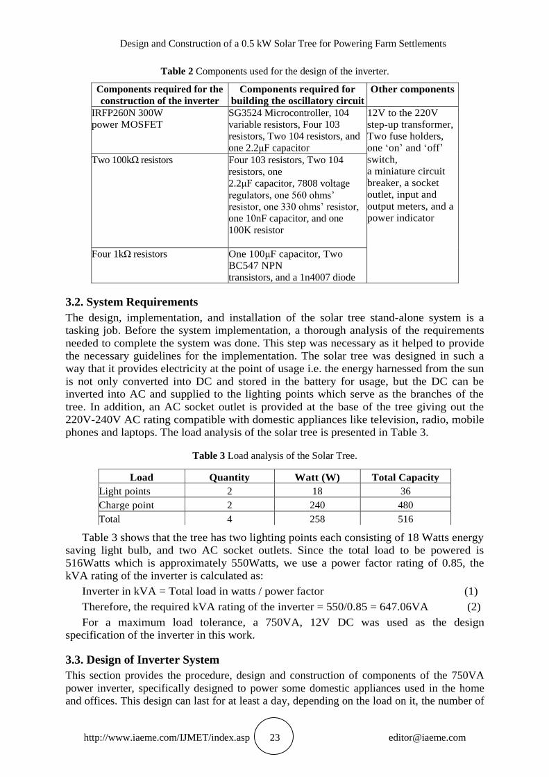
used in this design are also taken into consideration. The block diagram of the power
inverter is shown in Fig. 2.
Figure 2 Block diagram of the Inverter system.
The output gave different waveforms. To give a better output waveform, a modified
sine wave inverter was built to achieve more flexibility in loads it can carry. A 12V/220V
750VA inverter was chosen. The inverter has a dual mode of operation which are the
solar panel and battery mode. An inverter not only converts the DC voltage of the battery
to 220V/240V AC signals but also charges the battery when the solar panel is present and
ready to use. In the solar panel mode, when the solar panel is present and is within the
valid range, the relay between input DC and the inverter output is closed and the input
DC directly goes to the output load. The 12V DC supply from the solar panel is used to
charge the battery.
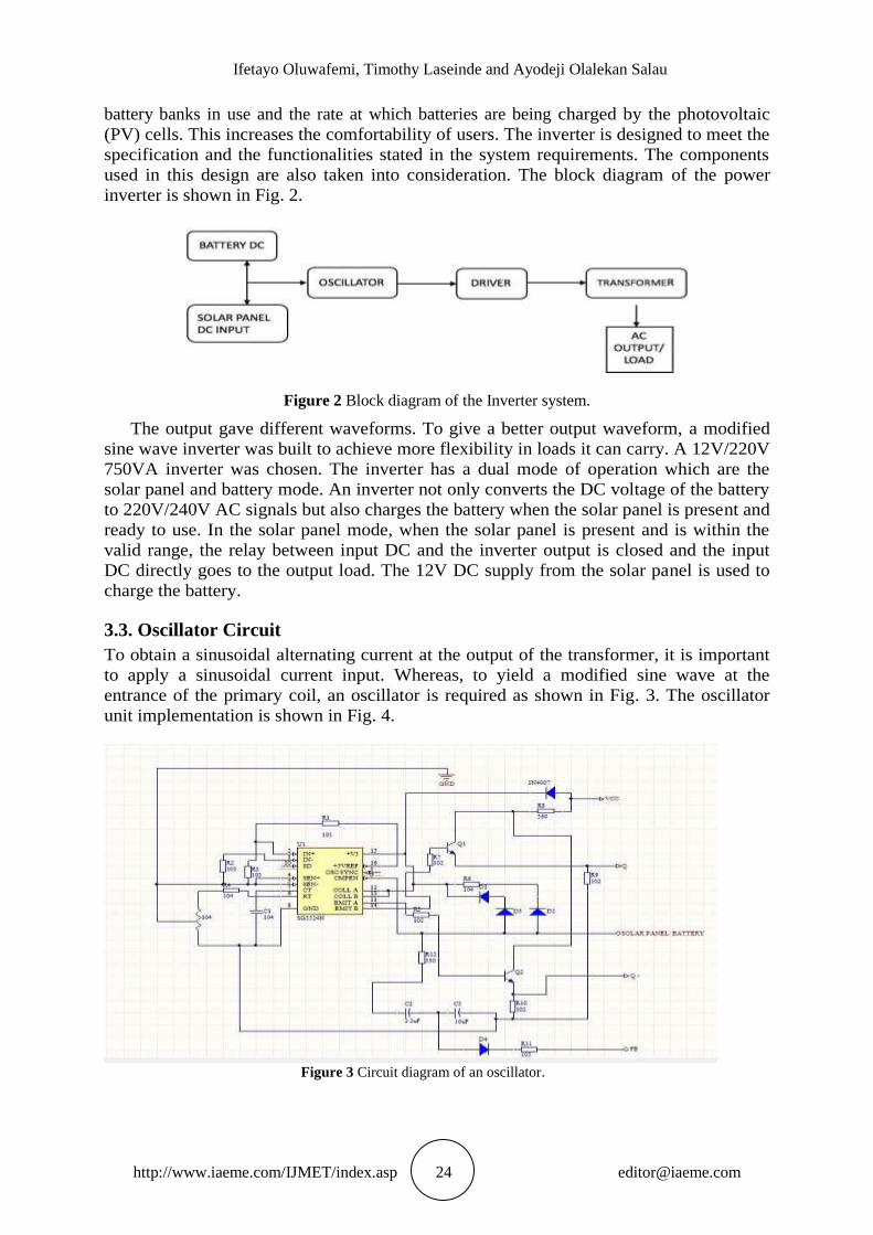
3.3. Oscillator Circuit
To obtain a sinusoidal alternating current at the output of the transformer, it is important
to apply a sinusoidal current input. Whereas, to yield a modified sine wave at the
entrance of the primary coil, an oscillator is required as shown in Fig. 3. The oscillator
unit implementation is shown in Fig. 4.
Figure 3 Circuit diagram of an oscillator.

Design and Construction of a 0.5 kW Solar Tree for Powering Farm Settlements
http://www.iaeme.com/IJMET/index.asp 25 [email protected]
Figure 4 Oscillator circuit.
From the circuit in Fig. 3, resistor R4 (100K) and capacitor C1 (100μF) are the
oscillator timing components. Therefore, frequency (F) can be calculated as:
(2) (3)
Therefore,
= (4)
To get the frequency on each PIN ON, divide by two since R4 and C1 are connected to two separate
pins. Therefore, the system frequency is given as:
(5)
3.4. Driver Circuit
The driver circuit comprises of a switching circuit made of a 1st switching component
and a 2nd switching component linked in series, which are switched on and off in
harmonizing with one another [18]. As shown in Fig. 5, Q1 and Q2 make up the first
switching elements, while Q2 and Q4 make up the second switching elements,
respectively.
Figure 5 Circuit diagram of the driver.

Ifetayo Oluwafemi, Timothy Laseinde and Ayodeji Olalekan Salau
http://www.iaeme.com/IJMET/index.asp 26 [email protected]
3.5. Inverter Transformer Circuit
In this study, the transformer adopted has a center-tapping characteristic which divides
the primary side into two. The center-tapping is directly linked to the positive port of the
battery [19]. Two tops of the primary side are directly linked to the drain of the MOSFET
in the driver circuit. This generates current in the principal coil of the transformer. The
output of the secondary side is a square wave of frequency 50Hz at a voltage of about
220V. The circuit diagram of the transformer unit is shown in Fig. 6.
Figure 6 Circuit diagram of a transformer.
3.6. Design of Charge Controller
This is an important part of the overall system. It monitors the amount of current passing
through the solar panel to the battery. This prevents overcharging of the battery. After a
detailed study, a charge controller with MPPT mechanism was chosen to ensure that there
is an appropriate load impedance matching between the system and the panels.
Two charge controllers were used for this project and the circuit diagram was designed
using Proteus as shown in Fig. 7. The implementation of the charge controller is shown in
Fig. 8.
Figure 7 Circuit diagram of the charge controller.

Design and Construction of a 0.5 kW Solar Tree for Powering Farm Settlements
http://www.iaeme.com/IJMET/index.asp 27 [email protected]
Figure 8 Circuit diagram of a buck converter charge controller.
3.7. Design Calculation and Photovoltaic Module Specifications
The design of the 750VA Solar Tree System followed some validated theories of
operation and meticulous calculations. These theories, procedures, and calculations are
described with respect to the system components in the proceeding sections.
3.8. Solar Module (Panel) Specification
The challenge in the design of a PV-inverter system is to first determine the required type
of solar panels and how to connect them to meet power requirement. Considering the
efficiency and the cost of the different solar modules in the market, the monocrystalline
type was found to be the most appropriate. One panel was used in the analysis of this
system. The PV modules normally come complete without any need for further
improvement aside from maintenance like regular cleaning. It is therefore important to
make a right choice of the rating of the PV panel and then adjust or analyze the system to
suit this choice. For this work, the 100Watts/12V panel was chosen. Based on the
capacity of the system, the total capacity of the PV module/panel needed to effectively
charge the battery was calculated based on these factors, namely:
Daily load requirement.
The average daily peak sun hours.
The efficiency of the PV modules.
3.9. PV Array Mount
In the design phase of this work, we used a pole-mounted procedure to ensure maximum
exposure of the PV modules to sunlight. The solar panel was placed on an iron plate
making an angle with an iron rod which supports it. The panel is placed adequately in
such a way that the panel can move freely to follow the movement of the sun. This
arrangement also makes the panel to possess a very key feature of cooling due to free
passage of air.

Ifetayo Oluwafemi, Timothy Laseinde and Ayodeji Olalekan Salau
http://www.iaeme.com/IJMET/index.asp 28 [email protected]
3.10. Battery Selection
Battery systems are of different types. The most commonly used for inverter applications
are the lead-acid batteries. Due to the high cost of batteries in the market presently, we
have only used a single battery in this work. Solar systems are installed in open
atmospheres exposing the batteries to extreme temperatures. This lead to the construction of a
solid base system which protects the battery and inverter from such extreme conditions. Lead
acid batteries fail in such extreme conditions due to sulphation, and corrosion. Therefore, the
MERCURY VRLA battery was used. Considering the load requirements, a 12V 100AH
battery was used as shown in Fig. 9.
Figure 9 12V 100AH/20HR Mercury rechargeable battery.
3.11. Design of Solar Tracking Circuit
The solar tracking circuit was designed in a way to maximally withdraw power from the solar
panels. The higher the concentration of sunlight that falls on the solar panel, the better the
output performance of the solar panel. Sun tracking is a technique which interchanges solar
panels in different directions in accordance with the intensity of the sun to withdraw extreme
power from the installed solar panels. There are two popular methods of tracking the sun,
namely: Sun solar tracking system and Time solar tracking system [20].
The sun solar tracking structure was implemented for this study, in which the solar
panel is rotated with the support of a motor directed to the path of sunlight. This was
done to ensure the solar panel is subjected to extreme sunlight, since the greater the
sunlight, the greater the output of the solar panel. Due to the size and weight of the solar
panel, a linear actuator was used instead of using several stepper motors to rotate the
solar panel in the direction of sunlight. Part of the components that make up the solar
tracking circuit are:
Two Light dependent resistors (LDR)
24 inches 36VDC linear actuator
Arduino Nano microcontroller
Four relays
Four lights emitting diodes (LED)
Four automatic voltage regulators.

Design and Construction of a 0.5 kW Solar Tree for Powering Farm Settlements
http://www.iaeme.com/IJMET/index.asp 29 [email protected]
3.12. Operating Mechanism of the Solar Tracking Circuit
The solar tracking circuit was designed with two light dependent resistors (LDRs), each
placed at either side of the panel. The two LDRs are connected to the analog pins of the
Arduino. They send signals to the Arduino and these generated signals produce an output
based on the program code. The output is sent to the digital pins. The digital pins are
connected to the base of the NPN transistor which feeds the coil and triggers the relay to
power the linear actuator.
Figure 10 Solar tracking circuit.
3.13. Design of Solar Tree Frame Work
This section shows the detailed design of the solar tree framework. The framework was
designed to make the project simple and have a total weight of approximately 120kg.
This was done by careful selection of materials used in the construction. The system was
designed with the aid of AutoCAD software.
As shown in Fig. 11 and Fig. 12, the solar tree has its panels mounted on a hollow
pole which is made of steel. The panel is placed on a metal frame which sits on the
hollow pole. A box-like metal frame compartment was constructed between the pole and
the panel as shown in Fig. 11. This compartment is made for the solar tracking circuit.
The hollow pole is used to conceal the connecting wires running from the panel and the
solar tracking circuit to the base of the tree. The base of the tree is a box made up of a
metal frame for rigidity and a wooden finishing. The base compartment is where the
inverter and battery are placed. The hollow pole is attached to the base by screwing it to
make the mobility of the base compartment easy. The tree has two branches as shown in
the Figs. 11and 12. These branches serve as the frame for the lighting points.
Figure 11. Solar tree framework design without the panel.

Ifetayo Oluwafemi, Timothy Laseinde and Ayodeji Olalekan Salau
http://www.iaeme.com/IJMET/index.asp 30 [email protected]
Figure 12 Solar tree framework with solar panel mounted on top.
4. RESULTS AND DISCUSSION
4.1. Analysis of the Solar Tree Design
The construction of the solar tree was broken down into various sections, namely: the solar
panel selection, the design and construction of the inverter, the battery selection, solar
tracking circuit construction, and framework construction. During the construction
process, various analysis and decisions were made to ensure that the aim and objectives
of this work were met.
4.2. Inverters Solar Panel Testing and Analysis
From Table 4, it is seen that the actual voltage readings deviated marginally from the
expected (standard) values. In testing the performance of the panel with respect to its
environment, many considerations were made to select test equipment. A multimeter was
used to measure the output values and a 2m high steel pole was used for mounting, one
18Watt energy saving light bulb, a mobile phone, and a laptop which was used for loading
purposes. The versatility of the panel to effectively power a wide range of domestic devices
solely stands on its ability to withstand the likely environmental conditions. This was
achieved with the series of tests carried out on it.
Table 4 Test results of PV panel and Inverter under different environmental conditions.
Conditions Output DC (V)
from Solar Panel
Output AC (V)
from Inverter
Expected DC (V)
Output
from Solar Panel
Expected AC
(V) Output
from Inverter
Test under a very
sunny and bright day
21.2 167 24 210
Test under a cloudy
and breezy day
8.6 96 10.4 98
Test under a rainy
day
3.7 23 4.3 41
Test under dusty and
dirty environmental
conditions
18.5 154 20 180

Design and Construction of a 0.5 kW Solar Tree for Powering Farm Settlements
http://www.iaeme.com/IJMET/index.asp 31 [email protected]
Test under dusty and
dirty environmental
conditions
12.2 105 14 132
Test under a very
humid at-
atmospheric
condition.
15.2 113 18 163
4.3. Battery Voltage Observation
The expected battery bank voltage from the analysis is 12V, the actual voltage obtained from
measurement is 14.2V. This discrepancy is because the batteries are generally made to have a
voltage slightly above their estimated voltage (in this case 12V). This is to help accommodate
for the gradual voltage depletion that normally takes place when the batteries are not in use.
This ensures that whenever the battery is loaded, the output voltage would be above 12V.
4.4. Performance Evaluation
Here, several tests of the connection of the components or constructions during each stage of
the power inverter design and construction were carried out. Also, several tests were carried
out after each module of the converter.
These tests carried out include:
Oscillator testing
Driver testing
Transformer testing
Testing of output waveform.
4.4.1. Oscillator testing
The oscillator was tested by placing the negative probe of the multimeter on the negative
terminal (the ground) of the oscillator circuit which is coupled to the negative port of 12V
battery, while the positive probe of the multimeter is placed on the junction of the emitter
of the NPN, BC547 transistor (Q or Q-) of the oscillator circuit. The output voltage was
4V and this indicates that the oscillator circuit is in standard operating condition.
4.4.2. Driver testing
The test carried out on the driver circuit was impedance testing. The negative probe of the
meter was connected to the drain of the MOSFET and the positive probe of the meter was
connected to the source of the MOSFET which is connected to the negative terminal of
the battery. The reading was 350Ω. This value indicates that the driver circuit is working
in standard operating condition.
4.4.3. Transformer testing
Continuity tests were carried out on the primary and secondary windings to check for the
continuity of each winding. The test was carried out by means of a continuity circuit
tester. The constructed transformer was a 12V-220V step-up center tap transformer. All
windings and terminals were continuous when they were tested.
In additiion, 12V was applied to the primary side and 242V was obtained at the
secondary side of the transformer, thus confirming a step-up voltage transformation.
4.4.4. Output waveform
Another important test carried out during the construction of the power inverter was the
output waveform test. The output from the oscillator, driver stage (MOSFET) and the

Ifetayo Oluwafemi, Timothy Laseinde and Ayodeji Olalekan Salau
http://www.iaeme.com/IJMET/index.asp 32 [email protected]
transformer produce a modified sine wave. This is as a result of the stable mode of the
oscillator. This waveform was detected using an oscilloscope set at a frequency of 50Hz.
5. CONCLUSION AND RECOMMENDATIONS
In this study, we have designed and constructed a Solar Tree system to produce
electricity which is environmentally friendly and which can be used as a source of power
for agricultural, household and commercial purposes.
During the design and construction of this system, a lot of theories were put into
practice, a few challenges, constraints, and limitations were encountered, and various
techniques and methods were implemented to overcome the challenges so as to meet the
desired goal of this study.
These challenges were carefully resolved without hindering the goal of the study, which is
to economically generate power using solar energy. Some of the major challenges
encountered are listed so that researchers can further improve on the system based on the
observations we made.
The high implementation cost of the project. This is due to the global low-efficiency
limitation still faced in solar panel technology, the number of panels needed to generate
up to 1KW which is enormous. This made the developed system to be scaled down to a
total capacity of about 800W.
The size of the panel made the constructed framework support to be heavier than the
proposed weight of the system. This added to the overall complexity of the system and
limited the mobility of the system. Maximum energy generation from solar power is only
possible when the light intensity falling on the panel from the sun is high. This implies that
large storage energy systems are needed to cater for days with poor weather conditions.
REFERENCES
[1] E. A. Umoh and A. A. Luggage, “Contextualizing hazard mitigation policy for
electricity grids in the Sudan Sahel Region of Nigeria,” Energy Policy, vol. 124, pp.
135–43, 2019.
[2] M. O. Oseni, “Self-Generation and Households‟ Willingness to Pay for Reliable
Electricity Service in Nigeria,” Energy Journal, vol. 38, no. 4, pp. 94-165, 2017.
[3] K. M. Powell, K. Rashid, K. Ellingwood, J. Tuttle, and B. D. Iverson, “Hybrid
concentrated solar thermal power systems: a review,” Renewable and Sustainable
Energy Reviews, pp. 215–37, 2017.
[4] A. K. Akella and S. Das, “Technical and Socio-Economic Aspects of Hybrid
Renewable Energy Sources: A Step-by-Step Approach,” International Journal of
Applied Engineering Research, vol. 12, no. 21, pp. 11228-11241, 2017.
[5] S. C. Wind and Waves, and the Sun: The Rise of Alternative Energy. Cavendish
Square Publishing, LLC, 2017.
[6] S. Obasi, “75% Nigerians lack access to regular power,” 2015. [Online]. Available:
https://www.vanguardngr.com/2015/ 11/75-nigerians-lack-access-to-regular-power/.
[7] N. S. Ouedraogo, “Modeling sustainable long-term electricity supply-demand in
Africa,” Applied energy, pp. 1047–67, 2017.
[8] S. Gupta and M. Gupta, “The benefits and applications of the solar tree with the
natural beauty of Trees,” SSRG International Journal of Electrical and Electronics
Engineering, pp. 29-34, 2015.
[9] W. Cao, Z. Li, Y. Yang, Y. Zheng, W. Yu, R. Afzal and J. Xue, “Solar tree: Exploring
new form factors of organic solar cells,” Renewable energy, pp. 134–9, 2014.
Design and Construction of a 0.5 kW Solar Tree for Powering Farm Settlements
http://www.iaeme.com/IJMET/index.asp 33 [email protected]
[10] R. Lamb, Analysis of net-zero energy homes and net-zero energy communities in hot and
humid climates from the builder‟s perspective, The University of Florida (Doctoral
dissertation), pp. 1-108, 2009.
[11] P. S. Ubi, L. Effiom, and E. O. Okon, A. E. Oduneka, “An econometric analysis of the
determinants of electricity supply in Nigeria,” International Journal of Business
Administration, vol. 3, no. 4, p. 72-82, 2012.
[12] A. S. Sambo, “Matching electricity supply with demand in Nigeria,” International
Association of Energy Economics, vol. 4, pp. 32–38, 2009.
[13] V. Okolobah and Z. Ismail, “On the issues, challenges, and prospects of electrical power sector in
Nigeria,” International Journal of Economy, Management and Social Sciences, vol. 2, no.
6, pp. 410-418, 2013.
[14] A. S. Sambo, “Renewable energy development in Nigeria,” Workshop on Renewable
Energy, Accra, Ghana, pp. 1-39, 2010.
[15] W. A. Isola and L. O. Oderinde, “Interfuel substitution and allocative efficiency in
electricity production in Nigeria,” Journal of Business, pp. 1-21, 2010.
[16] B. Floyd, “Eastern, Nigeria: a geographical review,” Springer, p. 345, 1969.
[17] O. I. Okoro and E. Chikuni, “Power sector reforms in Nigeria: opportunities and
challenges,” Journal of Energy in Southern Africa, vol. 18, no. 3, pp. 52-57, 2007.
[18] T. Ichihara, “Driver Circuit for Inverter,” 1997. Available online:
http://www.freepatentsonline.com/5684687.html
[19] O. O. Omitola, S. O. Olatinwo, T. R. Oyedare, “Design and construction of 1KW
(1000VA) power inverter,” Innovative Systems Design and Engineering, vol. 5, no. 2, pp.
1-13, 2014.
[20] C. Yang, T. Cheng, C. Cheng, and C. W. C. Lee, “Open-loop altitude-azimuth
concentrated solar tracking system for solar thermal applications,” Solar Energy, vol. 147,
pp. 52–60, 2017.