design and analysis of an in-pipe inspection robot
TRANSCRIPT
International Journal of Scientific Research and Engineering Development-– Volume 4 Issue 2, Mar- Apr 2021
Available at www.ijsred.com
ISSN : 2581-7175 ©IJSRED: All Rights are Reserved Page 837
Design and Analysis of an in-Pipe Inspection Robot Deepak Sonawane
1, Samadhan Bhosle
2, Omkar Baile
3, Omswarup Kotkar
4
New Horizon Institute of Technology & Management (Thane), Mumbai University
Umesh Solase5, Asst. Prof. New Horizon Institute of Technology & Management, Thane..
Abstract:-
Previously there are various designs available regarding of
an in-pipe inspection robot. This research paper aims at
preparing a new design along with its Analysis. In a
beginning we studied the available designs and Analysis
reports. We have used SOLIDWORKS to design and
Analysis of our robot. Our model is a wireless in-pipe
inspection robot which is efficient to pass through hapipe
with diameter in rangeof170-200mm.The important areas
we have considered while in the process of design are
strength, safety while performing task, steer ability, and the
most important one is size and shape adjustability We can
detect various defects such as cracks, corrosion, blockages,
material decay, flaws etc.
Index Terms: in- pipe-inspection,strength, shape
adjustability, wireless,Design, Analysis.
INTRODUCTION
Robotics is one of the fastest growing engineering fields of
today. Robots are designed to remove the human factor from
labor intensive work. The main concept behind the making of
an in-pipe inspection robot is to lower the cost of labour and
increase safety and accuracy in inspection.We did design and
analysis of robot considering the complexity in pipes used
invarious power plants. Our robot can adapt itself according
to the varying pipe diameter ranging from 170-200mm. The
oil, steam and water distribution pipelines as well as heavy
industrial plants require routine inspection. We have used
single joint locomotive system so that our robot can pas
through horizontal and incline pipes. The microcontroller is
used for making robot fully autonomous. The Wireless
camera is mounted at the front side of the assembly which can
cover front area of the pipe.The result of camera is given
through the receiver connected to LED screen. The range of
camera receiveris approximately 25m while that of the remote
is 8m.
LITERATUREREVIEW
From the research paper of Jong-Hoon Kim, Gokarna
Sharma, and S. Sitharama Iyengar have proposed the design
and implementation of a single module fully autonomous
mobile pipeline exploration robot, called FAMPER that can
be used for the inspection of 150mm pipelines. This robot
consistsof four wall-press caterpillars operated by two DC
motors each.The speedof each caterpillar is controlled
independently to provide steering capability to go through
45-degree elbows, 90-degree elbows, T-branches, and Y
branches. The uniqueness of this paper is to show the
opportunity of using 4 caterpillar configuration of superior
performance in all types of complex networks of pipelines.
The robot system has been developed and experimented in
different pipeline layout. This robot also has wide
applications in chemical industries as well as in gulf
countries for inspection of oil and gas pipelines[1].From
there search paper of Atul Gargade1, Dhanraj
Tambuskar,Gajanan Thokal have proposed that robot consists
of a foreleg system, a rear leg system, and a body. The fore
and rear leg systems are constructed by using three worm
gear system that is arranged at an angle of 120 degrees with
respect to each other to operate inside a pipe of different
diameters. The springs are attached to each leg and the robot
body to operate in pipes of 140mm to 200mm diameter
range. [2]The research paper of palwinder Kaur1, Ravinder
Kaur, Gurpreet Singh have worked on innovative concept to
handle the bore well rescue operations without human
intervention and to inspect any type of leakage in the pipe.
Wheeled leg mechanism is employed in this design to go
inside the pipe. The legs are circumferentially and
symmetrically spaced out 120º apart. The robot is made
adaptive so that it can adjust its legs according to the pipeline
dimensions. This structural design makes it possible to have
the adaptation to the diameter of the pipe and to have
adjustable attractive force towards the walls of the
pipe.[3]Nur Afiqah Binti Haji Yahya, Negin Ashrafi, Ali
Hussein Humod have explained the robotics application in
various industries mainly in pipeline inspection. This review
paper was to fulfill the requirement of Automation and
Robotics module assessment. The objectives of this review
paper are; to observe different robotics applications in
pipelines inspection, to learn the different design of robots in
pipeline inspection, to outline the problems and adaptability
improvements in the robotics application that was applied. At
the end of this review paper, it was concluded that
improvements were seen in few designs of the robot example
like the Parallelogram Wheel Leg [4].proposes a hybrid
locomotion system for inspection. The research paper of Xin
Li [5], proposes guarding algorithm along with optimal
guarding algorithm.
RESEARCH ARTICLE OPEN ACCESS
International Journal of Scientific Research and Engineering Development
ISSN : 2581-7175 ©IJSRED: All Rights are
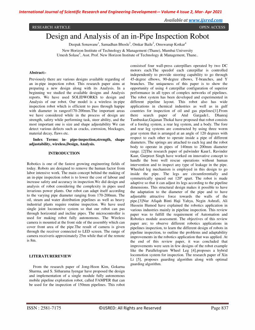
Mechanism
Fig.1-Mechanism
Designs
A.Motor
Total load on robot = 50N (approx.)
Power required to robot to carry weight of 50N with 0.1m/s
speed is,
P = W × v
P = 50 × 0.1
P = 5 watts.
In worst case if only one motor is working then
totalpower.Powerrequiredto3-DCmotorstodrivetherobot is,
Prequired = 5*2
Prequired =10 watts
If a motor of 12V&1amp current is selected then power provided
by 3 motors is,
Pprovided = 30watts
Here, Pprovided>Prequired .................. Henceok. So, select 3-DC motors of 12v, 1amp current.
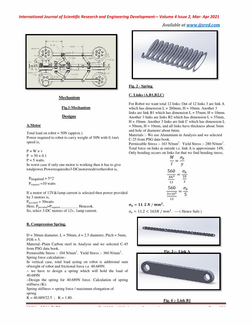
B. Compression Spring.
D = 30mm diameter, L = 50mm, d = 2.5 diameter, Pitch = 5mm,
FOS = 5.
Material:-Plain Carbon steel in Analysis and we selected
from PSG data book.
Permissible Stress :- 104 N/mm2. Yield Stress
Spring force calculation:-
In vertical case, total load acting on robot is additional sum
ofweight of robot and frictional force i.e. 40.689
∴ we have to design a spring which will hold the load of
40.689N
∴Design the spring for 40.689N force. Calculation of spring
stiffness (K):
Spring stiffness = spring force / maximum elongation of
spring
K = 40.689/22.5 ; K = 1.80.
International Journal of Scientific Research and Engineering Development-– Volume 4 Issue 2, Mar
Available at www.ijsred.com
©IJSRED: All Rights are Reserved
N with 0.1m/s
In worst case if only one motor is working then it has to give
DCmotorstodrivetherobot is,
amp current is selected then power provided
D = 30mm diameter, L = 50mm, d = 2.5 diameter, Pitch = 5mm,
in Analysis and we selected C-45
:- 360 N/mm2.
In vertical case, total load acting on robot is additional sum
40.689N.
we have to design a spring which will hold the load of
Calculation of spring
Spring stiffness = spring force / maximum elongation of
Fig. 2 - Spring
C. Links (A,B1,B2,C)
For Robot we want total 12 links. Out of 12 links 3
which has dimension L = 260mm, H = 10mm. Another 3
links are link B1 which has dimension L = 55mm, H = 10mm.
Another 3 links are links B2 which has dimension L = 55mm,
H = 10mm. Another 3 links are link C which has dimension L
= 50mm, H = 10mm, and all links have thickness about 3mm
and hole of diameter about 6mm.
Materials :- We use Aluminium in Analysis and we selected
C-25 from PSG data book.
Permissible Stress :- 163 N/mm2. Yield Stress :
Total force on links at outside i.e. link
Only bending occurs on links for that we find bending stress,
�
����
�
560
��
��
�����
�
560
����
��
���
5
�� � ��. �� ����.
�� � 11.2 � 163� � �. ----( Hence Safe.)
Fig. 3 :– Link A
Fig. 4 :- Link B1
Volume 4 Issue 2, Mar- Apr 2021
www.ijsred.com
Page 838
For Robot we want total 12 links. Out of 12 links 3 are link A
which has dimension L = 260mm, H = 10mm. Another 3
links are link B1 which has dimension L = 55mm, H = 10mm.
Another 3 links are links B2 which has dimension L = 55mm,
H = 10mm. Another 3 links are link C which has dimension L
and all links have thickness about 3mm
We use Aluminium in Analysis and we selected
. Yield Stress :- 280 N/mm2.
A is approximate 14N.
Only bending occurs on links for that we find bending stress,
( Hence Safe.)
Link A
Link B1

International Journal of Scientific Research and Engineering Development
Fig. 5 :- Link B2
Fig. 6 :- Link C
D. Translation Element
We have dimensions L = 40mm and H = 30mm diameter, Inner
diameter = 25mm diameter, Extended portion from center of
translation element and they have hole of 6mm diameter.
translationelementwe use Aluminium in analysis
As we know the force on spring from outside is around 42N. So
the same force is applied on translation element and then on
spring.
Fig. 7 :- Translation element
E. Central Frame
We have dimensions Total L = 300mm, H = 25mm diameter,
and inner diameter = 17mm, Thickness of Extended Part=8mm.
Material use for this component is Aluminium in Analysis.
are total 6 extended parts on Center Frame 3 on 70mm from one
end and another 3 on 170mm from one end and the have hole of
diameter 6mm.
International Journal of Scientific Research and Engineering Development-– Volume 4 Issue 2, Mar
Available at www.ijsred.com
dimensions L = 40mm and H = 30mm diameter, Inner
diameter = 25mm diameter, Extended portion from center of
translation element and they have hole of 6mm diameter. For
use Aluminium in analysis.
side is around 42N. So
the same force is applied on translation element and then on
Translation element
have dimensions Total L = 300mm, H = 25mm diameter,
and inner diameter = 17mm, Thickness of Extended Part=8mm.
Material use for this component is Aluminium in Analysis.There
are total 6 extended parts on Center Frame 3 on 70mm from one
on 170mm from one end and the have hole of
Fig. 8 :- Center Frame
F. Wheels
We have dimensions Total diameter = 62mm, Thickness =
12mm and at center hole = 6mm diameter.
Material for Wheels we use Aluminium in Analysis.
As we know the total force on link and spring is same and this
force or load is coming from Wheel therefore the force on
wheel will be same. On each wheel 7N force is getting and on
one link there are two wheels is there therefore total 14N on
each link. On the surface of wheels there are many holes and
at center the shaft of motor will be fix. As motor starts
rotating the wheel also gets rotation and Robot starts crawl
under the pipe.
Fig. 9 :- Wheel
G. Rivets
There are total 24 rivets we have to use. Out of which 9 are
link rivets, 6 are wheel rivets, 6 are center frame rivets and 3
are translation element rivets.
Dimensions we have L = 10mm, 19mm, 15mm, 18mm and H
= 10mm diameter for all rivets.
We use material for Rivets is Aluminium in Analysis and we
selected C-20 from PSG data book.
On rivets there are only shear stress acting. Therefore we have
find shear value for that
Shear stress = !�"#$%&'()$*"
+$"#
, �14
.
/� 6�
, � 0.495�/ 2.
We have Permissible stress = 160 N/mm
And FOS = 3.
Volume 4 Issue 2, Mar- Apr 2021
www.ijsred.com
have dimensions Total diameter = 62mm, Thickness =
12mm and at center hole = 6mm diameter.
Material for Wheels we use Aluminium in Analysis.
e total force on link and spring is same and this
force or load is coming from Wheel therefore the force on
wheel will be same. On each wheel 7N force is getting and on
one link there are two wheels is there therefore total 14N on
of wheels there are many holes and
at center the shaft of motor will be fix. As motor starts
rotating the wheel also gets rotation and Robot starts crawl
There are total 24 rivets we have to use. Out of which 9 are
6 are center frame rivets and 3
Dimensions we have L = 10mm, 19mm, 15mm, 18mm and H
material for Rivets is Aluminium in Analysis and we
acting. Therefore we have
We have Permissible stress = 160 N/mm2.
International Journal of Scientific Research and Engineering Development
ISSN : 2581-7175 ©IJSRED: All Rights are
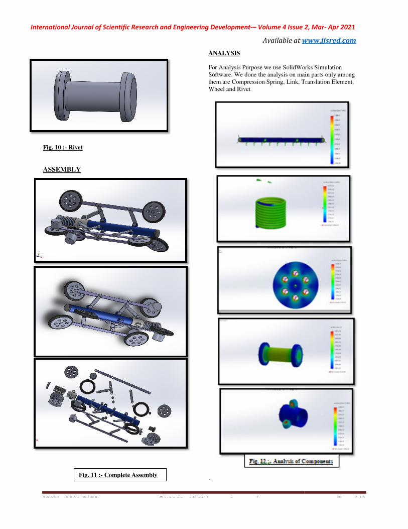
Fig. 10 :- Rivet
ASSEMBLY
Fig. 11 :- Complete Assembly
International Journal of Scientific Research and Engineering Development-– Volume 4 Issue 2, Mar
Available at www.ijsred.com
©IJSRED: All Rights are Reserved
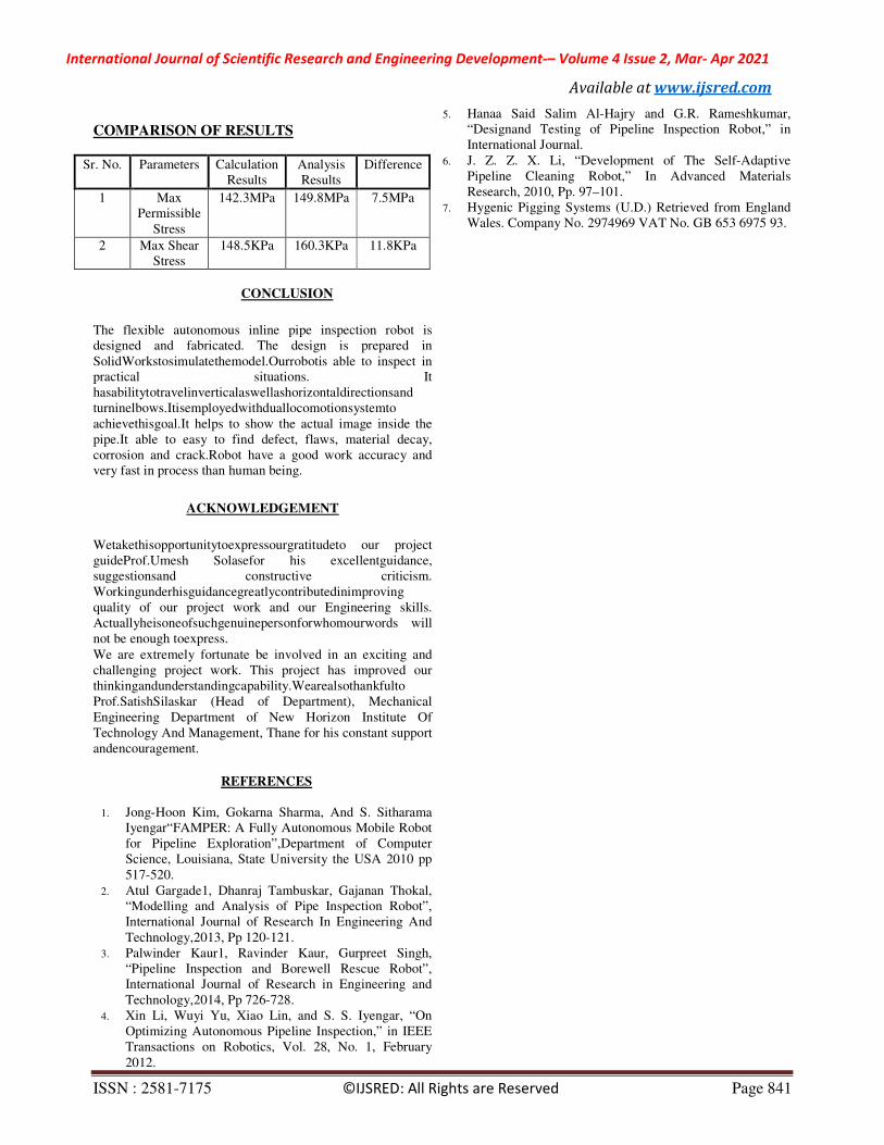
ANALYSIS
For Analysis Purpose we use SolidWorks Simulation
Software. We done the analysis on main parts only among
them are Compression Spring, Link, Translation Element
Wheel and Rivet
.
Volume 4 Issue 2, Mar- Apr 2021
www.ijsred.com
Page 840
For Analysis Purpose we use SolidWorks Simulation
Software. We done the analysis on main parts only among
Spring, Link, Translation Element,
International Journal of Scientific Research and Engineering Development-– Volume 4 Issue 2, Mar- Apr 2021
Available at www.ijsred.com
ISSN : 2581-7175 ©IJSRED: All Rights are Reserved Page 841
COMPARISON OF RESULTS
Sr. No. Parameters Calculation
Results
Analysis
Results
Difference
1 Max
Permissible
Stress
142.3MPa 149.8MPa 7.5MPa
2 Max Shear
Stress
148.5KPa 160.3KPa 11.8KPa
CONCLUSION
The flexible autonomous inline pipe inspection robot is
designed and fabricated. The design is prepared in
SolidWorkstosimulatethemodel.Ourrobotis able to inspect in
practical situations. It
hasabilitytotravelinverticalaswellashorizontaldirectionsand
turninelbows.Itisemployedwithduallocomotionsystemto
achievethisgoal.It helps to show the actual image inside the
pipe.It able to easy to find defect, flaws, material decay,
corrosion and crack.Robot have a good work accuracy and
very fast in process than human being.
ACKNOWLEDGEMENT
Wetakethisopportunitytoexpressourgratitudeto our project
guideProf.Umesh Solasefor his excellentguidance,
suggestionsand constructive criticism.
Workingunderhisguidancegreatlycontributedinimproving
quality of our project work and our Engineering skills.
Actuallyheisoneofsuchgenuinepersonforwhomourwords will
not be enough toexpress.
We are extremely fortunate be involved in an exciting and
challenging project work. This project has improved our
thinkingandunderstandingcapability.Wearealsothankfulto
Prof.SatishSilaskar (Head of Department), Mechanical
Engineering Department of New Horizon Institute Of
Technology And Management, Thane for his constant support
andencouragement.
REFERENCES
1. Jong-Hoon Kim, Gokarna Sharma, And S. Sitharama
Iyengar“FAMPER: A Fully Autonomous Mobile Robot
for Pipeline Exploration”,Department of Computer
Science, Louisiana, State University the USA 2010 pp
517-520.
2. Atul Gargade1, Dhanraj Tambuskar, Gajanan Thokal,
“Modelling and Analysis of Pipe Inspection Robot”,
International Journal of Research In Engineering And
Technology,2013, Pp 120-121.
3. Palwinder Kaur1, Ravinder Kaur, Gurpreet Singh,
“Pipeline Inspection and Borewell Rescue Robot”,
International Journal of Research in Engineering and
Technology,2014, Pp 726-728.
4. Xin Li, Wuyi Yu, Xiao Lin, and S. S. Iyengar, “On
Optimizing Autonomous Pipeline Inspection,” in IEEE
Transactions on Robotics, Vol. 28, No. 1, February
2012.
5. Hanaa Said Salim Al-Hajry and G.R. Rameshkumar,
“Designand Testing of Pipeline Inspection Robot,” in
International Journal.
6. J. Z. Z. X. Li, “Development of The Self-Adaptive
Pipeline Cleaning Robot,” In Advanced Materials
Research, 2010, Pp. 97–101.
7. Hygenic Pigging Systems (U.D.) Retrieved from England
Wales. Company No. 2974969 VAT No. GB 653 6975 93.

International Journal of Scientific Research and Engineering Development
ISSN : 2581-7175 ©IJSRED: All Rights are
DeepakSonawane Studying in B.E Mechanical Engineering
in New Horizon Institute of Technology
Management, Thane
.
Samadhan BhosleStudying in B.E Mechanical Engineering
in New Horizon Institute of Technology and Management,
Thane.
OmkarBaileStudying in B.E Mechanical Engineering in New
Horizon Institute of Technology and Management, Thane.
OmswarupKotkar Studying in B.E Mechanical
Engineering in New Horizon Institute of Technology
Management, Thane
International Journal of Scientific Research and Engineering Development-– Volume 4 Issue 2, Mar
Available at www.ijsred.com
©IJSRED: All Rights are Reserved
Studying in B.E Mechanical Engineering
in New Horizon Institute of Technology and
Studying in B.E Mechanical Engineering
nd Management,
Studying in B.E Mechanical Engineering in New
nd Management, Thane.
Studying in B.E Mechanical
Engineering in New Horizon Institute of Technology and
Volume 4 Issue 2, Mar- Apr 2021
www.ijsred.com
Page 842