design and analysis of a condenser in a refrigerator …
TRANSCRIPT

Volume 03, Issue 11, Nov 2019 ISSN 2581 – 4575 Page 1
DESIGN AND ANALYSIS OF A CONDENSER IN A REFRIGERATOR
USING DIFFERANT REFRIGERANTS 1
SHAIK AMAR BASHA, 2M.KOTAIAH,
3L. VIJAY
1Department of mechanical engineering M-Tech student (CAD/CAM) in Eswar College of Engineering
Kesanupalli Village, Narasaraopet, Andhra Pradesh 522601 2Department of mechanical engineering Assistant Professor (CAD/CAM) in Eswar College of Engineering
Kesanupalli Village, Narasaraopet, Andhra Pradesh 522601 3Department of mechanical engineering Assistant Professor (CAD/CAM) in Eswar College of Engineering
Kesanupalli Village, Narasaraopet, Andhra Pradesh 522601
ABSTRACT
A condenser is designed to transfer heat from a working fluid (e.g. water in a steam power
plant) to a secondary fluid or the surrounding air. The condenser relies on the efficient heat
transfer that occurs during phase changes, in this case during the condensation of a vapor into a
liquid.The materials considered for tubes are Copper and Aluminium alloys 1060 and 1100. The
refrigerants varying will be R 12, R22 and R407C. CFD analysis is done to determine
temperature distribution and heat transfer rates by varying the refrigerants. Heat transfer analysis
is done on the condenser to evaluate the better material.In this project thermal analysis to
determine the temperature distribution and heat flux at different materials of condenser (copper
and aluminium alloys), CFD analysis to determine the pressure drop, velocity, heat transfer
coefficient, mass flow rate and heat transfer rate at different refrigerants of the condenser.
In this thesis the condenser model designing in CREO and analysis in ANSYS software.
INTRODUCTION
The Refrigeration Cycle The refrigerator in
your kitchen uses a cycle that is similar to
the one described in the previous section.
But in your refrigerator, the cycle is
continuous. This is what happens to keep the
refrigerator cool: Butane Lighters If you go
to the local store and buy a disposable
butane lighter with a clear case (so that you
can see the liquid butane inside), what you
are seeing is liquid butane stored in a high-
pressure container. Butane boils at 31
degrees F at normal atmospheric pressure
(14.7 PSI).
Freon® breaks down ozone into oxygen gas.
The reaction is shown below. As of the
1990s, all new refrigerators and air
conditioners use refrigerants that are less
harmful to the ozone layer.
Use of highly purified liquified propane gas
as a refrigerant is gaining favor, especially
in systems originally designed for Freon®.

Volume 03, Issue 11, Nov 2019 ISSN 2581 – 4575 Page 2
Yes, the same liquid used in barbeque grills.
As such, it is designated as R-290 and is
marketed under the trade name Duracool®.
Although propane is flammable, in home
and automotive systems it is present in
quantities small enough to not pose an
undue fire hazard if a system should develop
a leak. Moreover, propane is nontoxic.
1. Air-cooled condensers:
As the name implies, in air-cooled
condensers air is the external fluid, i.e., the
refrigerant rejects heat to air flowing over
the condenser. Air-cooled condensers can be
further classified into natural convection
type or forced convection type.
Natural convection type:
In natural convection type, heat transfer
from the condenser is by buoyancy induced
natural convection and radiation. Since the
flow rate of air is small and the radiation
heat transfer is also not very high, the
combined heat transfer coefficient in these
condensers is small. As a result a relatively
large condensing surface is required to reject
a given amount of heat. Hence these
condensers are used for small capacity
refrigeration systems like household
refrigerators and freezers. The natural
convection type condensers are either plate
surface type or finned tube type. In plate
surface type condensers used in small
refrigerators and freezers, the refrigerant
carrying tubes are attached to the outer walls
of the refrigerator. The whole body of the
refrigerator (except the door) acts like a fin.
Insulation is provided between the outer
cover that acts like fin and the inner plastic
cover of the refrigerator. It is for this reason
that outer body of the refrigerator is always
warm. Since the surface is warm, the
problem of moisture condensation on the
walls of the refrigerator does not arise in
these systems. These condensers are
sometimes called as flat back condensers.
1. Evaporative condensers:
In evaporative condensers, both air and
water are used to extract heat from the
condensing refrigerant. Figure above
shows the schematic of an evaporative
condenser. Evaporative condensers
combine the features of a cooling tower
and water-cooled condenser in a single
unit. In these condensers, the water is
sprayed from top part on a bank of tubes
Volume 03, Issue 11, Nov 2019 ISSN 2581 – 4575 Page 3
carrying the refrigerant and air is
induced upwards. There is a thin water
film around the condenser tubes from
which evaporative cooling takes place.
The heat transfer coefficient for
evaporative cooling is very large. Hence,
the refrigeration system can be operated
at low condensing temperatures (about
11 to 13 K above the wet bulb
temperature of air). The water spray
countercurrent to the airflow acts as
cooling tower. The role of air is
primarily to increase the rate of
evaporation of water. The required air
flow rates are in the range of 350 to 500
m3/h per TR of refrigeration capacity.
Function of condenser
The main function of condenser is to convert
gaseous form of exhaust steam into liquid
form at a pressure of below atmosphere.
Cooling medium is used water to convert
steam into water.
Condenser vacuum and air leakage
The pressure inside the condenser is less
than the atmospheric as condensation of
steam reduces its volume. The pressure
below the atmospheric is called vacuum. In
order to obtain the maximum work from unit
mass of steam, the pressure should be as low
as possible. Because of low pressure inside
the condenser, the air infiltrates into the
system so the condenser is always filled
with a mixture of water, steam and air.
Literature review
Chandrashekhar M. Bagade et al (2012)Day
by day there is increasing demand of
refrigerating effect which increases the load
on compressor. But sub cooling and
superheating are the process used for getting
maximum refrigerating effect, ultimately
improve COP of the refrigerating system.
Condenser plays an important role in any
refrigeration system .it is use to remove heat
from refrigerant vapour coming from
compressor p-h and Ts diagrams clearly
shows, the effect of sub cooling after
condensate formation on COP. Now a day
we are interested in improving COP of
refrigeration system, without affecting
compressor work. Sub cooling is one of the
factors that can improve the COP of
refrigeration system. Sub cooling is done in
the condenser, thus condenser design is the
key factor to improve the COP of domestic
refrigeratorPROBLEM DESCRIPTION
The materials considered for tubes are
Copper and Aluminium alloys 1060 and
1100. The refrigerants varying will be R 12,
R22 and R407C. CFD analysis is done to
determine temperature distribution and heat
transfer rates by varying the refrigerants.
Heat transfer analysis is done on the
condenser to evaluate the better material.
In this project thermal analysis to determine
the temperature distribution and heat flux at
different materials of condenser (copper and
aluminium alloys), CFD analysis to
determine the pressure drop, velocity, heat
transfer coefficient, mass flow rate and heat
transfer rate at different refrigerants of the
condenser.
In this thesis the condenser model designing
in CATIA and analysis in ANSYS software.
INTRODUCTION TO CAD
CAD (Computer Aided Design) is the use of
computer software to design and document a
product’s design process.
Engineering drawing entails the use of
graphical symbols such as points, lines,

Volume 03, Issue 11, Nov 2019 ISSN 2581 – 4575 Page 4
curves, planes and shapes. Essentially, it
gives detailed description about any
component in a graphical form.
INTRODUCTION TO CREO
PTC CREO, formerly known as
Pro/ENGINEER, is 3D modeling software
used in mechanical engineering, design,
manufacturing, and in CAD drafting service
firms. It was one of the first 3D CAD
modeling applications that used a rule-based
parametric system. Using parameters,
dimensions and features to capture the
behavior of the product, it can optimize the
development product as well as the design
itself.
3D MODELING OF CONDENSER
THE MODEL IS DESIGNED FROM
BASED ON JOURNEL OF PLATE-
FIN-AND-TUBE CONDENSER
PERFORMANCE AND DESIGN FOR
REFRIGERANT R-410A AIR-
CONDITIONER
Fig - 3D Model
Fig – 2D Drafting
INTRODUCTION TO FEA
Finite element analysis is a method of
solving, usually approximately, certain
problems in engineering and science. It is
used mainly for problems for which no exact
solution, expressible in some mathematical
form, is available. As such, it is a numerical
rather than an analytical method. Methods of
this type are needed because analytical
methods cannot cope with the real,
complicated problems that are met with in
engineering. For example, engineering
strength of materials or the mathematical
theory of elasticity can be used to calculate
analytically the stresses and strains in a bent
beam, but neither will be very successful in
finding out what is happening in part of a
car suspension system during cornering.
INTRODUCTION TO ANSYS
Structural Analysis
ANSYS Autodyn is computer
simulation tool for simulating the response
of materials to short duration severe
loadings from impact, high pressure or
explosions.
Volume 03, Issue 11, Nov 2019 ISSN 2581 – 4575 Page 5
ANSYS Mechanical
ANSYS Mechanical is a finite element
analysis tool for structural analysis,
including linear, nonlinear and dynamic
studies. This computer simulation product
provides finite elements to model behavior,
and supports material models and equation
solvers for a wide range of mechanical
design problems. ANSYS Mechanical also
includes thermal analysis and coupled-
physics capabilities
involving acoustics, piezoelectric, thermal–structural and thermo-electric analysis.
CFD ANALYSIS FOR CONDENSER
Save Creo Model as .iges format
→Ansys → Workbench→ Select analysis system → Fluid Flow (Fluent) → double click
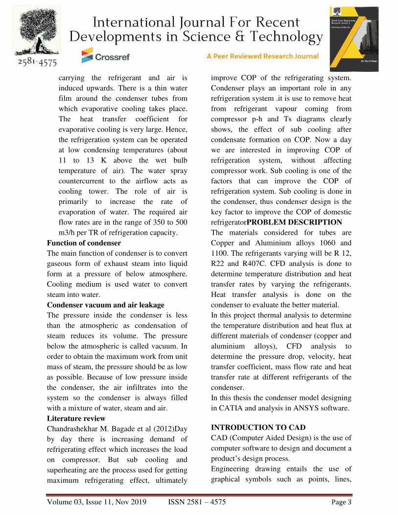
→→Select geometry → right click → import geometry → select browse →open part → ok
Fig - Imported model from Creo 2.0
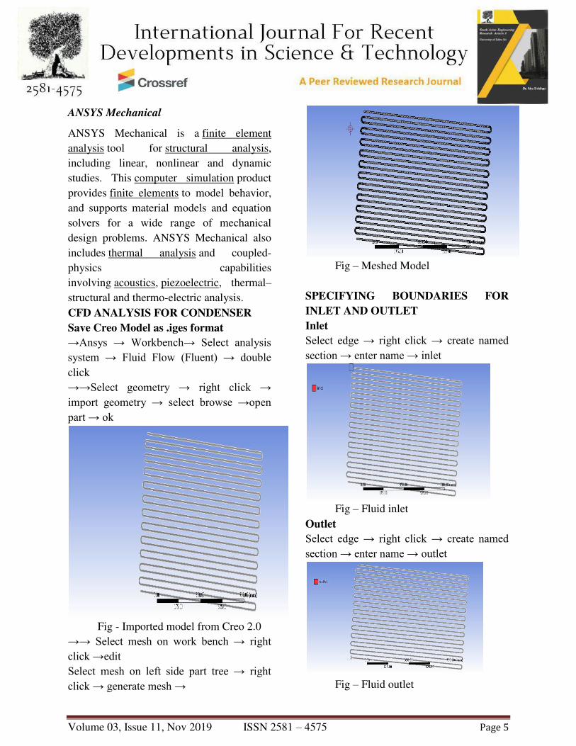
→→ Select mesh on work bench → right click →edit Select mesh on left side part tree → right click → generate mesh →
Fig – Meshed Model
SPECIFYING BOUNDARIES FOR
INLET AND OUTLET
Inlet
Select edge → right click → create named section → enter name → inlet
Fig – Fluid inlet
Outlet
Select edge → right click → create named section → enter name → outlet
Fig – Fluid outlet

Volume 03, Issue 11, Nov 2019 ISSN 2581 – 4575 Page 6
Wall
File export → fluent →input file (mesh) → save required name → save. →→ Ansys → fluid dynamics → fluent → select working directory → ok
→→file → read → mesh → select file → ok.
General →Pressure based Model → energy equation → on. Viscous → edit → k-epsilon
Fig – Viscous Model
Materials → new → create or edit → specify fluid material or specify properties
→ Ok
FLUID - R12
R12 PROPERTIES
INLET BOUNDARY CONDITIONS
Inlet
Inlet Temperature

Volume 03, Issue 11, Nov 2019 ISSN 2581 – 4575 Page 7
Wall
Solution → Solution Initialization → Hybrid Initialization →done
Run calculations → no of iterations = 100→ calculate → calculation complete
→→ Results → graphics and animations → contours → setup
Iteration
Contours of Static Pressure
Contours of Velocity Magnitude
Contours of Static Temperature
FLUID - R12
Open work bench 14.5>select steady state
thermal in analysis systems>select
geometry>right click on the
geometry>import geometry>select IGES
file>open
Imported model
ALUMINIUM 1060 MATERIAL
PROPERTIES
Thermal conductivity of aluminum =
15.1W/mk
Specific heat =356J/Kg K
Density = 0.00000412 Kg/mm3

Volume 03, Issue 11, Nov 2019 ISSN 2581 – 4575 Page 8
Model >right click>edit>select generate
mesh
Meshed model
Boundary conditions
Select steady state thermal >right
click>insert>
Select steady state thermal >right
click>insert>select heat flux
Select steady state thermal >right
click>solve
Solution>right click on
solution>insert>select temperature
Convection
Temperature
Results
Temperature
Heat flux
FLUID - R22
Temperature
Temperature
Volume 03, Issue 11, Nov 2019 ISSN 2581 – 4575 Page 9
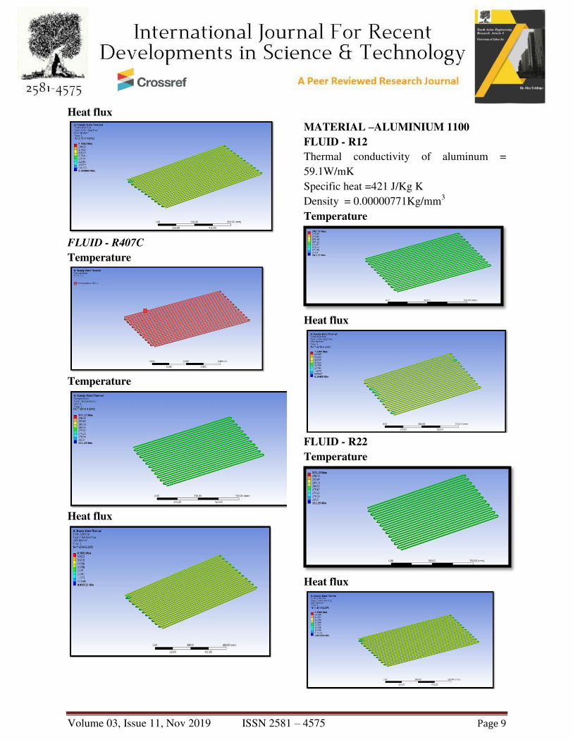
Heat flux
FLUID - R407C
Temperature
Temperature
Heat flux
MATERIAL –ALUMINIUM 1100
FLUID - R12
Thermal conductivity of aluminum =
59.1W/mK
Specific heat =421 J/Kg K
Density = 0.00000771Kg/mm3
Temperature
Heat flux
FLUID - R22
Temperature
Heat flux

Volume 03, Issue 11, Nov 2019 ISSN 2581 – 4575 Page 10
FLUID - R407C
Temperature
Heat flux
RESULTS AND DISCUSSION
CFD ANALYSIS
Fl
ui
ds
Pre
ssu
re
(Pa
)
Tem
perat
ure
(K)
Vel
oci
ty
(m/
Sec
)
Wal
l
Fun
ctio
n
Hea
t
Tra
nsfe
r
Coe
ffici
ent
(W/
m2-
K)
Mas
s
Flow
Rate
(Kg/
Sec)
Tot
al
Hea
t
Tra
nsfe
r
Rat
e
(W)
R1
2
3.1
2e+
06
2.80e+02
1.2
6e+
01
1.08
e+02
-
0.02
7842
855.
549
9
R2
2
3.3
7e+
06
2.83e+02
1.3
6e+
01
1.56
e+02
0.01
3374
329
-
181.
787
11
R4
07
C
1.5
2e+
06
2.83e+02
1.4
7e+
01
1.47
e+02
-
0.01
4236
45
-
48.7
041
02
0.00E+001.00E+062.00E+063.00E+064.00E+06
R22 R134A R407c
PR
ES
SU
RE
(P
a)
FLUIDS
COMPARISON OF PRESSURE
VALUES FOR DIFFERENT FLUIDS
pressure
1.00E+011.20E+011.40E+011.60E+01
VE
LO
CIT
Y
(m/S
EC
)
FLUIDS
COMPARISON OF VELOCITY
VALUES FOR DIFFERENT FLUIDS
velocity
2.78E+022.79E+022.80E+022.81E+022.82E+022.83E+022.84E+02
TE
MP
ER
AT
UR
E (
K)
FLUIDS
COMPARISON OF TEMPERATURE
VALUES FOR DIFFERENT FLUIDS
temperature

Volume 03, Issue 11, Nov 2019 ISSN 2581 – 4575 Page 11
THERMAL ANALYSIS
Material
s
Flu
ids
Conve
ction
(W/m2
K)
Temper
ature
(°C)
Heat
flux
(W/
mm2)
ALUMI
NIUM
1060
R1
2 108 303.15
7.555
8
R2
2 156 303.15
6.584
2
R4
07c 147 303.15
6.583
1
ALUMI
NIUM
1100
R1
2
108 303.15 7.228
5
R2
2
156 303.15 6.298
6
R4
07c
147 303.15 6.297
6
COPPE
R
R1
2
108 303.15 13.13
7
R2
2
156 303.15 11.45
7
R4
07c
147 303.15 11.45
4
0.00E+005.00E+011.00E+021.50E+022.00E+02
R12 R134A R407c
Wa
ll
Fu
nct
ion
…
FLUIDS
COMPARISON OF HEAT
TRANSFER COFFICIENT
VALUES FOR DIFFERENT
FLUIDS
HTC
0
0.01
0.02
0.03
R12 R134A R407c
ss F
low
Ra
te (
Kg
/Sec
)
FLUIDS
COMPARISON OF MASS FLOW
RATE VALUES FOR DIFFERENT
FLUIDS
mass flow
rate
0
500
1000
R12 R134A R407c
TO
TA
L H
EA
T
TR
AN
SF
ER
RA
TE
(W)
FLUIDS
COMPARISON OF HEAT
TRANSFER RATE VALUES FOR
DIFFERENT FLUIDS
total heat
transfer
rate
0
5
10
15
R12 R22 R407C
HE
AT
FLU
X (
W/m
m2)
FLUIDS
COMPARISON OF HEAT FLUX VALUES FOR
DIFFERENT FLUIDS AND MATERIALS
Al 1060
Al 1100
Copper

Volume 03, Issue 11, Nov 2019 ISSN 2581 – 4575 Page 12
CONCLUSION
In this thesis heat transfer by convection in
AC by varying the refrigerants are
determined by CFD and thermal analysis.
The assessment is out on an air-cooled tube
condenser of a vapour compression cycle for
air conditioning system.
The materials considered for tubes are
Copper and Aluminum alloys 1060 and
1100. The refrigerants varied will be R 12,
R22 and R407C. CFD analysis is done to
determine temperature distribution and heat
transfer rates by varying the refrigerants.
Heat transfer analysis is done on the
condenser to evaluate the better material.
By observing CFD analysis results, the heat
transfer coefficient is more when R22 is
used and heat transfer rate is more when
R12 is used than other fluids.
By observing thermal analysis results, the
heat flux is more when R12 is used and
when material Copper is used. (i.e) the heat
transfer rate is more when fluid R22 and
material Copper is used.
REFERENCES
[1]. Experimental Investigation of Split
air Conditioning System by liquid
Based Cooling System by Balaji N,
Suresh Mohan kumar P
[2]. EFFICIENT USAGE OF WASTE
HEAT FROM AIR CONDITIONER
by M. Joseph Stalin, S. Mathana
Krishnan, G. Vinoth Kumar
[3]. Comparitive analysis of an
automotive air conditioning systems
operating with CO2 and R22 by J.
Steven Brown a, Samuel F. Yana-
Motta b,Piotr A. Domanski c
[4]. Performance Enhancement of Air-
cooled Condensers by M. M. Awad ,
H. M. Mostafa , G. I. Sultan , A.
Elbooz
[5]. S.H. Noie-Baghban, G.R. Majideian,
“Waste heat recovery using heat pipe
heat Exchanger (HPHE) for surgery
rooms in hospitals”, Applied
Thermal Engineering, Vol. 20,
(2000) 1271-1282.
[6]. P.Sathiamurthi, R.Sudhakaran
“Effective utilization of waste heat in
air conditioning. Proc. (2003) 13-14.
[7]. P. Sathiamurthi, PSS.Srinivasan,
design and development of waste
heat recovery system for air
conditioner, European Journal of
Scientific Research ISSN 1450-216X
Vol.54 No.1 (2011), Pp.102- 110.
[8]. N.Balaji, P.Suresh Mohan Kumar,
Eco friendly Energy Conservative
Single window Air Conditioning
System by Liquid Cooling with
helical inter cooler ISSN 1450-216X
Vol.76 No.3 (2012), pp.455-462
[9] S.C.Kaushik, M.Singh. “Feasibility
and Refrigeration system with a
Canopus heat exchanger”, Heat
Recovery Systems & CHP, Vol.15
(1995)665 - 673.
[10] R.TugrulOgulata, “Utilization of
waste-heat recovery in textile
drying”, Applied Energy.

Volume 03, Issue 11, Nov 2019 ISSN 2581 – 4575 Page 13