design and analysis an efficient lightweight brake...
TRANSCRIPT

PROJEK SARJANA MUDA
DESIGN AND ANALYSIS AN EFFICIENT LIGHTWEIGHT BRAKE DISC FOR A SINGLE SEATED RACE CAR
NAME : NORAZHAFIDZ AIZAT BIN AHMAD GHAZALI STUDENT ID : B040710147 COURSE : BACHELOR OF MECHANICAL ENGINEERING
(AUTOMOTIVE) SUPERVISOR : EN FUDHAIL BIN ABDUL MUNIR

I
SUPERVISOR DECLARATION
“I hereby declare that I have read this thesis and in my opinion this report is sufficient in term of scope and quality for the award of the degree of
Bachelor of Mechanical Engineering (Automotive)”
Signature :……………………………….. Supervisor :……………………………….. Date :………………………………..

II
DESIGN AND ANALYSIS OF AN EFFICIENT LIGHTWEIGHT BRAKE DISC FOR A SINGLE SEATED RACE VEHICLE
NORAZHAFIDZ AIZAT BIN AHMAD GHAZALI
This thesis is submitted to fulfill a part of the requirement from the terms of graduation of
Bachelor of Mechanical Engineering (Automotive)
Faculty of Mechanical Engineering Universiti Teknikal Malaysia Melaka
May 2011

III
DECLARATION
“I hereby declare that the work in this report is my own except for summaries and quotation which have been duly acknowledge”
Signature :……………………………… Author :……………………………… Date :………………………………

IV
The dedication goes to
my mother and father
for their supports and prayers
V
ACKNOWLEDGEMENTS
This work is dedicated to my parents and family whose supports and prayers
have been endless during a long period of my studies. Thank you very much for
providing me with the best education.
Sincere thanks are due to my final year project supervisor, En Fudhail Bin
Abdul Munir, for unmatched guidance, invaluable advice and knowledge during the
course of this research. Thanks for their expert advice and constructive suggestions
on designing the lightweight disc brake and calculation work throughout my study
period.
A mention must also be given to the present colleagues in Universiti Teknikal
Malaysia Melaka especially to Muhammad Hazwan Bin Mohd Zahri for their
knowledgeable assistance, contributions and suggestions.
I would also like to show my deepest appreciation to my housemates. My
special thanks to Mohd Noor Quddussi Izuywan Bin Mohd Sani and Mohd Khalis
Bin Suhaimi whom always be with me from the start with full support and
encouragement during these difficult times. Thank to everyone that keep me smile
and happy throughout my research.
Finally, I would like to thank Universiti Teknikal Malaysia Melaka (UTeM)
and the Malaysian government for the allowance of RM200 of this research.

VI
ABSTRAK
Sebuah piring brek yang ringan dan berfungsi dengan berkesan
menyumbang kepada prestasi sebuah kenderaan lumba dengan seorang pemandu
sahaja. Di dalam arena lumba kereta, berat sesbuah kereta memainkan peranan
penting dalam mencipta sebuah bahagian pada sesebuah kereta perlumbaan. Berat
yang minima menyumbang kepada kuasa yang maksima. Setiap bahagian pada
sesbuah kereta perlumbaan direka khas atau diubahsuai mengikut piawai kereta
perlumbaan tersebut. Oleh itu, bahan yang ringan dengan “coefficient of friction”
yang tinggi dan kandungan haba yang rendah.akan dipilih melalui kajian analisa
terhadap tegasan haba. Diameter asal piring brek tersebut (Honda Wave 125) di
kurangkan utk mengurangkan berat ia. Berat piring brek tersebut juga bergantung
pada bahan piring tersebut. Analisa tegasan haba ialah salah satu cara kajian tegasan
haba terhadap perubahan suhu atau haba bahan tersebut. Kajian ini hanya bertumpu
pada piring brek sahaja. Selalunya masalah yang menyebabkan berlakunya getaran
pada piring brek tersebut ialah pengembangan haba bahan tersebut mengubah
ketebalan piring brek tersebut. Perubahan ketebalan pada piring tersebut juga
disebabkan oleh fenomena tegasan haba, dimana geseran antara kasut brek dan piring
brek menghasilkan haba. Ketidasekata keadaan haba pada permukaan piring brek
akan di alihkan ke piring brek yang berputar. Fenomena ini menghasilkan tegasan
dan perubahan ketebalan pada piring brek tersebut. Beberapa cara terdapat untuk
mendapatkan keputusan tersebut seperti eksperimen, analisa dan simulasi. Dalam
projek ini, Finite Element Analysis (FEA) digunakan untuk analisa tegasan habapada
piring brek dengan menggunakan perisian simulasi iaitu NASTRAN.

VII
ABSTRACT
An efficient lightweight disc brake contributes to the performance of a
single seated race car. In motorsports arena, the car weight plays very important roles
in designing the race vehicle part. Minimum weight contributes to maximum power.
Each part is custom made according to the vehicle specifications. So that, the
lightweight material with high coefficient of friction and low heat capacity will be
selected through the research in thermal stress analysis. The initial diameter of the
stock brake disc (Honda Wave 125) will be reduced to minimize the weight of the
disc brake. The weight of the disc also contributes by the material of the disc.
Thermal stress is a research of stress due to temperature change. This research only
concentrates on disc brake study. Usually a problem that causes the vibration (known
as brake judder) in disc brake is the material thermal expansion that changes the
thickness of a DTV (Disc Thickness Variation). Thickness change of a disc also is
caused by a thermal stress phenomenon, where as friction between brake pad and
disc brake produces heat. Unbalanced heat condition at the brake surface will be
transferred to rotating disc. This phenomenon will result stress and thickness change
to the disc. There are some method in order to obtain and study this case such
experiment, analysis and simulation. In this project, FEA (Finite Element Analysis)
is used for analysis thermal stress on disc brake by using simulation software called
ANSYS 12.1.

VIII
TABLE OF CONTENT
CHAPTER TITLE PAGES
DECLARATION i-iii
DEDICATION iv
ACKNOWLEDGEMENT v
ABSTRAK vi
ABSTRACT vii
TABLE OF CONTENT viii-x
LIST OF FIGURE xi
LIST OF SYMBOLS xii
CHAPTER 1 INTRODUCTION
1.1 Overview 1-2 1.2 Problem Statement 3-4 1.3 Objectives and Scope 5-6 1.4 Research Methodology 7
CHAPTER 2 LITERATURE REVIEW
2.1 Introduction 8-9 2.2 Brake System Review 2.2.1 History of Brake System
Development 10-11 2.2.2 Vehicle Brake System 12-14 2.2.2.1 Brake Component
and Function 15-18 2.2.2.2 Disc Calipers 19-20

IX
2.2.2.3 Brake Pads 21 2.2.2.4 Brake Disc 22
2.3 Thermal Analysis 22 2.4 Heat Transfer Analysis 23-24 2.5 Thermal Stress Analysis 25-27
CHAPTER 3 METHODOLOGY 3.1 Brake Disc Design 3.1.1 Design Concept 28-32 3.1.2 Summary of the Design 32 3.2 Geometrical Optimization 3.2.1 Effects of Vane Number 33 3.2.2 Effects of Inner and Outer Radius 34 3.2.3 Effects of Vane Offset and Angle 35-36 3.2.4 Effects of Disc Thickness 37 3.3 Disc Face Type 38-39 3.4 Material Selection 39-40 3.4.1 Stages of Material Selection 40-41 3.4.2 General Material Performance Requirement 41-42 3.4.3 Materials Options 43
3.5 Development of Finite Element Model: Modal Analysis 3.5.1 Construction of Disc Brake Model 44-45 3.5.2 Modal Analysis 45 3.5.3 Non-linear Thermal Mechanical Contact Analysis 46 3.5.4 Thermal Boundary Condition 46
CHAPTER 4 RESULTS AND DISCUSSION
4.1 ANSYS Parameter Setting 47-48
4.1.1 Static Structural Analysis 49-51
4.1.2 Steady State Thermal Analysis 52-54

X
4.2 Result Generated From The ANSYS v12.1 Workbench
4.2.1 Static Structural Analysis 4.2.1.1 Equivalent (von-Mises)
Stress 55-56 4.2.1.1 Safety Factor 57-58
4.2.2 Steady State Thermal Analysis 59-62
CHAPTER 5 DISCUSSION
5.1 Discussion 63-64
CHAPTER 6 CONCLUSION
6.1 Conclusion And Recommendations 65-67
REFERENCES 68-72 APPENDICES 73

XI
LIST OF FIGURE
NO TITLE PAGE 1 Vehicle braking system 11 2 Drum brake 13 3 Drum brake components 13 4 Brake system component 15 5 Schematic diagram of forces and moment acting on wheel 15 6 Vented disc 17 7 Brake pad construction 18 8 Vehicle brake system floating piston 19 9 Vehicle brake system rigid piston 19 10 Brake pads 21 11 Vane number vs heat transfer rate 32 12 Inner radius vs heat transfer 33 13 Outer radius vs heat transfer 33 14 Vane angle and vane offset vs total heat transfer rate 34 with 40 vanes 15 Vane angle and vane offset vs total heat transfer rate 35 with 56 vanes 16 Vane angle and vane offset vs total heat transfer rate 36 with 64 vanes 17 Disc thickness vs heat transfer rate with 56 vanes 37 18 Flow chart of material selection method 43 19 Schematic view of real size brake system 44 (brake disc and brake pads) 20 High ventilation holes number 1 51 21 Medium ventilation holes number 1 51 22 no ventilation holes number 1 52 23 High ventilation holes number 2 53 24 Medium ventilation holes number 2 54 25 No ventilation holes number 2 55 26 High ventilation holes number 3 56 27 Medium ventilation holes number 3 57 28 No ventilation holes number 3 57 29 High ventilation holes number 4 58 30 Medium ventilation holes number 4 58 31 No ventilation holes 4 59 32 High ventilation holes number 5 60 33 Medium ventilation holes number 5 60 34 No ventilation holes 5 61
XII
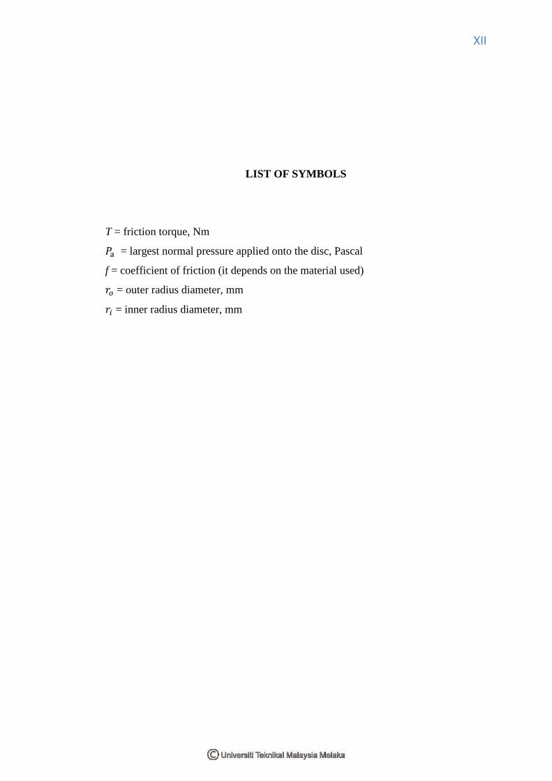
LIST OF SYMBOLS
T = friction torque, Nm
𝑃a = largest normal pressure applied onto the disc, Pascal
f = coefficient of friction (it depends on the material used)
𝑟𝑜 = outer radius diameter, mm
𝑟𝑖 = inner radius diameter, mm

1
CHAPTER 1
INTRODUCTION
1.1 OVERVIEW
Brakes are most important safety parts in the vehicles. Generally all of the
vehicles have their own safety devices to stop their car. Brakes function to slow and stop
the rotation of the wheel. To stop the wheel, braking pads are forced mechanically
against the rotor disc on both surfaces. They are compulsory for all of the modern
vehicles and the safe operation of vehicles. In short, brakes transform the kinetic energy
of the car into heat energy, thus slowing its speed.
Brakes have been retuned and improved ever since their invention. The increases
in travelling speeds as well as the growing weights of cars have made these
improvements essential. The faster a car goes and the heavier it is, the harder it is to
stop. An effective braking system is needed to accomplish this task with challenging
term where material need to be lighter than before and performance of the brakes must

2
be improved. Today's cars often use a combination of disc brakes and drum brakes. For
normal sedan car, normally disc brakes are located on the front two wheels and drum
brakes on the back two wheels. Clearly shows that, together with the steering
components and tires represent the most important accident avoidance systems present
on a motor vehicle which must reliably operate under various conditions. However, the
effectiveness of braking system depends on the design itself and also the right selection
of material. It is important to do some analysis on a disc brake rotor which has been
designed to predict the behavior of the systems than follow with some improvements. In
order to understand the behaviors of braking system, there are three functions that must
be complied for all the time (Smith, 2002);
a) The braking system must be decelerate a vehicle in a controlled and
repeatable fashion and when appropriate cause the vehicle to stop.
b) The braking should permit the vehicle to maintain a constant speed when
traveling downhill.
c) The braking system must hold the vehicle stationary when on the flat or on a
gradient.
Nowadays, there are lot of software has been developed in order to cater the
modeling and the finite element analysis on the vehicle component such as
MSC.ADAMS (Automatic Dynamic of Mechanical Systems), CATIA, MSC
PATRAN/NASTRAN, ANSYS, DYNA and ABAQUS. There is an advantage of using
that powerful computational analysis software where by using those would make it
easier, less cost, better accuracy and less computing time. Most of the software is used in
the wide range of industries such as automotive, oil and gas, aerospace, marine, heavy
duty engineering, construction, electro-mechanical and general mechanical industries. In
this project, design package CATIA and finite element package ABAQUS, ANSYS and
MSC PATRANNASTRAN will be used to generate model and run analysis on the
chosen component.

3
1.2 PROBLEM STATEMENT
A single seated race car needs an efficient brake system. An efficient brake
system requires minimum stopping distance and minimum reaction time. In motorsports
arena, the car weight plays very important roles in designing the race vehicle part.
Minimum weight contributes to maximum power. Each part is custom made according
to the vehicle specifications.
In the current design models for Formula Varsity and EIMA Race vehicle uses
the brake system for motorcycle and a 850cc compact car . Motorcycle brake system
which also includes its disc is only suitable for that particular model. The same goes to a
passenger vehicle brake system. Therefore, there is need to design a new brake disc
which is more suitable for the single seated race vehicle that equipped with the 135cc
engine and below. The brake disc should be lighter in weight but yet efficient.
If looking on the overall automotive parts, besides engines, there are more
crucial parts that engineers need to look into consideration. Suspension, brake, electrical,
hydraulic and gear are all the crucial systems in the automotive areas. Each of all system
has their own functionality which brings life to the automation industries. Brakes is such
a crucial system in stopping the vehicle on all moving stages including braking during
high speed, sharp cornering, traffic jam and downhill. All of those braking moments
give a different value of temperature distribution and thermal stress. Good performance
of disc brake rotor comes from good material with better mechanical and thermal
properties. Good designs of disc brake rotor are varying across the range of the vehicles.
There are different design and performance of disc brake rotor if compared between
passenger, commercial and heavy duty vehicle. There are also other constraints such as
cost, weight, manufacturing capability, robustness and reliability, packaging,
maintenance and servicing. For example, heavy duty vehicle need large size of disc
brake rotor if compared to passenger vehicle. Due to that, it will increased total weight

4
of vehicle as well as fuel consumption and reduces performances of the vehicle.
Moreover, high weight of vehicle induces to high temperature increased during braking
where the higher value of temperature during braking could lead to braking failure and
cracking of disc brake rotor.
This project concerns of the temperature distribution and constraint of the disc
brake. Most of the passenger cars today have disc brake rotors that are made of grey cast
iron (Mackin, 2002). Grey cast iron is chosen for its relatively high thermal
conductivity, high thermal diffusivity and low cost (Mackin, 2002). In this project, the
author will investigate on the thermal issues of single seated race vehicle disc brake ,
where the investigation are to determine the temperature behavior of the disc brake rotor
due to severe braking of the disc brake rotor by using Finite Element Analysis (FEA).
According to (Valvano and Lee, 2000), braking performance of a vehicle can be
significantly affected by the temperature rise in the brake components. High temperature
during braking will caused to:
• Brake fade
• Premature wear
• Brake fluid vaporization
• Bearing failure
• Thermal cracks
• Thermally-excited vibration
Therefore, it is important to study and predict the temperature rise of a given
brake component and assess its thermal performance in the early design stage. Finite
element analysis (FEA) has been preferred and chosen method to investigate some of the
above concerns such as disc brake rotor temperature rise and thermal cracks (Valvano
and Lee, 2000). Finite element analysis for transient analysis will canny out through
ANSYS 12.1 which applied heat transfer analysis where the 3D model imported from
design tools CATIA, while the steady state analysis will be done also by ANSYS 12.1.
5
1.3 OBJECTIVES AND SCOPE
The aim at the end of this project is to design and analysis of a lightweight brake
disc of a single seated race vehicle. In achieving this aim, project objectives are set as
below:
• To understand the working principles, components, standards and theories
through a literature study.
• To understand the working principle of Ansys software (Workbench) and APDL
Mechanical Analysis.
• To understand the fundamental of heat transfer through thermal analysis of disc
brake rotor.
• To clearly justify the result and discussion.
• To find out the total heat flux generated in the brake disk when the process of
braking is done.
• To determine the best design of ventilation holes to avoid thermo elastic
instability.
• Structural analysis is also performed for analyzing the stability of the structure.
The knowledge gained from this project is to be able to understand the steps
needed in thermal analysis of disc brake rotor by using FEA method. The methods used
in this project can later be used in future as reference for similar research and
development. There is the wide range of study on the disc brake rotor. The disc brake
rotor could be studied on the various areas such as material improvement on the disc
brake rotor, vibration on the disc brake, noise and squeal of the disc brake and thermal
stress analysis on the disc brake rotor. However, on this project, the author will intend to
emphasize details on the thermal analysis on the disc brake rotor of a single seated race
vehicle.

6
The scopes of the project are:
• To study the behavior of the suitable material for the brake disc
• To study the behavior of the suitable material for the brake disc
• To do Finite Element Analysis on the designed brake disc.
• To do thermal analysis of the designed brake disc.
• Literature review on the working principles, components, standards and theories.
• Construction of 2D and 3D model of disc brake rotor.
• FE model (Meshing of Geometry model)
• Finite element analysis on steady state and transient analysis which shows the
temperature distribution of disc brake rotor.
• Final justification and conclusion.

7
1.4 RESEARCH METHODOLOGY
A lot of paper and journal has been read up and a part of it has been considered
in this project. Meanwhile, the previous real brake disc dimension has been measured.
CMM has been used in order to get accurate dimension of disc brake rotor. Later, the
precise dimensions have been used to translate in 2D and 3D drawing by using CATIA.
Next, the fractional 3D model of disc brake rotor has been transfer to finite
element software which is ANSYS software. Thermal analysis will be done on steady
state and transient responses. Assigning material properties, load and meshing of the
model will be done in ANSYS software. Finally an expected result of thermal analysis
will be obtained.
For the first step, I have to design the specific dimension of the disc according to
the factor safety value that is 1.5. That is, I reduce the diameter of the disc brake to
decrease the weight of the disc. The efficiency of the brake will be determined on the
thermal elongation and the thermal analysis. So that from the result, we can decide
which one is most efficient according to the thermal analysis. The result for the efficient
on the ventilation holes also can be observed in ANSYS software analysis results.

8
CHAPTER 2
LITERATURE REVIEW
2.1 INTRODUCTION
Disc brakes are an order of magnitude better at stopping vehicles than
drum brakes, which is a disc brake on the front of almost every car and motorbike built
today (Will, 92). Sportier vehicles with higher speeds need better brakes to slow them
down, so disc brakes on the rear of those too. Disc brakes are again a two-part system.
Instead of the drum, the part is a disc or rotor, and instead of the brake shoes, there will
be brake caliper assemblies. The caliper assemblies contain one or more hydraulic
pistons which push against the back of the brake pads, clamping them together around
the spinning rotor. The harder they clamp together, the more friction is generated, which
means more heat, which means more kinetic energy transfer, which slows down the
vehicle. The disc brake or disk brake is a device for slowing or stopping the rotation of a

9
wheel. A brake disc (or rotor in U.S. English), usually made of cast iron or ceramic
composites (including carbon, Kevlar and silica), is connected to the wheel and/or the
axle. To stop the wheel, friction material in the form of brake pads (mounted on a device
called a brake caliper) is forced mechanically, hydraulically, pneumatically or
electromagnetically against both sides of the disc.
Normally, thermal stress analysis has been performed to any of material related
to thermal process in order to oversee the behavior and character of material. Any
abnormality regards to thermal input will give the high values on the stress magnitude of
the studied materials. The high values of stress magnitude will shows deformation on
certain areas which load has been applied on it. Design and analysis of certain parts or
component will took much time and it is costly. Therefore, without any analysis or
design tools, it would be limitations on repeated analysis. For decades, finite element
analysis (FEA) has been a preferred method to address some of the above concerns. It
can be used to compare the design alternatives and hence, optimize the brake rotor
design prior to production of prototype components (Valvano and Lee, 2000). A
literature review was conducted to investigate the past research that has been done in
many areas related to this work. In addition, description, histories, functions and theory
of disc brake rotor will be discussed in this chapter. Furthermore, theory of finite
element method related to thermal analysis will be presented as well in this chapter.

10
2.2 BRAKE SYSTEM REVIEW
2.2.1 History of Brake System Development
In the early days of the automobile, drum brakes were standard. Drum
brakes offered several advantages over other types of brakes. One of these was that the
drum could keep out water and dust, materials that could damage disc brakes which
were out in the open. Major advancement in brake technology came in 191 8 with the
invention of four-wheel hydraulic brake systems by Malcolm Loughead. The hydraulic
brake system replaced the mechanical brake system that was in use at this time. The
mechanical system had numerous disadvantages. It made it difficult to brake all the
wheels evenly, often causing a loss of control. In addition, it required drivers to exert
tremendous amounts of force on the brake pedal to slow the car. The hydraulic brake
system multiplied the force that was applied to the brake, lessening the amount of force
needed to be applied to the brake pedal by the driver. This system was first used in the
1918 Duesenberg. Its advantages quickly caught on and by 1929, four wheel hydraulic
braking systems were standard equipment on higher priced cars. The main problem with
drum brakes is that the heat is not efficiently disbursed. The heat that is produced inside
the drum does not escape easily since the drum prevents wind from drawing it away.
However, disc brakes killed the issues when it allowed the heat to be carried away which
increased the efficiency of the brake. However, their use was limited up until the 1950's
since their efficiency was not required and they required more pedal pressure to operate.
The reason for the higher pedal pressure is that disc brakes have no self-servo effect or
no self-energizing capacity that the drum brakes have. The self-servo effect is caused by
the forward motion of the car. This forward motion helps pull the brake shoe into
contact with the drum. This helped lower the required pedal pressure.
Now that their efficiency was needed and the hydraulic brake system multiplied
the force applied to the brake pedal, disc brakes seemed to be the better alternative.
Chrysler was the first to widely introduce the disc brake in its cars in the early 1950's.

11
The system did not have much success till automaker Studebaker to reintroduce the
system in 1964. This time it saw much more success and in a few years, disc brakes
were common on most new cars. One of the reasons that disc brakes were a success with
the Studebaker and not the Chrysler was due to the development of the power braking
system. Power brakes became common in the 195Ots, after Chrysler had developed and
dropped its disc brake program.
The system assisted the movement of the piston in the master cylinder which
meant that the driver needed to apply less peddle pressure to get the same braking
effectiveness. Therefore, since ease of braking was no longer an issue, the adoption of
the more efficient disc brake became widespread.