design and 3d printing of down-scaled passenger...
TRANSCRIPT
Department of Applied Mechanics
CHALMERS UNIVERSITY OF TECHNOLOGY
Gothenburg, Sweden 2017
Design and 3D Printing of Down-scaled Passenger Vehicle Chassis Bachelor’s Thesis in Mechanical Engineering
Anton Öhammar, Jacob Grundén, Jon Jaleby, Kristofer Arvidsson, Oskar Hellsten,
Simon Medbo

2
BACHELOR’S THESIS IN MECHANICAL ENGINEERING
Design and 3D Printing of Down-scaled Passenger
Vehicle Chassis
Anton Öhammar, Jacob Grundén, Jon Jaleby, Kristofer Arvidsson, Oskar Hellsten,
Simon Medbo
Department of Applied Mechanics
Division of Vehicle Engineering and Autonomous Systems
Vehicle Dynamics Group
CHALMERS UNIVERSITY OF TECHNOLOGY
Gothenburg, Sweden 2017

4
Design and 3D Printing of Down-scaled Passenger Vehicle Chassis
Anton Öhammar, Jacob Grundén, Jon Jaleby, Kristofer Arvidsson, Oskar Hellsten,
Simon Medbo
© Anton Öhammar, Jacob Grundén, Jon Jaleby, Kristofer Arvidsson, Oskar Hellsten,
Simon Medbo, 2017-05-12
Bachelor’s Thesis 2017:04
ISSN 1654-4676
Department of Applied Mechanics
Division of Vehicle Engineering and Autonomous Systems
Vehicle Dynamics Group
Chalmers University of Technology
SE-412 96 Göteborg
Sweden
Telephone: + 46 (0)31-772 1000
Examiner: Bengt Jacobson [email protected]
Supervisor: Ingemar Johansson [email protected]
Department of Applied Mechanics
Göteborg, Sweden 2017-05-12
Design and 3D Printing of Down-scaled Passenger Vehicle Chassis
Bachelor’s thesis in Mechanical Engineering
Anton Öhammar, Jacob Grundén, Jon Jaleby, Kristofer Arvidsson, Oskar Hellsten,
Simon Medbo
Department of Applied Mechanics
Division of Vehicle Engineering and Autonomous Systems
Vehicle Dynamics Group
Chalmers University of Technology
Abstract
To close the gap between the automotive industry and newly graduated engineers the
graduates need to have a better understanding for how their design affects the end
result. This thesis focuses on producing 3D printed suspension scale models with
correct kinematics to help students better understand how different types of
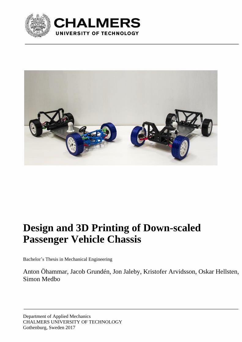
suspensions behave. The suspension types chosen for the models are MacPherson and
double wishbone for the front suspensions and trailing arm multi link suspension and
a live axle for the rear. These models were designed in Catia V5 and then 3D printed
in a scale of 1:5 and assembled together with some off-the-shelf components such as
coilover dampers and ball joints. The models for the MacPherson and the trailing arm
are based on Chalmers suspension setups while the live axle is based on modified
values of the trailing arm. The double wishbone however is primarily based on given
requirements and guidelines from the Chalmers suspension setup. The two front
suspensions feature functioning steering and the MacPherson one also has a
differential to illustrate the function of having a propulsion system. These suspensions
are mounted on two vehicle chassis where the front suspensions can be swapped so all
the combinations can be shown. The curves for camber gain and bump steer are
plotted for the MacPherson and double wishbone suspensions. The 3D printed models
have similar kinematics to the original models. Because of the limited accuracy of 3D
printing there is some play in the suspension components reducing the similarity
between the curves and the real behavior when manipulating the suspensions by hand.
Keywords: vehicle suspension, 3D printing, kinematics, chassis, vehicle dynamics
II
Acknowledgements
We would like to say a special thanks to our supervisor Ingemar Johansson for his
outstanding work and help during this project. Without his expert knowledge and will to help
we would not have come as far nor have the understanding that we today have.
Thank you Ingemar

Preface
This thesis was done as a bachelor thesis at the Mechanical engineering programme of
Chalmers University of Technology, Gothenburg. The work was carried out between
January and May 2017.
Gothenburg May 2017
Anton Öhammar, Jacob Grundén, Jon Jaleby, Kristofer Arvidsson, Oskar Hellsten,
Simon Medbo

IV
Abbreviations
CAD - Computer Aided Design 3D - 3 Dimensional NVH - Noise, Vibrations and Harshness PLA - Polylactide CC - Centre-Centre
RC - Radio Controlled
Contents
Abstract ............................................................................................................................................... I
Acknowledgements ...................................................................................................................... II
Preface ............................................................................................................................................... III
Abbreviations ................................................................................................................................. IV
Contents .............................................................................................................................................. V
1 Chapter One - Introduction ................................................................................................... 1
1.1 Background .......................................................................................................................... 1
1.2 Purpose With the Project ............................................................................................... 1
1.3 Envisioned Solution ......................................................................................................... 1
1.4 Deliverables ......................................................................................................................... 1
1.5 Prerequisites ....................................................................................................................... 1
1.6 Limitations ........................................................................................................................... 2
1.7 Method ................................................................................................................................... 2
1.8 Participants and Function in the Project ................................................................. 2
2 Chapter Two – Background Theory .................................................................................. 3
2.1 Introduction to Vehicle Technology – Wheel Suspension Engineering ..... 3
2.2 Wheel Suspension Parts ................................................................................................. 3
2.2.1 Spring............................................................................................................................. 3
2.2.2 Shock Absorber ......................................................................................................... 3
2.2.3 Coilover Damper ....................................................................................................... 3
2.2.4 Strut ................................................................................................................................ 3
2.2.5 Anti-roll Bar ................................................................................................................ 3
2.2.6 Upright .......................................................................................................................... 4
2.2.7 Control Arm and Link ............................................................................................. 4
2.2.8 Bushing ......................................................................................................................... 4
2.2.9 Ball Joint ....................................................................................................................... 4
2.2.10 Subframe ...................................................................................................................... 4
2.3 Terms and Definitions – Wheel Suspension Engineering ................................ 4
2.3.1 Coordinate System and Forces ........................................................................... 4
2.3.2 Hardpoints ................................................................................................................... 5
2.3.3 Body Roll ...................................................................................................................... 5
2.3.4 Roll Centre ................................................................................................................... 5
2.3.5 Dive and Squat ........................................................................................................... 5
2.3.6 Jounce and Rebound ............................................................................................... 5

VI
2.3.7 Bump Stop ................................................................................................................... 5
2.3.8 Contact Patch .............................................................................................................. 6
2.3.9 Ground Clearance ..................................................................................................... 6
2.3.10 Bump Steer .................................................................................................................. 6
2.3.11 Camber .......................................................................................................................... 6
2.3.12 Caster ............................................................................................................................. 6
2.3.13 Toe .................................................................................................................................. 6
2.3.14 Kingpin .......................................................................................................................... 6
2.3.15 Ground Offset ............................................................................................................. 6
2.3.16 Ackerman ..................................................................................................................... 6
2.3.17 Overtravel .................................................................................................................... 7
2.3.18 Rack travel ................................................................................................................... 7
2.3.19 Load Conditions ........................................................................................................ 7
2.3.20 Wheelbase and Track Width ............................................................................... 7
2.4 Specific Information About the Wheel Suspensions .......................................... 7
2.4.1 Front Suspension – MacPherson ....................................................................... 8
2.4.2 Front Suspension – Double Wishbone ............................................................ 8
2.4.3 Rear Suspension – Trailing Arm ........................................................................ 9
2.4.4 Rear Suspension – Live Axle ............................................................................. 10
3 Chapter Three – Design Engineering ............................................................................. 12
3.1 Off-the-shelf Components ........................................................................................... 12
3.2 MacPherson Suspension ............................................................................................. 12
3.2.1 Subframe ................................................................................................................... 12
3.2.2 Upright ....................................................................................................................... 13
3.2.3 Lower Control Arm ............................................................................................... 14
3.2.4 Coilover Damper Mount ..................................................................................... 14
3.2.5 Anti-roll Bar ............................................................................................................. 15
3.2.6 Assembly ................................................................................................................... 15
3.3 Double Wishbone Suspension .................................................................................. 15
3.3.1 Design Requirements .......................................................................................... 16
3.3.2 Basic Dimensions................................................................................................... 16
3.3.3 Wishbones and Upright Hardpoints ............................................................. 17
3.3.4 Coilover Damper Hardpoints ........................................................................... 19
3.3.5 Steering Hardpoints ............................................................................................. 20
3.3.6 Anti-roll Bar ............................................................................................................. 21
3.3.7 Assembly ................................................................................................................... 21

3.4 Trailing Arm Suspension ............................................................................................. 22
3.4.1 Links ............................................................................................................................ 22
3.4.2 Subframe ................................................................................................................... 23
3.4.3 Upright ....................................................................................................................... 24
3.4.4 Anti-roll Bar ............................................................................................................. 24
3.4.5 Assembly ................................................................................................................... 25
3.5 Live Axle Suspension .................................................................................................... 26
3.5.1 Axle .............................................................................................................................. 26
3.5.2 Support Arm ............................................................................................................ 27
3.5.3 Panhard Rod and Stabiliser Arms .................................................................. 27
3.5.4 Subframe ................................................................................................................... 28
3.5.5 Assembling ............................................................................................................... 29
3.6 Chassis ................................................................................................................................. 29
3.7 Steering ............................................................................................................................... 31
3.7.1 Subframe ................................................................................................................... 32
3.7.2 Steering Rack and Pinion Gear ........................................................................ 33
3.7.3 Pressure Plate ......................................................................................................... 35
3.7.4 Steering Wheel ....................................................................................................... 36
3.8 Tyre and Rim .................................................................................................................... 36
3.9 Simulation .......................................................................................................................... 37
3.10 Manufacturing Parts ................................................................................................. 38
3.10.1 3D Printing ............................................................................................................... 38
3.10.2 Machining Anti-roll Bar ...................................................................................... 39
3.10.3 Machining Chassis ................................................................................................. 39
3.10.4 Assembling/Post Processing ............................................................................ 39
4 Chapter Four – Results ......................................................................................................... 40
4.1 Static .................................................................................................................................... 40
4.1.1 MacPherson ............................................................................................................. 41
4.1.2 Double Wishbone .................................................................................................. 43
4.1.3 Trailing Arm............................................................................................................. 46
4.1.4 Live Axle .................................................................................................................... 48
4.2 Kinematics ......................................................................................................................... 50
4.2.1 MacPherson ............................................................................................................. 50
4.2.2 Double Wishbone .................................................................................................. 52
4.2.3 Trailing Arm............................................................................................................. 55
4.2.4 Live Axle .................................................................................................................... 56
5 Conclusions and Discussion ............................................................................................... 58
VIII
5.1 Conclusions and Fulfilment of Deliverables ....................................................... 58
5.2 Future Work ..................................................................................................................... 58
5.3 Discussion .......................................................................................................................... 59
5.3.1 Plastic Shrinkage ................................................................................................... 59
5.3.2 Coilover Damper Mount Hardpoint ............................................................... 59
5.3.3 Stiffness ..................................................................................................................... 59
5.3.4 Anti-roll Bar ............................................................................................................. 60
5.3.5 Play Between the Parts ....................................................................................... 60
5.3.6 Colour coding .......................................................................................................... 61
5.3.7 MacPherson ............................................................................................................. 61
5.3.8 Double Wishbone .................................................................................................. 62
5.3.9 Trailing Arm............................................................................................................. 62
5.3.10 Live Axle .................................................................................................................... 63
5.3.11 Chassis ........................................................................................................................ 64
6 References ................................................................................................................................. 65
Appendix A - Hardpoints............................................................................................................... 66
A.1 Chalmers MacPherson Suspension .............................................................................. 66
A.2 Double Wishbone Suspension ....................................................................................... 67
A.3 Chalmers Trailing Arm Suspension ............................................................................. 68
Appendix B – Measured Results ........................................................................................... 69
CHALMERS, Applied Mechanics, Bachelor’s Thesis 2017:04 1
1 Chapter One - Introduction
1.1 Background
The car industry of today is evolving and more rapid development cycles are now becoming a
requirement to keep up with the competition in the industry. That is why the newly graduated
engineers of tomorrow need to be even more prepared for the requirements of the industry.
Therefore the universities need to close the gap between graduates and the industry. A step in
this direction is to create the possibility for graduates to have a better understanding of what
their design will result in. Since vehicle dynamics is a subject directly related to an end
product it is essential to have great knowledge of how different suspensions work and how the
theory behind it applies. Bengt Jacobson, Professor in Vehicle Dynamics and leader of the Vehicle Dynamics group,
teaches the course of Vehicle Dynamics at the Master’s Programme of Automotive
Engineering at Chalmers University of Technology. He has identified a need to explain
suspension concepts with downscaled models. This is not easy accessed and with this as a
foundation, a bachelor thesis was formed alongside Ingemar Johansson, Professor of the
practice at Chalmers University of Technology, around the problem with a focus on students
planning a future within the automotive industry. The final result of this thesis is to have
created educational material for further use at the course of Vehicle Dynamics. How these
models will be integrated in the education is not included in this thesis and will instead be a
later task for Bengt Jacobson.
1.2 Purpose With the Project
The course of Vehicle Dynamics explains the dynamic and theory behind wheel suspensions.
Very quickly this becomes a rather complex subject and requires a lot of material and time to
fully explain the basic knowledge these concepts rely upon. To speed up the process
functional models of different wheel suspension would benefit the education and the students
would easier accept further complexity.
1.3 Envisioned Solution
One solution is to build down-scaled models that can function to enhance the education. The
two models should describe and show two different types of suspensions each, a total of four
different suspensions. These are MacPherson strut and double wishbone in the front with a
multi link and live axle suspension in the rear. These models should be able to highlight
different characteristics of suspensions such as camber, ackerman etc. This will thoroughly be
explained later in this report.
1.4 Deliverables
The deliverables are the following:
A front MacPherson suspension model in scale 1:5 with differential and steering
A front Double wishbone suspension model in scale 1:5 with steering
A rear Multi link suspension model in scale 1:5
A rear Live axle suspension model in scale 1:5 without anti-roll bar
Two vehicle chassis with interchangeable front suspensions
1.5 Prerequisites
As a base for this project Chalmers suspension setups are given with associated hardpoints
and guideline values for camber, caster, kingpin, toe-in/out etc. Expert knowledge from
Ingemar Johansson in suspension design engineering is used to break down the information
and convert it into usable information. The Chalmers suspensions hardpoints for a

2 CHALMERS, Applied Mechanics, Bachelor’s Thesis 2017:04
MacPherson and a multi-link suspension are available for reengineering. For the double
wishbone only guideline values, listed in chapter 3.3 are available. Based on this, the
suspensions has to be redesigned and developed to fulfill the given guidelines. Throughout
the report two reference suspensions models hardpoints are used, Chalmers MacPherson
suspension model and Chalmers Trailing arm suspension model. These hardpoints can be
found in appendix A.1 and appendix A.3 respectively.
1.6 Limitations
To restrict the project from becoming too extensive, the work will be focused on suspensions
for passenger cars. More specifically four different suspension setups, namely a MacPherson
and a double wishbone for the front and a trailing arm and a live axle suspension in the rear.
The focus will be on the suspension setup and therefore the propulsion system of the car will
not be considered on three of the four setups. It will however be implemented on the
MacPherson suspension model.
The models will be 3D printed which brings in limitations due to the method itself and the
machines used. What the available 3D printers can handle will limit the size of the models
and components such as joints will be purchased due to difficulty of printing. For 3D printing
there are three printers available with a limited range of different colours on the printing
material. Each printer can be booked for 24 hours per booking by any student that is licensed
to operate the 3D printers. Furthermore the project also has a budget of 4000 SEK which
needs to be taken into consideration when purchasing parts and manufacturing the models. As specified by the project there is also a time limit which spans from 2017-01-17 to 2017-
05-23. Due to the short timeframe and large scope of the project no calculations of the
strength of the printed parts will be made. The design will instead be based on general
engineering methods such as the use of trusses and no sharp transitions.
1.7 Method
The first step of the project is to gain an understanding of how different suspension types
work by studying literature and other sources. With this as a starting point, the next step is to
design four different suspension types in CAD and the CAD software will be Catia V5. The
design process will be based on geometries from the existing Chalmers suspensions to ensure
that the critical points are positioned in the correct places to get a realistic behavior from the
physical models. Consulting with the prototype laboratory during the design process will
ensure that the CAD models are suitable for printing in the 3D printers available at Chalmers.
When the design process has resulted in finished CAD models of the different suspension
types, they will be tested in computer simulations to compare the behavior to real world
suspensions. If the behavior in the simulations is acceptable, the models will be 3D printed
and assembled. After this the models will be measured to ensure that the design criterias are
met.
1.8 Participants and Function in the Project
The thesis is carried out by a team of six students, Anton Öhammar, Jacob Grundén, Jon
Jaleby, Kristofer Arvidsson, Oskar Hellsten and Simon Medbo. The members of the group
study mechanical engineering and aspire to continue a master in automotive engineering. The
functions through the project are divided to create a varied workload where all members get
to test the various roles needed in this project. E.g. the position of administrator is a rotated
post and every second week the role switches to another member. The work has been carried
out as a team work and the team has been able to develop a very efficient work process.
CHALMERS, Applied Mechanics, Bachelor’s Thesis 2017:04 3
2 Chapter Two – Background Theory
2.1 Introduction to Vehicle Technology – Wheel
Suspension Engineering
A car consists of many different systems and parts. Body, body structure, chassis - including
suspensions, and propulsion system. The suspension is the connection between the body
structure and the wheels and allows relative movement between them. This means that it
affects areas such as ride comfort and road grip. If a car were to have no suspension and the
wheels would be connected directly to the body structure, problems would emerge. Mainly
that the imperfections in the road surface would be transferred over with only minor isolation
from the tyres to the body structure. This would result in an extremely stiff and uncomfortable
ride but also in excessive load on the body structure which causes fatigue damage. This
means that the suspension needs to isolate the chassis from movement and forces generated
by the wheels as they follow the road. Another issue to arise is that the wheels would lose
contact with the road causing there to be less grip when the road surface is not perfectly flat
and even. With a suspension however the wheels can follow the surface much better due to
the allowance of vertical movement relative to the body.
2.2 Wheel Suspension Parts
To be able to accomplish the tasks given to the suspension it needs some specific
components. It needs some form of linkage, springs, dampers along other components. There
are also additional components to increase comfort, grip and prevent damage. Under this
chapter all these components are described.
2.2.1 Spring
A springs purpose is to give the desired wheel spring rate to control the wheel. Springs are
often made out of spring steel and can be found in various sizes and shapes, with the most
common version being coil springs. The springs are found on the front and rear suspensions,
often mounted together with a hydraulic shock absorber but also mounted separately.
2.2.2 Shock Absorber
Is normally a hydraulic system designed to dampen and absorb shock impulses. The kinetic
energy is converted to heat through the oil. They are found on both front and rear suspensions
of a car.
2.2.3 Coilover Damper
A coilover damper is a combination of a shock absorber and a spring mounted together. It
integrates both the shock absorber and the spring in an effective way. A double wishbone
suspension is an example of where you can find a coilover damper.
2.2.4 Strut
A strut is essentially the same thing as a coilover except for the fact that it has an axial
bearing at the top to allow for it to rotate around its own centre axis while taking forces
perpendicular to it. It is found in a MacPherson suspension.
2.2.5 Anti-roll Bar
An anti-roll bar, also known as sway bar, is used to give roll stiffness to the chassis and
decrease the body roll of the vehicle and in that way improve the vehicle's handling. It is
connected to the suspension on both sides of the vehicle and improves handling in fast
cornering. The bar itself is connected to the suspension via drop links which are smaller links

4 CHALMERS, Applied Mechanics, Bachelor’s Thesis 2017:04
with ball joints in each end. The anti roll-bar is e.g. used to tune the under- and oversteer
balance in the car.
2.2.6 Upright
The upright carries the wheel bearing with the control arms and links. It is connected to the
subframe or body structure. The MacPherson upright is connected to the body structure with
the lower control arm and the strut. The structural design of the upright is important as it is a
saftey critical part. An upright is found on a variety of different suspensions and its design
depends on the suspension type and design.
2.2.7 Control Arm and Link
Control arms joins the upright and the body structure together and has one degree of freedom.
The control arm has bushings or ball joints in each anchor point to enable some movements.
Depending on which type of suspension and car model the control arm is mounted on it can
have a wide spectrum of different designs, but still with the same function. Links have a
similar function to control arms but with two degrees of freedom.
2.2.8 Bushing
Bushings are used to isolate vibrations to improve ride comfort and NVH as well as to enable
links to move easily when forces are applied. Bushing are usually made from rubber
containing a steel axle in the middle and one as housing to get stiffness and rigid mounting
points. It can be found in various sizes and stiffnesses depending on where and how it is used.
The stiffness rates in the bushings are giving the elasto kinematic performance in the
suspensions.
2.2.9 Ball Joint
A ball joint consist of a bearing stud and socket enclosed in a casing and is made in steel.
Protective sealing often made out of rubber prevents dirt from getting in the joint assembly.
To achieve smooth movement the joint has lubrication sealed in the joint which also
decreases the friction. Modern ball joints are lubricated for life and has no need of replacing
old lubricant. The design allows free smooth movement in two planes at the same time which
is desired in several parts of a suspension.
2.2.10 Subframe
The subframe is a structural component that carries components of the car and gives structural
stiffness. Suspensions, drivetrain and the engine are bolted together with bushings to the
subframe. It is found in both the front and the rear of a vehicle. It is often used to build a front
and rear module as sub assembly, which is preferred in the final assembly of the car.
2.3 Terms and Definitions – Wheel Suspension
Engineering
In automotive engineering many specific terms are used and regarding suspension there is no
exception. Examples of what they describe are different angles, phenomenons or other useful
information.
2.3.1 Coordinate System and Forces
The coordinate system for the Chalmers suspensions are defined as a cartesian coordinate
reference system which can be seen in figure 2-1. Forces parallel the x-axis of a vehicle are
known as longitudinal forces while forces parallel to the y-axis instead are known as lateral
forces. Vertical forces are those parallel to the z-axis of a vehicle.
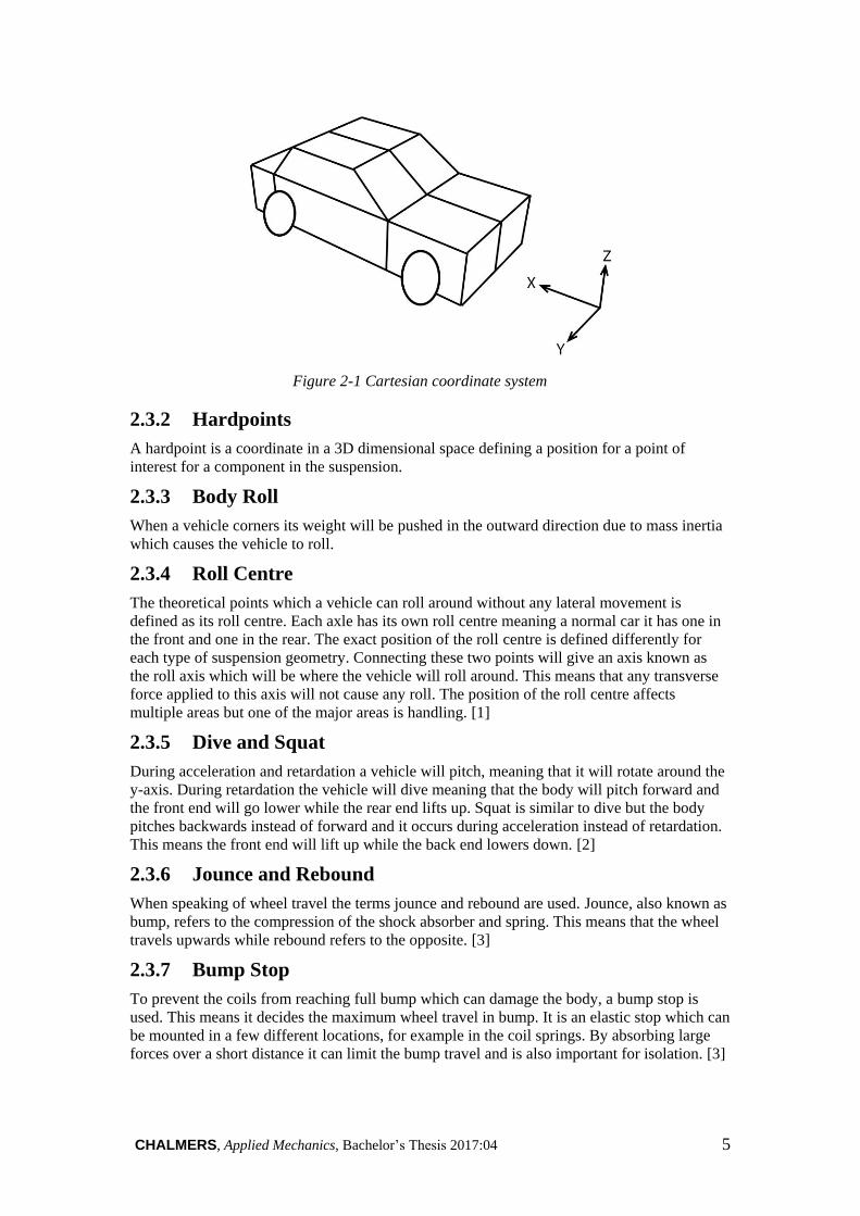
CHALMERS, Applied Mechanics, Bachelor’s Thesis 2017:04 5
Figure 2-1 Cartesian coordinate system
2.3.2 Hardpoints
A hardpoint is a coordinate in a 3D dimensional space defining a position for a point of
interest for a component in the suspension.
2.3.3 Body Roll
When a vehicle corners its weight will be pushed in the outward direction due to mass inertia
which causes the vehicle to roll.
2.3.4 Roll Centre
The theoretical points which a vehicle can roll around without any lateral movement is
defined as its roll centre. Each axle has its own roll centre meaning a normal car it has one in
the front and one in the rear. The exact position of the roll centre is defined differently for
each type of suspension geometry. Connecting these two points will give an axis known as
the roll axis which will be where the vehicle will roll around. This means that any transverse
force applied to this axis will not cause any roll. The position of the roll centre affects
multiple areas but one of the major areas is handling. [1]
2.3.5 Dive and Squat
During acceleration and retardation a vehicle will pitch, meaning that it will rotate around the
y-axis. During retardation the vehicle will dive meaning that the body will pitch forward and
the front end will go lower while the rear end lifts up. Squat is similar to dive but the body
pitches backwards instead of forward and it occurs during acceleration instead of retardation.
This means the front end will lift up while the back end lowers down. [2]
2.3.6 Jounce and Rebound
When speaking of wheel travel the terms jounce and rebound are used. Jounce, also known as
bump, refers to the compression of the shock absorber and spring. This means that the wheel
travels upwards while rebound refers to the opposite. [3]
2.3.7 Bump Stop
To prevent the coils from reaching full bump which can damage the body, a bump stop is
used. This means it decides the maximum wheel travel in bump. It is an elastic stop which can
be mounted in a few different locations, for example in the coil springs. By absorbing large
forces over a short distance it can limit the bump travel and is also important for isolation. [3]

6 CHALMERS, Applied Mechanics, Bachelor’s Thesis 2017:04
2.3.8 Contact Patch
A tyre on a vehicle is deformed by the vertical forces being applied to it. Because of this it
does not only make contact to the road in a single point or line but instead on a surface of the
tyre. This surface or area is called the contact patch of the tyre. [4]
2.3.9 Ground Clearance
Ground clearance or ride height is the distance between the lowest part of the chassis of a
vehicle and the ground. On SUVs this is typically a higher value compared to a regular sedan
and then a sports car usually have an even lower ground clearance. Ground clearance affects
the height of the centre of gravity which in turn affects how much the vehicle will roll and its
handling. [5]
2.3.10 Bump Steer
Bump steer is the unintentional changes in the orientation of the wheels due to vertical travel
of it. Since it causes unintentional steering changes it is normal to try and remove bump steer
effects. [4]
2.3.11 Camber
The camber angle is the angle between a plane perpendicular to the ground and the wheel
seen from the front or back. Camber can be negative, neutral or positive with neutral meaning
0 degrees between the line and wheel. Negative camber is when the top of the wheel is
leaning inwards and positive when it is leaning outwards. [1]
2.3.12 Caster
In a side view the angle between the steering axis and the vertical axis through the wheel
centre is called caster. It is defined as positive when the top of the steering axis is further back
than the bottom. Both handling and steering are areas affected by the caster angle. [1]
2.3.13 Toe
Toe is the angle of the wheels with regards to the centerline of the vehicle when viewed from
above. Toe can be in toe-in, toe-out or zero-toe settings and when wheels are set to toe-in they
point inwards to the centerline. Zero-toe means they are pointing straight ahead along the
centerline and toe-out that the wheels are pointing outwards. A negative toe angle represents
toe-in and a positive toe-out. Changing the toe setting will have an impact on tyre wear,
cornering and also the rolling resistance of the tyre. [2]
2.3.14 Kingpin
Kingpin is the steering axis which is defined as a line through the upper and lower ball joints
in the front suspension. Alongside Kingpin there is also Kingpin inclination which is similar
to the caster angle. Instead of being a view from the side like the caster it is viewed from the
front and is the angle between the vertical plane and the Kingpin. [2]
2.3.15 Ground Offset
The ground offset, or scrub radius is defined as the distance between the kingpin and the
centre of a wheels contact patch where they intersect with the road surface. This when viewed
from the front. This distance is defined as positive when the kingpin intersects with the
ground closer to the centerline of the car than the wheels centerline does. The steering is one
of the areas affected by the ground offset. [1]
2.3.16 Ackerman
Ackerman is a steering geometry with basis in wanting all wheels to roll around a common
point during a turn. To accomplish this with the rear wheels not turning the inner front wheel
CHALMERS, Applied Mechanics, Bachelor’s Thesis 2017:04 7
has to turn more, at a bigger angle, compared to the outer front wheel. This means that the
inner and outer wheel has different turning radius. Using an Ackerman geometry is
advantageous because it reduces the need for the tyres to slip when cornering [6] and reduces
the lateral forces in the steering wheel. The amount of ackermann can be measured in
ackermann percentage. 100% ackermann is when both wheels are traveling at an angle that
makes the two circles concentric and 0% ackermann is when both wheels are traveling with
the same steering angle. The percentage can be calculated with the following formula:
𝑑𝑜 = 𝑠𝑡𝑒𝑒𝑟𝑖𝑛𝑔 𝑎𝑛𝑔𝑙𝑒 𝑜𝑢𝑡𝑒𝑟 𝑤ℎ𝑒𝑒𝑙
𝑑𝑖 = 𝑠𝑡𝑒𝑒𝑟𝑖𝑛𝑔 𝑎𝑛𝑔𝑙𝑒 𝑖𝑛𝑛𝑒𝑟 𝑤ℎ𝑒𝑒𝑙
𝑤 = 𝑤ℎ𝑒𝑒𝑙𝑏𝑎𝑠𝑒
𝑡 = 𝑡𝑟𝑎𝑐𝑘 𝑤𝑖𝑑𝑡ℎ
𝑑𝑎𝑜 = tan−1 (tan(𝑑𝑖))
(1 − tan(𝑑𝑖) ∗𝑡𝑤
) = 𝐴𝑐𝑘𝑒𝑟𝑚𝑎𝑛𝑛 𝑜𝑢𝑡𝑒𝑟 𝑤ℎ𝑒𝑒𝑙 𝑠𝑡𝑒𝑒𝑟 𝑎𝑛𝑔𝑙𝑒
𝐴𝑐𝑘𝑒𝑟𝑚𝑎𝑛𝑛 𝑝𝑒𝑟𝑐𝑒𝑛𝑡𝑎𝑔𝑒 = (𝑑𝑖 − 𝑑𝑜)
(𝑑𝑖 − 𝑑𝑎𝑜)∗ 100
The ackermann percentage is normally calculated at 20 degrees steering angle on the inner
wheel. [5]
2.3.17 Overtravel
Wheel travel is designed to give the acquired wheel travel for normal use, overtravel due to
misuse loads is more than this designed wheel travel. Overtravel needs to be considered for
packaging reasons. [5]
2.3.18 Rack travel
Rack travel is the axial distance the steering rack travels along the y-axis when the wheels are
turned.
2.3.19 Load Conditions
A vehicles weight can be defined in multiple different load conditions. Some of these weights
are: dry weight, wet weight, complete vehicle shipping mass and kerb weight. Complete
vehicle shipping mass is a vehicle's mass with all electrical and auxiliary equipment necessary
for normal operation. This alongside standard or optional equipment from the manufacturer
which should be specified in a list. The definition of kerb weight form [7] is the complete
shipping mass plus the car being filled with all fluids namely lubricants, coolant, washer fluid
and a full tank of fuel, but no passengers or cargo. The +2 stands for that there are two
occupants included in the kerb weight and each occupant's weight is 75 kilograms. The kerb
+2 weight is the weight where the suspensions are designed.
2.3.20 Wheelbase and Track Width
The wheelbase is the length between the centre of the rear and front wheel on the same side of
the car. Furthermore the track width is the length between the centre of the contact patch for
each wheel on the same axis.
2.4 Specific Information About the Wheel Suspensions
Since this project covers four different types of suspension it is self-explanatory that they can
not all work in the same way. This section will distinguish these differences. Three of the four
suspensions are independent which means that each wheel can move independently from the
other. The last one, the live axle, is a dependent suspension which on the contrary means that

8 CHALMERS, Applied Mechanics, Bachelor’s Thesis 2017:04
the wheels can not move independently from one another but instead the second wheel is
affected by first wheel’s movement.
2.4.1 Front Suspension – MacPherson
A MacPherson suspension is commonly used in the front suspension of modern cars due to its
simplicity and low manufacturing cost. The disadvantage is that it usually gives lower quality
of ride and not as good handling of the car because it gives less freedom to choose camber
change and roll centre. Since this is not as important for consumer cars it is a good choice of
suspension setup.
The suspension consists of a lower control arm which is a linkage between the subframe and
the upright and a strut which connects the upright to the body structure. This can all be seen in
figure 2-2. The anti-roll bar can be attached to the shock absorber or the control arm. There is
also a steering connection and there can be a drive shaft connection to the upright and the
wheel respectively.
Figure 2-2 Mcpherson strut. From [8]. CC-BY-SA.
As the control arm is attached to the subframe at two points it allows for one degree of
freedom, rotation around the x-axis. With the help of bushings the control arm also has the
possibility to rotate slightly around the z-axis to withstand the longitudinal forces. A ball joint
connects the control arm and the upright together to enable the wheels to turn. The strut is
fixed to the upright and allows for some movement by a bushing and an axial bearing at the
top mount to cooperate with the change in camber and turning of the wheels. The bushing at
the top mount isolates for ride comfort and NVH. Note that the strut takes pitch and roll
bending moments, thanks to a long piston inside the damper.
2.4.2 Front Suspension – Double Wishbone
A double wishbone suspension is usually found as a front suspension in sports and race cars
but can also be used for a rear suspension. It is used on performance vehicles due to its large
amount of free parameters meaning it has great adjustability and can be optimized for the
vehicle in question.
CHALMERS, Applied Mechanics, Bachelor’s Thesis 2017:04 9
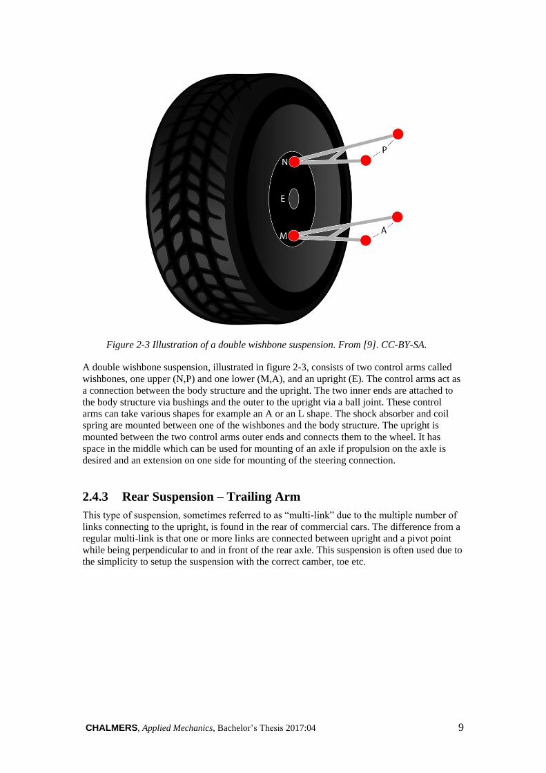
Figure 2-3 Illustration of a double wishbone suspension. From [9]. CC-BY-SA.
A double wishbone suspension, illustrated in figure 2-3, consists of two control arms called
wishbones, one upper (N,P) and one lower (M,A), and an upright (E). The control arms act as
a connection between the body structure and the upright. The two inner ends are attached to
the body structure via bushings and the outer to the upright via a ball joint. These control
arms can take various shapes for example an A or an L shape. The shock absorber and coil
spring are mounted between one of the wishbones and the body structure. The upright is
mounted between the two control arms outer ends and connects them to the wheel. It has
space in the middle which can be used for mounting of an axle if propulsion on the axle is
desired and an extension on one side for mounting of the steering connection.
2.4.3 Rear Suspension – Trailing Arm
This type of suspension, sometimes referred to as “multi-link” due to the multiple number of
links connecting to the upright, is found in the rear of commercial cars. The difference from a
regular multi-link is that one or more links are connected between upright and a pivot point
while being perpendicular to and in front of the rear axle. This suspension is often used due to
the simplicity to setup the suspension with the correct camber, toe etc.
10 CHALMERS, Applied Mechanics, Bachelor’s Thesis 2017:04
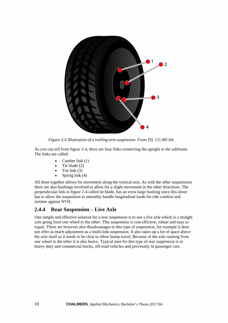
Figure 2-4 Illustration of a trailing arm suspension. From [9]. CC-BY-SA.
As you can tell from figure 2-4, there are four links connecting the upright to the subframe.
The links are called:
Camber link (1)
Tie blade (2)
Toe link (3)
Spring link (4)
All these together allows for movement along the vertical axis. As with the other suspensions
there are also bushings involved to allow for a slight movement in the other directions. The
perpendicular link in figure 2-4 called tie blade, has an extra large bushing since this alone
has to allow the suspension to smoothly handle longitudinal loads for ride comfort and
isolates against NVH.
2.4.4 Rear Suspension – Live Axle
One simple and effective solution for a rear suspension is to use a live axle which is a straight
axle going from one wheel to the other. This suspension is cost efficient, robust and easy to
repair. There are however also disadvantages to this type of suspension, for example it does
not offer as much adjustment as a multi-link suspension. It also takes up a lot of space above
the axle itself as it needs to be clear to allow bump travel. Because of the axle running from
one wheel to the other it is also heavy. Typical uses for this type of rear suspension is in
heavy-duty and commercial trucks, off-road vehicles and previously in passenger cars.

CHALMERS, Applied Mechanics, Bachelor’s Thesis 2017:04 11
Figur 2-5 Axle - 5 Link rigid 03. From [10]. CC-BY- SA.
A live axle suspension has coil springs and shock absorbers like most suspensions but can
also be configured with leaf springs. These coil springs and shock absorbers are mounted
from the body structure to the rear end of a lower support arm but exactly where and how can
vary. These lower support arms, yellow in figure 2-5, are longitudinally mounted on either
side of the vehicle. These are in the forward facing part connected to the chassis with the use
of bushings. This allows for rotation around the y-axis in the mounting point. Towards the
rear they are not just connected to the springs and shock absorbers but also to the main axle.
The main axle is the one running from one wheel to the other and connecting the whole of
this rear suspension. From one side of the axle up to the body structure on the opposite side of
the vehicle runs a Panhard rod, marked as green in the figure. The purpose of the rod is to
restrict the lateral movement of the axle. Mounted between the body structure and the axle
there is also some form of additional control or stabiliser arms, often also an anti-roll bar.
Both design and placement of these arms can vary between different vehicles to suit
packaging.
12 CHALMERS, Applied Mechanics, Bachelor’s Thesis 2017:04
3 Chapter Three – Design Engineering
3.1 Off-the-shelf Components
Since not all the components of the scale 1:5 suspensions could be 3D printed some had to be
purchased. Ball joints were one such component and three different kinds were selected for
use. One is a metal joint and the others plastic. Two of these have M3 sized holes where the
plastic M3 ones has a flat surface on one side of the ball joint and are smaller in size than the
metal ones. The planned use for the plastic M3 ball joints were the steering and to use the
metal ones for everything else except the anti-roll bar drop links. For the drop links smaller
M2 plastic ball joints were chosen. The data for the metal ball joints are as follows:
Shaft diameter: 6.5 mm
Shaft length: 16 mm
Ball centerline to edge: 7 mm
Ball diameter: 7 mm
Joint width: 12 mm
Other components which needed to be purchased were the springs and the shock absorbers.
The available components were from RC cars and they were not springs and shock absorbers
separately but instead coilover dampers. Due to the lengths and stiffnesses desired the options
were limited and lengths could not be perfectly matched. Because the coilover dampers on
RC cars are proportionally longer than on normal cars, smaller scales ones had to be used. For
the rear suspensions scale 1:8 coilover dampers were chosen and for the front two different
lengths of coilover dampers in scale 1:10 were chosen. On all the coilover dampers there are a
ball joints in the lower mounting point and the possibility of adjusting the tension of the
springs. For the planned propulsion system a few components were needed. The core component was
a differential, which was found in scale 1:8. Two axle shafts that keep the wheel in place and
enables propulsion was purchased. A drive shaft in scale 1:8 that matches the axle shafts on
the differential and by the wheel was purchased to link the wheel and differential together.
For the suspensions that does not have propulsion machined axles were purchased. To make
sure that the axles are aligned in the upright and can easily rotate, two bearings are added in
each upright. Bearings were added to all the suspensions and therefore 16 bearings with the
dimension 8x12x3.5 mm was purchased.
3.2 MacPherson Suspension
The front MacPherson suspension was based on an existing suspension. Hardpoints and
principle design of the Chalmers MacPherson suspension model has been used as the basis for
the design of the downscaled suspension model.
3.2.1 Subframe
The subframe had to be designed with a few alterations to what is considered to be a normal
subframe as it has to include a upper strut mount. The strut had to be switched to a coilover
damper as no struts were available for purchase. The differential required a housing to be held
in place and the result can be viewed in figure 3-1. As the differential used is prpportionally
larger than in a normal car it requires a lot more space and the consequence was packaging
problems.
CHALMERS, Applied Mechanics, Bachelor’s Thesis 2017:04 13
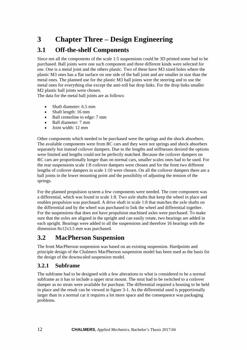
Figure 3-1 Macpherson suspension subframe
The procedure for designing the subframe started out with defining all the relevant hardpoints
in CAD to ensure that the geometry would be correct. From this point an initial design was
delivered to fit the control arms, the upper coilover damper mount and the differential.
Because of the material being PLA the initial design was highly over dimensioned and the
later iterations became cleaner and neater. Unfortunately, it was difficult to find coilover
dampers in the correct dimensions for the model and smaller ones were the only ones
available. To compensate for this the upper coilover damper mount was lowered while still
being in the right angel to give the correct travel of the wheel. When lowering the damper
mount the jounce and rebound measurements of 80 and 110 mm were ensured to still be
correct. The steering rack was forced back from its standard position. The solution to this is
further explain under chapter 3.8.
Traditionally, a MacPherson suspension is designed with the anti-roll bar connected to the
shock absorber. It was discovered that attaching an anti-roll bar to the shock absorber would
be very difficult and instead it was attach to the lower control arm. By doing this the anti-roll
bar could be attached on the top of the differential housing.
3.2.2 Upright
To get the base for the upright the relevant hardpoints from the Chalmers MacPherson
suspension were put up in a 3D CAD space. The shape was created by surrounding these
points with material and connecting these. This gave a main body with space for the hole to
fit the axle, a structure for mounting the coilover damper, a place for attaching the lower
control arm and an arm for the steering connection. To be able to mount the coilover damper
in the correct angle a hole through the upper part of the upright was needed. This was made
by adding the upper hardpoint for the coilover damper and draw a line between this and the
lower coilover damper point. To make sure the coilover damper mounting was well secure a
slot for a screw-nut was also added. Additionally after testing a guard rail was added to keep
the spring from moving around. The connection to the lower control arm was made through a
ball joint. To allow this ball joint to have full movement a spacer with a conical shape was
added on the bottom. For attachment of the ball joint a screw was used which meant another
slot for the nut was made. For the bearings a ledge was added in the centre of the hole for the
axle this to hold them in place. To allow the axle to rotate freely and be mounted correctly
space was added around the hole on the inside of the upright. The upright can be seen in
figure 3-2.

14 CHALMERS, Applied Mechanics, Bachelor’s Thesis 2017:04
Figure 3-2 MacPherson upright
3.2.3 Lower Control Arm
The lower control arm was designed by inputting the correct hard points in Catia V5 and by
visually analysing how the original control arm was designed. The three hard points forces the
design to become a L-shaped control arm and with the initial design finished a first version
was printed. With this version discoveries was made such as too tight fit for e.g. the
connection to the subframe unabling the control arm to move properly. The anti-roll bar
attachment was later in the project decided to be fitted on the control arm and the attachment
point was put as far out on the control arm as possible to make the anti-roll bar as effective as
possible. The end result can be shown in figure 3-3.
Figure 3-3 MacPherson lower control arm
3.2.4 Coilover Damper Mount
Since the coilover damper is an off-the-shelf component and designed for a RC car it was not
the exact length and lacked a ball joint in the top. To solve the problem of length the coilover
damper mount in the subframe was lowered. Since the ball joint was missing on the coilover
damper a solution was to create a mount on top of the damper. It also has an attachment for a
ball joint in horizontal position that is mounted together on the subframe. This design, seen in
figure 3-4, enabled both the motion to be as correct as possible and was easy to manufacture.
Figure 3-4 Coilover damper extension
CHALMERS, Applied Mechanics, Bachelor’s Thesis 2017:04 15
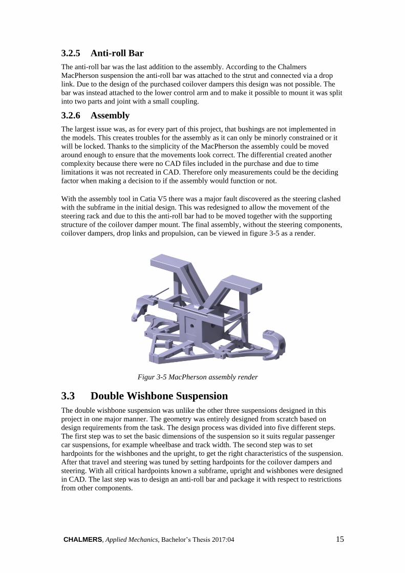
3.2.5 Anti-roll Bar
The anti-roll bar was the last addition to the assembly. According to the Chalmers
MacPherson suspension the anti-roll bar was attached to the strut and connected via a drop
link. Due to the design of the purchased coilover dampers this design was not possible. The
bar was instead attached to the lower control arm and to make it possible to mount it was split
into two parts and joint with a small coupling.
3.2.6 Assembly
The largest issue was, as for every part of this project, that bushings are not implemented in
the models. This creates troubles for the assembly as it can only be minorly constrained or it
will be locked. Thanks to the simplicity of the MacPherson the assembly could be moved
around enough to ensure that the movements look correct. The differential created another
complexity because there were no CAD files included in the purchase and due to time
limitations it was not recreated in CAD. Therefore only measurements could be the deciding
factor when making a decision to if the assembly would function or not. With the assembly tool in Catia V5 there was a major fault discovered as the steering clashed
with the subframe in the initial design. This was redesigned to allow the movement of the
steering rack and due to this the anti-roll bar had to be moved together with the supporting
structure of the coilover damper mount. The final assembly, without the steering components,
coilover dampers, drop links and propulsion, can be viewed in figure 3-5 as a render.
Figur 3-5 MacPherson assembly render
3.3 Double Wishbone Suspension
The double wishbone suspension was unlike the other three suspensions designed in this
project in one major manner. The geometry was entirely designed from scratch based on
design requirements from the task. The design process was divided into five different steps.
The first step was to set the basic dimensions of the suspension so it suits regular passenger
car suspensions, for example wheelbase and track width. The second step was to set
hardpoints for the wishbones and the upright, to get the right characteristics of the suspension.
After that travel and steering was tuned by setting hardpoints for the coilover dampers and
steering. With all critical hardpoints known a subframe, upright and wishbones were designed
in CAD. The last step was to design an anti-roll bar and package it with respect to restrictions
from other components.

16 CHALMERS, Applied Mechanics, Bachelor’s Thesis 2017:04
3.3.1 Design Requirements
The following requirements were given for the double wishbone suspension. The data was
given in kerb +2 and full scale. Dimensions:
- Camber = -0.5 degrees, +/- 0.1 degrees tolerance - Toe in = 0 degrees, +/- 0.1 degrees tolerance - Lower wishbone angle = 0 degrees, +/- 0.1 degrees tolerance - Camber gain = 21 degrees/meter, +/- 1 degrees tolerance - Caster = 0 degrees, +/- 0.1 degrees tolerance - Ground offset = 10 mm , +/- 0.1 mm - Roll centre = 60 mm, +/- 1 mm - Wheel offset = 52 mm, +/- 1 mm - Bump steer = 15 degrees/meter, +/- 1 degrees tolerance - Travel = -110 +80 mm, +/- 3 mm - Wheel = 235/50 R19 8.0x19x52 - Static loaded radius = 85% of tyre profile - Ackermann percentage at 20 degrees steering angle at inner wheel = 10-20%
General input: - Package the outer control arm ball joints as wide as possible in z-direction - Let the steering link be parallel to lower control arm - Symmetry about the centre of the wheel in the x-direction
3.3.2 Basic Dimensions
The right characteristics can be achieved independent of the models size as long as the
relations between all parts are correct. Some different dimensions can more or less be set
without affecting the characteristics, if the design thereafter is made with respect to these
dimensions. The dimensions are: subframe lower width, subframe upper and lower depth,
lower wishbone length and spread of outer wishbone ball joints in the z-direction. To obtain
realistic dimensions, known hardpoints from the Chalmers Macpherson suspension was used
and scaled to 1:5. The lower MacPherson control arm dimension in the z-direction rounded up
to closest integer led to 80 mm lower wishbone (Q, in figure 3-6) length in y-direction.
With the lower wishbone length and MacPherson track known alongside the horizontal lower
wishbone requirement the subframe (S) lower width could be calculated to 147.6 mm in y-
direction. The measurement between outer wishbone ball joints (M,N) is set so that there
won’t be packing problems under any circumstances. Distance from centre of ball joint to ball
joint shell was unknown at this stage of the development so an extreme case was estimated to
6 mm as scaled dimension. Distance from ball joint centre to rim was set to 14 mm according
to the Chalmers Macpherson suspension, the inner rim distance was 96.5 mm. That gave a
spread between outer wishbone ball joints (M,N) of 56.4 mm. At last the width of upper and
lower wishbone was considered, x-direction. It was not a critical measurement so the upper
wishbone (R) was set to the same as the Chalmers Macpherson suspension lower wishbone
(Q) and the lower to the same dimension plus 10 mm to add extra stiffness.
CHALMERS, Applied Mechanics, Bachelor’s Thesis 2017:04 17
Figure 3-6 Basic dimensions [mm]
3.3.3 Wishbones and Upright Hardpoints
To obtain the right camber, caster, roll centre and ground offset, hardpoints for wishbones
and upright were calculated. The design was done in a 2D sketch using Catia V5. Known
basic dimensions were designed along with tyre and rim. To acquire the desired camber in
design position the wheel was tilted 0.5 degrees negative while setting all hardpoints.
Thereafter the upper wishbone outer ball-joint (N, in figure 3-7) hardpoint was set by
designing a straight line through the lower ball joint (M) and ground offset point (T). Along
that line the upper wishbone outer ball-joint hardpoint (N) was set. It was placed with the
desired spread of 56.4 mm between the outer wishbone ball joints (M,N). The scrub radius
point (T) was placed at the static load radius with an offset of 2 mm from wheel centre in y-
direction. The deformation of the tire was also taken into consideration by subtracting 15% of
the wheel profile radial while setting the ground offset point [5].
Figur 3-7 Upright hardpoints
Up until this stage the hardpoints that was set, in some words only determined static
properties. The dynamic properties of the suspension require more advanced calculations and
was based on the following method. The upper wishbone inner hardpoint (P, in figure 3-8)
was set by using two restrictions, the given roll centre (U) and camber gain. The upper
wishbone was extended with a line and a line was also drawn from where the wheel centre

18 CHALMERS, Applied Mechanics, Bachelor’s Thesis 2017:04
intersected with the ground. The lines was drawn out until they intersected with each other on
the left and right side of the wheels. The roll centre (U) was defined by the point where the
two lines from the ground offset intersect each other [4]. This point was therefore placed 12
mm above the ground according to the given data. That makes the made up geometry
constrained regarding angels. The upper wishbone (R) got an angle of 6.3 degrees to the
horizontal plane, as long as that angle and the so far set hardpoints are kept the correct roll
centre will be achieved [11].
Figur 3-8 Roll centre design
The camber gain was then set by placing the upper wishbone inner hardpoint (P, in figure 3-9)
at a calculated position along the 6.3 degrees construction line. This position was obtained by
using circles, two circles had their radius set by the upper (R) and lower (Q) wishbone
according to [4]. The change in y-direction after a certain change in z-direction could be
obtained by following the border of the circles. The third circle (C3) was given the same
radius as the length of the upright (E1), the centre of the circle was moved 4 mm in the z-
direction and the radius line (E2) was connected to the upper circle (C2). The camber gain
after 4 mm travel was then given by the angle difference between the upright (E1) and the
radius line (E2). The length of the upper wishbone was adjusted until 0.46 degrees angle was
obtained/4 mm travel.
Figure 3-9 Camber gain

CHALMERS, Applied Mechanics, Bachelor’s Thesis 2017:04 19
3.3.4 Coilover Damper Hardpoints
The correct travel was obtained by setting hardpoints for the coilover damper (D, in figure 3-
10). The desired travel of +80 mm and -110 mm on a full scale vehicle which gave a total
travel of 38 mm (1) in scale 1:5. The coilover damper that was used has a travel of 18 mm
that gives a needed gear ratio of 2.1:1 (2) to acquire the accurate travel at the wheel centre.
Some simplifications were made in the calculations. The angle of the coilover damper was not
taken into account and the travel was said to be solely determined by the movement of the
lower wishbone movement around its inner attachment and the extended lever that the upright
(E) and rim contributes with, this simplification contributed to the desired extra travel and
was therefore motivated. It is good to have extra travel when it comes to visualization and
education. The total length of moving lever was then 82 mm.
The simplifications made it possible to let the attachment position of the coilover damper
along the lever be used to get the right travel at wheel centre, a ratio of 2.1 gives that the
coilover damper lower attachment (B) needed to be placed at most 47.6% (3) from the lower
wishbone inner attachment (A). With a lever of 82 mm the coilover damper lower attachment
(B) needed to be placed at most 39 mm (4) from the lower inner wishbone attachment (A),
one millimeter was subtracted from the required measurement to be conservative and on the
right side of the limit. That gave a final placement for the coilover damper lower end (B) of
38 mm (5) from the lower inner wishbone attachment (A). The upper coilover damper attachment (C) was placed so that the total travel of the coilover
damper gave 16 mm compression and 22 mm extension which correlated to the relationship
with the desired travel of +80 mm and -110 mm on a full scale vehicle (6). Fully extended the
coilover damper is 78 mm, that gave a compressed length of 65.6 mm (7) in kerb +2 design
position. The coilover damper was centered in y-direction within the v-shaped area of the
upper wishbone. That gave a y-position for the coilover damper upper attachment, 6 mm in
the y-direction from the upper wishbone inner attachment. From the compressed design
position of the coilover damper (7) and after centering the coilover damper, the upper
attachment (C) position in the z-direction was set to 9.2 mm from the upper wishbone inner
attachment. The hardpoints that were set in the previous steps were generated in a design
environment and was verified as correct in a later stage, first through assembling in CAD and
then physical testing. There was no need for reengineering.
Figure 3-10 Coilover damper hardpoints [mm]

20 CHALMERS, Applied Mechanics, Bachelor’s Thesis 2017:04
(1) (80 + 110) ∗ 0.2 = 38 𝑚𝑚 (2) 38/18 = 2.1
(3) 1/2.1 = 0.476
(4) 0.476 ∗ 82 = 39 𝑚𝑚 (5) 39 − 1 = 38 𝑚𝑚
(6) (80
190) ∗ 38 = 16 (
110
190) ∗ 38 = 22 𝑚𝑚
(7) 76 −110
190∗ 18 = 65.6 𝑚𝑚
3.3.5 Steering Hardpoints
The main steering properties that are affected by the steering hardpoints are Ackermann and
bump steer. The same set of dimensions affects both of these properties. Therefore an
iterative process was needed to achieve numbers on those two properties that were within the
requirements. The starting point when setting these points was the upright from the Chalmers
MacPherson suspension model. This upright has a CC offset from the kingpin axle (G, in
figure 3-11) to the outer tie rod ball joint (I) of 31.2 mm and a distance of 2.1 mm in the y-
direction. Those dimensions were used and the position in the z-direction was determined by
the inner tie rod ball joint (J) and the criteria that the tie rod should be level to the lower
wishbone.
The steering rack (H) was designed with 18 mm offset in the z-direction from the bottom to
the tie rod ball joint (J), the bottom is the surface that will be mounted flush to the subframe.
From the flat attachment surface of the subframe there was an additional 3.5 mm of offset to
the lower wishbone inner attachment (A) that was used as reference when setting the steering
hardpoints. That made a total of 21.5 mm from the lower wishbone inner attachment (A) to
the inner tie rod ball joint (J) in the z-direction. To meet the requirement of parallel tie rod
and lower wishbone, the outer tie rod ball joint (I) was placed 21.5 mm from the lower outer
wishbone ball joint in the z-direction. Thereby base dimensions in all degrees of freedom
were given for the outer tie rod ball joint (I). The inner tie rod ball joint (J) already had a given position in the z-direction, the position and
travel in the y-direction is given by the Chalmers MacPherson suspension model. 73.8 mm
from the centre of the car and a travel of 16.5 mm in each direction. The position in the x-
direction was at first set so the tie rod is parallel with the y-axis. Thereafter the inner tie rod
ball joints was moved in x and z direction until the right bump steer and ackermann was
achieved [4]. By changing the position in z-direction the bump steer was mainly affected. By
moving it in x-direction the ackermann was mainly affected. The final x-direction position
was 41.5 mm from wheel centre and the final z-position was 21.5 mm from the lower inner
wishbone attachment which was the same as the original position from the steering rack
height.

CHALMERS, Applied Mechanics, Bachelor’s Thesis 2017:04 21
Figure 3-11 Steering hardpoints [mm]
3.3.6 Anti-roll Bar
The purpose of the anti-roll bar on the model was to show the basic functions. The design was
therefore only based on packaging limitations. The drop link (K, in figure 3-11) lower end
moves towards the upright and the front of the vehicle while the wheel travels due to the
upper wishbone rotation centre. Therefore the drop link (K) lower end was tilted towards the
rear and centre of the car in design position to counteract the unintentional movement. The
drop link and outer end of the anti-roll bar was placed as far as possible from the centre of the
car and the two ends were combined by a U shaped anti-roll bar (L) supported by bushings in
the subframe according to [11]. The anti-roll bar was designed with a coupling in the centre to
make it possible to detach it when desired.
3.3.7 Assembly
During the whole design process parts were designed in CAD immediately after hardpoints
that were linked to the specific parts were calculated. It was done to be able to assemble the
parts in CAD and make sure that they work together as expected before setting other
hardpoints that could be affected by limitations detected in the assembly, but also to avoid
manufacturing faulty parts. The part design was done by connecting hardpoints of each part in
a esthetic and mechanically necessary way but without concern of stiffness. The complete
assembly of the suspension can be seen in figure 3-12, all designed parts are included except
from the premanufactured ball joints and bearings.

22 CHALMERS, Applied Mechanics, Bachelor’s Thesis 2017:04
Figure 3-12 Render of double wishbone assembly
3.4 Trailing Arm Suspension
The trailing arm suspension was the other suspension being reengineered from an existing
setup. Hardpoints were given from the Chalmers Trailing Arm suspension. The main task was
therefore to connect those hardpoints by both the different links and a subframe.
3.4.1 Links
The links were designed one by one. With the coordinates for each point put into Catia V5 the
shape between them were drawn by the usual looks of the parts to get the the model to be as
realistic as possible according to the Chalmers suspension. They were all made planar and
straight except for the tie blade and the camber link. The tie blade, figure 3-15, was made
with a slight bend to allow for it to stress the point on the subframe in a longitudinal direction
without to much rotation when such forces are applied. This shape also makes it rotate well
when the wheel is traveling in a vertical direction. The camber link, figure 3-13, was designed
with an “s-shape” to clear the side member, which is a part that supports the side structure of
the car and adds strength, as the problem of packaging everything in the space available is a
common problem. The spring link, figure 3-16, was designed as a flat piece with a circular
platform in the middle where the spring would sit on the real size car without a coilover
damper. It was also designed with a slot where the coilover damper could be slid into and
secured with a screw. The toe link can be seen in figure 3-14.
Figure 3-13 Camber link

CHALMERS, Applied Mechanics, Bachelor’s Thesis 2017:04 23
Figure 3-14 Toe link
Figure 3-15 Tie blade
Figure 3-16 Spring link
The first drafts were mostly kept in the final design except for the holes which were
redesigned with a conical shape, which represents a bushing, to allow for them to twist as the
wheel suspension would get over constraint otherwise.
3.4.2 Subframe
With the inner hardpoints used to design the links, the subframe could also be designed as it
uses exactly the same ones. These were put into a 3D space and connected in a manner that
would take as little space, and plastic from the 3D printer as possible, but still be stiff enough
to not get any fractures. As stated in the project there were no calculations done to verify the
strength of the frame, but they were designed in a way that reminds of a truss, which is known
among mechanical engineers to be a durable design. As this part was the first one to be test-
printed there was a difference in the design since the strength of the PLA was at that point
unknown. After some testing it was found to be too little play between the subframe and the
links. It was also thicker than necessary and therefore a lot of material was removed before
the next print to save material and lower the time in the printer.

24 CHALMERS, Applied Mechanics, Bachelor’s Thesis 2017:04
To get the correct percentage of jounce and rebound, the hardpoint for the upper mount of the
coilover had to be moved 2.3 mm upwards along its central axis. As the hardpoint stayed on
the axis, the movement of the suspension would not be affected. The final design of the
subframe can be seen in figure 3-17.
Figure 3-17 Subframe trailing arm
3.4.3 Upright
Based on the outer hardpoints of the links the upright, figure 3-18, was created. The
hardpoints were placed in the 3D space in Catia V5 and linked together to a straight block.
Refinement of the shape was made and attachment points were created for the different links.
As could be seen in an assembly of the whole suspension in Catia V5, there were problems
with getting everything to fit in the rim. There were also a few brackets for the links that were
under dimensioned and therefore broke. Because of this a redesign of the upright was made.
After 3D printing the prototype and mounting it together with all components, areas in need
of improvement were detected. Improvements such as removing material that was blocking
the links from proper movement was done. There were also slots made to fit the bearings for
the wheel axle.
Figure 3-18 Upright trailing arm
3.4.4 Anti-roll Bar
With gathered knowledge of the function of an anti-roll bar it was designed based on
available space, hardpoints and maximum functionality. The drop link was made out of two
ball joints and the anti-roll bar itself out of a 2 mm steel rod. The rod was machined by
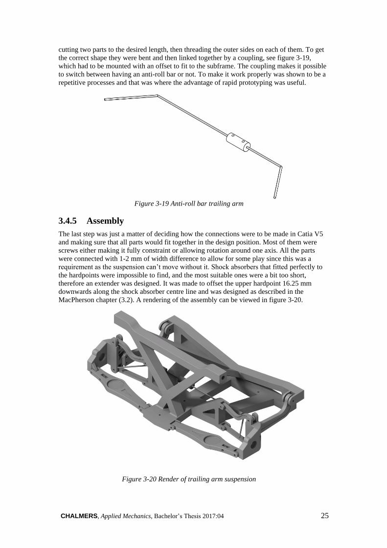
CHALMERS, Applied Mechanics, Bachelor’s Thesis 2017:04 25
cutting two parts to the desired length, then threading the outer sides on each of them. To get
the correct shape they were bent and then linked together by a coupling, see figure 3-19,
which had to be mounted with an offset to fit to the subframe. The coupling makes it possible
to switch between having an anti-roll bar or not. To make it work properly was shown to be a
repetitive processes and that was where the advantage of rapid prototyping was useful.
Figure 3-19 Anti-roll bar trailing arm
3.4.5 Assembly
The last step was just a matter of deciding how the connections were to be made in Catia V5
and making sure that all parts would fit together in the design position. Most of them were
screws either making it fully constraint or allowing rotation around one axis. All the parts
were connected with 1-2 mm of width difference to allow for some play since this was a
requirement as the suspension can’t move without it. Shock absorbers that fitted perfectly to
the hardpoints were impossible to find, and the most suitable ones were a bit too short,
therefore an extender was designed. It was made to offset the upper hardpoint 16.25 mm
downwards along the shock absorber centre line and was designed as described in the
MacPherson chapter (3.2). A rendering of the assembly can be viewed in figure 3-20.
Figure 3-20 Render of trailing arm suspension

26 CHALMERS, Applied Mechanics, Bachelor’s Thesis 2017:04
3.5 Live Axle Suspension
Since there were no existing live rear axle information to begin with the base was taken from
the trailing arm suspension. The existing information, such as hardpoints, from the trailing
arm was combined with photos of a live axle suspension setup from a Volvo 940 and a
schematic image of another live axle version, see figure 3-21. This was done to be able to
reengineer a new live axle suspension with trustworthy accuracy and correctness, but due to
the lack of information the suspension is not entirely correct.
Figure 3-21 Axle - 5 Link rigid 03. From [11]. CC-BY- SA.
3.5.1 Axle
Since the axle itself is the main part of a live axle suspension that was the starting point. From
the hardpoints of the Chalmers trailing arm suspension the y-coordinate for the wheel centre
was given and with it the length of the axle could be calculated as:
L = 2 ∗793.2
5= 317.3 mm
This gives the length to be 317.3 mm in scale 1:5, but since that was too long for the 3D
printer available it was split in half. In the centre of the axle a sphere was placed to represent
the rear final gear. This was instead of an actual final gear since the model will not have a
propulsion system on this axle. On each end of the axle mounting for the wheels was
required. This was done with the help of two bearings so the diameter at each end needed to
be increased to accommodate them. It also needed to have space for a screw to be screwed
through the bearings, with a slot on the inner side to allow mounting of a screw-nut.
Furthermore the panhard rod needed some form of mounting which was made as a hole
through the axle and a spacer, similar to what is seen in figure 3-21. The spacer was needed to
stay clear of the thought final gear as the axle moves vertically. The final part of the axle was
the mounting for the additional stabiliser arms. This mount was made to accommodate ball
joints so that the axle would not be locked in any direction except revolving around its own
centre line. An additional guard on each side for the support arms had to be added so that they
would not move around along the axle. The final design can be seen in figure 3-22.

CHALMERS, Applied Mechanics, Bachelor’s Thesis 2017:04 27
Figure 3-22 Axle
3.5.2 Support Arm
Close to the end on both sides a support arm, see figure 3-23, is mounted to the axle and
connects it to the coilover damper. The support arm has no exact equivalent on the trailing
arm but the hardpoints for the tie blade were used to get an approximation of the length and
height difference. This gave the basic dimensions and made it possible to move on and create
a mounting point for the coilover damper. Most live axle suspensions uses separate springs
and shock absorbers and therefore two mounting points. With the coilover damper purchased
only one mounting point was needed and the one where the springs are originally mounted
were chosen. Since the bought coilovers had a ball joint in the lower mounting point all that
was needed was a vertical slot to accommodate the ball joint and a horizontal hole for a
screw.
The next part was mounting the axle itself to the support arm. The axle needs to be able to
rotate around the x-axis of the car and because the arm will move vertically special mounting
was needed. This was done by narrowing and rounding the arm where the axle is to be
mounted. A similar design with the rounding was done on a complementary piece to be able
to strap the axle down onto the support arm. This design should allow for more movement
and not cause the suspension to be completely rigid. Since there are no bushings the holes to
mount the support arm to the subframe were made with a conical shape to also allow for some
movement.
Figure 3-23 Support arm with complementary piece
3.5.3 Panhard Rod and Stabiliser Arms
Both the stabiliser arms, figure 3-24, and the Panhard rod, figure 3-25, were made as straight
round rods in appropriate lengths. Since these are screwed in with ball joints all ends needed
to be made with a hole to accommodate them. The holes needed to be 16 mm deep and have a
diameter of 6.5 mm so that the ball joints would fit. Instead of having the entire Panhard rod
having a uniform thickness the middle part as made thinner to not waste material. The
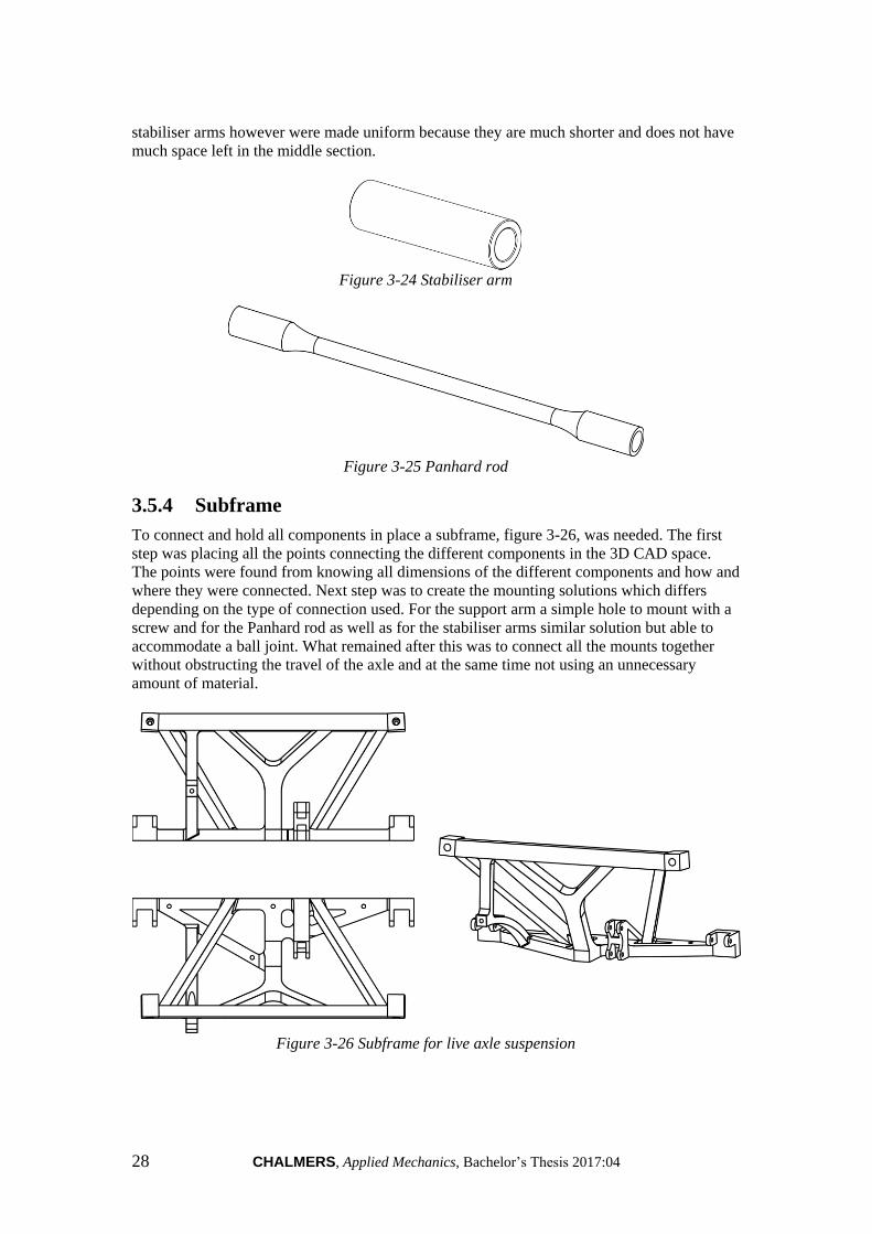
28 CHALMERS, Applied Mechanics, Bachelor’s Thesis 2017:04
stabiliser arms however were made uniform because they are much shorter and does not have
much space left in the middle section.
Figure 3-24 Stabiliser arm
Figure 3-25 Panhard rod
3.5.4 Subframe
To connect and hold all components in place a subframe, figure 3-26, was needed. The first
step was placing all the points connecting the different components in the 3D CAD space.
The points were found from knowing all dimensions of the different components and how and
where they were connected. Next step was to create the mounting solutions which differs
depending on the type of connection used. For the support arm a simple hole to mount with a
screw and for the Panhard rod as well as for the stabiliser arms similar solution but able to
accommodate a ball joint. What remained after this was to connect all the mounts together
without obstructing the travel of the axle and at the same time not using an unnecessary
amount of material.
Figure 3-26 Subframe for live axle suspension

CHALMERS, Applied Mechanics, Bachelor’s Thesis 2017:04 29
3.5.5 Assembling
When assembling the suspension the screws were implemented as axial constraints so the
only allowed movements were along the axis and rotation around it. This was limiting in the
sense that the bushings which could be mounted in these position normally are not
compensated for at all. The compensations made with conical holes as well as larger holes
would not help either. For ball joints a distance constraint was set so that the rotation
possibilities were kept. This solutions allows more than the joints do but when the movements
are normal it should give a fair representation. The final assembly can be seen as a render in
figure 3-27.
Figure 3-27 Render of live axle suspension
3.6 Chassis
To get the correct kinematics out of the front and rear suspensions when applying force they
had to be linked together. This was naturally done with a chassis, to which the subframes
were attached. It was important that the chassis were stiff to not affect the behavior of the
suspensions in a way that conflicts with the kinematics, as this is desired in this model. The main target was to fit the chassis to the wheelbase and the subframes. The wheelbase was
a given value at 2735
5 = 547 𝑚𝑚 and for the subframes it was just a matter of fitting to their
different designs. This was done by taking the measurements of the different angles and
points and transfer them to the chassis. Matching holes were made to allow for a firm fitment
between the parts. One of the requirements from the task was to develop two different chassis to get all the
different combinations and have them working at the same time. Because of the similarity of
the two front suspensions, MacPherson and double wishbone, it was chosen that those were
the ones that were going to be interchangeable. The other two, trailing arm and live axle, were
permanently attached to the rear of the two chassis, which can be viewed in figure 3-28 and 3-
29.
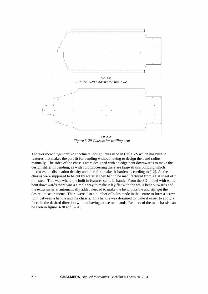
30 CHALMERS, Applied Mechanics, Bachelor’s Thesis 2017:04
Figure 3-28 Chassis for live axle
Figure 3-29 Chassis for trailing arm
The workbench “generative sheetmetal design” was used in Catia V5 which has built in
features that makes the part fit for bending without having to design the bend radius
manually. The sides of the chassis were designed with an edge bent downwards to make the
design stiffer in bending, as with cold processing there are large strains building which
increases the dislocation density and therefore makes it harden, according to [12]. As the
chassis were supposed to be cut by waterjet they had to be manufactured from a flat sheet of 2
mm steel. This was where the built in features came in handy. From the 3D-model with walls
bent downwards there was a simple way to make it lay flat with the walls bent outwards and
the extra material automatically added needed to make the bend possible and still get the
desired measurements. There were also a number of holes made in the centre to form a screw
joint between a handle and the chassis. This handle was designed to make it easier to apply a
force in the desired direction without having to use two hands. Renders of the two chassis can
be seen in figure 3-30 and 3-31.
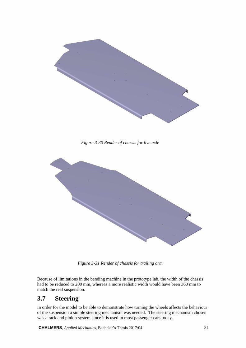
CHALMERS, Applied Mechanics, Bachelor’s Thesis 2017:04 31
Figure 3-30 Render of chassis for live axle
Figure 3-31 Render of chassis for trailing arm
Because of limitations in the bending machine in the prototype lab, the width of the chassis
had to be reduced to 200 mm, whereas a more realistic width would have been 360 mm to
match the real suspension.
3.7 Steering
In order for the model to be able to demonstrate how turning the wheels affects the behaviour
of the suspension a simple steering mechanism was needed. The steering mechanism chosen
was a rack and pinion system since it is used in most passenger cars today.
32 CHALMERS, Applied Mechanics, Bachelor’s Thesis 2017:04
3.7.1 Subframe
Figure 3-32 Steering subframe
The starting point for the design engineering process of the steering linkage was designing the
subframe that would hold all the components in place. Because the suspension models are
modular, it was important to ensure that the steering subframe could be mounted on either of
the two front suspension modules. This was done by deciding on a flat profile for the front
and underside that could be positioned behind the suspension subframes on a small platform
sticking out from the back of the suspension subframes. The subframe was designed to have
two y-shaped stands with mounting brackets on top to support the steering rack and allow the
steering rack to slide from side to side. To support the steering shaft and pinion, three
supporting towers with holes for the steering rack and pinion axle to pass through. Because
the rack and pinion are positioned horizontally but the steering rack usually is not, a universal
joint was needed to transfer the rotation of the steering rack to the pinion. The U-joint consists
of two so called yokes which are connected by a cross which allows rotation in in any
direction. The U-joint was designed to be as small as possible but still be able to clamp onto a
3 mm shaft. The U-joints turned out to be far too small for the available 3D printers but unlike the rack
and pinion the U-joints were not parametrically designed, so making them larger would take a
lot of time. Because of the difficulty of redesigning them it was decided to order off-the-shelf
U-joints to save time and ensure proper operation. The available U-joints were much larger
than the designed ones and that caused clearance issues between the outer edge of the U-joint
and the rear support tower. To address this the rear support tower was made one millimeter
slimmer. During test assembly it was discovered that the pinion axle did not have enough support
which caused it to twist along the y- and z-axis and reducing the precision and feel in the
steering. The twisting was eliminated by adding a third support tower in front of the steering
rack at the very front of the steering subframe. The finished design of the steering subframe
can be seen in figure 3-32.

CHALMERS, Applied Mechanics, Bachelor’s Thesis 2017:04 33
3.7.2 Steering Rack and Pinion Gear
Figure 3-33 Steering rack for double wishbone suspension
To transfer the rotational movement of the steering wheel to the wheels of the car a rack and
pinion is needed. The rack for the double wishbone suspension can be seen in figure 3-33.
The pinion was designed by first setting the module to 0.5 mm and the number of teeth to 14.
This gave a good compromise between being printable but at the same time not resulting in a
gear ratio that is too high compared to the real car. The pressure angle was chosen to be 20
degrees as this is the most common pressure angle in gears. These values were the only ones
needed to calculate the remaining dimensions of the gear. The following equations were used
to design the pinion. 𝑁𝑢𝑚𝑏𝑒𝑟 𝑜𝑓 𝑡𝑒𝑒𝑡ℎ 𝑧 = 14
𝑀𝑜𝑑𝑢𝑙𝑒 𝑚 = 0.5 𝑚𝑚
𝑃𝑖𝑡𝑐ℎ 𝑐𝑖𝑟𝑐𝑙𝑒 𝑟𝑎𝑑𝑖𝑢𝑠 = 𝑚𝑧
2= 3.5 𝑚𝑚
𝐴𝑑𝑑𝑒𝑛𝑑𝑢𝑚 𝑐𝑖𝑟𝑐𝑙𝑒 𝑟𝑎𝑑𝑖𝑢𝑠 = 𝑚𝑧
2+ 𝑚 = 4 𝑚𝑚
𝐷𝑒𝑑𝑒𝑛𝑑𝑢𝑚 𝑐𝑖𝑟𝑐𝑙𝑒 𝑟𝑎𝑑𝑖𝑢𝑠 = 𝑚𝑧
2− 1.25𝑚 = 2.875 𝑚𝑚
The rack was based on the Swedish standard SMS 296 [13] which can be seen in figure 3-34.
It has a pressure angle of 20 degrees which matches that of the gear that was previously
designed. In order for two gears to mesh properly, they need to have the same pressure angle
and module so the rack was given the same module and pressure angle as the pinion. The
minimum length of the steering rack was given by the requirement to allow for 16.5 mm of
rack travel to either side. This meant that the geared part of the rack had to be at least 33.0
mm long. The distance between the two inner ball joints was given by the hardpoints and was
148 mm. The total length of the steering rack was required to allow for the inner ball joints to
be mounted 148 mm apart. The height of the steering rack was not a given dimension so it
could be decided freely. It was set to 4.5 mm as this was considered to be thick enough since
the steering rack would not bear any load in the z-direction. The position of the ball joints in
the z-direction is critical and is given by the hardpoints. This position had to be matched by
adjusting the z-position of the steering subframe relative to the suspension subframe. The
width of the steering rack was also unrestricted but was chosen to be 7 mm to give sufficient
margin for the holes for the ball joint mounting screws.

34 CHALMERS, Applied Mechanics, Bachelor’s Thesis 2017:04
Figure 3-34 SMS 296 Reference Profile
The pinion and rack need to be mounted with the correct spacing to make sure that they mesh
correctly. This distance is given by the formula 𝑎 = 𝐷𝑜2 +𝐷𝑜1
2[14] where Do1 is the pitch
circle of the pinion and Do2 is the distance from the base of the steering rack to the pitch line
which can be seen in figure 3-35.
Figure 3-35 Axle distance for rack and pinion
Since the model with MacPherson struts also has a differential that occupies most of the room
where the steering rack normally would be mounted the steering rack had to be moved along
the y-axis to clear the differential housing. The problem with moving the steering rack is that
when the inner tie rod ball joint moves it changes the steering dynamics i.e bump steer and
ackerman. To avoid this, the steering rack was designed to have “arms” extending forward so
that the inner tie rod ball joints still can be mounted in the specified locations (See figure 3-
36). Changing the length of these arms does not affect the steering geometry so it can be
adapted to fit different suspensions.
CHALMERS, Applied Mechanics, Bachelor’s Thesis 2017:04 35
Figure 3-36 MacPherson steering rack
After the first iteration of the rack and pinion was 3D printed it was clear that that the 3D
printer was not able to print such fine teeth as those on the rack and pinion. To overcome this
the number of teeth on the pinion was reduced from 14 to 10 and the module was increased
from 0.5 to 0.8 mm on both the rack and pinion to make the teeth larger.
3.7.3 Pressure Plate
Figure 3-37 Pressure plate viewed from the bottom
Because of the limited accuracy of 3D printing and the tight tolerances needed for the rack
and pinion to mesh properly it was decided to make the rack spring loaded to minimize the
risk of the gears slipping. This was done by designing a pressure plate to be placed under the
steering rack. To assure that the pressure plate would not move in any other direction than up
or down, guiding pins were added to the underside of the pressure plate. Holes for the guiding
pins were made in the corresponding locations on the steering subframe. The steering
subframe did also get holes where two small compression springs could be placed and push
up on the pressure plate. When the steering was assembled on the double wishbone
suspension the steering rack would not move smoothly and the problem was derived to the
spring mechanism pressing up too hard on the rack causing the rack and pinion to bind. When
the steering was tested without the springs and pressure plate it worked perfectly so the spring
mechanism was abandoned for the double wishbone suspension. It did however work on the
MacPherson suspension. The finished design of the pressure plate can be seen in figure 3-37.

36 CHALMERS, Applied Mechanics, Bachelor’s Thesis 2017:04
3.7.4 Steering Wheel
Figure 3-38 Steering wheel
To make it easier to turn the wheels a steering wheel was needed. The steering wheel was
designed with a sporty look to fit the characteristics of the suspension models. It has an
outside diameter of 67 mm which equates to 335 mm in full scale and is close to a typical
steering wheel diameter. A hole was made in the rear of the steering wheel for the 4 mm
steering shaft to slide into. To secure the steering wheel to the steering shaft a hole for a 3 mm
screw was made perpendicular to the steering shaft. The steering wheel can be seen in figure
3-38.
3.8 Tyre and Rim
To be able to see the different angles during steering and travel of the suspension wheels were
needed. The dimensions of the tyre and rim was based on a common 19 inch wheel with tyre
dimensions 235/50 R19 and rim dimensions 8.0x19x52. These dimensions have been
converted to the scale 1:5 to fit the model. The number 235 is the value of the width of the
tyre in millimeter and 50 gives the proportion of the height of the tyre based on the width of
the tyre. So the height of the tyre is 50 percent of 235 mm, which is 117.5 mm. R19 stands for
the size of the tyre which is 19 inch in diameter. In the following designation for the rim
8.0x19x52 the first number indicates the width of the rim, in this case 8 inch. The second
number indicates the diameter of the rim and is 19 inch. And the third number indicates where
the mounting point of the rim is. Wheel centre (offset 52 mm) is the point in the centre of the
rim where it will be attached to on the hub. This point positions the wheel in y-direction to
give the intended steering and suspension geometry. Rim and tyre can be viewed in figure 3-
39.

CHALMERS, Applied Mechanics, Bachelor’s Thesis 2017:04 37
Figure 3-39 To the left is the rim and to the right the tyre
During the design phase parameters as strength and possibility to 3D print was considered. A
redesign of the centerpiece of the rim had to be made to enable mounting of the drive shaft
and get drive to the wheel. A standard pattern has been done on the tyre to symbolise and get
a realistic feeling. The tyre and tre pattern was not in any way tested for grip it was only
tested to work as a standing model. To save time and get as few different components as
possible the design of the tyre was made symmetrical to enable usage on both sides. To make
the rim more convenient to print and eliminate a lot of support material a 45 degree angle was
made on the inside of the rims sharp edges that keeps the tyre from sliding off. This
modification was also made on all sharp edges on the tyre to improve the surface of the
printed tyre. When printing in a softer and elastic plastic material the 3D printer has a hard
time printing sharp edges because it rips loose the threads it is making. A major improvement
of the surface of the tyre was seen when the modification was applied. The final wheel can be
seen as a render in figure 3-40.
Figure 3-40 Render of tyre and rim mounted together
3.9 Simulation
The simulations carried out were mainly done in Catia V5. For simple geometry changes it is
beneficial to use Catia V5 and easy to access since it is the workbench where the majority of
every suspension and detail has been designed. Through Catia V5, clashes of assemblies can
be detected and end point values for suspension travel can be verified.

38 CHALMERS, Applied Mechanics, Bachelor’s Thesis 2017:04
The shortcoming of Catia V5 is that it is not effective for analysing more than one data point.
To solve this issue a software called “Optimum Kinematics” was used and with this software
simulations can be done for different scenarios. By importing the hardpoints of the suspension
and defining wheels and static characteristics a simulation can be made. Simulations can then
be done for heave (bump), steering or roll. Defining a scenario, e.g. heave, the software will
simulate the travel of the chassis vertically to the limitations defined by the user. What is
important here is that when the chassis travels a given amount of millimeters upwards it
represents the suspension traveling downwards. By doing this appropriate graphs could be
drawn for camber gain and bump steer. Unfortunately, the software did not support the rear
suspensions due to the limitations of the licens. Because of this, simulations have only been
done for the two front suspensions.
3.10 Manufacturing Parts
3.10.1 3D Printing
Before starting the printer, files from Catia V5 were saved as stl files and prepared in the
software “Simplified 3D” or “Makerbot Print”. The program inserted supports and rafts to the
product if needed and converted it into a file format that could be read by the printer. The
desired filament material and colour was loaded in the 3D printer and preheated to the
working temperature. The 3D printers used were a Makerbot Replicator 2, a Makerbot Z18
and a ZYYX+ and are located in the course lab at Chalmers. In figure 3-41 the Makerbot
replicator 2 can be seen and the ZYYX+ in figure 3-42.
When the previously described steps were finished the printer was started and left to print the
desired part. It could take anywhere between 15 minutes and 48 hours depending on the size
of the parts and the amount of plastic needed. Common problems that could occur when 3D
printing were filament rolls that got stuck, lack of filament on the roll which made the print
cancel, filament that got stuck in the extruder and nozzle, the part coming loose from the
build plate it is printing on, defects because of loose supports and the extruder getting out of
position.
3D printing is an iterative process where you have to test many times to succeed and get high
quality products. Every part is unique and you never know if the print will work out as
intended. Depending on the size of the part different 3D printers need be used.
The material used in the printers is PLA plastic and is preferably used instead of ABS plastic
which is toxic. For the tyres NinjaFlex TPE plastic is used to get the softness needed to
imitate a real tyre.
Figure 3-41 Makerbot replicator 2 during print
CHALMERS, Applied Mechanics, Bachelor’s Thesis 2017:04 39
Figure 3-42 ZYYX+ during print
3.10.2 Machining Anti-roll Bar
From the anti-roll bars designed in Catia V5 drawings were printed and brought down to the
workshop of Chalmers. They were based on a 2 mm silver steel rod that was bent to the
desired shapes. The anti-roll bar consist of three parts: two rods and one cylinder with stop
screws in it. The cylinder with the stop screws is used to link the rods together. When
unscrewing one of the stop screws, they disconnect from each other and the anti-roll bar is out
of function.
3.10.3 Machining Chassis
Based on Catia V5 files the chassis with its holes were water jetted from a two millimeter
steel plate in the workshop of Chalmers. All sharp edges of the plate were rounded off to
improve the mobility of the vehicle without causing any wounds. The side edges were bent 90
degrees to get easy access to the joystick and get good stability of the body structure.
3.10.4 Assembling/Post Processing
When the parts were manufactured they were assembled with bolts and screws. Choice of
method is based on that some parts are supposed to be interchangeable and some not. As the
plastic shrinks a few percent, around 3-5% depending of the size of the part and which printer
that was used, most of the holes had to be drilled up to the needed dimension. This was
especially a problem with mounting the subframes to the chassis as the precision of the
waterjet is almost perfect, which the 3D printers are not.

40 CHALMERS, Applied Mechanics, Bachelor’s Thesis 2017:04
4 Chapter Four – Results
In this chapter all results will be presented and all measured values can be found in Appendix
B.
4.1 Static
Static photos of the entire models can be seen in figure 4-1 and 4-2.
Figure 4-1 Chassis with trailing arm and double wishbone mounted
Figure 4-2 Chassis with live axle and MacPherson mounted

CHALMERS, Applied Mechanics, Bachelor’s Thesis 2017:04 41
4.1.1 MacPherson
Figure 4-3 Picture of MacPherson suspension
The result of the MacPherson strut suspension model in scale 1:5 is shown in figure 4-3. A
colour code with two different colours keeps the components of the suspension apart, which
can be read in table 1. The control arm is coloured red and both the upright and subframe is
coloured black and can be seen in figure 4-3. A black steering rack can be found in the rear
centre of the subframe and enables steering on the suspension from the attached steering
wheel. At the rear of the subframe a knob is found that enables propulsion on both front
wheels. On the model there are two coilover dampers, one anti-roll bar and two 12 mm wheel
bearings on each upright. To enable steering and travel two ball joints links each upright and
steering rack together. The joint point for the anti-roll bar is located on the contral arm. One
ball joint links the upright and control arm together to get the right movement. The upper part
of the coilover dampers are mounted together with the subframe with a ball joint that enables
the sought after movement.
Table 1 Colour and corresponding part - MacPherson
Colour Part
Black Upright
Red Lower control arm
Black Subframe

42 CHALMERS, Applied Mechanics, Bachelor’s Thesis 2017:04
Figure 4-4 Ride height measurement
In figure 4-4 the ride height is measured to 40.8 mm and in figure 4-5 the track width can be
seen to be 318 mm. The camber can be seen in figure 4-6 in static kerb +2 position of the
model and is -0.5 degrees.
Figure 4-5 Measurement of track width

CHALMERS, Applied Mechanics, Bachelor’s Thesis 2017:04 43
Figure 4-6 Measurement of static camber
4.1.2 Double Wishbone
Figure 4-7 Picture of double wishbone suspension
The double wishbone suspension can be seen in figure 4-7. It consists of four colour coded
parts, two coilover damper and a detachable anti-roll bar. The colour coded parts and their
respective colour can be seen in table 2. The upright is black and it carries two 12 mm wheel
bearings that are separated in the y-direction and gives stability to the wheel axis. The fixation
of the upright is handled by two ball joints that enables both travel and steering. The ball
joints are placed along the kingpin axis with a spread of 57.5 mm. Two wishbones are
44 CHALMERS, Applied Mechanics, Bachelor’s Thesis 2017:04
connected to the upright via the ball joints. The upper wishbone is green, it holds the
connection to the anti-roll bar, and measures 68 mm in the y-direction between its hardpoints.
The lower wishbone which is red, holds the connection to the coilover damper and measures
80 mm in the y-direction between its hardpoints. Both wishbones are symmetric around the
wheel axis and has two attachment points in the subframe to handle forces in the x-direction.
The fourth part is the blue subframe that holds attachments for both wishbones, the coilover
damper and steering rack. The fifth and last main part is the black steering rack, it is fitted
behind the wheel centre in the subframe and is linked to the uprights via ball joint mounted tie
rods.
Table 2 Colour and corresponding part – Double wishbone
Colour Part
Black Upright
Red Lower wishbone
Green Upper wishbone
Subframe Blue
The following static results were measured on the scale model in kerb +2:
Figure 4-8 Ride height on double wishbone suspension
The ride height in the design position is measured to 28.2 mm from the lowest part of the
chassis and can be seen in figure 4-8.

CHALMERS, Applied Mechanics, Bachelor’s Thesis 2017:04 45
Figure 4-9 Track width on double wishbone suspension
The track width is 316.2 mm as seen in figure 4-9.
Figure 4-10 Camber angle on double wishbone suspension
As shown in figure 4-10 the camber angle in the design position is -0.5 degrees.
Final static kerb +2 dimensions of the double wishbone design are listed below:
Ride height: 28.5 mm
Track: 317.7 mm
Camber: -0.5 degrees
Caster: 0 degrees
Toe: 0 degrees
Roll centre: 12 mm
Ground offset: 2 mm
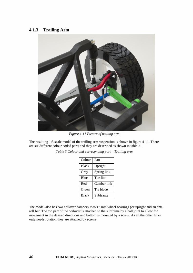
46 CHALMERS, Applied Mechanics, Bachelor’s Thesis 2017:04
4.1.3 Trailing Arm
Figure 4-11 Picture of trailing arm
The resulting 1:5 scale model of the trailing arm suspension is shown in figure 4-11. There
are six different colour coded parts and they are described as shown in table 3.
Table 3 Colour and correspnding part – Trailing arm
Colour Part
Black Upright
Grey Spring link
Blue Toe link
Red Camber link
Green Tie blade
Black Subframe
The model also has two coilover dampers, two 12 mm wheel bearings per upright and an anti-
roll bar. The top part of the coilover is attached to the subframe by a ball joint to allow for
movement in the desired directions and bottom is mounted by a screw. As all the other links
only needs rotation they are attached by screws.

CHALMERS, Applied Mechanics, Bachelor’s Thesis 2017:04 47
Figure 4-12 Ride height on trailing arm suspension
The resulting ride height in design position is measured to 37.2 mm from the lowest part of
the chassis at the rear to the ground, figure 4-12.
Figure 4-13 Camber angle in design position on trailing arm suspension
The camber angle is -0.1 degrees for the wheel in the design position nad can be seen in
figure 4-13.

48 CHALMERS, Applied Mechanics, Bachelor’s Thesis 2017:04
Figure 4-14 Track width on trailing arm suspension
The track width is measured to 315.4 mm
4.1.4 Live Axle
Figure 4-15 Picture of live axle suspension
In figure 4-15 the live axle suspension model in scale 1:5 is shown. The 3D printed colour
coded suspension parts and corresponding colours can be found in table 4. Except for those
parts it also consists of two coilover dampers with 3D printed extensions. To keep the wheels
in place two bearing separated in the y-direction by a spacer is placed on each end of the axle.

CHALMERS, Applied Mechanics, Bachelor’s Thesis 2017:04 49
Table 4 Colour and corresponding part – Live axle
Colour Part
Black Axle
White Support arms + complementary piece
Grey Panhard rod
Red Stabiliser bars
Black Subframe
Figure 4-16 Ride height on live axle
The ride height, which can be seen in figure 4-16, is in the design position 48.3 mm measured
from the lowest point on the chassis to the ground where the wheels touch.
Figure 4-17 Track width of live axle
The track width is measured to 319.5 mm and can be seen in figure 4-17.

50 CHALMERS, Applied Mechanics, Bachelor’s Thesis 2017:04
4.2 Kinematics
All graphs in this chapter shows values for a full scale model as these values are more
familiar and useful in comparison.
4.2.1 MacPherson
The first graph, figure 4-18 shows the camber gain when the suspension travels from 80 mm
jounce to 110 mm rebound, which can be seen on the x-axis. On the y-axis the degrees of
camber is shown and what can be noticed here is that the negative camber gain reaches its
minimum at -1.2 degrees and then slowly increase to a final -1.0 degrees at 80 mm. In the
rebound motion of the wheel the camber reaches a value of 1.3 degrees
Figure 4-18 Camber gain, y-axis shows degrees and the x-axis shows travel in mm
Regarding the bump steer for MacPherson, seen in figure 4-19, the same x-axis as in figure 4-
18 is used with the degrees of steering on the y-axis. As the wheels move up to its peak of 80
mm the steer angle is -3.3 degrees compared to the when the wheel moves down to 110 mm
and reaches a value of 0.5 degrees.

CHALMERS, Applied Mechanics, Bachelor’s Thesis 2017:04 51
Figure 4-19 Graph of bump steer
The following kinematic results were measured on the scale model: The wheel travel is 11.8 mm rebound and 8.6 mm jounce with a total wheel travel of
20.4 mm.
The camber gain is 1.3 degrees at full rebound and 0 degrees at full jounce -0.9.
The maximum steering angle is 36.3 degrees for the inner wheel and 25.7 degrees for
the outer wheel. Ackerman percentage is 28.3 % at full steering angle.
Figure 4-20 Wheel travel MacPherson
In figure 4-20 the travel of the wheel can be seen during full jounce to be 8.6 mm and during
full rebound to be 11.8 mm.

52 CHALMERS, Applied Mechanics, Bachelor’s Thesis 2017:04
Figure 4-21 Camber angle in full jounce and full rebound
The camber angle in full jounce is -0.9 degrees and full rebound is 1.3 degrees, which can be
seen in figure 4-21.
Figure 4-22 Showing of steering angle on outer and inner wheel
The steering angle on the inner wheel is 36.3 degrees and 25.7 degrees on the outer wheel
when having full steer angle, which can be seen in figure 4-22.
4.2.2 Double Wishbone
Camber gain can be seen in figure 4-23. The x-axis shows the motion of the chassis and the y-
axis the camber angle. When raising the chassis 110 mm the wheel travels -110 mm and the
camber angle changes to 1.4 degrees. Positive wheel travel of 80 mm results in -2.4 degrees
camber. The camber change is not symmetric around the design position, positive wheel
travel results in greater camber change than negative wheel travel.
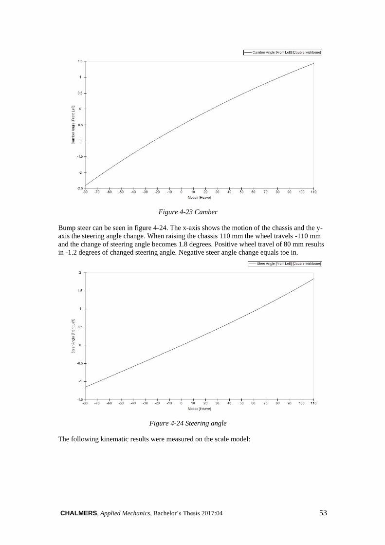
CHALMERS, Applied Mechanics, Bachelor’s Thesis 2017:04 53
Figure 4-23 Camber
Bump steer can be seen in figure 4-24. The x-axis shows the motion of the chassis and the y-
axis the steering angle change. When raising the chassis 110 mm the wheel travels -110 mm
and the change of steering angle becomes 1.8 degrees. Positive wheel travel of 80 mm results
in -1.2 degrees of changed steering angle. Negative steer angle change equals toe in.
Figure 4-24 Steering angle
The following kinematic results were measured on the scale model:
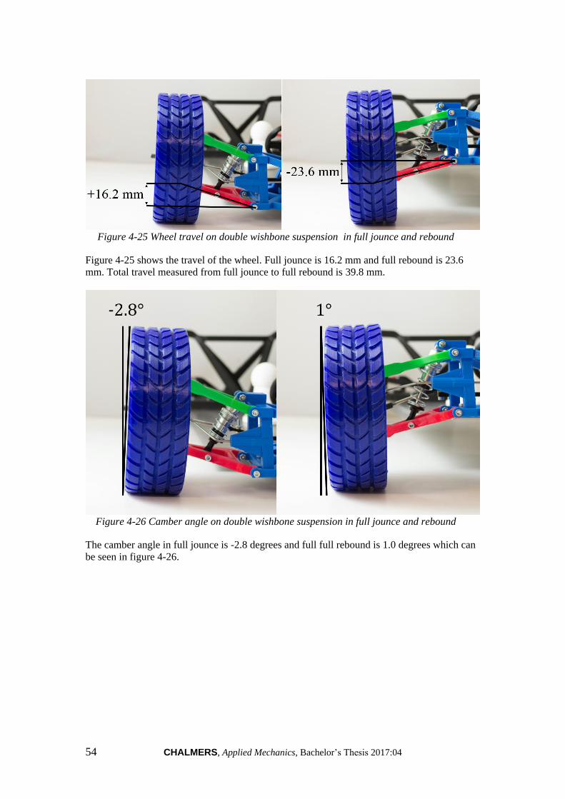
54 CHALMERS, Applied Mechanics, Bachelor’s Thesis 2017:04
Figure 4-25 Wheel travel on double wishbone suspension in full jounce and rebound
Figure 4-25 shows the travel of the wheel. Full jounce is 16.2 mm and full rebound is 23.6
mm. Total travel measured from full jounce to full rebound is 39.8 mm.
Figure 4-26 Camber angle on double wishbone suspension in full jounce and rebound
The camber angle in full jounce is -2.8 degrees and full full rebound is 1.0 degrees which can
be seen in figure 4-26.

CHALMERS, Applied Mechanics, Bachelor’s Thesis 2017:04 55
Figure 4-27 Steering angle on double wishbone suspension
The steering angle on the inner wheel is 44.8 degrees and 31.3 degrees on the outer wheel
when the steering is at full lock. The angles can be seen in figure 4-27. Ackerman percentage
is 31.1% at full steering angle.
4.2.3 Trailing Arm
As there are no softwares available to calculate the exact curves of the kinematics it is instead
measured by hand and evaluated by its ability to visualize the correct movement.
Figure 4-28 Wheel travel shown in full jounce and full rebound
The suspension has a wheel travel of 19.4 mm at full rebound and 17.6 mm at full jounce
which gives a total of 37 mm wheel travel, to be seen in figure 4-28.
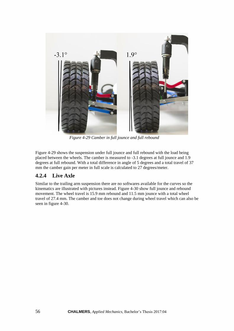
56 CHALMERS, Applied Mechanics, Bachelor’s Thesis 2017:04
Figure 4-29 Camber in full jounce and full rebound
Figure 4-29 shows the suspension under full jounce and full rebound with the load being
placed between the wheels. The camber is measured to -3.1 degrees at full jounce and 1.9
degrees at full rebound. With a total difference in angle of 5 degrees and a total travel of 37
mm the camber gain per meter in full scale is calculated to 27 degrees/meter.
4.2.4 Live Axle
Similar to the trailing arm suspension there are no softwares available for the curves so the
kinematics are illustrated with pictures instead. Figure 4-30 show full jounce and rebound
movement. The wheel travel is 15.9 mm rebound and 11.5 mm jounce with a total wheel
travel of 27.4 mm. The camber and toe does not change during wheel travel which can also be
seen in figure 4-30.

CHALMERS, Applied Mechanics, Bachelor’s Thesis 2017:04 57
Figure 4-30 Full jounce and full rebound movement
58 CHALMERS, Applied Mechanics, Bachelor’s Thesis 2017:04
5 Conclusions and Discussion
5.1 Conclusions and Fulfilment of Deliverables
All of the following objectives of this thesis have been met:
A front MacPherson suspension model in scale 1:5 with differential and steering
A front Double Wishbone suspension model in scale 1:5 with steering
A rear Trailing arm suspension model in scale 1:5
A rear Live axle suspension model in scale 1:5 without anti-roll bar
Two vehicle chassis with interchangeable front suspensions
The following conclusions apply on all models. The spring and anti-roll bar stiffness is not
properly scaled. Due to the lack of bushings the models have some play in the joints reducing
the accuracy of the movements. This results in inaccurate and varying values for camber, toe
etc. The stiffness of all parts is as expected not representative. Despite this the models have
good illustrative capability and are therefore well suited as educational material. It has been
very good for the understanding of suspension systems to work with the selected variants of
suspensions. Due to the volume of work with the variants the time has not allowed for solving
all details.
5.2 Future Work
Several areas can be improved to get a more realistic and correct model. Improvements such
as adding bushings to links and control arms to get a more realistic movement and feeling
should be done. This would reduce play in subframes and uprights. If bushings could be
added realistically a better understanding of how they work could be achieved since bushings
are moving and flexing. Enabling 3D printing in rubber will make it possible to implement
bump stops which are a crucial part of the suspension that is often hard to understand.
Redesigning the upper control arm on the double wishbone suspension so it can be moved
sideways to see how caster, camber and toe is affected. It can not be done on most normal
cars but it is preferable on the model to show how small movements of the control arm can
make major effect on the setting of a car. Another aspect is to further develop the spring
stiffness to better suit the scaled models.
By adding radio controlled propulsion and brakes it would be easier to simulate and show
how anti-squat/dive works and see the difference between shaft torque and torque from the
brakes and how it affects the vehicle. If the vehicle is radio controlled it will also be possible
to see how the anti-roll bar affects the roll, a natural movement of the suspension which can
be seen when going over rough terrain or obstacles. To get a better understanding of the
importance and the different characteristics of the suspensions a rig could be made to easily
demonstrate it. With the rig a systematic series of movement could be implemented and the
movement of the different suspensions can easily be seen. In the existing model the anti-roll
bar is too weak relative to the springs as it can not cope with lifting the opposite wheel and
needs to be modified and calculated to give the right stiffness. To improve even more a
change of material to spring steel would be preferable to get the right characteristics and
function of the anti-roll bar.
The tyres should be developed further to get a more realistic stiffness and better grip if the
models are to be radio controlled to enable the vehicle to roll, dive and squat correctly when
moving. The existing tyres have a honeycomb structure inside that gives the load carrying
capacity instead of air like a real tyre. A future development of the tyre stiffness can be made
to get a more realistic behavior when the tyre is loaded. If the tyres instead are to be air filled
a redesign of the rims is necessary to handle the pressure that will occur. Redesign of the rim
CHALMERS, Applied Mechanics, Bachelor’s Thesis 2017:04 59
would maybe be necessary if the vehicle would be radio controlled as large forces would
occur when jumping, going over bumps and similar. Existing rims are designed for a static
model where no large forces are applied. They may work for larger loads but field tests
should be carried out to see if they manage the forces. The resolution and infill of the 3D
printed rim is critical since it affects if the rim can stand large or nearly zero loads before
breaking. Adding steering limiters on the steering rack will make sure that the rim does not hit
the wishbone or the steering link hits the rim. This is needed to get the exact steering angle as
specified by the given data.
Creating graphs for trailing arm and live axle on its movement is advantageous to be able to
compare reality to the 1:5 model. By adding more graphs with different setups more
conclusions of how the vehicle acts can be made. For example different camber or caster and
their impact on the grip could be shown. This to link data to reality together and understand
what the parameters do.
To get an even better feeling of how the car and the suspension moves a removable body
could be added. This would show how the wheel moves up and down in the wheel well and
give a perspective of how much it moves. A body would also improve the visibility of roll if
the vehicle is moving. Another positive aspect is that it would better visualise how big the
wheel envelope, meaning the volume created by tracing the movement of the wheel as it
steers and travels, has to be to not get any interference.
5.3 Discussion
5.3.1 Plastic Shrinkage
Each part that is 3D printed has a shrinkage of 3-5% depending on which 3D printer that has
been used. This could be critical for some parts and for some parts not. After some test prints
knowledge was gained on how much components shrinks in each 3D printer and can be used
for future components. Knowledge in how holes should be dimensioned to fit different
standard screw sizes and similar. This to avoid drilling holes to make the screw fit. The
crucial part to avoid is to go through the solid layers and get to the hollowness. If this is done
a new part needs to be printed because the structural integrity of the hole will be lost. Even
though the knowledge of shrinkage the printers varied a lot and some parts still shrunk too
much.
5.3.2 Coilover Damper Mount Hardpoint
The suspensions have designs similar to real passenger cars, where especially the links and
uprights look like they would on a full scale model. As the subframes are designed on
freehand, they do not correspond to what the real subframes look like. One of the reasons,
which is mutual for all suspensions, is that the hardpoint where the coilover damper or strut
attaches to the subframe instead should be mounted to the body structure of the car. For
obvious reasons that can not be done as there was not supposed to be any body structures
manufactured. Regardless of the looks of the subframe, all hardpoints are downscaled and
positioned in the correct place which gives the same characteristic as the Chalmers
suspension.
5.3.3 Stiffness
In general it is hard to dimension the stiffness in the subframes, chassis, coilovers, struts and
anti-roll bars when applied on downscaled models. Furthermore it was not in the scope of the
project. When using off-the-shelf components the lack of detailed information makes
choosing the correct components difficult. The stiffness of the spring on RC components is
usually not specified more than as “soft”, “medium” or “hard” and therefore it is a gamble
when making the choice. When off-the-shelf components were to be ordered no information
about the chassis weight was known, so only approximations were made.

60 CHALMERS, Applied Mechanics, Bachelor’s Thesis 2017:04
It is hard to scale down the forces that occur on separate parts on a suspension in full scale.
This is because of the changes to other materials on the model. In this case the suspension
components are made of plastic which is much weaker than the steel normally used on the
full scale car. It is plausible to dimension bushings, springs and anti-roll bars through testing
and calculations. Each 3D printed component has different stiffness depending on the infill
and the resolution used for each part. When force is applied to get movement of the wheel the
3D printed components flex. To get every component to work perfectly and with the right
stiffness is a time consuming challenge. For manufacturing bushings no suitable material has
been found to get the right characteristics and stiffness. It is also a complex product to print,
especially when the bushings are so small on the downscaled model.
There is also an issue when a calculated length that the coilover dampers need to be can not
be matched because of limited types of RC car dampers available. The designed extenders are
an unwanted part of the suspensions, but also the most fitting solution to the two front
suspensions. The mounted components to MacPherson and double wishbone, have similar
stiffness but are of different lengths. These are much softer than those mounted on both of the
rear suspensions, trailing arm and live axle, which is an issue since that is not representative
of a setup on a real car. To get them to match the front better, the springs had to be cut down
and stretched to decrease the stiffness. Still there is a variation between the front and the rear
making it uneven and a future solution would be to order or manufacture springs of the
appropriate stiffness.
5.3.4 Anti-roll Bar
A silver steel, also known as high carbon steel, rod with a diameter of 2 mm is used for the
anti-roll bars on the model. As found when testing the models, it would be preferable to use a
larger diameter or treated silver steel rod so the anti-roll bar is stiffer relative to the springs to
get a better representation of the function. As of now the movement of one wheel during
bump gives almost no movement of the other wheel, which it should. No calculations were
made on the stiffness and the material that was available at Chalmers is what was used to
manufacture the anti-roll bars. If the stiffness of the original anti-roll bar was known it would
still be hard to dimension it for the model because of the use of a different material as
mentioned before. The function can still be shown but not as good as it is on real cars.
However, for educational purpose the anti-roll bar still shows enough to create a perception of
what the purpose is.
5.3.5 Play Between the Parts
As pointed out earlier the play in the attachments is necessary because the bushing function is
not in place and would not move without it. This comes with the disadvantage of a loss of
accuracy in the kinematics as the play gives no resistance or elasticity whereas the bushings
do. One example is that the double wishbone suspension changes its wheel settings just
depending on how it stands. In this project where there are many other things that affect the
result, such as the plastic warping and shrinking in the printer, it is considered being a suitable
simplification. The models still give a representative image of the full size suspensions.
Another downside of this is that the toe angle is very hard to secure with the loss of accuracy.
Because of the very small angle of toe for those suspensions with toe, e.g. MacPherson should
have 0.03 degrees of toe and with just a minor amount of play it quickly because hard to
measure a correct angle. Since the toe is hard to measure this also affects the possibility of
measuring bump steer. When measuring the bump steer the values cannot be secured to be
accurate because the steering rack bent when friction force was created between ground and
tyre after applying force in z-direction to the model. The combination of play and bent
steering rack made the bump steer result unusable. Therefore the decision was made to not
involve the bump steer in the result.

CHALMERS, Applied Mechanics, Bachelor’s Thesis 2017:04 61
5.3.6 Colour coding
All 3D printed components are colour coded which helps for a clear and easy visualisation
suitable for educational purposes as it can be seen from far away. For the most important parts
the more visible colours were chosen. The design of the parts also help towards the
visualisation and educational value as it is an open “skeleton” design with as few hidden parts
as possible, which makes all components clearly viewable. The drawback of that is a design
which could possibly be less resistant to large forces as there could be more material added if
the visibility was not a priority. Under normal conditions they work as intended.
5.3.7 MacPherson
A parameter that affects the design is the differential that is integrated in the centre of the
subframe. The design of the driveshafts is simplified compared to real driveshafts, but they
still fulfill their purpose of driving the wheels when the differential is turned. The driveshafts
are mounted to link the differential to the upright to enable propulsion. This is to simulate
propulsion on the MacPherson suspension. Other parts as control arms and uprights are more
similar to their full scale counterparts but with small modifications. These differences are
often done to simplify the product and enable it to be 3D printed. The anti-roll bar was also
simplified due to the problems with attaching it to the coilover damper. Because of this there
is hard to reassure that the properties of the anti-roll bar is correct but the same principle was
used to design it.
Since the differential requires an abnormal amount of space the packaging problem of the
steering rack has been an issue. The solution is clever but due to the weakness of the 3D
printed material the U-shaped steering rack is affected by a bending moment causing the
steering joints between the rack and the upright to clash with the subframe. A solution to this
would be to manufacture a stiffer steering rack with the design at hand. E.g. a steel rack
would withstand the moment much better. Another solution would be to design a u-shaped
support for the steering rack to ensure its position. Due to the steering not being assembled
until the very last phase of the project, these problems were not noted before it was too late to
make improvements. However, when giving full steering the inner wheel gives 36.3 degrees
and the outer wheel is 25.7 degrees. This is less than the design values that was given but it
still shows the function of the ackerman steering, which is desired.
The upright is also affected by the weakness of the material. The attachment of the coilover
damper to the upright is constructed to withstand as much of lateral forces as possible with
the limitations at hand. Unfortunately, the weakness of material forces the coilover to first
move laterally before moving in its correct direction. This causes the camber travel of the
wheel to not take the correct path and it differs to the calculated result. However, it does not
harm the end purpose of this model since the negative camber is increased with the weak
structure of the upright.
The ride height of the printed model is 40.8 mm and the given ride height of the full scaled
car is just above 200 mm and with the factor of 5 in downscaling the result is acceptable.
Similar results can be found when analyzing the track width that measured at 317.1 mm
compared to the design target of 318.1 mm. The travel of the wheels are 8.6 mm in jounce
compared to 11.8 mm in rebound of the measured model which is a total of 20.3 mm of
travel. The range should however be a factor of two larger and this is because of the shorter
coilover. A solution to this would be to find a better coilover damper and redesign the
subframe. When it comes to the static camber it was measured to -0.5 degrees compared to
the design goal of -0.9 degrees which met the goal fairly well. The camber gain travels from -
0.9 to 1.3 degrees which matches the goal value better than the static camber. Even though the
camber is not completly accurate the representation of camber is still there and it is possible
to explain the effect of it.

62 CHALMERS, Applied Mechanics, Bachelor’s Thesis 2017:04
5.3.8 Double Wishbone
The double wishbone suspension model unfortunately did not get the correct colour of the
subframe, it is blue instead of black. The functionality is still the same but compared to the
other suspensions it differs in colour coding which can be misleading. This is because of
printing problem and lack of material.
The suspension was designed for 21 degrees of camber-gain/meter travel, as it would have in
full scale which is a more recognizable value. When calculating the hardpoints that affected
the camber gain the measurements were set in integer millimeter to get easy manageable
numbers. This made the final design camber gain 20.2 degrees/meter. The measured camber
gain on the model was calculated between full jounce and rebound, it resulted in 20.16
degrees/meter which is within the tolerance and more than good enough. Therefore no re
engineering was needed. The static camber on the model was designed as -0.5 degrees and
measured to -0.52 which is a good result. The camber results was overall better than expected
and could be a coincidence when looking at the overall performance of the ball joints and
joints.
When the hardpoints were tuned for the correct bump steer there were some difficulties to get
the numbers to add up. Because of this, the bump steer was made larger as it only has a
positive impact on the ability to visualise the bump steer. The final design result of 15.7
degrees/meter travel was in the upper span of the tolerance region but according to the group
better than the exact requirement for visualisation reasons. The same principle was utilized
during the ackermann design, the benchmark values are 10-20% and the value on the model is
15.2% at 20 degrees steer angle for the inner wheel which is over the minimum and enables
good visualisation. The ackermann at 20 degrees steering angle on the inner wheel was not
possible to calculate accurate due to play in the steering. The ackermann at full steer angle
was calculated to 31.1%. The values on the actual model are not entirely correct but they are
large enough to illustrate the ackermann steering geometry.
The amount of jounce and rebound is more than in the specification due to intentionally
rounded up values, but the ratio between jounce and rebound is correct. In total the movement
of the wheel centre on the model is 4.6% larger than the total downscaled travel given from
the task. Having more total travel makes visualisation easier because the change of angles is
bigger in the end positions. The extra 4.6% of travel is therefore considered as positive for
the task of the model's purpose. The ride height did not have a requirement, it was therefore
developed during the whole process with the aim of a lower front then rear. The final ride
height on the model, 28.2 mm is at the smallest but it gives a lover front and is therefore
considered as good.
The measurement that is most affected by the shrinkage of the plastic is of course the one that
involves most stretch of parts, the track width. It was designed to be 317.7 mm but was
measured to 316.2 mm. It was expected but could have been avoided by compensating for the
shrinkage.
5.3.9 Trailing Arm
One specific design feature that differs from the others is that the tie blade had to be attached
to the subframe instead of the body, where it should be. This gives an even larger and less
representative subframe. As long as the spectator is aware of this it does not affect the
understanding of the functionality of a trailing arm suspension.
The rear ride height of the Chalmers suspension is said to be 200 mm. In scale 1:5 this equals
to 40 mm. With the model in design mode the height is measured to 37.2 mm from the lowest
CHALMERS, Applied Mechanics, Bachelor’s Thesis 2017:04 63
part of the chassis at the rear to the ground. Since the chassis only purpose in this case is to be
a rigid connection between the front and rear suspensions, this was made to have an
approximately correct ride height and is for this reason an acceptable value.
The travel specified for the Chalmers MacPherson suspension at the wheel is 38 mm and as
the Chalmers trailing arm did not have that data specified that was also used when designing
this suspension. Out of the 38 mm, 16.3 mm is jounce and 21.7 mm is rebound. The coilover
used in the scale model has a travel of 33.3 mm. Because of the coilover being mounted
further inwards on the spring link, which acts as a lever, the gearing gives a travel of 37 mm
at the wheel, which is acceptable given the conditions. The jounce is measured to 17.6 mm
and the rebound 19.4 mm. In Catia V5, the proportions between these values were the same as
in the Chalmers MacPherson suspension. As there are no precision tools available to take
these kind of measurements that could be the cause of the offset or otherwise because of the
3D printer.
The toe angle given by the Chalmers trailing arm suspension is 0.1 degrees inwards in design
mode. Because of the precision of the 3D printers used, the rim and tyre varies very much
under a revolution causing the toe to, at a certain position, be a factor 10 larger than the
design value. As of this, the decision was made to not involve this result since it would not
add value to the report.
A negative camber of -1 degree is specified and the measured one is -0.1 degree. This suffers
from the same problem as the toe angle and could be fixed with a higher precision printer or
of the self components. However it is hard to find the right tyre and rim as of the specified
dimensions and design. As there is no data specified on the camber gain during rebound and
jounce, the result is compared to the given value of the double wishbone. It is 21
degrees/meter in full scale and the measured value is 27 degrees/meter. How the camber gain
of a double wishbone suspension relates to a trailing arm suspension is unknown, but there
are in this case now drawbacks with a larger value as this only gives a better visualization.
The comparison is also a bit unreliable as the given value is in a linear range close to the
design position and the calculated one is for the full travel of the suspension.
The track width specified from the Chalmers suspension is 1586.4 mm or 317.3 mm in 1:5
scale. From the measurement taken the track width is 315.4 which aligns very well with the
theoretical measure. The difference of about 2 mm comes from the already mentioned
problem of the printed parts shrinking a few percents during cooling.
5.3.10 Live Axle
When applying forces to the wheels fairly realistic movement from the axle and links can be
seen. One of the reason the movement is not fully realistic is because the suspension model is
based on pictures and not hardpoints for an actual suspension. Because of this the stabiliser
arms are not fully functional and only one can be mounted normally. When the other one is
mounted it is under strain resulting in impaired movements. Even though these problems are
there the base movement of the suspension is correct meaning it is still illustrative.
Another issue is that the axle stands too far to one side. This can be because of the Panhard
rod being too short in combination with the coilover damper getting too long with the
mounted extensions. The coilover damper and mount extension causes other problems as
well. For one the wheel travel is too short and the ride height is too high which can be
corrected with these components. Furthermore because of the way the wheels are mounted,
with a spacer, the track width gets increased by the thickness of the spacers. This can be seen
if a comparison between the calculated value of 317.3 mm and the measured value of 319.5
mm is made. This does not affect the suspension much and is therefore not an issue. The

64 CHALMERS, Applied Mechanics, Bachelor’s Thesis 2017:04
support arms with their complementary pieces are narrowed and rounded which is not the
case in reality. This solution allows for more accurate movement which is more important for
the model than a fully representative look. The fitting of the wheels is not representative
either but is not a priority. For the same reason the Panhard rods subframe mount is odd.
5.3.11 Chassis
Two chassis with interchangeable front suspensions have been delivered. They have 3 mm
screw holes to enable swapping between the two front suspensions to be able to make all four
combinations possible. This works as intended, but if there was more time a faster and easier
locking mechanism could have been developed. There is also a handle mounted on the chassis
to make applying force to the vehicle and see the movement on the suspensions easier.
Further development could be done to make the handle more ergonomic for carrying the
model and applying wanted force. A calculation on where the handle should be placed could
be done to get the right centre of gravity and the right distribution of force. This will be hard
to accomplish because of the different stiffness on the dampers in the front and rear
suspensions. The chassis does not resemble a real chassis as it only serves to connect the front
and rear suspensions. A lot of free space is found on the structure, because of the needed size
to fulfill dimensions and for future possibility to make it remote controlled if wanted.

CHALMERS, Applied Mechanics, Bachelor’s Thesis 2017:04 65
6 References
[1] B. Hall, “Suspension systems and components”, in An introduction to Modern Vehicle
Design, J. Happian-Smith, Ed. Oxford, England: Butterworth-Heinemann, 2001, pp. 277-331.
[2] B. Jacobson et al, Vehicle Dynamics: Compendium for Course MMF062, Gothenburg,
Sweden: Chalmers University of Technology, 2014.
[3] J. Reimpell, H. Stoll, J. W. Betzler, “The Automotive Chassis: Engineering Principles”,
2nd ed., Oxford, England: Butterworth-Heinemann, 2001. [Online].
Available: http://www.sciencedirect.com/science/book/9780750650540. Accessed: April 20,
2017.
[4] R. N. Jazar, “Vehicle Dynamics: Theory and application”, 2nd ed., New York, NY, USA:
Springer, 2014. [Online].
Available: https://link.springer.com/book/10.1007%2F978-1-4614-8544-5. Accessed: April
20, 2017.
[5] Ingemar Johansson, Professor of the practice, Chalmers University of Technology, CEVT
[6] D. Koladia, “Mathematical Model to Design Rack And Pinion Ackerman Steering
Geometry”, International Journal of Scientific & Engineering Research, vol. 5, issue 9,
September, 2014. ISSN 2229-5518, [Online]. Available:
http://www.ijser.org/researchpaper/Mathematical-Model-to-Design-Rack-And-Pinion-
Ackerman-Steering-Geomtery.pdf. Accessed: April 20, 2017.
[7] Road vehicles - Masses - Vocabulary and codes, ISO1176, 1990.
[8] By Casito. “McPherson Strut”, 2016.[Electronic image]. Available:
https://commons.wikimedia.org/wiki/File:Mcpherson_strut.jpg. Accessed May 7, 2017.
[9] By Clker-Free-Vector-Images. “Tyre vector image”, 2014.[Electronic image]. Available:
https://pixabay.com/en/tyre-wheel-rubber-automobile-311665/. Accessed May 7, 2017.
[10] By Tennen-Gas. “Axle - 5 Link rigid 03”, 2007.[Electronic image]. Available:
https://commons.wikimedia.org/wiki/File:Axle_-_5_Link_rigid_03.gif. Accessed May 6,
2017.
[11] G. Genta and L. Morello, “Suspensions”, in The Automotive Chassis Components
Design: Volume 1: Components Design, Dordrecht: Springer, 2009, pp. 133-237.
[12] L. Hageryd, S. Bjorklund and M. Lenner, Modern produktionsteknik. Del 1, 1st ed.
Stockholm: Liber, 2002.
[13] M. Mägi, K Melkersson, “Kuggväxlar,” in Lärobok i maskinelement, 1st ed. Gothenburg,
Sweden: Chalmers University of Technology 2012.
[14] "Kuggstänger", Mekanex Maskin AB, 2017. [Online]. Available:
http://www.mekanex.se/produkter/komponenter/kuggstanger/. Accessed: March 28, 2017.

66 CHALMERS, Applied Mechanics, Bachelor’s Thesis 2017:04
Appendix A - Hardpoints
A.1 Chalmers MacPherson Suspension
Chalmers front suspension - MacPherson hardpoints
Values are given in mm
Name X Y Z
Wheel centre (disc to rim) 1513,32 -845,793 247,864
Wheel centre (offset 52mm) 1513,32 -793,8 247,047
Front lower control arm mounting 1531,2 -373 161
Rear lower control arm mounting 1815 -408 168
Ball joint knuckle 1500,4 -767,7 126,5
Strut upper 1566,861 -589,724 815,471
Strut aligning point 1510,8 -649 285,717
Outer tie rod ball joint 1664,5 -732,3 205,5
Inner tie rod ball joint 1708 -370 223,5
Stabilizer to subframe pivot 1843 -300,2 220
Stabilizer to link 1587 -580 264
Stabiliser link to strut 1595 -592,3 540,2
Rebound -110
Jounce 80 (83 with overtravel)
Overtravel 3
Racktravel 82,6

CHALMERS, Applied Mechanics, Bachelor’s Thesis 2017:04 67
A.2 Double Wishbone Suspension
Front suspension - Double wishbone hardpoints
Values are given in mm
Scale 1:5
Name X Y Z
Rear lower wishbone mounting -33,5 73,8 0
Front lower wishbone mounting 33,5 73,8 0
Outer lower wishbone ball joint 0 153,8 0
Rear upper wishbone mounting -28,5 75,511 49,076
Front upper wishbone mounting 28,5 75,511 49,076
Outer upper wishbone ball joint 0 143,113 56,43
Coilover damper upper mounting 0 81,511 58,268
Coilover damper lower mounting 0 111,8 0
Inner tie rod ball joint -41,52 73,8 21,5
Outer tie rod ball joint -31,005 147,647 21,448
Wheel centre (disc to rim) 0 158,775 28,304
Wheel centre (offset 52mm) 0 169,175 28,393

68 CHALMERS, Applied Mechanics, Bachelor’s Thesis 2017:04
A.3 Chalmers Trailing Arm
Suspension
Chalmers rear suspension - Trailing arm hardpoints
Values are given in mm
Name X Y Z
Wheel centre (disc to rim) 4248 -845,2 228,9
Wheel centre (offset 52mm) 4248,1 -793,2 228
Tie blade to body 3718,1 -626,8 283,2
Tie blade to knuckle upper 4110,4 -642,4 264,9
Tie blade to knucle lower 4119 -642,7 174,9
Camber link inner 4141 -385,5 317,6
Camber link outer 4158 -689,4 359,4
Spring link inner 4406,5 -149,6 158
Spring link outer 4343 -725,3 167,5
Toe link inner 4141 -395 134,5
Toe link outer 4163 -685,3 122
Damper upper 4304,5 -572,8 706,6
Damper lower 4354,8 -618,1 162,5
Stabilizer to subframe pivot 4007,3 -419,5 188,6
Stabilizer to link 4218,6 -620 136,8
Stabar link to knuckle 4185,6 -640,8 276,4

CHALMERS, Applied Mechanics, Bachelor’s Thesis 2017:04 69
Appendix B – Measured Results
Type MacPherson Double Wishbone Trailing arm Live axle
Track width [mm] 318.05 316.2 315.44 319.5
Ride height [mm] 40.75 28.2 37.2 48.34
Full jounce Camber [degrees] -0.929 -2.8 -3.1 0
Static Camber [degrees] -0.516 -0.52 -0.1 0
Full Rebound Camber [degrees] 1.34 1.03 1.9 0
Travel full jounce [mm] 8.55 16.15 17.55 11.54
Travel full Rebound [mm] 11.75 23.6 19.4 15.86
Steering Inner [degrees] 36.25 44.83 x x
Steering Outer [degrees] 25.72 31.27 x x
Ackermann % at full steer angle 28.3 31.13 x x