design analysis of rigid flange coupling by usingcae …
TRANSCRIPT

e-ISSN: 2582-5208 International Research Journal of Modernization in Engineering Technology and Science
( Peer-Reviewed, Open Access, Fully Refereed International Journal )
Volume:03/Issue:09/September-2021 Impact Factor- 6.752 www.irjmets.com
www.irjmets.com @International Research Journal of Modernization in Engineering, Technology and Science
[211]
DESIGN ANALYSIS OF RIGID FLANGE COUPLING BY USINGCAE AND CAD
Ritick Jaiswal*1, Shristi Sahu*2, Ritik Rajak*3, Supreet Mahadeokar*4,
Ankur Vishwakarma*5, Tanu Daman*6, Vaibhav Sonkar*7 *1,2,3,6,7B.Tech Student ,Department Of Mechanical Engineering, Global Nature Care Sangathan’s Group
Of Institutions, Faculty Of Engineering And Management, Jabalpur, Madhya Pradesh, India.
*4,5Assistant Professor, Department Of Mechanical Engineering, Global Nature Care Sangathan’s Group
Of Institutions, Faculty Of Engineering And Management, Jabalpur, Madhya Pradesh, India.
ABSTRACT
A coupling is a device used to connect two shafts together at their ends for the purpose of transmitting power.
Coupling is a passive element which helps in transmits the power unlike the active elements which produces or
absorbs the power. This paper deals with rigid flange coupling. Rigid flange coupling are designed for heavy
torques or industrial equipment. This project deals with shear stress analysis of rigid flange couplings
subjected to torsional moment or torque by comparing the theoretical and analytical values and proceeds to
find out the optimized value of grade of materials for the rigid flange Coupling (carbon steel for shaft, keys and
bolts, and grey cast iron for flange) on the criteria of appropriate dimensions for the components and
appropriate value of factor of safety. This has been done by making manual calculations for various grades and
structural analysis with software ANSYS (FEM based).
Keywords: CATIA V5, ANSYS Workbench, Rigid Flange Coupling, Carbon Steel And Grey Cast Iron Materials.
I. INTRODUCTION
Coupling :
Coupling is a mechanical device used to connect the shafts together for the purpose of transmitting high power
and torque. Generally, couplings are used for connecting the shafts unit that are manufactured separately. Such
as motor and generator shafts; electric motor and centrifugal pump shafts etc. [2]
Types of coupling :
There are three types of coupling:-
1) Rigid coupling
2) Flexible coupling
3) Universal coupling
Rigid flange coupling:
These forms of couplings offer a solid association between 2 shafts, high preciseness and force, however while
not placement absorption capabilities; it permits no movement between the 2 shafts and that they need
lubrication in persistently. they cannot absorb vibrations, each shafts ought to be absolutely aligned to confirm
an honest performance and avoid damping transmission and doable breaks within the installation.[5] Rigid
Coupling is employed solely whenever the placement between instrumentation shafts is incredibly tiny or no
placement is gift within the system. This type of coupling principally preferred for vertical applications like
vertical pump. In those cases, rigid couplings square measure a really effective means that of connecting
machine shafts. However the rigid couplings accustomed connect 2 shafts of 2 rotating instrumentation which
permit transmission power and force from one machine to a different machine. That can also be used if
machines that have shafts of various sizes. Rigid couplings square measure used once precise shaft alignment is
needed (shafts square measure already aligned); any shaft placement can have an impact on the coupling's
overall performance moreover as its life, as a end result of inflexible couplings do not have the flexibility to
compensate misalignments.[2]
The rigid flange couplings have the following merits:
(i) It has high torque transmitting capacity.
(ii) It is easy to assemble and dismantle.

e-ISSN: 2582-5208 International Research Journal of Modernization in Engineering Technology and Science
( Peer-Reviewed, Open Access, Fully Refereed International Journal )
Volume:03/Issue:09/September-2021 Impact Factor- 6.752 www.irjmets.com
www.irjmets.com @International Research Journal of Modernization in Engineering, Technology and Science
[212]
(iii) It has simple construction.
(iv) It is easy to design and manufacture.
Proportions of Rigid Coupling
(i) dh = outside dia of hub.
dh = 2d
(ii) lh = length of hub or effective length of key
lh = 1.5 d
(iii) D = pitch circle diameter of bolts
D = 3d
(iv) t = thickness of flanges.
t = 0.5 d
(v) t1 = thickness of protecting rim .
t1 = 0.25 d
(vi) dr = dia of spigot and recess .
Figure 1: Sectional view of rigid flange coupling.
dr = 1.5 d
(vii) D0 = outside dia of flange.
D0 = (4d + 2t1)
II. LITERATURE REVIEW
1. Prof. K.K. Jain, Asst. Prof. Prateekyadav-August 2017-This task indicates the structural evaluation of
flange coupling the use of ANSYS workbench 16.0. Grey cast Iron and Structural metal is used as flange coupling
material. The major goal of this paper is to secure the design of flange coupling to transmit strength &
evaluating theoretical and analytical end result both. CATIA V5R21 software program is used to create the
model of flange coupling. (5)
2. Praveen Kumar Sonwane, Asst. Prof. Prateekyadav August 2017-This task suggests the structural
evaluation of flange coupling through the use of ANSYS software program model 16 For this evaluation a
theoretical answer is taken from “DESIGN OF MACHINE ELEMENTS through VB BHANDARI” third version web
page no 366.( 6 )
3. Dr. Santosh 2018-The impact on modal parameters of rigid flange coupling having fixed support at the two
ends is studied with the aid of various the diameter, material and power to the shaft. Analytical evaluation has
been carried out referring the wellknown method of layout and vibration. (7)
4. Somvirsinghbharatbhushan may 2017-In the work design of flange coupling is made by means of the
usage of CATIA V5 design software program and static structural analysis is carried out in ANSYS workbench
software program and the stress and deformation used to be calculated. The Finite Element Analysis effects are
considerable to improve the component design at the early creating stage. The predominant goal of the work is

e-ISSN: 2582-5208 International Research Journal of Modernization in Engineering Technology and Science
( Peer-Reviewed, Open Access, Fully Refereed International Journal )
Volume:03/Issue:09/September-2021 Impact Factor- 6.752 www.irjmets.com
www.irjmets.com @International Research Journal of Modernization in Engineering, Technology and Science
[213]
to minimize the weight of the flange coupling without affecting the overall performance so as to decrease the
price of the material. (8)
5. Ankitbasnetoctober 2015-The current study of this paper is to minimize the maximum shear stress
through deciding on a appropriate material for flange coupling. For this purpose, modelling of the rigid-flange
coupling is carried out in SOLIDWORKS and analysed in ANSYS Workbench. (4)
6. v.g.vijayadecember2013-This assignment offers with stress evaluation of rigid flange couplings subjected
to torsion using ANSYS. The concept associated to the title will be studied from ‘FUNDAMENTALS OF MACHINE
DESIGN by T.J.PRABHU, page no- 12.3Analytical answer will be obtained. To achieve computer answer ANSYS
will be used. A comparison of outcomes acquired from two & three will be presented. (11)
III. OBJECTIVE
The main objective of this paper is to design and find out the safe grade for the various material components of
the rigid flange coupling for a given standard motor to transmit 37.5KW power at 180rpm which ensures high
safety and lies within the range of minimal cost. Stress analysis has been carried out using FEM. The 3D CAD
Model has been prepared using CATIA V5 R21 software and the stress analysis has been done in ANSYS
workbench. The manual calculations or theoretical values have been compared with the Analytical values
(Numerical method –FEM). Finally the maximum shear stress values have been obtained and on the basis of
these values grades for the different materials chosen.
IV. METHODOLOGY
Step 1 Design of Coupling Components: A rigid flange coupling is needed to be designed for the
powertransmissionof37.5kwinastandardmotorwithRPM=180.Designtorque is 1.5 times of the rated torque
Step 2 Calculations with differentmaterial grades: Calculations have been performed by taking different
grades of material.
Step 3 Construction of graphs: To compare different values of shear stress calculated of different material
grade with the permissible shear stress values, different graphs has been plotted which highlights the
difference between the two and exhibits in selection of the appropriate materialgrade.
Step 4 Modelling of Coupling Components using CATIAV5:3d modelling of rigid flange coupling has been
done in CATIA v5 r21.
Figure 2: parts of rigid flange coupling
Step 5 Analysis using ANSYS: The static analysis of all the components are carried out in ANSYS using
following tools: Static structural
Step 6 Selection of appropriate grade of material: Keeping in mind, the shear stress values, power
transmitted, optimal costs, and high safety the right grade has been selected.
Step 7 Results and conclusion: Analytical values of ANSYS and theoretical values from calculations are
compared to obtain the result.
V. DESIGN AND CALCULATIONS
It is required to design a rigid type of flange coupling to connect two design shafts. Considering a standard
motor with Power = 37.5 kW and RPM =180. Assuming design torque to be 1.5 times the rated torque.
Step 1 Selection of material:
The shafts are subjected to torsional shear stress. On the basis of strength, plain carbon steel is used for
the shaft. The FOS for the shafts is assumed to be 2.5.
shaft junction side of flange
bolt key hub nut

e-ISSN: 2582-5208 International Research Journal of Modernization in Engineering Technology and Science
( Peer-Reviewed, Open Access, Fully Refereed International Journal )
Volume:03/Issue:09/September-2021 Impact Factor- 6.752 www.irjmets.com
www.irjmets.com @International Research Journal of Modernization in Engineering, Technology and Science
[214]
The keys and bolts are subjected to shear and compressive stresses. On the basis of strength criterion,
plain carbon steel is selected for the keys and the bolts. It is assumed that the compressive yield strength is 150
% of the tensile yield strength. The FOS for the keys and the bolts is taken as 2.5.
Flanges have complex shape and the easiest method to make the flanges is casting. Grey cast iron is
selected as the material for the flanges from manufacturing considerations. It is assumed that ultimate shear
strength is one half of the ultimate tensile strength. The FOS for the flanges is assumed as 2.5
Step 2 Permissible stresses:
(a) For shaft-Ductile material is generally used more preferably carbon steels Factor of safety (FOS) is taken
2.5 Following table depicts the values of maximum permissible shear stress values (τmax) for the corresponding
values of yield stress(σyt) for the grades of carbon steels taken for the experiment [9]:
Table 1. Determining the value of shear stress for shaft
Serial no.
Carbon steel
grades [15]
Yield stress
values (σyt) In
N/mm2
1 C07 196 39.2
2 C10 206 41.2
3 C15 235 47
4 C25 275 55
5 C35 304 60.8
6 C40 324 64.8
7 C45 353 70.6
8 C50 373 74.6
9 C60 412 82.4
10 C65 422 84.4
(b) For flange- Grey cast iron is generally used. Factor of safety (FOS) is taken 2.5.Following table depicts the
values of maximum permissible shear stress values (τmax) for the corresponding values of ultimate stresses(but)
for the grades of Grey cast iron taken for the experiment [9]:
Table 2. Determining the value of shear stress for flange
Serial
no.
Grey cast iron grades
[16]
Yield stress
values (σut) In
N/mm2
1 FG150 150 30
2 FG200 200 40
3 FG220 220 44
4 FG260 260 52
5 FG300 300 60
6 FG350 350 70
7 FG400 400 80
(c) For keys and bolts-Ductile material is generally used more preferably carbon steelsFactor of safety (FOS)
is taken 2.5 Following table depicts the values of permissible shear stress (τmax) and permissible compressive

e-ISSN: 2582-5208 International Research Journal of Modernization in Engineering Technology and Science
( Peer-Reviewed, Open Access, Fully Refereed International Journal )
Volume:03/Issue:09/September-2021 Impact Factor- 6.752 www.irjmets.com
www.irjmets.com @International Research Journal of Modernization in Engineering, Technology and Science
[215]
stress(σc)for the corresponding values of yield stress(σyt) for the grades of carbon steels taken for the
experiment [9]:
Table 3. Determining the shear & compressive stresses for keys and bolts
Serial
no.
Carbon steel
grades [15]
Yield stress
values (σyt)
In N/mm2
In N/mm2
In N/mm2
1 C07 196 39.2 117.6
2 C10 206 41.2 123.6
3 C15 235 47 141
4 C25 275 55 165
5 C35 304 60.8 182.4
6 C40 324 64.8 194.4
7 C45 353 70.6 211.8
8 C50 373 74.6 223.8
9 C60 412 82.4 253.2
10 C65 422 84.4 253.2
Step 3 Diameter of shafts- Taking into consideration the service factor of 1.5, the design torque is given by,
[9]
= 2984155.18 N − mm
Different values of diameter are calculated by taking different values of τ of different values of carbon steel
using the formula below:
[9]
Considering the maximum permissible stress value and nominal costs, the material for shaft has been chosen
C35 for which diameter of shaft is 64 mm. Diameter of shaft chosen for the design of coupling is “d”= 64mm
Step: 4 Dimensions of flange-
Table 4. Design specification of coupling
Part specification Dimensions in mm.
Hub diameter (dh) =2d = 2(64) 128
Hub length (lh)= 1.5d=1.5(64) 96
Bolt circle diameter (D) = 3d=3(64) 192
Flange thickness (t)=0.5d 32
Web thickness(t1)=0.25d 16
Diameter of spigot and recess (dr) =1.5d 96
Outside diameter of flange (Do) =(4d+2t1) 288

e-ISSN: 2582-5208 International Research Journal of Modernization in Engineering Technology and Science
( Peer-Reviewed, Open Access, Fully Refereed International Journal )
Volume:03/Issue:09/September-2021 Impact Factor- 6.752 www.irjmets.com
www.irjmets.com @International Research Journal of Modernization in Engineering, Technology and Science
[216]
The thickness of recess is assumed as 5 mm. The hub is treated as a hollow shaft subjected to torsional moment.
= 24706489.94 mm4
=64 mm
Torsional shear stress in the hub is given by (τhub) :
= 7.73 N/mm2
The shear stress in the flange at the junction of the hub is determined by (τjunc):
=3.62 N/mm2
VI. GRAPHS FOR COMPARISION
Comparison of values of stresses for different grades of grey cast iron and carbon steel with the corresponding
values of normal shear stress for the various coupling components
FG150 FG200 FG220 FG260 FG300 FG350 FG400
τ(max) 30 40 44 52 60 70 80
τ(hub) 7.73 7.73 7.73 7.73 7.73 7.73 7.73
0
10
20
30
40
50
60
70
80
90
100
shea
r st
ress
(in
N/m
m2 )
FG150FG200FG220FG260FG300FG350FG400
τ(max) 30 40 44 52 60 70 80
τ(junction of hub) 3.62 3.62 3.62 3.62 3.62 3.62 3.62
0
10
20
30
40
50
60
70
80
90
100
shea
r st
ress
(in
N/m
m2 )

e-ISSN: 2582-5208 International Research Journal of Modernization in Engineering Technology and Science
( Peer-Reviewed, Open Access, Fully Refereed International Journal )
Volume:03/Issue:09/September-2021 Impact Factor- 6.752 www.irjmets.com
www.irjmets.com @International Research Journal of Modernization in Engineering, Technology and Science
[217]
Figure 3: Graphs for comparision
VII. CAD & CAE
CAD: Computer-aided design (CAD) is the use of computers (or workstations) to aid in the creation,
modification, analysis, or optimization of a design. CAD package is employed to extend the productivity of the
designer, improve the standard of style, improve communications through documentation, and to form a info
for producing. Designs created through CAD package are useful in protective merchandise and inventions once
utilized in patent applications. CAD output is commonly within the kind of electronic files for print, machining,
or alternative producing operations. The term CAD (for computer aided design and drafting) is also used.
CAE: Computer-aided engineering refers to the utilization of code to simulate the results of various conditions
on the planning of a product or structure victimisation simulated hundreds and constraints. CAE tools area unit
usually accustomed analyze and optimize the styles created inside CAD code. Major classes of CAE tools
embrace finite part analysis (FEA), machine fluid dynamics (CFD) and multi-disciplinary style optimisation
(MDO). These tools area unit accustomed perform style iterations victimisation virtual prototypes (sometimes
referred to as “digital twins”) before building physical prototypes. This protects corporations vital time and
maximum shear stress ,τ(max) with torsional shear
stress for hub, τ(hub)
maximum shear stress ,τ(max) with shear stress in
the flange at the junction of the hub, τ(junc)
maximum shear stress ,τ(max) with
shear stress in the bolts, τbolt
crushing stress ,σc(max) with simple crushing
stress in the bolts, σbolt
maximum shear stress ,τ(max) for different grades
of plain carbon steels with shear stress in the keys,
τkey
maximum crushing stress ,σc(max) simple crushing
stress in the keys, σkey
C07 C10 C15 C25 C35 C40 C45 C50 C60 C65
τ(max) 39.2 41.2 47 55 60.8 64.8 70.6 74.6 82.4 84.4
τ(bolts) 38.65 38.65 38.65 38.65 38.65 38.65 38.65 38.65 38.65 38.65
0102030405060708090
shea
r st
ress
,(τ)
(in
N/m
m2
)
τ(max) τ(bolts)
C07 C10 C15 C25 C35 C40 C45 C50 C60 C65
σ crushing(max) 117.6123.6 141 165 182.4194.4211.8223.8247.2253.2
σ(bolt) 15.1815.1815.1815.1815.1815.1815.1815.1815.1815.18
0
50
100
150
200
250
300
sim
ple
cru
shin
g st
ress
(σ
) (i
n N
/mm
2)
C07 C10 C15 C25 C35 C40 C45 C50 C60 C65
τ(max) 39.2 41.2 47 55 60.8 64.8 70.6 74.6 82.4 84.4
τ(key) 53.96 53.96 53.96 53.96 53.96 53.96 53.96 53.96 53.96 53.96
0
10
20
30
40
50
60
70
80
90
100
she
ar s
tre
ss τ
(in
N/m
m2
)
C07 C10 C15 C25 C35 C40 C45 C50 C60 C65
σ crushing(max) 117.6123.6 141 165 182.4194.4211.8223.8247.2253.2
σ(key) 176.6176.6176.6176.6176.6176.6176.6176.6176.6176.6
0
50
100
150
200
250
300
sim
ple
cru
shin
g st
ress
(σ
) (i
n
N/m
m2
)

e-ISSN: 2582-5208 International Research Journal of Modernization in Engineering Technology and Science
( Peer-Reviewed, Open Access, Fully Refereed International Journal )
Volume:03/Issue:09/September-2021 Impact Factor- 6.752 www.irjmets.com
www.irjmets.com @International Research Journal of Modernization in Engineering, Technology and Science
[218]
cash in development whereas usually yielding higher quality styles that meet multi-disciplinary and multi-
functional necessities. pc assisted engineering primarily uses pc assisted style (CAD) code, that area unit
generally referred to as CAE tools. CAE tools area unit being employed, for instance, to analyse the hardiness
and performance of elements and assemblies. The term encompasses simulation, validation, and optimization
of product and producing tools within the future, CAE systems are going to be major suppliers of data to assist
support style groups in higher cognitive process. Computer-aided engineering is employed in several fields like
automotive, aviation, space, and construction industries.
VIII. DESIGNING AND DRAFTING OF RIGID FLANGE COUPLING IN CATIAV5 R21
Figure 4: Various components of the rigid flange coupling have been designed in CATIAV5 sofware
IX. DRAFTED FIGURES OF THE RIGID FLANGE COUPLING
Fig a: Right Flange Fig b: Shaft Fig c: Left Flange
Fig a: Rigid Flange Coupling Fig b: Flange Fig c: Key
Fig d: Shaft Fig e: Nut Fig f: Bolt
e-ISSN: 2582-5208 International Research Journal of Modernization in Engineering Technology and Science
( Peer-Reviewed, Open Access, Fully Refereed International Journal )
Volume:03/Issue:09/September-2021 Impact Factor- 6.752 www.irjmets.com
www.irjmets.com @International Research Journal of Modernization in Engineering, Technology and Science
[219]
Fig d: Bolt Fig e: Key Fig f: Nut
Figure 5: Drafted figures for various parts of coupling
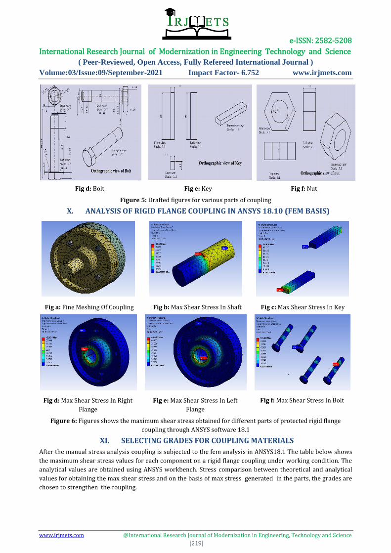
X. ANALYSIS OF RIGID FLANGE COUPLING IN ANSYS 18.10 (FEM BASIS)
Figure 6: Figures shows the maximum shear stress obtained for different parts of protected rigid flange
coupling through ANSYS software 18.1
XI. SELECTING GRADES FOR COUPLING MATERIALS
After the manual stress analysis coupling is subjected to the fem analysis in ANSYS18.1 The table below shows
the maximum shear stress values for each component on a rigid flange coupling under working condition. The
analytical values are obtained using ANSYS workbench. Stress comparison between theoretical and analytical
values for obtaining the max shear stress and on the basis of max stress generated in the parts, the grades are
chosen to strengthen the coupling.
Fig a: Fine Meshing Of Coupling Fig b: Max Shear Stress In Shaft Fig c: Max Shear Stress In Key
Fig d: Max Shear Stress In Right
Flange
Fig e: Max Shear Stress In Left
Flange
Fig f: Max Shear Stress In Bolt

e-ISSN: 2582-5208 International Research Journal of Modernization in Engineering Technology and Science
( Peer-Reviewed, Open Access, Fully Refereed International Journal )
Volume:03/Issue:09/September-2021 Impact Factor- 6.752 www.irjmets.com
www.irjmets.com @International Research Journal of Modernization in Engineering, Technology and Science
[220]
Table 5. Selection of grades
parts
materials
Selection
of grades
Permissible shear
stresses FOS=2.5
Theoretical
solution(in
N/mm²)
Analytical
solution
(N/mm²)
Max shear stress
generated in parts
shaft Carbon
steel
C60 (412/2.5)*.5=82.5 60.8 82 82
flange Grey cast
iron
Fg260 (260/2.5)*.5=52 7.73 45.489 45.5
bolt Carbon
steel
C60 (412/2.5)*.5=82.5 38.65 91.468 91.5
key Carbon
steel
C60 (412/2.5)*.5=82.5 53.96 76.699 77
Table 6. Selected grades
Parts Materials Grades
Shaft Carbon Steel C60
Key Carbon Steel C60
Bolt Carbon Steel C60
Flange Grey Cast Iron FG260
XII. BOUNDARY CONDITIONS
This structural analysis is performed to find out the suitable design for given flange coupling model. Present
coupling model is designed to transmit the power of 37.5 KW at 180 rpm. Following are the boundary condition
used for this analysis-
Table 7.Boundary conditions
Moment applied 2984155 N-mm
Support One end is fixed
Nodes 42295
Elements 22565
XIII. RESULTS AND CONCLUSION
The table below shows the maximum shear stress values for each component on a rigid flange coupling under
working condition. The analytical values are obtained using ANSYS Workbench
Table 8. Max stresses generated in parts.
Materials for different
parts of coupling
Theoretical solution (in
N/mm²) (manually
calculated values)
Analytical solution
(N/mm²)(computationally
calculated values)
Maximum stress
generated in parts
Carbon steel (ductile
material) for shaft c60
60.8 82 82
Grey cast iron (brittle
material) for flange fg200
7.73 45.489 45.5
Carbon steel (ductile
material for bolt c60
38.65 91.468 91.5

e-ISSN: 2582-5208 International Research Journal of Modernization in Engineering Technology and Science
( Peer-Reviewed, Open Access, Fully Refereed International Journal )
Volume:03/Issue:09/September-2021 Impact Factor- 6.752 www.irjmets.com
www.irjmets.com @International Research Journal of Modernization in Engineering, Technology and Science
[221]
Carbon steel (ductile
material for key c60
53.96 76.699 77
Results obtained from the ANSYS software are compared with theoretical solution of the task. From the above
table it is seen that various stresses induced in different parts of the flange coupling are more than the
theoretical value. Therefore, in this work, design of flange coupling is safe for the given torque and the required
power output if c60 for ductile and fg260 for brittle are chosen. The optimized grade for each component has
been selected.
XIV. REFERENCES
[1] Coupling Wikipedia, https://en.wikipedia.org/wiki/Coupling
[2] V.B. Bhandari, Machine Design Data Book, ISBN: 93-5134-284-0 (978-93-5134-284-7) Chapter 9.6
Coupling
[3] Prof. R.S.Powar,Prof. N.S Deshmukh, Dr. S.D.Suryawanshi, Flexible Coupling a New Approach , IOSR
Journal of Mechanical and Civil Engineering (IOSR-JMCE) ISSN: 2278-1684, PP: 01-
06www.iosrjournals.org
[4] Rajgadia, S., Das, D., Jaiswal, P., Basnet, A., Jha, A.R., Jaiswal, R., Karki, A. And Barman, R.N., Design and
Stress-Analysis of a Rigid Flange Coupling using FEM. Vol.4, Issue 10, October 2015ISSN(Online) :2319-
8753 ISSN (Print) : 2347-6710International Journal of Innovative Research in Science, Engineering and
Technology(An ISO 3297: 2007 Certified Organization)
[5] KB, G. And Chittappa, H.C., 2014. INTERNATIONAL JOURNAL OF ENGINEERING SCIENCES &
RESEARCH TECHNOLOGY Wear Performance and Hardness Property Of A356. 1 Aluminium Alloy
Reinforced with Zirconium Oxide Nano Particle. ISSN: 2277-9655 Impact Factor: 4.116 CODEN: IJESS7
Sonwane* et al., 6(8): August, 2017] IC™ Value: 3.00
[6] Sonwane, P.K. and Yadav, P., INTERNATIONAL JOURNAL OF ENGINEERING SCIENCES & RESEARCH
TECHNOLOGY STRUCTURAL ANALYSIS OF RIGID FLANGE COUPLING BY FINITE ELEMENT METHOD.
ISSN: 2277-9655 Impact Factor: 4.116 CODEN: IJESS7 Sonwane* et al., 6(8): August, 2017] IC™ Value:
3.00
[7] Shaikh, A.A.S., Taji, S. And Verma, A., 2018. Analytical Analysis of Relationship among Modal
Parameters of Rigid Flange Coupling. Asian Journal For Convergence In Technology (AJCT), 4(3).
[8] Singh, S. And Bhushan, B., 2017. Finite Element Analysis and Weight Reduction of Flange coupling using
CAE tools. [Vol. 03, Issue 4, May -2017 International Journal of Advances in Scientific Research.
[9] Formulas for calculations are taken from Design of Machine Elements ,VB Bhandari
[10] from “design data handbook” by K Mahadevan and K Balaveera Reddy(pg. no 251)
[11] Vijaya, V.G., 2013. Analysis of Rigid Flange Couplings. International Journal of Innovative Research in
Science, Engineering and Technology, 2(12). ISSN: 2319-8753 International Journal of Innovative
Research in Science, Engineering and Technology (An ISO 3297: 2007 Certified Organization) Vol. 2,
Issue 12, December 2013.