design, analysis and simulation of a novel device for ... · da perna, é substituída por um...
TRANSCRIPT

Design, Analysis and Simulation of a Novel Device for
Locomotion Support
Rita Gonçalves Cardoso
Thesis to obtain the Master of Science Degree in
Biomedical Engineering
Supervisors: Prof. Miguel Pedro Travares da Silva
Dr. Manuel Cassiano Neves
Examination Committee
Chairperson: Prof. Raul Daniel Lavado Carneiro Martins
Supervisor: Prof. Miguel Pedro Travares da Silva
Members of the Committee: Prof. Marco Alexandre de Oliveira Leite
Prof. João Eurico Cabral da Fonseca
November 2015

i
Agradecimentos
Quero agradecer ao meu orientador, o Professor Miguel Tavares da Silva, pelo papel fundamental que
teve no desenvolvimento deste trabalho, começando pela discussão de ideias, pelas sugestões e pelo
apoio que foi dando ao longo destes meses.
Ao Dr. Cassiano Neves, o meu obrigado por me ter ajudado a compreender o potencial do meu trabalho
e me ter mostrado as aplicações práticas do mesmo.
Quero também agradecer ao Professor Luís Sousa pela sua disponibilidade e pela sua ajuda nas
dúvidas de Soliworks que foram surgindo ao longo do trabalho.
Um agradecimento especial ao Grupo de Biomecânica, pelo brain storming constante; em particular ao
Sérgio Gonçalves, por todo o apoio, discussão de ideias e paciência com que me ajudou e ao João
Amorim Marques, pelo trabalho que teve com a impressão 3D e por todas as sugestões e conversas
que ajudaram a completar o meu trabalho.
Aos meus amigos, um agradecimento muito especial por me terem apoiado e ajudado durantes estes
meses e por termos partilhado as alegrias e amarguras da vida de estudante. Felizmente, a lista é
grande demais para vos enumerar a todos, mas gostava de referir o apoio essencial da Mariana Costa,
Joana Chim, Ricardo Ferreira e Carlos Carreira durante estes últimos meses. À Inês Mendes e ao
Rodrigo Almeida, um grande obrigado pela paciência e ajuda que me deram. Quero agradecer também
ao Bernardo Fazenda, por me ter mostrado sempre o lado positivo das coisas.
Quero agradecer à minha família, em especial aos meus pais por me terem motivado nas alturas difíceis
e por terem vivido cada vitória como se fosse deles. Obrigada por todo o apoio incondicional e por
terem sempre acreditado em mim.
A todos o meu sincero obrigado.
Ao meu avô, António da Silva Cardoso, dedico o meu esforço e dedicação, como agradecimento por
tudo o que me ensinou.
ii
Resumo
O envelhecimento da população, aliado à elevada incidência de doenças cardiovasculares,
neurológicas e musculosqueléticas, aumentou o número de pessoas com patologias da marcha. As
soluções disponíveis para este problema são ortóteses tornozelo-pé (AFO) passivas, apresentando
limitações visto não haver fornecimento de energia, como acontece com as AFO activas, restringindo
apenas o movimento do pé.
O objectivo deste trabalho é desenvolver um novo conceito de AFO com dualidade passiva/activa. A
solução convencional, composta por dois módulos (superior e inferior) ligados por juntas na zona lateral
da perna, é substituída por um mecanismo de quatro barras modificado com um sistema de duas
calhas. O dispositivo tem duas particularidades, é uma solução modular pronta-a-usar, facilmente
ajustável a qualquer doente, e tem um mecanismo exterior adaptável a diferentes problemas de
marcha.
Desenvolveu-se, in silico, um modelo CAD da ortótese que segue as normas de projecto mecânico para
a escolha das tolerâncias de ajustamento e dos elementos de máquina necessários à sua montagem.
Fez-se a simulação do movimento para validação do modelo e para garantir o constrangimento do
sistema com um grau de liberdade (flexão plantar e dorsiflexão) e a preservação do eixo de rotação
biológico do pé.
Os resultados da simulação permitiram a caracterização de uma passada não-patológica. O controlo
do dispositivo é feito por um actuador ou por elementos mecânicos como molas ou elásticos. São
apresentadas as relações entre o movimento das barras e o binário do motor/momento do tornozelo,
permitindo a caracterização das necessidades do actuador (velocidade, potência e torque).
Palavras-chave: Ortótese Pé-Tornozelo, Solução Modular, Dispositivo Biomédico, Pé Pendente

iii
Abstract
The number of people with drop foot gait is rising due to the increasing number of cardiac diseases,
demographic ageing and neurological and musculoskeletal disorders. Current solutions for this problem
are passive ankle-foot orthoses (AFO) that present limitations as they do not add energy to the system,
like active devices, restraining only foot motion.
This work aims the development of a novel AFO concept with passive/active duality. The conventional
configuration, composed by a superior and inferior modules, connected through two lateral joints, is
replaced by a new mechanism based on a modified four bar linkage with a two-rail system. The device
has two particular features, a modular solution “off-the-shelf”, easy to adjust to any patient, and an
exterior mechanism able to assist different gait impairments.
An in silico CAD model of the orthosis is developed following mechanical design standards to establish
dimensional and geometrical tolerances and the machine elements to assemble the device. Motion
simulation is performed to validate the model and ensure that the device constrains the foot to one
degree of freedom, which represents the dorsiflexion/plantar flexion, and the preservation of the
biological foot axis.
Results of the simulation allow the successful characterization of one stride and its correlation with
normal gait pattern. The device can be controlled by an actuator or simple mechanical elements, such
as elastic bands and springs. Relations between bars motions and motor torque/ankle moment are
presented, enabling the characterization of actuator’s torque needs (velocity, power and engine torque).
Key words: Ankle-Foot Orthosis (AFO), Modular Solution, Biomedical Device, Drop Foot
iv
Contents
Agradecimentos ..................................................................................................................................... i
Resumo................................................................................................................................................... ii
Abstract ................................................................................................................................................. iii
List of Tables ....................................................................................................................................... vii
List of Figures ..................................................................................................................................... viii
List of Acronyms ................................................................................................................................... x
List of Symbols ..................................................................................................................................... xi
Chapter 1
Introduction ............................................................................................................................................ 1
1.1 Motivation ................................................................................................................................ 1
1.2 Literature Review ..................................................................................................................... 2
1.3 Objectives ................................................................................................................................ 4
1.4 Main Contributes ..................................................................................................................... 5
1.5 Structure and Organization ...................................................................................................... 5
Chapter 2
Gait Cycle ............................................................................................................................................... 7
2.1 Ankle-Foot Complex: basic concepts ...................................................................................... 7
2.2 Gait Cycle .............................................................................................................................. 10
2.3 Gait Pathologies .................................................................................................................... 12
2.3.1 Drop foot Gait .................................................................................................................... 12
2.4 Common Pathologies Affecting Gait ..................................................................................... 13
2.4.1 Parkinsonism ..................................................................................................................... 13
2.4.2 Cerebral Palsy ................................................................................................................... 14
2.4.3 Myelomeningocele ............................................................................................................. 14
Chapter 3
Technical Aids for Locomotion .......................................................................................................... 15
3.1 Orthoses ................................................................................................................................ 15
3.1.1 Class of devices................................................................................................................. 16
3.2 Types ..................................................................................................................................... 16
3.2.1 Non-Articulated .................................................................................................................. 16
3.2.1 Articulated .......................................................................................................................... 17
3.3 Actuation ................................................................................................................................ 17
3.3.1 Passive Dynamic Orthoses ............................................................................................... 18
3.3.2 Semi-Active Orthoses ........................................................................................................ 19
3.3.3 Active Orthoses ................................................................................................................. 19

v
3.4 Market Options ...................................................................................................................... 21
Chapter 4
Concept Development: from an idea to a in silico working model ................................................ 23
4.1 Initial Idea .............................................................................................................................. 23
4.1.1 Novelty of the Concept and Preliminary Description of the System .................................. 24
4.2 Synthesis of the Mechanism .................................................................................................. 27
4.2.1 Four Phase Process .......................................................................................................... 27
4.2.1.1 Phase 1 ...................................................................................................................... 27
4.2.1.2 Phase 2 ...................................................................................................................... 27
4.2.1.3 Phase 3 ...................................................................................................................... 28
4.2.1.4 Phase 4 ...................................................................................................................... 29
4.2.2 Design Specifications ........................................................................................................ 30
4.2.2.1 Basic Principles ......................................................................................................... 30
4.2.2.2 Four-Bar Linkage Mechanism ................................................................................... 31
4.2.2.3 Range of Motion ........................................................................................................ 33
4.2.2.4 Uncanny valley .......................................................................................................... 34
4.3 Actuation Unit ........................................................................................................................ 35
4.3.1 Duality: Articulated and Non-Articulated ............................................................................ 35
4.3.1.1 Non-Articulated AFO ................................................................................................. 36
4.3.1.2 Articulated AFO ......................................................................................................... 36
4.3.2 Duality: Active and Passive ............................................................................................... 36
4.3.2.1 Passive Orthosis ........................................................................................................ 37
4.3.2.2 Active Orthosis ........................................................................................................... 41
4.4 Orthosis ................................................................................................................................. 43
4.4.1 Cover ................................................................................................................................. 43
4.4.2 Connection Elements ........................................................................................................ 44
Chapter 5
Mechanical and Technical Design Considerations .......................................................................... 47
5.1 Mechanism ............................................................................................................................ 47
5.1.1 Bars ................................................................................................................................... 47
5.1.2 Support Unit ....................................................................................................................... 49
5.2 Actuator ................................................................................................................................. 50
5.3 In Silico Assembly of the Orthosis ......................................................................................... 51
5.4 Mechanical Design ................................................................................................................ 52
5.4.1 Machine Elements ............................................................................................................. 52
5.4.1 Dimensional and geometrical tolerances .......................................................................... 53
5.5 Motion Analysis ..................................................................................................................... 55

vi
5.5.1 Simulation .......................................................................................................................... 55
5.5.2 Relation between distance and angle ............................................................................... 56
5.5.3 Relation between bar angles ............................................................................................. 57
5.5.4 Relation between moment and bar angulation .................................................................. 59
5.6 Torque needs......................................................................................................................... 62
5.6.1 Moment .............................................................................................................................. 62
5.6.2 Velocity .............................................................................................................................. 63
5.6.3 Power ................................................................................................................................. 65
5.6.4 Engine Torque ................................................................................................................... 65
5.7 Rapid Prototyping of the Designed Orthotic Device .............................................................. 66
Chapter 6
Conclusions and Future Work ........................................................................................................... 69
6.1 Conclusions ........................................................................................................................... 69
6.2 Future Work ........................................................................................................................... 71
References ........................................................................................................................................... 73
Appendix A: Drawings ........................................................................................................................ A1
vii
List of Tables
Table 4.1: Passive actuation components and respective response .................................................... 39 Table 5.1: Dimensions of the bars ......................................................................................................... 48 Table 5.2: Machine Elements and their properties ................................................................................ 53 Table 5.3: Table of the Tolerances chosen ........................................................................................... 55

viii
List of Figures
Figure 2.1: Anatomical Reference Position and Anatomical Planes, adapted from (Whittle, 2007),
ankle-foot motion on the sagittal plane, adapted from (Palastanga & Soames, 2012) ........................... 8 Figure 2.2: The bones and joints of the lower limb, adapted from (Palastanga & Soames, 2012) ......... 9 Figure 2.3: Axis deviation of the foot joint. Adapted from (Palastanga & Soames, 2012) ................... 10 Figure 2.4: Graphic Summary of Gait Cycle – L: left; R: right; HS: heel strike; FFL: full forefoot land;
HL: heel lift; TO: toe off. Adapted from (Michaud, 2011) ....................................................................... 10 Figure 2.5: Normal range of ankle motion during one stride. Adapted from (Winter, 1990) ................. 11 Figure 2.6: Representation of some abnormal gait patterns A – Steppage gait, B – Cicumduction, C –
Vaulting. Adapted from (Whittle, 2007) ................................................................................................. 13 Figure 3.1: Non-Articulated AFO: examples. Adapted from (ÖSSUR, 2015), (Fillauer, 2015) and
(Trulife, 2015) ........................................................................................................................................ 17 Figure 3.2: Articulated AFO: examples. Adapted from (ArizonaAFO, 2015), (Ottobock, 2015),
(OrthoBaltic, 2015) and (c-prodirect, 2015) ........................................................................................... 17
Figure 3.3: A – Solid polypropylene AFO, adapted from (Vistamehr et al., 2014), B – Carbon Fibre
AFO design, C – SLS manufactured AFO prototypes, adapted from (Faustini et al., 2008) ................ 18 Figure 3.4: A – Osaka Magneto Rheology (MR) damper AFO, adapted from (Kenneth Alex Shorter et
al., 2013); B –AFO with Jack Spring, adapted from (Ward et al., 2011) ............................................... 19
Figure 3.5: A - Powered AFO with Pneumatic Muscles, adapted from (Gordon et al., 2006), B -
Portable-Powered AFO, adapted from (K Alex Shorter et al., 2011), C - MIT active AFO, adapted from
(Herr, 2009), D – DACHOR, adapted from (Melo et al., 2011) ............................................................. 21 Figure 4.1: A – Conventional Passive AFO, B – Conventional Active AFO, C – AFO new model ....... 24 Figure 4.2: Identification of bars and key points .................................................................................... 25
Figure 4.3: Rails’ location and labelling ................................................................................................. 26 Figure 4.4: Displacement (mm) of point b (Z, X) and point f (Z, X) ....................................................... 28
Figure 4.5: Comparison of rails’ shape and their mathematical correlation .......................................... 29
Figure 4.6: Rails’ shape determination process. ................................................................................... 30
Figure 4.7: Four bar linkage mechanism, adapted from (Freudenstein, 1955) ..................................... 32 Figure 4.8: Orthosis model and limits of motion: A – neutral (0º); B – Dorsiflexed (15º); C – Plantar
flexed (15º) ............................................................................................................................................ 34 Figure 4.9: The Uncanny Valley, adapted from (Mori, 1970) ................................................................ 34
Figure 4.10: Support unit (left) and connection bars (right) ................................................................... 35 Figure 4.11: A - Non-articulated AFO, B and C - detailed view of the bands ........................................ 36 Figure 4.12: A – Connection bar of the active solution; B – Connection bar of the passive solution.... 37
Figure 4.13: A – Spring key features; B – Jack Spring™Actuator, adapted from (Hollander et al., 2005)
............................................................................................................................................................... 42
Figure 4.14: A – Passive Solution; B – Active Solution ......................................................................... 44 Figure 4.15: Left: Bar D with inferior connection and the inferior connection; Right: superior connection
............................................................................................................................................................... 45 Figure 5.1: Bars and support unit; highlight of the curved corners and numbering of the support’s
features: A – bar A; B – bar B; C – bar C; E – bar E; 1 – link sites of the connection elements; 2 –
bearing brackets for bar E; 3 – slot for the superior connection; 4 – Rail 1; 5 – internal edge; 6 – pin of
point f. .................................................................................................................................................... 50
Figure 5.2: Actuator: Screw (S), Thread (T), Ball Bearing (BB), Motor (M) and Box (B) ...................... 51 Figure 5.3: Frames of the simulation, from dorsiflexion (first) to plantar flexion (last), t (sec) .............. 56 Figure 5.4: Linear Displacement of magnitude (X and Z) in relation to the angle of bar D with Z axis
(red dots); linear regression (black line) ................................................................................................ 57 Figure 5.5: Up: Euler angles of Bar E (top) and Bar D (bottom); Down: relation between the angles .. 58
ix
Figure 5.6: Range of Motion during stride: Ankle (dashed red line) and Bar E (blue line) .................... 59 Figure 5.7: A: moment arm; B: point of application and direction of the force for neutral position,
plantar flexion and dorsiflexion .............................................................................................................. 60 Figure 5.8: Relation between motor torque and rotation angle of bar D for a unitary moment ............. 61
Figure 5.9: Moment per body mass during gait: mean value of ankle moment (red dashed line)
adapted from (Winter, 1991); bar E moment (blue line) ........................................................................ 62 Figure 5.10: Moment of force: ankle (red dashed line) adapted from (Winter, 1991); and bar E (blue) 63 Figure 5.11: Angular velocity: ankle (red dashed line) adapted from (Winter, 1991); and bar E (blue
line) ........................................................................................................................................................ 64
Figure 5.12: Power per body mass: bar E ............................................................................................. 65 Figure 5.13: Engine Torque ................................................................................................................... 66 Figure 5.14: 3D printing – parts of the orthosis ..................................................................................... 68 Figure 5.15: Functional Prototype – Assembly of the orthosis .............................................................. 68

x
List of Acronyms
AFO: Ankle-Foot Orthoses
CAD: Computer Aided Design
DOF: Degrees of Freedom
ES: Early Swing
FES: Functional Electrical Stimulation
FF: Foot Flat
FC: Foot Clearance
HC: Heel Contact
HO: Heel Off
HS: Heel Strike
IC: Initial Contact
LS: Late Swing
MR: Magnetorheolgic
MS: Mid Stance
PD-AFO: Passive Dynamic devices
PO: Push Off
ROM: Range of Motion
SEA: Series Elastic Actuator
SLS: Selective Laser Sintering
STL: Standard Tessellation Language
WA: Weight Acceptance
xi
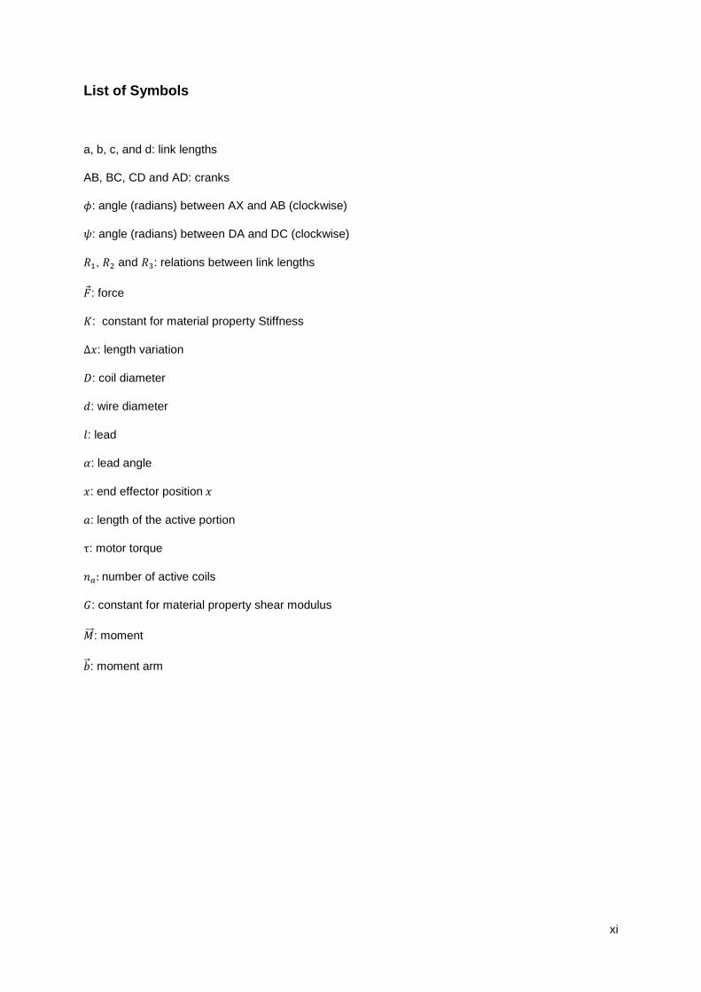
List of Symbols
a, b, c, and d: link lengths
AB, BC, CD and AD: cranks
𝜙: angle (radians) between AX and AB (clockwise)
𝜓: angle (radians) between DA and DC (clockwise)
𝑅1, 𝑅2 and 𝑅3: relations between link lengths
�⃗�: force
𝐾: constant for material property Stiffness
∆𝑥: length variation
𝐷: coil diameter
𝑑: wire diameter
𝑙: lead
𝛼: lead angle
𝑥: end effector position 𝑥
𝑎: length of the active portion
τ: motor torque
𝑛𝑎: number of active coils
𝐺: constant for material property shear modulus
�⃗⃗⃗�: moment
�⃗⃗�: moment arm

1
Chapter 1
Introduction
1.1 Motivation
Nowadays the medical community is becoming more and more aware of the importance of improving
the quality of life in patient healthcare. In a world where people can easily live until their 80’s or 90’s, the
big question is if they have the necessary support to enjoy and live those years to the fullest.
From the great variety of human movements, gait is so common that is usually described as trivial,
although it is one of the most complex and totally integrated movements. The ability of walk, from one
place to another, without depending on someone else to do it and with few or no limitations is a major
factor to peoples’ life quality. Walking is not only a tool for movement but also a key feature in social,
work and personal fulfilment.
There are two different aspects that have an effect on the capacity of performing normal gait: ageing
and pathologies, which englobe both gait pathologies, like drop foot gait resulting from stroke; and
conditions that affect gait, such as cerebral palsy. Portugal, just as other developed countries, is going
through a severe demographic ageing; according to information collected in the last Portuguese Censos
(2011), the number of elderly is increasing in comparison to the number of young people (“PORDATA:
Base de Dados Portugal Contemporâneo,” 2011). The number of cardiac diseases, such as stroke, is
also increasing and the number of cases per year is higher than 12.000; and according to the Censos
(2001) the number of people with cerebral palsy is around 15.000 (DGS, 2014). Among other effects,
these numbers can justify the fact that 25% of the population has difficulty in walking (INE, 2011).
Given the importance of walking there has always been interest in studying gait and in creating solutions
for correcting walking disabilities. Orthotics are one of the most common and widely used solutions. The
terminology of the word “orthotic” helps to understand its purpose: “ortho” means to “straighten or
correct” and the suffix “tic” refers to the “systematic pursuit of” (Prentice & Voight, 2001). There are
many different kinds of orthosis used as technical aid for walking based on their action: ankle, knee or
hip.
2
Ankle Foot Orthoses (AFO) are medical devices used to improve gait performance for persons with
lower limb disabilities, working as assistive or therapeutic devices (Faustini, Neptune, Crawford, &
Stanhope, 2008). They are broadly prescribed to correct gait pathologies but the available market
options only englobe passive solutions. When taking a closer look to the AFO’s market, is easy to
acknowledge the inexistence of active solutions which decrease the effectiveness and applicability of
these devices. Many active orthoses are being developed at academic level but they don’t make a leap
to the market because these solutions need to be adjusted for each patient.
There is the need to develop an active AFO that can be easily acquired and with the ability to be adjusted
to each wearer by the orthotist.
1.2 Literature Review
In Orthopaedics field, orthoses were the first device to arise and the first design is an knee stabilizer
from around 2730-2625 B.C. (Seymour, 2002). Between the mummies found in the Egyptian tombs
there were found intact orthoses made of leaves, canes, bamboo and tree bark used to stabilize bone
fractures (Alves da Silva, 2014). Greek civilization also left his mark in the orthoses history, Hippocrates
(460-377 B.C.) used splints to avoid pressure points in bony prominences and to reduce tibia fractures
(Rodrigues, 2012). It is during the Middle Age (year 1200) that Orthopaedics and orthoses are
recognized as a relevant feature in medical knowledge, by the medical school of Bologna. Only then the
choice of different materials started to be discussed with the purpose of reaching lighter and more
comfortable solutions (Rodrigues, 2012). In 1592, Hoerônimus Fabricius wrote the first book on orthoses
containing illustrations of orthotic devices whose design was based on armours, since the treatment of
musculoskeletal diseases was, back in those days, in charge of healers and blacksmiths (Alves da Silva,
2014).
In the XIX century with the arising number of work-related accidents and the consequences of civil wars,
there was a significant investment in orthopaedics, characterized by the changing from metal to wood
(Seymour, 2002). The XX century was marked by great developments in three sectors: materials, multi-
disciplinary and computer technology. There was the boom of new materials, plastic, carbon fibre and
titanium replaced the old materials allowing the production of lighter and more resistant devices (Alves
da Silva, 2014). Different schools, doctors, engineers and designers, started to work together to achieve
new and better products. In 1970 CAD (Computer Aided Design) software appears, revolutionizing the
way orthoses are design, correcting errors and improving their production (Rodrigues, 2012).
It’s in 1920 that the ancestor of articulated AFO arises, by Fred Tranmer that patented his invention
claiming that his device was composed of a lower member promoting arch support and an upper
member, connected by a pivot which protects the ankle joint (Tranmer, 1920).

3
The first reference to an active device is a US Patent from 1935 of a knee active support device (Cobb,
1935). In 1942 the first controllable active orthosis is found, with motion performed by hydraulic actuators
(hip-knee) (Filippi, 1942). Another patent from 1951 also describes a passive device with sprig-loaded
pins which locked and unlocked the joints of the brace at different stages of the gait cycle (hip-knee-
ankle) (Murphy, 1951). In 1981, University of Titograd developed an active AFO which consisted on a
DC motor that assisted flexion/extension of the ankle and was controlled by sensors localized on the
soles of the device (Dollar & Herr, 2008).
Technological evolution in this field is due to the development of several areas: robotics, biomechanics
and automation, and it is in the XXI century that this evolution starts to have a major role and impact in
orthoses history.
MIT Ankle-Foot-Orthosis was developed by the MIT Biomechatronics Group to assist drop foot gait. It
was a modified passive AFO equiped with a Series Elastic Actuators (SEA), pressure and rotary sensors
that allowed an impedance variation of flexion/extension movement of the ankle joint. This AFO prevents
foot slap and increases the walking speed of the wearer. The Human Neuromechanics Laboratory at
the University of Michigan (USA) developed several AFOs, all intended for rehabilitation environment
since they are not fully portable. Carbon fibre and polypropylene modules are custom-built for each
wearer and AFOs are mostly pneumatically actuated, through the use of artificial pneumatic muscles
(Blaya & Herr, 2004).
Active orthosis are difficult to wear in the daily life because they need a power source, so semi-active
devices play an important role on this matter. Osaka University developed magnetorheological dampers,
controlled by computer to facilitate the use of active devices. These dampers create a resistive torque
to plantar flexion during swing phase. Gait cycle is hence divided in four stages through the use of three
sensors that adjust the viscosity of the damper fluid for each stage (Alves da Silva, 2014). Arizona
University, also develop an AFO with an actuator called Robotic Tendon, that uses a spring system to
control ankle-foot motion (Hollander, Sugar, & Herring, 2005). Other semi-active AFO, such as BIONic
WalkAide and NESS L300, use functional electrical stimulation (FES) to support ankle flexion.
There are also passive AFOs which promote the control of plantar flexion and/or dorsiflexion through
mechanical elements such as springs. DACS (Dorsiflexion Assist Controlled by Spring AFO) was
developed in Japan, by the International University of Health, to prevent drop foot in hemiplegic patients
through a dorsiflexion control by spring elements (Alves da Silva, 2014). Illinois University, USA,
designed AFO to store energy during gait, the main goal is to support toe clearance in the end of stance
phase (Kenneth Alex Shorter, Xia, Hsiao-Wecksler, Durfee, & Kogler, 2013). Osaka University, in Japan,
create an AFO with passive pneumatic elements activated by the weight of the wearer. It is intend to
promote motion control and prevent foot droop during swing phase. The Rehabilitation Centre of
Kanagawa, Japan, build an AFO with an oil damper. This element resists plantarflexion and avoids foot
drop during swing phase (Alves da Silva, 2014).

4
1.3 Objectives
The objective of this work is to present a novel paradigm for the design of Ankle-Foot Orthosis by
changing the concept and structure that has been used since the first articulated AFO. This novel
concept uses an external joint mechanism to support the movement of the ankle joint. The proposed
solution can be applied both in passive and in active devices but it’s with an active configuration that the
major advantage is attained.
To achieve this goal the first step will be to use the software Solidworks® (Solidworks Student Edition
2015/2016 version 23.2.1.0001), to develop a CAD model of the device and simulate its effectiveness
and viability. Once this is achieved the next step is to make the mechanical engineering design of the
model and then build a functional 3D prototype using the CAD model and 3D printing.
The main ambition is to design a modular and compact device that can be adapt to any person, avoiding
the need of specific designs for every patient. The orthosis consist of three modules: two adaptable
parts, the upper and lower members, specific for each person and fabricated by the orthotist, and a
mechanical part, developed in this work, linking the other two parts and assisting the movement of the
ankle joint. This last module is chosen accordingly to the patient’s morphologic characteristics and
impairments: it can be an active or passive device, with different features for each case.
This new concept of AFO has three main features: availability, passive/active duality and functionality.
The three-module orthosis is intended to improve the production process of an AFO. This is
accomplished through the modular concept since the mechanism responsible for the motion is easily
acquired and fully constructed. This modular part can be send to anywhere in the world and, once there,
adjusted to the patient morphology and support needs. This way the fabrication process is simplified
considering that the complex part of the orthosis, i.e. the action mechanism, is already built. It is intended
to be a product “off-the-shelf” with several sizes, each one englobing a range of leg and foot lengths;
and with different features for each gait disorder and the degree of disability of each patient.
Another relevant feature is its multi-purpose design which allows changing from an active to a passive
device as well as choosing between an articulated or non-articulated orthosis, according to the wearer’s
requirements. Thereby the same orthosis can be chosen to different pathologies and different degrees
of disability by adapting the device to the best configuration with the appropriate connection elements.
The orthosis is designed to include an actuator if the patient needs an active device. It is also built to
work with mechanical elements such as springs and elastic bands with different stiffness to assist
various phases of the gait cycle.
One of the possible applications of this orthosis is rehabilitation. When patients need to recover from an
injury or to regain gait capacities, orthoses can be used to help the process. Since this AFO can be
adapted to many subjects it would be really useful for a rehabilitation environment, not only in the health
5
clinic but also at home. This leads to the other possible utilization of the device: this orthosis can be a
daily use wearable solution, to assist and improve the wearer’s gait.
1.4 Main Contributes
The main contributes of this thesis are:
- Development of a modular, compact orthosis adaptable to any wearer and different gait
pathologies;
- Design of a multifaceted orthosis with articulated or non-articulated features, and active or
passive actuation;
- Conceiving of an articulated “jointless” orthosis without a joint at the anatomical location, in
which a modified four bar linkage mechanism adapted with a novel two-rails system is proposed
that preserves the biological axis of ankle-foot rotation;
- Creation of a high efficiency device, which requires less motor torque to counteract ground
reaction forces and promote normal ankle movement;
- Motion analysis of the envisaged device and consequence study and analysis of the
requirements of a motor to equip an appropriate actuator.
1.5 Structure and Organization
This thesis is structured in six chapters:
Chapter 1: depicts the motivation and objectives of this work, as well as a literature review and main
contributes for this field of work.
Chapter 2: presents basic knowledge about the ankle-foot complex – anatomy and functional properties
–; gait cycle – phases and characteristics of normal gait –; and gait pathologies, with a special attention
being given to drop foot gait.
Chapter 3: gives an overview of the state of the art characterizing orthosis according to their type
(articulated and non-articulated) and actuation (passive, semi-active and active). The available options
in the market are also discussed.
Chapter 4: describes the evolution of the orthosis, from the initial sketch to the final concept. The
mechanism is fully detailed as well as the actuation unit and the final design. A special emphasis is
provided on the rails-bars conjunction, the main feature of the device.

6
Chapter 5: details the development of the orthosis’ CAD model in Solidworks® software where both
mechanism and actuator parts are described. Some technical specifications of the mechanical design
are explained such as the choosing of the right mechanical elements and the dimensional and
geometrical tolerances. The motion analysis performed is also displayed along with the results of the
simulation and their interpretation and discussion. The last part of the chapter is dedicated to the
construction of a functional 3D prototype, through 3D printing.
Chapter 6: presents the final considerations of the developed work, addressing the major conclusions
and some suggestions of future work on the subject such as developing a structure analysis, adapting
the design into a solution more compact and study the effects on gait cycle of wearing the AFO.
7
Chapter 2
2.
Gait Cycle
2.1 Ankle-Foot Complex: basic concepts
The interface between the human body and the ground is ensured by the ankle-foot complex. This
anatomical structure has an important role on weight baring, locomotion and maintaining a standing
upright posture so it’s important to understand how this structure is assembled from the anatomical and
functional perspectives to perform such complex tasks.
First it is necessary to understand some basic anatomical concepts and definitions.
The description of the position and movement of the limbs of the human body is usually made in relation
to the anatomical reference position. When in this position the body is standing upright on an orthostatic
position. The feet are slightly separated and the upper limbs are laterally suspended with the palm of
the hands facing forward (Whittle, 2007).
There are three reference planes that are used to characterize the movements of the limbs: sagittal,
frontal and transverse planes. Each plane divides the body in halve and allows a different type of motion.
Sagittal or anteroposterior plane: divides the body into right and left halves; the perpendicular
axis is the medio-lateral where the possible movements are flexion and extension. In the ankle
these movements are called dorsiflexion and plantar flexion and are represented in Figure 2.1.
Frontal or coronal plane: divides a body part into anterior and posterior portions; – the
movements of abduction and adduction take place in these plane on the antero-posterior axis.
In the ankle the respective movements take place on the midline of the foot and are called
eversion and inversion
Transverse plane: divides the body into upper/superior and lower/inferior portions, the possible
movements are internal and external rotation and take place along the longitudinal or vertical
axis (Whittle, 2007), (Hall, 2011).
The different planes and the anatomical reference position can be seen in Figure 2.1.

8
The ankle-foot joint is also capable of other movements such as pronation and supination that are a
combination of basic movements. Pronation occurs when eversion, dorsiflexion and abduction are
combined and supination includes inversion, plantar flexion and adduction (Whittle, 2007).
Figure 2.1: Anatomical Reference Position and Anatomical Planes, adapted from (Whittle, 2007), ankle-foot motion on the sagittal plane, adapted from (Palastanga & Soames, 2012)
The foot is a complex multibone structure which can be divided in three parts: the hindfoot, the midfoot
and the forefoot. It has 26 bones, with numerous joints between them: 7 tarsal bones that are divided
between the hindfoot and midfoot, 5 metatarsals and 14 phalanges which belong to the forefoot. A
schematic figure can be analysed in Figure 2.2.
The hindfoot or ‘rearfoot’ is the posterior part of the foot and consists of two bones – the calcaneus, and
the talus or astragulus –, which are the ankle and heel bones, respectively. The talus is the connection
between the foot and the leg, forming the ankle joint, the calcaneus articulates with the midfoot bones.
The midfoot consists of five bones, the navicular, the cuboid and three cuneiforme bones that articulate
with the metatarsals of the forefoot, the anterior part of the foot. There are 14 phalanges, also known as
the bones of the toes, three in each toe except on the big toe, where there are only two (Whittle, 2007),
(Palastanga & Soames, 2012).

9
Figure 2.2: The bones and joints of the lower limb, adapted from (Palastanga & Soames, 2012)
The ankle or ‘talocrural region’, is the connection between the leg and the foot, made through three
joints: the talocrural joint also known as the tibiotalar joint, the subtalar or talocalcaneal joint and the
inferior tibiofibular joint. The main bones of this region are the talus (foot bone), tibia and fibula (leg
bones). Most motion at the ankle occurs at the talocrural joint that is a synovial hinge joint with only one
degree of freedom allowing movement on the sagittal plane: dorsiflexion and plantar flexion (Palastanga
& Soames, 2012).
The range of motion (ROM) is the full movement potential of a joint. Joint motion varies with age, sex
and health status; its measurements are used to assess injuries and diseases in the locomotor system
(Roaas & Andersson, 1982). The neutral position of the foot is when the foot makes a right angle with
the leg, during stand position and the maximum range of motion is near 90°: with dorsiflexion having a
range of 30º and plantar flexion of 50º (Palastanga & Soames, 2012).
The talocrural joint connects the distal part of the tibia and fibula to the talus. It’s also responsible for
adjusting the line of gravity during standing and has a major role during gait. Three ligaments—the
anterior and posterior talofibular, and the calcaneofibular—reinforce the joint (Hall, 2011), (Palastanga
& Soames, 2012).
In the anatomical reference position, the axis of the talocrural joint is horizontal but with a deviation of
20° − 25° from the frontal plane (Palastanga & Soames, 2012). This means that it is slightly anterior to
the frontal plane when passes through the tibia but also slightly posterior to the frontal plane as it passes
through the fibula (Hertel, 2002). For most people the axis line starts 1 cm above the prominence on the
inner side of the ankle (lower end of the tibia) and ends 2 cm above the prominence on the outer side
of the ankle (lower end of the fibula) (Palastanga & Soames, 2012).

10
The shape of the bony elements and the support given by ligaments and tendons, give an arched form
to the foot. This characteristic is essential during gait, acting as a complex spring under tension, helping
reducing stress and minimizing the energy expenditure of walking (Palastanga & Soames, 2012).
During walking, each lower limb performs a sequence of movements that are repeated; the left and right
limbs work alternately with a phase shifting between them to provide support and propulsion, and this
process is called the gait cycle (Whittle, 2007).
2.2 Gait Cycle
Figure 2.4: Graphic Summary of Gait Cycle – L: left; R: right; HS: heel strike; FFL: full forefoot land; HL: heel lift; TO: toe off. Adapted from (Michaud, 2011)
The gait cycle, represented in Figure 2.4, can be defined as the sequence of the events between two
successive occurrences of one same event. It usually starts when a foot contacts the ground – Initial
Contact (IC) – and ends when that same foot makes a new IC (Whittle, 2007).
The duration of a complete cycle is known as stride period and can be divided in two phases: the stance
phase, which is the support or contact phase and takes about 60% of the cycle and the swing phase,
Axis of foot
Frontal Axis
Ankle joint axis
Figure 2.3: Axis deviation of the foot joint. Adapted from (Palastanga & Soames, 2012)

11
when the foot is moving forward through the air that lasts the other 40%. Each phase has different
periods; according to Winter the stance phase has three (Weight Acceptance (WA), Mid Stance (MS)
and Push Off (PO)) and the swing phase has two periods (Early Swing (ES) and Late Swing (LS))
(Winter, 1991), (Whittle, 2007).
At the time of IC, frequently called Heel Strike (HS) or Heel Contact (HC) the ankle is within a few
degrees from the neutral position. After that, the forefoot touches the ground through the action of the
ankle plantar flexores. The period of WA is characterized by a maximum knee flexion of the support
limb. During MS the foot is flat – Foot Flat (FF) – on the floor and the ankle joint becomes dorsiflexed.
The PO is the last period of stance when the lower limb is pushing away from the ground. It starts with
the heel leaving ground – Heel Off (HO) – and in this phase the ankle joint reaches the peak of
dorsiflexion before Toe Off (TO) when there is plantar flexion. The ankle progresses from dorsiflexion
to a plantar flexed posture through the controlled action of the tibialis anterior and the common toe
extensors and great toe extensor. This is the end of the stance phase and the beginning of the swing
phase. Until the end of TO there is a major plantar flexion of the foot.
Before the TO of one foot happens, the IC of the other foot occurs, this is called the loading response
and in this phase there is Double Support, which means that both feet are touching the ground at the
same time.
In the Swing Period the foot is airborne and not in contact with the ground. In this phase, the ankle goes
back to dorsiflexion until the forefoot is completely off the ground, called Foot Clearance (FC), and stays
in a neutral position until the next IC (Winter, 1991), (Whittle, 2007), (Dubin, 2014).
Between dorsiflexion and plantar flexion the average range of ankle motion during walking is 30° (20°
to 40°), usually the ROM is wider in plantar flexion than in dorsiflexion (Perry, 1992). The distribution of
ankle motion during the gait cycle is represented in Figure 2.5.
Figure 2.5: Normal range of ankle motion during one stride. Adapted from (Winter, 1990)

12
One of the main aspects of walking is its energy expenditure that is closely related to the location of the
body centre of mass. Several details of gait posture work together to reduce the deviations of the centre
of mass and keep the energy level approximately constant: these are called the gait determinants
(Saunders, Inman, & Eberhart, 1953). There are six gait determinants: pelvic rotation, pelvic tilt, knee
flexion in the stance phase, ankle and foot mechanism and lateral displacement of the body. Alterations
or loss of one or more of these determinants are related to pathological gait (Saunders et al., 1953).
2.3 Gait Pathologies
In order to keep the energy expenditure to its minimum, the normal values of gait determinants may
suffer some alterations in order to compensate for the lack of other gait determinant, causing a change
in the normal gait patterns. When two gait determinants are loss, effective compensation is impossible
and the energy cost of locomotion in highly increased (Saunders et al., 1953).
Some pathological gait patterns can be easily detected because of the abnormal movements that are
the result of the adaptation of people to pain and disorders in some part of the locomotor system such
as brain, spinal cord, nerves, muscles, joints and skeleton. In other cases, the changes in gait are not
compensating some flaw but are consequence of weakness, spasticity (excessive muscle contraction)
or deformity (Whittle, 2007).
Common comorbidities that may affect gait include neurologic, orthopaedic, cardiac and pulmonary
disorders (Dubin, 2014). Gait disorders can be categorized accordingly to its typical manifestations and
physical signs to help finding the associate pathology. There are four main categories: hemiparetic
(weakness on one side), paraparetic (bilateral weakness), spastic (alteration in muscle tonus) and
sensory (loss of sensory input, affecting the control of movement) (Jankovic, 2015). Gait deviations
involving the ankle-foot complex have a great influence in the gait cycle (Dubin, 2014).
2.3.1 Drop foot Gait
Drop foot is one of the most common gait dysfunctions, can result from neurogenic etiologies
(neuropathies), central nervous system disorders, cerebrovascular accident (stroke), multiple scleroses,
muscle disorders (myopathies) and mechanical dysfunction. It’s characterized by a weakness of the foot
dorsiflexors and/or plantar flexor muscles that leads to a longer limb (Dubin, 2014).
Impairment of the plantar flexor muscles affects the push-off phase. The major consequences are in the
energy cost of walking, which will increase because most of the power is no longer generated during
ankle push-off and on an alteration in the gait pattern, known as foot slap, where an uncontrolled slap
of the foot on the ground at heel strike occurs. (Alam, Choudhury, & Mamat, 2014).

13
Insufficient dorsiflexion leads to complications during midswing phase because the muscles are
incapable of lifting the foot causing an inadequate ground clearance, this affects the gait pattern since
there is dragging of the toe during swing (toe drag) (Alam et al., 2014).
To reduce the effects of drop foot, the body usually finds ways to adapt, such as steppage gait,
circumduction and vaulting; Figure 2.6 shows these gait patterns. These compensations try to
functionally shorten the long limb. In steppage gait, there is an excessive use of the hip and knee flexion
on the involved side. The foot is pending towards the ground and incapable of performing dorsiflexion.
In circumduction the swing phase limb is moved away from the midline of the body; in vaulting the patient
gets up on his toes during swing phase to clear the affected limb (Dubin, 2014).
Figure 2.6: Representation of some abnormal gait patterns A – Steppage gait, B – Cicumduction, C – Vaulting. Adapted from (Whittle, 2007)
AFO’s are usually design to assist the ankle-foot flexors and extensors during the gait cycle and are
commonly prescribed to improve drop foot gait.
2.4 Common Pathologies Affecting Gait
The neuromuscular system is responsible to adapt movement patterns to produce an efficient
ambulation. Pathologies that affect this system like Parkinsonism, Cerebral Palsy, Muscular Dystrophy
or Spinal Bifida will affect the gait pattern and lead to an abnormal locomotion (Fish, 1997).
2.4.1 Parkinsonism
Parkinson disease is caused by a degeneration of a brain area (basal ganglia, responsible for learning
and reproducing basic movement patterns) resulting in shuffling gait. In this condition the foot is still
B C A

14
moving forward at time of the IC so the first contact is made in some patients by foot flat, in others by
the heel but with the foot in an almost neutral position. This gait pattern usually evolves over the course
of several strides instead of stabilizing like in other gait patterns (Whittle, 2007).
The major alterations in gait pattern are a decrease in stride length as well as in the walking speed, and
the reduction of joint extension, affecting the range of motion at the hip, knee and ankle.
2.4.2 Cerebral Palsy
Cerebral palsy is a non-progressive injurie in the brain that can occur prenatally, perinatally or
postnatally and may affect one or more of the three brain areas involved in movement: basal ganglia –
responsible for learning and reproducing basic movement patterns –, motor cortex – chargeable for
stimulating muscles and groups of muscles to perform the movements – and cerebellum – where the
activity is monitored and feedback is given (Whittle, 2007).
Patients with cerebral palsy usually suffer from spasticity, asymmetric muscle involvement and have
their limbs oriented internally, affecting the base levers. These constraints have a major effect in the gait
pattern that is described as a “controlled fall” from one limb to another and is a result from spastic
hemiplegia. Other characteristics of the gait pattern are the loss of selective muscle control and deficient
equilibrium reactions. These alterations cause a major increase of the metabolic cost of walking (Whittle,
2007), (Fish, 1997).
2.4.3 Myelomeningocele
Commonly known as ‘spina bifida’ results from the abnormal development of the lower part of the spinal
cord (Whittle, 2007). General gait characteristics are limb hypotonicity (low muscle tonus) and flexed
posturing of the lower limbs. There is a decrease in gait velocity to reduce energy loss.

15
Chapter 3
3.
Technical Aids for Locomotion
To respond to the needs of those who have gait impairments, there are many solutions available such
as canes, crutches, wheel chairs, orthoses and many others. This chapter is focused on orthoses,
particularly in Ankle Foot Orthoses (AFO). Here we will analyse their specificities and applications, as
well as browse through different kinds of AFOs.
3.1 Orthoses
The first patents for medical inventions related to locomotion support, such as ankle-foot orthoses,
remote to the early XX century (Stevens, 1906). Ortho-prosthetic development was impelled and
stimulated by consequences of the First World War and polio epidemic. Looking back to the initial
proposed solutions, it can be observed that the basic idea and functionality of lower limb orthoses hasn’t
changed significantly for more than 100 years. New technologies and materials replaced the early
solutions but the basic concept is still the same.
Orthoses can be defined as anthropomorphic mechanical devices that are used by an operator and
work according with his/her movements; these devices are usually intended to assist people with gait
pathologies (Herr, 2009).
There are many different designs of orthoses, with different applications. Their design specifications
may refer to mechanics (joints, degrees of freedom, range of motion, kinematic alignment), actuation
and control (torque, speed and bandwidth), weight distribution (inertia) and physical interface with the
user (Cenciarini & Dollar, 2011).
One of the most common gait dysfunctions, known as drop foot gait, affect a large number of people
around the world and AFOs are commonly prescribed to assist them (Herr, 2009). AFO design to prevent
this gait impairment must be able to provide moderate resistance during loading response (inhibit foot-
slap), allow free dorsiflexion in stance phase and provide large resistance during swing phase to hinder

16
foot drop (Alam et al., 2014). Gait can be improved by a mechanical compensation of the plantar flexor
and dorsiflexor muscles weakness (Harper, Esposito, Wilken, & Neptune, 2014).
3.1.1 Class of devices
Medical devices are divided into four risk categories, accordingly to the vulnerability of the human body
(duration of the period of contact with the device, invasiveness of the procedure and localization of the
device) and the potential risks of the technic and fabrication of the device (Infarmed, 2009).
According to this classification orthoses belong to Class I (low risk device) and are considered custom-
made medical devices. Their registry follow the Article 11 of Decree-Law 145/2009, of 17 July (Infarmed,
2009).
3.2 Types
The structure of an AFO can be non-articulated (or “hingeless”), which are devices composed of a rigid
structure with low or very low flexibility, or articulated (or “hinge”), which are orthoses that have a revolute
joint (hinge) placed near the talocrural joint (Milusheva, Tosheva, Tochev, & Toshev, 2007).
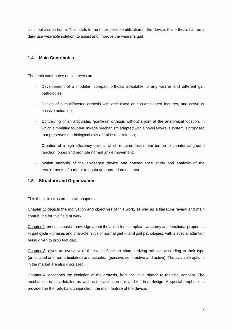
3.2.1 Non-Articulated
Non-articulated AFO’s are usually composed by only one component that connects the base of the foot
to the leg. This type of AFO tends to be static although there are some which are composed of two units
connected by mechanical elements like springs, while still having a fixed joint.
The use of static AFO’s improves standing, balance and the walking performance of chronick stroke
patients by increasing the loading under the paretic limb and reducing the sway of the center of pressure
(Chern, Chang, Lung, Wu, & Tang, 2013).
Ankle plantar flexors play an important role on generating forward propulsion in gait and in dynamic
balance control. The use of static AFO’s limits the range of motion of these ankle muscles and foot,
hindering the normal gait pattern and the walking capacity of the wearer.
Some design exemples of this type of AFO can be seen in Figure 3.1.
17
Figure 3.1: Non-Articulated AFO: examples. Adapted from (ÖSSUR, 2015), (Fillauer, 2015) and (Trulife, 2015)
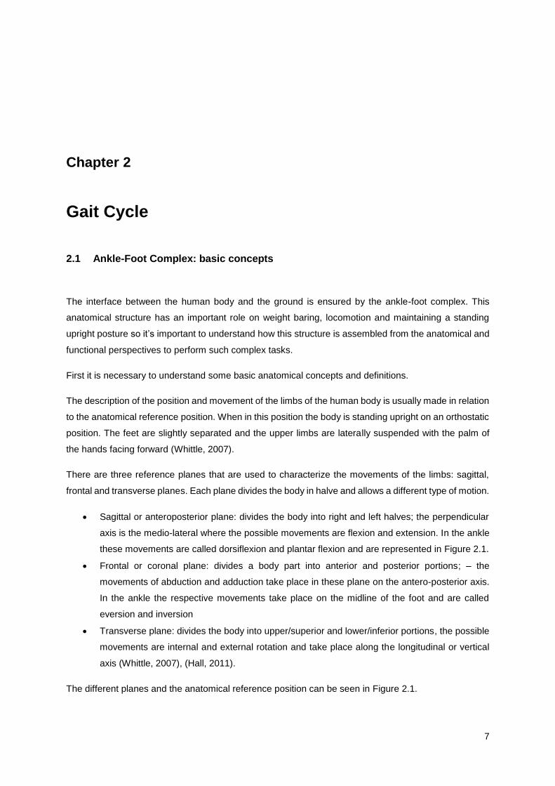
3.2.1 Articulated
Articulated AFO are usually composed of two modules: the upper module that is attached to the leg and
the lower module that supports the foot. As the name implies, the connection between these modules
is made through a joint that allows foot dorsiflexion and plantar flexion. Some examples can be seen in
Figure 3.2.
Figure 3.2: Articulated AFO: examples. Adapted from (ArizonaAFO, 2015), (Ottobock, 2015), (OrthoBaltic, 2015) and (c-prodirect, 2015)
The motion control elements most regularly used in these devices are springs, passive pneumatic
elements, one way friction clutches and oil dampers, in the case of passive solutions and series elastic
actuator (SEA), magnetorheological fluids, artificial pneumatic muscle and shape memory alloys for
active or semi-active solutions (Alam et al., 2014).
Each AFO is usually built accordingly to the patients’ needs, so different designs will have different
ranges and degrees of motion but in common all have the same purpose which is to improve gait.
3.3 Actuation
Considering the type of actuation some authors like Hugh Herr, (Herr, 2009), divide AFOs in two groups:
Passive and Active Orthoses, while other such as Shorter and colleagues (Kenneth Alex Shorter et al.,
18
2013) and Alam and colleagues (Alam et al., 2014), add another group called Semi-Active Orthoses,
which is a sub-group of Active Orthoses. In this work the terminology fallowed is the later one.
The great difference between Passive devices and Semi-Active/Active devices is that the first group
contain no control or electronic elements, the distinctive mark of Semi-Active/Active Orthoses. Active
AFO are able to provide energy to the ankle, while Passive and Semi-Active can only dissipate, store
and release available energy (Kenneth Alex Shorter et al., 2013), (Alam et al., 2014).
3.3.1 Passive Dynamic Orthoses
Passive Dynamic devices (PD-AFO) rely on material properties, orthosis design, springs and fluid
pressure dynamics to restrict bending and rotational stiffness as well as to accumulate and release
mechanical energy (Faustini et al., 2008), (Schrank & Stanhope, 2011).
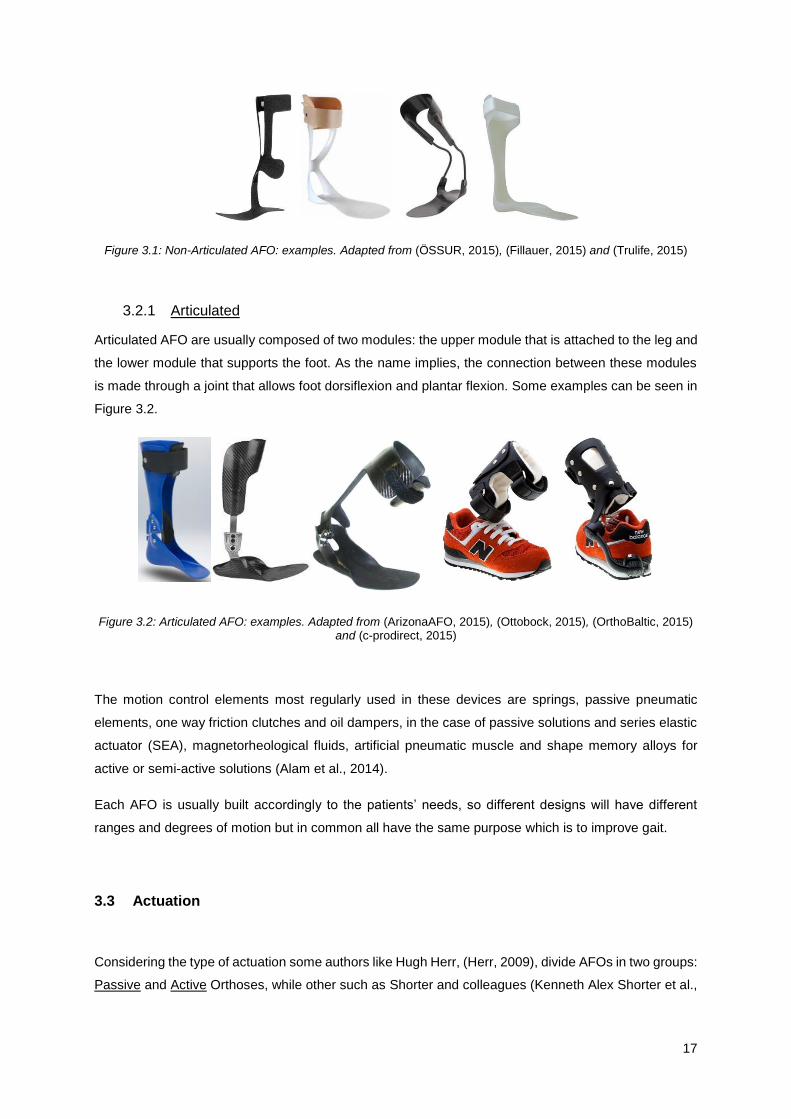
The most commonly used AFOs in rehabilitation are made of polypropylene or carbon fibre and have
an L-shape design (as seen in Figure 3.3: A and B). Wearing this kind of AFO affects the generation of
propulsive impulses, dynamic balance and regulation of whole body angular momentum in frontal and
sagittal planes. Their prescription often requires careful thought so as not to hinder the wearer
(Vistamehr, Kautz, & Neptune, 2014).
Since this type of AFOs is the most commonly prescribed and its fabrication process is very labour
intensive to match the unique gait dynamics of each patient, some studies have been made exploring
new manufacturing technologies. The most promising one is Selective Laser Sintering (SLS) (Harper et
al., 2014), (Faustini et al., 2008), (Schrank & Stanhope, 2011).
This technology uses digital data about the patient limb morphology to create a computer aided design
(CAD) model of the AFO allowing its detailed structural analysis. This way the orthotic device has a
higher compatibility with the wearer and can be designed accordingly with the patient needs (Faustini
et al., 2008), (Schrank & Stanhope, 2011). In Figure 3.3: C it’s possible to see an example of an AFO
fabricated through SLS from a CAD model.
Figure 3.3: A – Solid polypropylene AFO, adapted from (Vistamehr et al., 2014), B – Carbon Fibre AFO design, C – SLS manufactured AFO prototypes, adapted from (Faustini et al., 2008)
A B C
19
3.3.2 Semi-Active Orthoses
Semi-active or sometimes also referred to as pseudo-active orthoses are a sub group of active orthoses
that has the particularity of not presenting a source of power in the design solution. The active elements
are in fact electronics that are used to control the way that the system dissipates or stores energy.
Hence, this type of AFOs is capable of vary the compliance or damping of the ankle joint in real time,
through computer control, based on the phase of gait (Kenneth Alex Shorter et al., 2013).
In the Osaka University, there have been developments into a computer-controlled magnetorheological
(MR)-type damper to model viscous damping. This type of dampers use fluids that change their viscosity
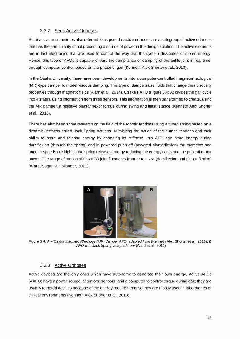
properties through magnetic fields (Alam et al., 2014). Osaka’s AFO (Figure 3.4: A) divides the gait cycle
into 4 states, using information from three sensors. This information is then transformed to create, using
the MR damper, a resistive plantar flexor torque during swing and initial stance (Kenneth Alex Shorter
et al., 2013).
There has also been some research on the field of the robotic tendons using a tuned spring based on a
dynamic stiffness called Jack Spring actuator. Mimicking the action of the human tendons and their
ability to store and release energy by changing its stiffness, this AFO can store energy during
dorsiflexion (through the spring) and in powered push-off (powered plantarflexion) the moments and
angular speeds are high so the spring releases energy reducing the energy costs and the peak of motor
power. The range of motion of this AFO joint fluctuates from 8° to −25° (dorsiflexion and plantarflexion)
(Ward, Sugar, & Hollander, 2011).
Figure 3.4: A – Osaka Magneto Rheology (MR) damper AFO, adapted from (Kenneth Alex Shorter et al., 2013); B
–AFO with Jack Spring, adapted from (Ward et al., 2011)
3.3.3 Active Orthoses
Active devices are the only ones which have autonomy to generate their own energy. Active AFOs
(AAFO) have a power source, actuators, sensors, and a computer to control torque during gait; they are
usually tethered devices because of the energy requirements so they are mostly used in laboratories or
clinical environments (Kenneth Alex Shorter et al., 2013).
A B

20
Their major advantage is their ability to provide net power to the ankle, instead of only storing and
releasing available energy like passive and semi-active devices.
When talking about actuators it cannot be forgotten that actuators do not act instantaneously so they
need to provide the required joint torque with the right speed and frequency response. The biggest
challenge remains the variability and uncertainty of the biomechanics of the human body and the
specificity of the wearer (Cenciarini & Dollar, 2011).
Artificial pneumatic muscles consist of an expandable internal bladder, the volume of which is regulated
like a balloon, so that as the internal volume increases the pneumatic muscle shortens producing
tension. The Michigan’s AFO, was built to study the neuromechanical control of human walking, (Figure
3.5: A) and can produce about 70% of the positive plantar flexor work required in normal walking
(Gordon, Sawicki, & Ferris, 2006).
Another group of scientists developed a Portable Powered Ankle-Foot Orthosis (PPAFO) with plantar
flexor and dorsiflexor torque assistance for daily use (walking function, gait training tool) using a
compressed carbon dioxide bottle as power source (Figure 3.5: B). The PPAFO design has two
separated parts: the power source and regulator and the structural elements. This division was made
taking in account the weight of the device. Its untethered nature would allow in-home rehabilitation (K
Alex Shorter, Kogler, Loth, Durfee, & Hsiao-Wecksler, 2011).
The MIT Biomechatronics group developed an active AFO for people with drop-foot gait, through the
modification of a passive AFO to an active device with a Series Elastic Actuator (SEA). This actuator is
composed by an elastic element in series with a DC motor (Alam et al., 2014). The computer-controlled
motor adjusts the impedance of the AFO’s joint by varying the height of the spring while motion control
of the foot and plantar flexor torque are provided during gait (Herr, 2009), (Kenneth Alex Shorter et al.,
2013). The MIT’s AFO design can be seen in Figure 3.5: C.
A hybrid active AFO, called DACHOR, can be seen in Figure 3.5: D and was developed by researchers
in Instituto Superior Técnico to support general gait impairments and promote the rehabilitation of the
musculo-skeletal system. Its hybrid nature is a reflex of coupling external mechanical actuation
(performed by an SEA with variable impedance) with functional electrical stimulation (Melo,
Vasconcelos, Martins, & Silva, 2011). The actuator has the capability of measuring the external ankle
joint moments, adjusting the power of the device to the requirements of each phase of the gait cycle
(Vasconcelos, Melo, Martins, & Silva, 2013).

21
Figure 3.5: A - Powered AFO with Pneumatic Muscles, adapted from (Gordon et al., 2006), B - Portable-Powered AFO, adapted from (K Alex Shorter et al., 2011), C - MIT active AFO, adapted from (Herr, 2009), D – DACHOR,
adapted from (Melo et al., 2011)
The limitations of active and semi-active orthosis are related with the power limitations and design of
the devices that are usually heavy, noisy and with an unnatural shape (Herr, 2009).
A device with both active and passive functions have advantages from the device’s perspective, since
it would enhance the product and bring a new concept to the market, but also from the wears point of
view. The rehabilitation process is different for each patient and its progression should be assisted by
different types of devices accordingly to the stage of recovery. In an early stage, an active device can
have a crucial role for the patient recovery and, with the evolution of his/her stage, changing for a passive
device would allow an adaptation to his/her needs giving the best possible assistance.
3.4 Market Options
Currently prescribed AFOs are generic and have a standardized size, shape and functional
characteristics, manually fabricated by ortho technicians that need to adjust the AFO to the specific gait
characteristics of each patient. They are all passive AFOs (Schrank & Stanhope, 2011).
To date, active AFOs are only used in laboratories for rehabilitation and research proposes. The major
reasons are elevated costs, lack of clinical improvement evidence, the bulky design of some systems
and the problem of a portable lightweight power supply (Alam et al., 2014), (Díaz, Gil, & Sánchez, 2011),
(K Alex Shorter et al., 2011).
It’s important to note that the leading Orthotics/Prosthetics companies (like Otto Bock health Care and
Becker Orthopaedic) have no multifunctional ankle-foot dynamic orthoses on the market for daily wear
(Milusheva et al., 2007).
There have been great developments in the academic field on this subject but there is a lack of
information regarding the effectiveness of these devices in performing their intended tasks. Instead of
enhance the great developments in this field, the lack of quantitative results of exoskeletons emphasize
the numerous challenges regarding the creation of these devices (Dollar & Herr, 2008).
D C A B

22
23
Chapter 4
4.
Concept Development: from an idea to a in silico working model
When looking to the characteristics of general population it is easy to see that there is an increasing
demographic ageing. This, allied with the higher number of people suffering from stroke, cerebral palsy
and other common pathologies affecting gait, has proved the crucial need to provide technical aid
solutions that are affordable, specific and easy to acquire.
After evaluating the available market options on the ankle-foot orthoses field it was possible to note that
regarding active AFO, no commercial solutions are presently available.
The great advances that have been made in the AAFO field allow a retrospective vision about what
needs to be changed to transform the new discoveries into something appealing. It is in this context that
the idea of creating a modular AFO solution came to be. The concept idea is to create an independent
system easy to adapt to the needs of any specific individual, by any ortho technician at any commercial
workshop, and that can adapt to different types of gait pathologies. The envisaged system, due to its
nature, can have a passive or an active function over the affected structure.
This chapter describes the design evolution process starting on the initial idea or concept, going through
the adjustments, corrections and alterations necessary to get to the final computational working model
that was used in this work to simulate and analyse the motion and behaviour of the envisaged system
and that also provided the basis for its later prototyping.
4.1 Initial Idea
Conventional solution for an articulated AFO is composed of two modular units: the upper member –
that is attached to the leg – and the lower member – which is the support of the foot. The connection
between these two units is made by a couple of hinge joints, usually aligned with the axis of rotation of
the biological joint of the ankle-foot complex.
24
One of the major problems of these type of solutions is that, in order to have a specific device, costume
made to assess each patient special needs, the production process becomes long, complex and
expensive.
In pursuing a solution easier to implement, arises the idea of a modular solution with 3 distinct modules:
the upper and lower members (the same modules existent in the conventional solution) and the action
module. This later module is where the innovation resides, due essentially to two peculiarities: first it
does not require any joint to be connected to the lower part, which facilitates the assembly of the
orthosis; secondly this action module is a product “off-the-shelf”, i.e., the module can be acquired
according to the stature of the patient and its gait impairments and easily mounted at the workshop, to
the upper and lower modules that were made specifically for the wearer morphology.
This leads to an improvement in the area of the AFOs: the action module can be simply attached to the
upper and lower module and only these two parts are specific for each. The action module is set to the
patient requirements through a detailed specification process made online before being acquired, and
after that the only work is to adapt it to the upper and lower members.
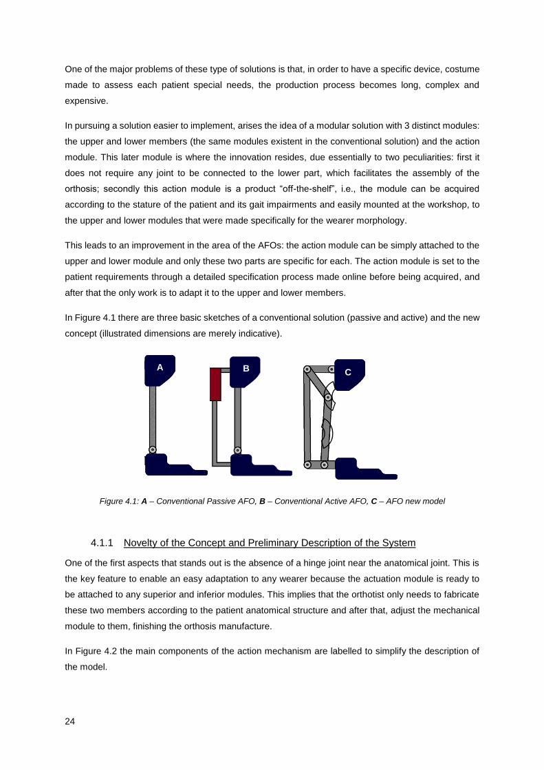
In Figure 4.1 there are three basic sketches of a conventional solution (passive and active) and the new
concept (illustrated dimensions are merely indicative).
Figure 4.1: A – Conventional Passive AFO, B – Conventional Active AFO, C – AFO new model
4.1.1 Novelty of the Concept and Preliminary Description of the System
One of the first aspects that stands out is the absence of a hinge joint near the anatomical joint. This is
the key feature to enable an easy adaptation to any wearer because the actuation module is ready to
be attached to any superior and inferior modules. This implies that the orthotist only needs to fabricate
these two members according to the patient anatomical structure and after that, adjust the mechanical
module to them, finishing the orthosis manufacture.
In Figure 4.2 the main components of the action mechanism are labelled to simplify the description of
the model.
A C B

25
Figure 4.2: Identification of bars and key points
Another interesting peculiarity is how this system is controlled. Let’s start by making a multibody analysis
to the system. Since the mechanism generates motion only in one plane, the analysis is made
considering a 2D model.
As can be seen in Figure 4.2 there are 5 rigid bodies, each body has 3 degrees of freedom (DOF): two
translations along the X and Y axis and one rotation, which means that 3 coordinates are needed to
describe the position and orientation of each rigid body on a 2D dimension. Multiplying the number of
rigid bodies by the number of DOF gives the total number of DOF of the unconstrained system which is
15.
Next, it’s necessary to take into account the constraints imposed by the joints that connect the bars.
Looking to Figure 4.2 it’s possible to identify 6 revolution joints (2 overlapped at point a, 1 at points b, c,
d and e), each one restrains 2 DOF, the two translations, and therefore there are 12 joint constraints.
The number of DOF of the system is calculate by subtracting the number of constraints to number of
DOF, allowing 3 degrees of freedom.
The goal is to create a system that mimics the motion of the ankle joint during gait, which has essentially
only 1 DOF, the dorsi- and plantar flexion. In order to constraint the remaining 2 DOF two new parts
were added to the device: two rails, as can be seen in Figure 4.3.
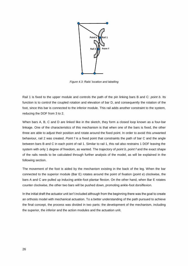
26
Figure 4.3: Rails’ location and labelling
Rail 1 is fixed to the upper module and controls the path of the pin linking bars B and C: point b. Its
function is to control the coupled rotation and elevation of bar D, and consequently the rotation of the
foot, since this bar is connected to the inferior module. This rail adds another constraint to the system,
reducing the DOF from 3 to 2.
When bars A, B, C and D are linked like in the sketch, they form a closed loop known as a four-bar
linkage. One of the characteristics of this mechanism is that when one of the bars is fixed, the other
three are able to adjust their position and rotate around the fixed point. In order to avoid this unwanted
behaviour, rail 2 was created. Point f is a fixed point that constraints the path of bar C and the angle
between bars B and C in each point of rail 1. Similar to rail 1, this rail also restrains 1 DOF leaving the
system with only 1 degree of freedom, as wanted. The trajectory of point b, point f and the exact shape
of the rails needs to be calculated through further analysis of the model, as will be explained in the
following section.
The movement of the foot is aided by the mechanism existing in the back of the leg. When the bar
connected to the superior module (Bar E) rotates around the point of fixation (point e) clockwise, the
bars A and C are pulled up inducing ankle-foot plantar flexion. On the other hand, when Bar E rotates
counter clockwise, the other two bars will be pushed down, promoting ankle-foot dorsiflexion.
In the initial draft the actuator unit isn’t included although from the beginning there was the goal to create
an orthosis model with mechanical actuation. To a better understanding of the path pursued to achieve
the final concept, the process was divided in two parts: the development of the mechanism, including
the superior, the inferior and the action modules and the actuation unit.
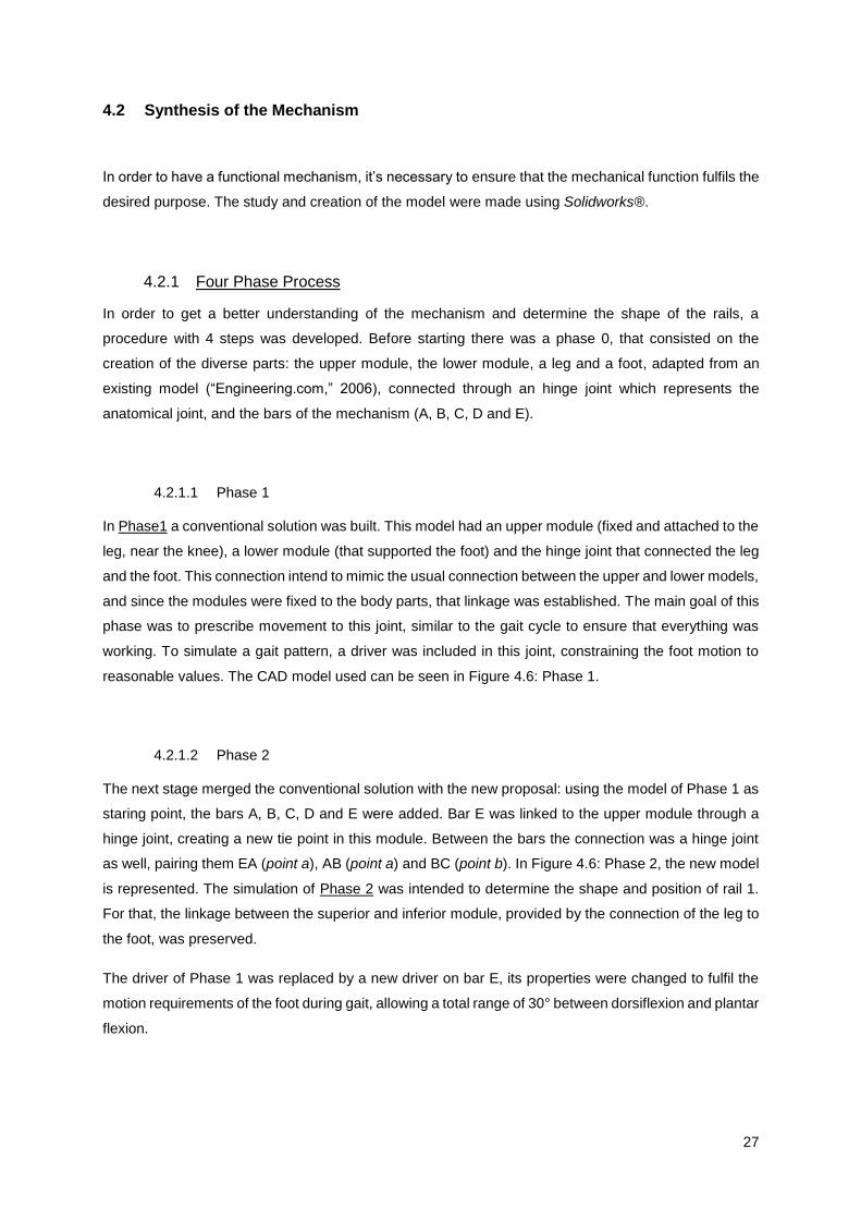
27
4.2 Synthesis of the Mechanism
In order to have a functional mechanism, it’s necessary to ensure that the mechanical function fulfils the
desired purpose. The study and creation of the model were made using Solidworks®.
4.2.1 Four Phase Process
In order to get a better understanding of the mechanism and determine the shape of the rails, a
procedure with 4 steps was developed. Before starting there was a phase 0, that consisted on the
creation of the diverse parts: the upper module, the lower module, a leg and a foot, adapted from an
existing model (“Engineering.com,” 2006), connected through an hinge joint which represents the
anatomical joint, and the bars of the mechanism (A, B, C, D and E).
4.2.1.1 Phase 1
In Phase1 a conventional solution was built. This model had an upper module (fixed and attached to the
leg, near the knee), a lower module (that supported the foot) and the hinge joint that connected the leg
and the foot. This connection intend to mimic the usual connection between the upper and lower models,
and since the modules were fixed to the body parts, that linkage was established. The main goal of this
phase was to prescribe movement to this joint, similar to the gait cycle to ensure that everything was
working. To simulate a gait pattern, a driver was included in this joint, constraining the foot motion to
reasonable values. The CAD model used can be seen in Figure 4.6: Phase 1.
4.2.1.2 Phase 2
The next stage merged the conventional solution with the new proposal: using the model of Phase 1 as
staring point, the bars A, B, C, D and E were added. Bar E was linked to the upper module through a
hinge joint, creating a new tie point in this module. Between the bars the connection was a hinge joint
as well, pairing them EA (point a), AB (point a) and BC (point b). In Figure 4.6: Phase 2, the new model
is represented. The simulation of Phase 2 was intended to determine the shape and position of rail 1.
For that, the linkage between the superior and inferior module, provided by the connection of the leg to
the foot, was preserved.
The driver of Phase 1 was replaced by a new driver on bar E, its properties were changed to fulfil the
motion requirements of the foot during gait, allowing a total range of 30° between dorsiflexion and plantar
flexion.

28
Following the path of point b it was possible to determine the shape of the rail in those conditions. It was
a parabolic-like curve that was after converted into a rail. The curve can be analysed on the first graphic
of Figure 4.4.
4.2.1.3 Phase 3
Phase 3 was design to build rail 2. In contrast to rail 1 that constrained one point to a path, rail 2 is
needed to constrain the path of bar C to pass through a point, hence avoiding the angulation of this bar
around point b. A fixed pin was created (point f) that intersected some points of bar C during motion.
The shape of this bar had to be changed to enclose the rail.
With the same drive and conditions of Phase 2, the intersection of the new pin with bar C was recorded
for every position of the mechanism, forming a curve similar to the path of point b, as can be seen in the
second graphic of Figure 4.4.
Figure 4.4: Displacement (mm) of point b (Z, X) and point f (Z, X)
Analysing the shape of the curves, there seemed to be a relationship between them. The curve of rail 2
looked like a mirrored feature of the curve of rail 1. In order to evaluate if these curves were similar or
had any kind of relation, it required some data processing.
Starting with the first rail’s curve there was a rotation of −𝜋
2 on the data. After this transformation it looked
like a second degree polynomial function, the respective plot is depicted in Figure 4.5. Applying a
polynomial regression of second degree there is a good correlation between the model and the data,
with a 𝑅² = 0.9998 so it was assumed that the curve can be considered a polynomial of second degree.
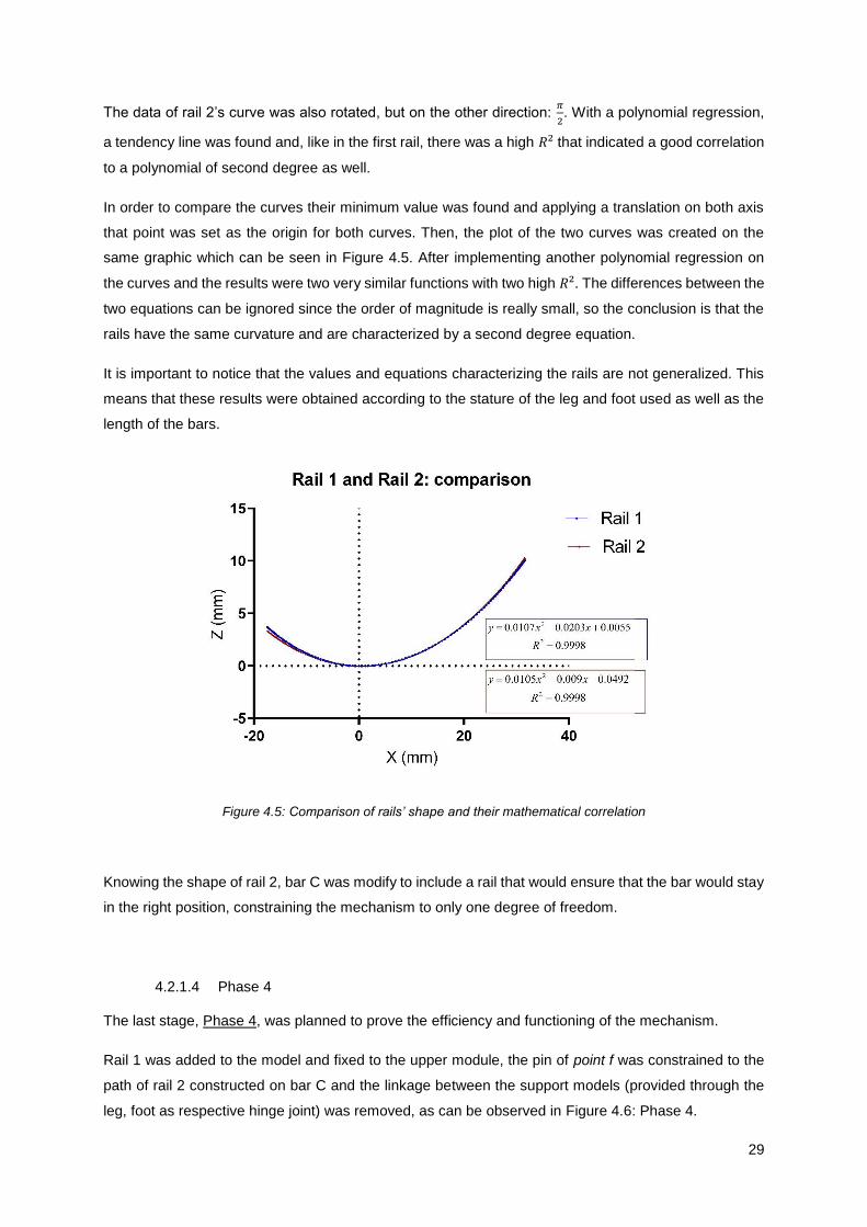
29
The data of rail 2’s curve was also rotated, but on the other direction: 𝜋
2. With a polynomial regression,
a tendency line was found and, like in the first rail, there was a high 𝑅² that indicated a good correlation
to a polynomial of second degree as well.
In order to compare the curves their minimum value was found and applying a translation on both axis
that point was set as the origin for both curves. Then, the plot of the two curves was created on the
same graphic which can be seen in Figure 4.5. After implementing another polynomial regression on
the curves and the results were two very similar functions with two high 𝑅². The differences between the
two equations can be ignored since the order of magnitude is really small, so the conclusion is that the
rails have the same curvature and are characterized by a second degree equation.
It is important to notice that the values and equations characterizing the rails are not generalized. This
means that these results were obtained according to the stature of the leg and foot used as well as the
length of the bars.
Figure 4.5: Comparison of rails’ shape and their mathematical correlation
Knowing the shape of rail 2, bar C was modify to include a rail that would ensure that the bar would stay
in the right position, constraining the mechanism to only one degree of freedom.
4.2.1.4 Phase 4
The last stage, Phase 4, was planned to prove the efficiency and functioning of the mechanism.
Rail 1 was added to the model and fixed to the upper module, the pin of point f was constrained to the
path of rail 2 constructed on bar C and the linkage between the support models (provided through the
leg, foot as respective hinge joint) was removed, as can be observed in Figure 4.6: Phase 4.
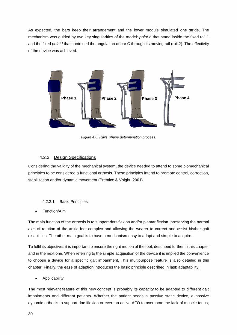
30
As expected, the bars keep their arrangement and the lower module simulated one stride. The
mechanism was guided by two key singularities of the model: point b that stand inside the fixed rail 1
and the fixed point f that controlled the angulation of bar C through its moving rail (rail 2). The effectivity
of the device was achieved.
Figure 4.6: Rails’ shape determination process.
4.2.2 Design Specifications
Considering the validity of the mechanical system, the device needed to attend to some biomechanical
principles to be considered a functional orthosis. These principles intend to promote control, correction,
stabilization and/or dynamic movement (Prentice & Voight, 2001).
4.2.2.1 Basic Principles
Function/Aim
The main function of the orthosis is to support dorsiflexion and/or plantar flexion, preserving the normal
axis of rotation of the ankle-foot complex and allowing the wearer to correct and assist his/her gait
disabilities. The other main goal is to have a mechanism easy to adapt and simple to acquire.
To fulfil its objectives it is important to ensure the right motion of the foot, described further in this chapter
and in the next one. When referring to the simple acquisition of the device it is implied the convenience
to choose a device for a specific gait impairment. This multipurpose feature is also detailed in this
chapter. Finally, the ease of adaption introduces the basic principle described in last: adaptability.
Applicability
The most relevant feature of this new concept is probably its capacity to be adapted to different gait
impairments and different patients. Whether the patient needs a passive static device, a passive
dynamic orthosis to support dorsiflexion or even an active AFO to overcome the lack of muscle tonus,
Phase 1 Phase 2 Phase 3 Phase 4

31
all these configurations are achievable with this concept. The same mechanism can be adapted and
adjusted to the uniqueness of each case. Description of the applications of the device is made in the
next sub-chapter 4.3 Actuation Unit.
Usability
It is always important to take into account the practical issues of wearing and prescribing an AFO.
On the one hand there is the likeliness of the device from the wearer. An affinity feeling must be
encourage to ease the process of adaptation to the device and of awareness of the need for such
technical aid. Some relevant feature relative to the exterior design of the device are presented in the
last topic of this sub-chapter.
Achieving the functions considered for the device and analysing real life situations where the device can
be used is the final step to conclude concept’ development. This device have the potential to be used in
three different environments: rehabilitation session, home recovery, and daily use. Each environment
has its peculiarities and some adaptation may be needed to fulfil them but it is important to acknowledge
these possible scenarios to understand the full potential of the developed AFO.
Adaptability
One relevant feature is the connection of the action module to the upper and lower members. The
connection to the lower member requires special attention since the device is intended to be used with
shoes, so the connection must not interfere with footwear. This connection is detailed in the end of this
chapter.
An important consideration is the positioning of the device axis. The orthosis must be designed so that
the mechanical axis of the device is coincident to the anatomical axis of the joint. Otherwise undesirable
forces tend to be generated (Kaufman & Irby, 2006).
As explained in Chapter 2, the anatomical axis joint has a deviation in relation to frontal plane.
To align the device with this joint, the device should be placed with a slight rotation around the leg,
instead of being aligned in the centre of the leg. This correction is made through the connection of the
support to the upper module, as will be detailed further.
4.2.2.2 Four-Bar Linkage Mechanism
Looking to the mechanism is easy to identify a closed chain of four bars. This is a common mechanism
called four bar linkage. A simplified model of this mechanism can be seen in Figure 4.7.
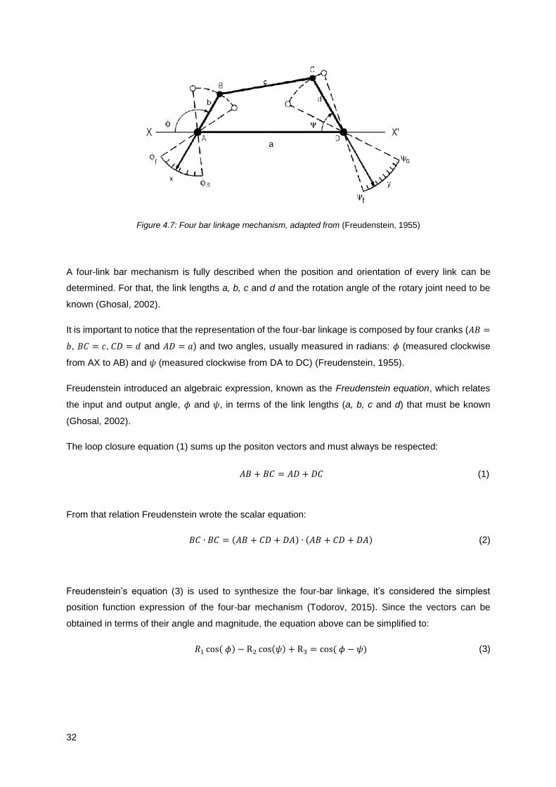
32
Figure 4.7: Four bar linkage mechanism, adapted from (Freudenstein, 1955)
A four-link bar mechanism is fully described when the position and orientation of every link can be
determined. For that, the link lengths a, b, c and d and the rotation angle of the rotary joint need to be
known (Ghosal, 2002).
It is important to notice that the representation of the four-bar linkage is composed by four cranks (𝐴𝐵 =
𝑏, 𝐵𝐶 = 𝑐, 𝐶𝐷 = 𝑑 and 𝐴𝐷 = 𝑎) and two angles, usually measured in radians: 𝜙 (measured clockwise
from AX to AB) and 𝜓 (measured clockwise from DA to DC) (Freudenstein, 1955).
Freudenstein introduced an algebraic expression, known as the Freudenstein equation, which relates
the input and output angle, 𝜙 and 𝜓, in terms of the link lengths (a, b, c and d) that must be known
(Ghosal, 2002).
The loop closure equation (1) sums up the positon vectors and must always be respected:
𝐴𝐵 + 𝐵𝐶 = 𝐴𝐷 + 𝐷𝐶 (1)
From that relation Freudenstein wrote the scalar equation:
𝐵𝐶 ∙ 𝐵𝐶 = (𝐴𝐵 + 𝐶𝐷 + 𝐷𝐴) ∙ (𝐴𝐵 + 𝐶𝐷 + 𝐷𝐴) (2)
Freudenstein’s equation (3) is used to synthesize the four-bar linkage, it’s considered the simplest
position function expression of the four-bar mechanism (Todorov, 2015). Since the vectors can be
obtained in terms of their angle and magnitude, the equation above can be simplified to:
𝑅1 cos( 𝜙) − R2 cos(𝜓) + R3 = cos ( 𝜙 − 𝜓) (3)
a

33
Where,
𝑅1 =
𝑑
𝑐
(4)
𝑅2 =
𝑑
𝑎
(5)
𝑅3 =
𝑎2 + 𝑐2 + 𝑑2 − 𝑏2
2𝑎𝑐
(6)
The kinematical relationship between 𝜙 and 𝜓 is not affected by the overall size of the linkage as long
as the relationship between the links is preserved. So it is possible to set one of the link dimensions to
1 and in the end scale up the other link lengths (Freudenstein, 1955), (Todorov, 2015).
Through equation (3) the output angle 𝜓 can be calculated for a known input angle 𝜙 and links length.
With this equation it’s also possible to establish the length of the link bars, for a known range of 𝜙i and
𝜓𝑖, this is called: Precision Point Design (Freudenstein, 1955). With 𝑖 in a range from 1 to 3, one can
substitute these angles in equation (3) and obtain three linear equations 𝑅1, 𝑅2 and 𝑅3 and estimate the
link lengths b, c and d.
Using Freudenstein’s Method it is possible to optimize the dimensions of the orthosis mechanism. The
same strategy was used in 2007 to build a passive orthosis for locomotor rehabilitation (Berkelman,
Rossi, Lu, & Ma, 2007).
A Matlab routine was implemented and the required angle values were obtained through the
Solidworks® model. The three precision points chosen represented the peak of dorsiflexion, plantar
flexion and a neutral position. An arbitrary value of 1 was chosen to the length 𝑎, since it could be later
changed to a reasonable value, scaling up the whole model. The generated values were used to correct
the model to a more compact configuration.
4.2.2.3 Range of Motion
The purpose of the orthosis is to aid plantar flexion and dorsiflexion during gait, the normal range of
motion of the ankle-foot complex is 30º, as stated in Chapter 2.
Taking in account that the principal goal of the use of this orthosis is for gait rehabilitation, these were
the limits imposed on the device: 15º for dorsiflexion and 15º for plantar flexion. The characteristics of
the driver were adjusted to fulfil the needs of walking. In Figure 4.8 the limits of motion are established
by three reference planes represented in green, it’s also possible to see the movement of the foot within
those limits.

34
Figure 4.8: Orthosis model and limits of motion: A – neutral (0º); B – Dorsiflexed (15º); C – Plantar flexed (15º)
4.2.2.4 Uncanny valley
The design of a device (prosthesis, orthosis, robot and other) especially its resemblance with human
beings have implications for human-robot interaction. If there is a lack of resemblance to human beings
people don’t feel any affinity, however if the device have a more humanlike appearance it induces a
heightened sense of affinity (Mori, 1970).
The Uncanny Valley describes the relation between the human likeness of an entity and the perceiver’s
affinity for it, the curve that illustrates this association is represented in Figure 4.9.
Figure 4.9: The Uncanny Valley, adapted from (Mori, 1970)
The presence of movement on these devices amplifies the peaks and valleys. So, the best solution is a
moderate degree of human likeness with a considerable sense of affinity.
In order to create an attractive device, these aspects were taking into account. The shape of bar A, that
is the bar furthest from the leg, was design to mimic the silhouette of a human leg. This detail had not
only a visual purpose but was intended to reduce the area occupied by the mechanism.
A B C

35
Another important detail is that the mechanism was design to be concentrated on the upper zone of the
device. This has two advantages: first this way it’s possible to enclosure the mechanism inside of a box,
keeping the modular concept, and second, the major weight of the device is centralize on the proximal
portion of the leg. Placing most of the device’s weight to a superior part of the leg, the cost of walking is
minimized, since the moment arm of the device in relation to the nearest joint is decreased (P. C. Silva,
Silva, & Martins, 2010).
4.3 Actuation Unit
Once the mechanism is fully described and characterized, the next step is to detail the attributes of the
device. There are two aspects to discuss in terms of the mechanical function of the orthosis: the type
and the actuation of the device.
4.3.1 Duality: Articulated and Non-Articulated
One of the particularities of this design is that the orthosis can be articulated, enabling the normal motion
of the foot or non-articulated, securing the neutral position of the foot. This duality provide the ability to
adjust the device to many purposes, according to the wearers needs, the type of pathology and the state
of recovery.
To allow this double function two parts were add to the linkage of the bars at point a, one on each
exterior side of the connection. On the support unit there are four connection points, two on the superior
zone, above the link of bar E to the unit and two on the inferior area, near the end of rail 1. These
elements can be seen in Figure 4.10. The key feature is in how these two new bars are attached to the
connection points of the support unit.
Figure 4.10: Support unit (left) and connection bars (right)
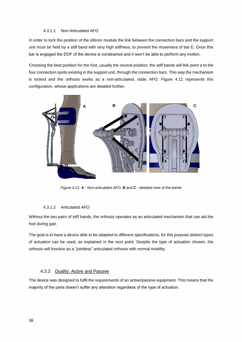
36
4.3.1.1 Non-Articulated AFO
In order to lock the position of the inferior module the link between the connection bars and the support
unit must be held by a stiff band with very high stiffness, to prevent the movement of bar E. Once this
bar is engaged the DOF of the device is constrained and it won’t be able to perform any motion.
Choosing the best position for the foot, usually the neutral position, the stiff bands will link point a to the
four connection spots existing in the support unit, through the connection bars. This way the mechanism
is locked and the orthosis works as a non-articulated, static AFO. Figure 4.11 represents this
configuration, whose applications are detailed further.
Figure 4.11: A - Non-articulated AFO, B and C - detailed view of the bands
4.3.1.2 Articulated AFO
Without the two pairs of stiff bands, the orthosis operates as an articulated mechanism that can aid the
foot during gait.
The goal is to have a device able to be adapted to different specifications, for this purpose distinct types
of actuation can be used, as explained in the next point. Despite the type of actuation chosen, the
orthosis will function as a “jointless” articulated orthosis with normal mobility.
4.3.2 Duality: Active and Passive
The device was designed to fulfil the requirements of an active/passive equipment. This means that the
majority of the parts doesn’t suffer any alteration regardless of the type of actuation.
A B C

37
Although, there are a few features that need to be changed. The adaption to an active device implies
changes on the connection bars, which are replace by one bar with an horseshoe arc that connects
point a to the actuator. In Figure 4.12 the two kinds of connections used are represented.
Figure 4.12: A – Connection bar of the active solution; B – Connection bar of the passive solution
The box that enclosures the mechanism must be replaced by another box, with the necessary
dimensions to embody the actuator (see section 4.4.1). The support unit also needs to be replaced by
one with a bearing bracket to attach the actuator. Remain parts are common for both solutions.
4.3.2.1 Passive Orthosis
With the use of connection elements with different stiffnesses and elastic characteristics, it’s possible to
adjust the device to diverse stages of rehabilitation as well as to various pathologies.
In some cases disabilities affect plantar flexion, on other cases dorsiflexion and in some situation both
movements. Gait impairments can result from neurologic or musculoskeletal causes and each disorder
needs a specific device, adjusted to the degree of the disorder and the type of aid needed. This can be
translated into different configurations of the orthosis, to address the specificity of each patient.
The device’s multitasking nature allows the adaptation to the patient best interest. To fulfil the
requirements of each disability, there are different connection elements that can be used coupled with
the selection of the correct location site.
There are three types of connection elements: elastic bands, stiff bands and springs; and two connection
sites: the top and bottom sites, both localized on the support unit. The value of the mechanical
characteristics of the elements such as stiffness is another variable when talking about passive dynamic
orthotics.
Hooke’s law or law of elasticity states that the displacement or deformation (∆𝑥) of an object is directly
proportional to the deforming force or load (�⃗�), as expressed in the next equation:
�⃗� = 𝐾∆𝑥 (7)
B A
38
The constant 𝐾 represents the material property: stiffness. This constant can be chosen accordingly to
the function of the element, for instance, the elastic and stiff bands are the same element but with very
different values for 𝐾, the stiff band has very high stiffness to act like an inelastic band.
In this case the deformation or displacement ∆𝑥 represents the variation of element’s length. The main
difference between the spring and the bands is that this variation can be positive and negative for the
spring, because there is storing of energy when the force is applied on both directions and the bands
only have positive variation of length, since there is only storing of energy when the force is applied in
this direction. Conjugating two pair of elastic bands, placed on both upper and lower sites, it is possible
to get the same result of using one pair of springs, regardless of the connection point. This happens
because the compression and stretching of the spring can be compared to the stretching of the elastic
bands, one pair for the positive and the other for the negative variation of the spring length.
There are many possible configurations conjugating one connection element, one point of connection
and the value for the stiffness. The different situations and their description and application are
represented on Table 4.1. There are other possible configurations mixing the types of elements used
that are not represented.
The stiff band has a very high value of 𝐾 so the force required to cause a change in the length is so high
that the possible length variation is insignificant. With this connection element, there are only three
possible configurations, which differ on the link site of the band. They are represented on Table 4.1, first
element.
When there are two pairs of stiff bands, linked on both sites of the support, the device acts like a non-
articulated orthosis. The bands lock any possible motion, as described in the previous section.
Making the linkage of the band to the lower site will prevent plantar flexion allowing the normal range of
dorsiflexion. The band must be streched at neutral position and will restrain the motion of bar E to a
higher position. This can be used to limit the drop of the foot since the band acts against the gravity
force.
If the band is attacted to the superior site the device will prevent dorsiflexion. This situation is not usefull
since dorsiflexion plays a major role during gait, so this configuration should not be used.
Elastic bands can be applied in the same locations as the stiff bands however, different solutions can
be created if the stiffness of the bands is changed and according to which position of the foot
corresponds the normal configuration of the elastic bands. The third collum of Table 4.1 contains three
possible configurations of the device when using elastic bands.
If the connection is made at the top of the support, and assuming that the inderformable configuration
of the elastic band correspond to the maximum of plantar flexion, the device will prevent dorsiflexion,
supporting plantar flexion. This is the natural reaction of the decive when exposed to the gravitional
forces, because when the muscles aren’t working the foot relaxes embracing a plantar flexed
configuration. This solution would be usefull on a rehabilitation environment where the goal is to recover

39
Table 4.1: Passive actuation components and respective response
ELEMENT Stiff Band Elastic Band Spring
LOCATION
FUNCTION Up Down Both Up Down Both Not applicable
Prevent Dorsiflexion X X X
Prevent Plantar Flexion X X X
Support Dorsiflexion X X X
Support Plantar Flexion
X X X
DESCRIPTION
Prevent
dorsiflexion,
allow plantar
flexion
Prevent
plantar
flexion, allow
dorsiflexion
Prevent
dorsiflexion
and plantar
flexion
Promote
plantar
flexion,
oppose
dorsiflexion
Promote
dorsiflexion,
oppose
plantar
flexion
Controlled
dorsiflexion,
elastic bands
with different
stiffness
Controlled
dorsiflexion/plantar
flexion, storing of
energy during plantar
flexion/dorsiflexion
CIRCUMSTANCES Not
applicable
Prevent drop
foot
Fixed Foot
(passive,
non-
articulated
AFO)
Rehabilitation
of the
dorsiflexor
muscles,
prevent foot
slap
Prevent drop
foot and toe
dragging
Prevent drop
foot: foot
slap and toe
dragging
Prevent drop foot and
foot slap, ensure toe
clearance
40
the dorsiflexor muscles through a specific training, working against the elasctic force. It is also appliable
to prevent foot slap because the device imposes a controlled dorsiflexion.
When the lower site is chosen and considering that the normal length of the band is set to maximum of
dorsiflexion, the device will promote toe clearance during gait, as well as prevent drop foot. There will
be controlled dorsiflexion and plantar flexion will occur against the strength of the band. The value of
stiffness can’t be too high to ensure that it doesn’t interfere with normal plantar flexion.
The use of two pairs of elastic bands allows a choice of different stiffness values for each pair. Thus one
pair plays the main role while the other only supports motion. For instance, if the pair with higher stiffness
is locked to the bottom site, at the middle of dorsiflexion and the other pair, with lower stiffness, at the
middle of plantar flexion the device will promote controlled dorsiflexion and assist plantar flexion. The
focus is on dorsiflexion for two reasons: first to avoid drop foot and second because plantar flexion
occurs more easily through the action of gravity.
When both pairs have the same stiffness values the elastic bands can be replaced by one pair of springs,
with the same stiffness. This way, for the same purpose, the device has a simplified configuration that
can be advantageous, in terms of space, material and assembly process.
Since the use of one pair of springs is equivalent to use two pairs of elastic bands with the same stiffness,
the point of connection of this element is not relevant to the action of the device. The same effect will be
achieved connecting the springs to the upper or lower sites.
There are only two variables to consider when using springs, one of them is the value chosen for
stiffness and the other one is to which the position of the foot corresponds the natural configuration of
the spring. In the last column of Table 4.1 the possible configurations with the use of springs are
represented. It is important to notice that with the same location site and the same stiffness it is possible
to have two different configurations where only the position of the foot for the normal spring length is
changed.
When the resting length in coinciding with the beginning of dorsiflexion, the device will prevent drop foot
gait. When the foot touches the ground, the device is working against the spring, reducing its length and
storing energy, with the help of body weight. At the end of stance phase, after push off, the spring
releases its energy supporting dorsiflexion and assuring toe clearance. This configuration will also
prevent foot slap because at the beginning of the stance phase, the foot is working against the spring
promoting controlled contact with the ground.
Establishing the normal length to the beginning of plantar flexion can be useful in rehabilitation
environments. With this configuration the wearer will be working against the spring during dorsiflexion;
the stored energy is released when this action stops and the foot returns to a plantarflexed position. If
the wearer continues the motion until the peak of plantarflexion, the stored energy is latter released
promoting the beginning of dorsiflexion.
41
It is also possible to conjugate different kind of elements so that they work together. For instance,
another configuration could be done with a stiff band placed at the lower site, constraining the degree
of plantar flexion allowed and linking an elastic band to the upper site to promote dorsiflexion. This
configuration would prevent toe dragging, since plantar flexion in restrained as well as assist dorsiflexion
during swing phase.
4.3.2.2 Active Orthosis
An active solution implies the use of an actuator, usually encompassing an engine and an energy
source. It also needs sensors to control the action of the actuator, so that it works according to each
stage of the gait cycle, otherwise it would continuously promote dorsiflexion/plantar flexion regardless
of the wearers dynamics and needs.
Active solutions usually have these sensors placed on the sole of the lower member (K Alex Shorter et
al., 2011), which implies that the control is strictly dependent of this module. That’s why active orthoses
are highly dependent on research centres, as it is only after the completely assembly of the orthosis that
the control of the actuator is adjusted.
In this new concept, the control of the actuator would be related to the position of Bar E. The sensor
would be placed in the action unit and the control of the motion and actuator would be included in this
feature, and is independent of patient-specific modules. After acquiring the right model of the orthosis,
with the specifications of the patient, the orthotist only needs to attach this unit to the other modules.
And the actuator, control, sensors and energy source are already incorporated.
Adapting the passive orthosis into an active device implied some design changes, since the actuator
needs a support and must remain inside the cover. The actuator will replace the driver used in the CAD
simulation, controlling the motion of bar E, so it must be placed above the link site of this bar to the
support unit.
One of the requisites of the actuator was that it needed to be a compact solution and have variable
impedance, in order to create the best response to the wearers needs on each phase of the gait cycle.
In 2005, Hollander K. et. al. developed an adjustable robotic tendon that uses the properties of a spring
to simulate a human tendon, it’s called Jack Spring (Sugar & Hollander, 2011) .
The desirable actuator should be develop in the future and could be based on their work; the operation
and characteristics of this mechanism are explained next.
The main goal in wearable robotic systems is to supply high power with low energy in a lightweight
actuator. The idea is to mimic the human capability to control muscle and tendon springs to achieve
high power as well as store and release energy when needed (Ward et al., 2011).
The concept of a Jack Spring relies on power reducing springs and in their inherent elastic nature to
have a controlled stiffness structure trough the addiction or subtraction of the number of active coils.
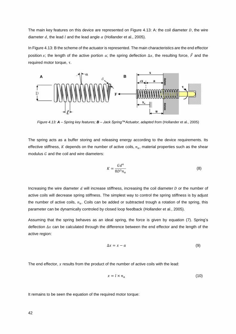
42
The main key features on this device are represented on Figure 4.13: A: the coil diameter 𝐷, the wire
diameter 𝑑, the lead 𝑙 and the lead angle 𝛼 (Hollander et al., 2005).
In Figure 4.13: B the scheme of the actuator is represented. The main characteristics are the end effector
position 𝑥; the length of the active portion 𝑎; the spring deflection ∆𝑥, the resulting force, �⃗� and the
required motor torque, τ.
Figure 4.13: A – Spring key features; B – Jack Spring™Actuator, adapted from (Hollander et al., 2005)
The spring acts as a buffer storing and releasing energy according to the device requirements. Its
effective stiffness, 𝐾 depends on the number of active coils, 𝑛𝑎, material properties such as the shear
modulus 𝐺 and the coil and wire diameters:
𝐾 =𝐺𝑑4
8𝐷3𝑛𝑎
(8)
Increasing the wire diameter 𝑑 will increase stiffness, increasing the coil diameter 𝐷 or the number of
active coils will decrease spring stiffness. The simplest way to control the spring stiffness is by adjust
the number of active coils, 𝑛𝑎. Coils can be added or subtracted trough a rotation of the spring, this
parameter can be dynamically controled by closed loop feedback (Hollander et al., 2005).
Assuming that the spring behaves as an ideal spring, the force is given by equation (7). Spring’s
deflection ∆𝑥 can be calculated through the difference between the end effector and the length of the
active region:
∆𝑥 = 𝑥 − 𝑎 (9)
The end effector, 𝑥 results from the product of the number of active coils with the lead:
𝑥 = 𝑙 × 𝑛𝑎 (10)
It remains to be seen the equation of the required motor torque:
A B
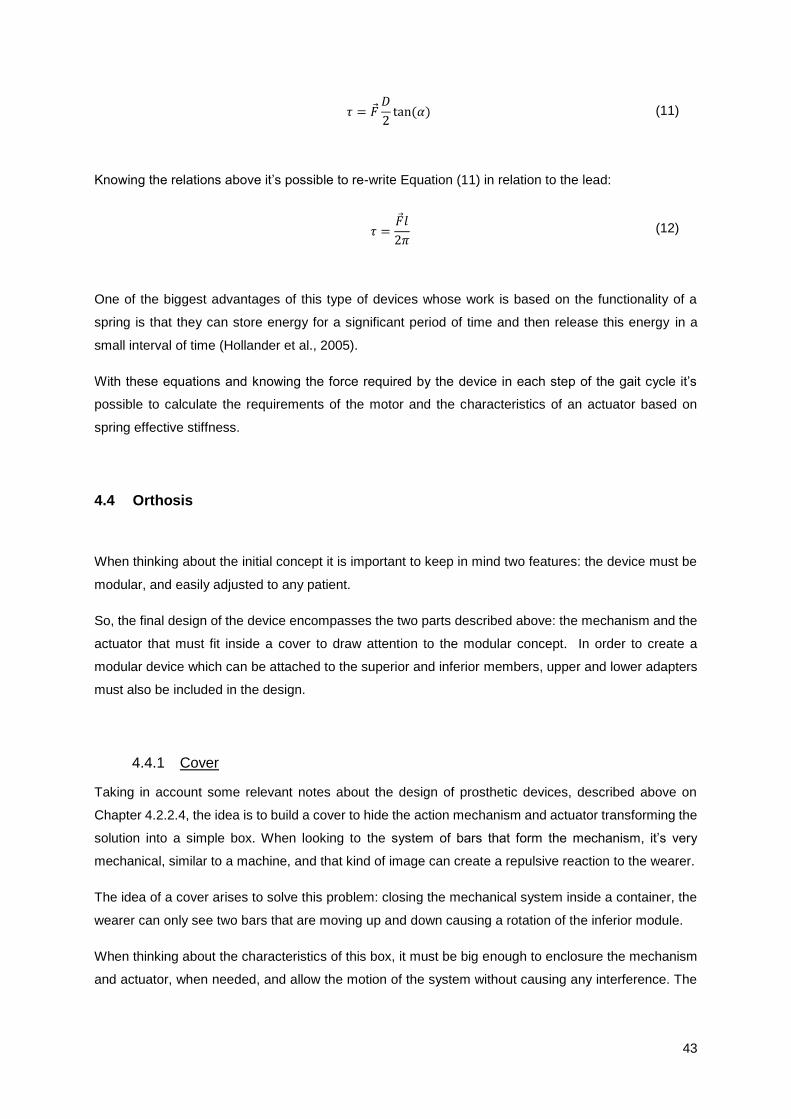
43
𝜏 = �⃗�𝐷
2tan (𝛼) (11)
Knowing the relations above it’s possible to re-write Equation (11) in relation to the lead:
𝜏 =�⃗�𝑙
2𝜋 (12)
One of the biggest advantages of this type of devices whose work is based on the functionality of a
spring is that they can store energy for a significant period of time and then release this energy in a
small interval of time (Hollander et al., 2005).
With these equations and knowing the force required by the device in each step of the gait cycle it’s
possible to calculate the requirements of the motor and the characteristics of an actuator based on
spring effective stiffness.
4.4 Orthosis
When thinking about the initial concept it is important to keep in mind two features: the device must be
modular, and easily adjusted to any patient.
So, the final design of the device encompasses the two parts described above: the mechanism and the
actuator that must fit inside a cover to draw attention to the modular concept. In order to create a
modular device which can be attached to the superior and inferior members, upper and lower adapters
must also be included in the design.
4.4.1 Cover
Taking in account some relevant notes about the design of prosthetic devices, described above on
Chapter 4.2.2.4, the idea is to build a cover to hide the action mechanism and actuator transforming the
solution into a simple box. When looking to the system of bars that form the mechanism, it’s very
mechanical, similar to a machine, and that kind of image can create a repulsive reaction to the wearer.
The idea of a cover arises to solve this problem: closing the mechanical system inside a container, the
wearer can only see two bars that are moving up and down causing a rotation of the inferior module.
When thinking about the characteristics of this box, it must be big enough to enclosure the mechanism
and actuator, when needed, and allow the motion of the system without causing any interference. The
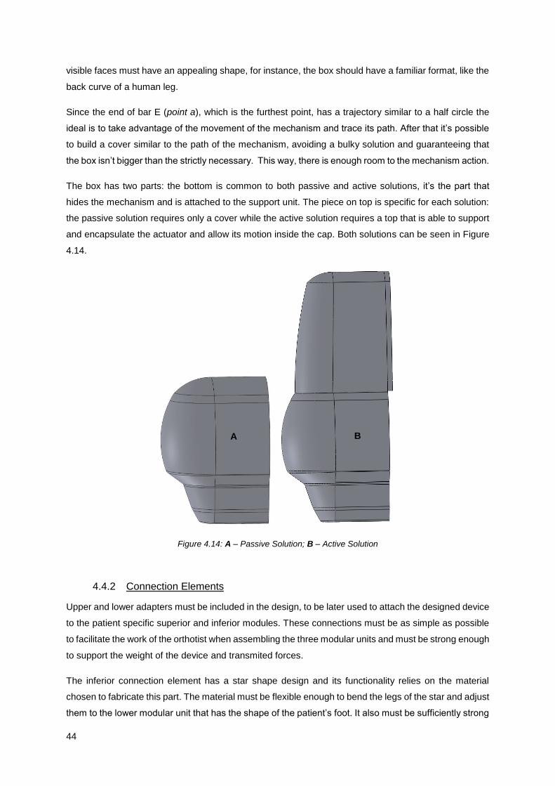
44
visible faces must have an appealing shape, for instance, the box should have a familiar format, like the
back curve of a human leg.
Since the end of bar E (point a), which is the furthest point, has a trajectory similar to a half circle the
ideal is to take advantage of the movement of the mechanism and trace its path. After that it’s possible
to build a cover similar to the path of the mechanism, avoiding a bulky solution and guaranteeing that
the box isn’t bigger than the strictly necessary. This way, there is enough room to the mechanism action.
The box has two parts: the bottom is common to both passive and active solutions, it’s the part that
hides the mechanism and is attached to the support unit. The piece on top is specific for each solution:
the passive solution requires only a cover while the active solution requires a top that is able to support
and encapsulate the actuator and allow its motion inside the cap. Both solutions can be seen in Figure
4.14.
Figure 4.14: A – Passive Solution; B – Active Solution
4.4.2 Connection Elements
Upper and lower adapters must be included in the design, to be later used to attach the designed device
to the patient specific superior and inferior modules. These connections must be as simple as possible
to facilitate the work of the orthotist when assembling the three modular units and must be strong enough
to support the weight of the device and transmited forces.
The inferior connection element has a star shape design and its functionality relies on the material
chosen to fabricate this part. The material must be flexible enough to bend the legs of the star and adjust
them to the lower modular unit that has the shape of the patient’s foot. It also must be sufficiently strong
A B
45
to transmit and support the torque and forces of the action mechanism, causing the rotation of the foot.
This part is also connected to bar D which will propagate the required torque. The connections to bar D
and to the lower modular unit should be made through rivets, to avoid alterations to the exterior face of
the parts. This connection can’t interfere with footwear, since orthoses are meant to be wear in the daily-
life and for that, the wearer need to be able to wear shoes.
On the left side of Figure 4.15 is represented the inferior connection: on the top there is bar D attached
to the connection that has the shape of the inferior module and on the bottom is a simple representation
of the inferior unit before acquiring the shape of the foot.
Superior connection was designed with a double hook configuration. This adapter is attached to the
superior module through its four claws and has plane side on the centre that will lock the support in the
right place. The choice of the material should take in account that it needs to have some flexibility to
bend around the superior module, shaped like the wearers’ leg and need to support the body of the
mechanism. In Figure 4.15 the superior adapter is displayed, on the right.
The proposed shapes are merely indicative and serve only to illustrate the function of these parts in the
proposed design. Their final functional shape requires further research and is therefore outside the
scope of this work.
Figure 4.15: Left: Bar D with inferior connection and the inferior connection; Right: superior connection

46
47
Chapter 5
5.
Mechanical and Technical Design Considerations
With the concept fully developed is time to pay attention to constructive details and mechanical
engineering design to build a functional prototype able to fulfil the requirements of a proof of concept.
Once again the device is divided in mechanism and actuator. The first is fully characterized, with every
part being functionally and mechanically detailed; the actuator unit only works as model for space and
volume considerations, without englobing any actuator function.
The global assembly is also described, as well as the mechanical details required to construct a real
and functional orthosis. The simulation of motion allows further functional analyses together with the
manufacture of a prototype through 3D printing.
5.1 Mechanism
This section highlights some constructive and mechanical details, required to assemble the mechanism
and ensure its proper function. The mechanism can be divided into two sub-groups of parts: bars and
support unit.
5.1.1 Bars
The orthosis has five bars that are responsible for the motion of the foot. Bars A to D form the four bar
linkage and Bar E connects this structure to the support unit. The specifications of each bar are
represented in Table 5.1.
The values chosen for the thickness of the bars did not rely on results of structural analyses because
such step was not in the framework of this project. In order to validate these values, such analysis should
be made in the future.
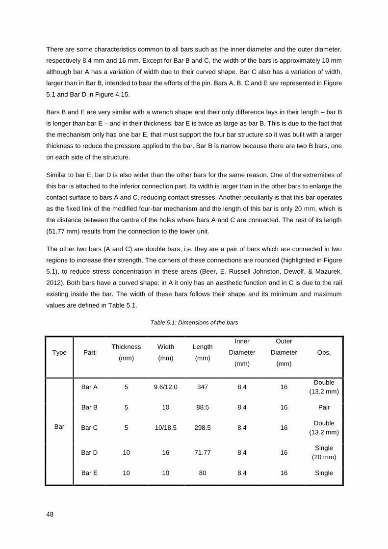
48
There are some characteristics common to all bars such as the inner diameter and the outer diameter,
respectively 8.4 mm and 16 mm. Except for Bar B and C, the width of the bars is approximately 10 mm
although bar A has a variation of width due to their curved shape. Bar C also has a variation of width,
larger than in Bar B, intended to bear the efforts of the pin. Bars A, B, C and E are represented in Figure
5.1 and Bar D in Figure 4.15.
Bars B and E are very similar with a wrench shape and their only difference lays in their length – bar B
is longer than bar E – and in their thickness: bar E is twice as large as bar B. This is due to the fact that
the mechanism only has one bar E, that must support the four bar structure so it was built with a larger
thickness to reduce the pressure applied to the bar. Bar B is narrow because there are two B bars, one
on each side of the structure.
Similar to bar E, bar D is also wider than the other bars for the same reason. One of the extremities of
this bar is attached to the inferior connection part. Its width is larger than in the other bars to enlarge the
contact surface to bars A and C, reducing contact stresses. Another peculiarity is that this bar operates
as the fixed link of the modified four-bar mechanism and the length of this bar is only 20 mm, which is
the distance between the centre of the holes where bars A and C are connected. The rest of its length
(51.77 mm) results from the connection to the lower unit.
The other two bars (A and C) are double bars, i.e. they are a pair of bars which are connected in two
regions to increase their strength. The corners of these connections are rounded (highlighted in Figure
5.1), to reduce stress concentration in these areas (Beer, E. Russell Johnston, Dewolf, & Mazurek,
2012). Both bars have a curved shape: in A it only has an aesthetic function and in C is due to the rail
existing inside the bar. The width of these bars follows their shape and its minimum and maximum
values are defined in Table 5.1.
Table 5.1: Dimensions of the bars
Type Part Thickness
(mm)
Width
(mm)
Length
(mm)
Inner
Diameter
(mm)
Outer
Diameter
(mm)
Obs.
Bar
Bar A 5 9.6/12.0 347 8.4 16 Double
(13.2 mm)
Bar B 5 10 88.5 8.4 16 Pair
Bar C 5 10/18.5 298.5 8.4 16 Double
(13.2 mm)
Bar D 10 16 71.77 8.4 16 Single
(20 mm)
Bar E 10 10 80 8.4 16 Single

49
5.1.2 Support Unit
The support unit has an irregular shape, built on a rectangle with 146.20 mm high and 102.30 mm width.
The backward face is a plane surface and all the embossed elements are constructed on the front face.
This part plays an important role in the mechanism as it is part of six different features essential for the
function of the device. Its sketch is represented in Figure 5.1 where the functional elements are
numbered.
As the name implies, two of these features have a bearing function since this part is the attachment site
for the device, through bar E, and for the superior connection that is made at the back of the unit.
Bar E is attached in the middle of the bearing brackets, which define the revolution joint, through a
screw. This connection must allow the rotation of the bar around the axis of the bearing brackets, and
is represented in Figure 5.1 with the number 2. The superior connection is fixed on the back of the unit
through the holes labelled with the number 3 in Figure 5.1 .
This part is also the link site of the connection elements described in section 4.3.2.1; the four bearing
brackets (number 1) have the same dimensions and each pair is placed at the same distance from the
centre of the part, which is the location of the connection bars on point a.
Another important feature is rail 1, labelled as number 4 in Figure 5.1. This feature plays a major role in
constraining the motion of the mechanism. This feature is as wider as the sleeve of point b, to avoid
gaps between the surfaces that will affect the restrain of the degree of freedom, hindering the action of
the device.
The pin at point f, represented by the number 6 of Figure 5.1, is placed bellow rail 1 and is built to be a
perfect fit in Rail 2. Rail 2 is not part of the support unit but it will slide along this pin assuring the right
angulation of the device.
The last feature is the perfect fitting of the box around the internal edge. Like in bars A and C, the corners
of the edge are round to reduce stress concentration. To fix the box, four holes were made aligned with
holes of the box, to insert the fixing screws. The top of the unit, above the internal edge, acts as a jamb
for the cover of the box. These details can be seen in Figure 5.1, number 5.

50
Figure 5.1: Bars and support unit; highlight of the curved corners and numbering of the support’s features: A – bar
A; B – bar B; C – bar C; E – bar E; 1 – link sites of the connection elements; 2 – bearing brackets for bar E; 3 –
slot for the superior connection; 4 – Rail 1; 5 – internal edge; 6 – pin of point f.
5.2 Actuator
As stated before, the design of the actuator has only visualization purposes and no study was made to
develop a functional actuator. Further research should be made to produce an actuator with variable
impedance, light and portable to improve the orthosis active behaviour.
However, from the mechanical point of view, it is envisaged that the actuator comprises a spring (S),
which is wrapped around a thread (T), the motor (M), a ball bearing (BB) that connects these two
elements and a stand to attach this item to the orthosis (B). The elements can be seen in Figure 5.2.
A
E
B C
1
2
3
4 5
6

51
Figure 5.2: Actuator: Screw (S), Thread (T), Ball Bearing (BB), Motor (M) and Box (B)
Analysing the sketch is possible to see a bearing bracket in the stand that links the actuator to the
support unit, allowing a rotation of the actuator around this axis. The motor is linked to the thread,
passing its rotation to it. Upon rotation, the thread rolls the spring up and down, changing the number of
active coils. Between the motor and the thread, the ball bearing minimizes the friction between them
decreasing the energy loss and shielding the motor from unwanted axial forces.
The spring is then linked to the horseshoe arc bar and controls the motion of point a. The actuator
rotates with the motion of the mechanism to acquire the best conformation.
The length of the actuator, from the end of the stand to the end of the thread, is 110 mm. The length of
the spring fluctuates according to the desired impedance.
5.3 In Silico Assembly of the Orthosis
The assembly of the orthosis is made first at the computer level using a geometric modeller and through
the connection of the several presented parts. Each part is built separately and is latter added to the
assembly.
In order to place the parts in the right place it is necessary to add mates between parts that work as
constrains to the mechanism. First, one of the elements is fixed and the rest of the assembly is made
around this part: the chosen element was the support unit.
When a part is fixed it means that it cannot move. There are other features with this type of assembly,
such as the leg, the upper module, the superior connection and the cover. None of these parts play any
role in orthosis’ motion.
The rest of the assembly was made with two types of standard mates: concentric and coincident that
function as a hinge in the mechanical counterpart. This enabled the right placing of the parts as well as
B
BB
S T
M

52
defining the allowed motion for each part. Two path type mates (advanced mates) were added to the
pins and rails to restrain the motion of bars.
Other standard mates were used to adjust the position of the parts such as parallel, perpendicular
distance and angle, which were latter supressed.
5.4 Mechanical Design
To ensure a successful assembly of the device, some mechanical design’ details must be established
to avoid flaws or defects in the final mechanism. The correct planning of constructive aspects such as
adjustments and the choice of machine elements is a fundamental step to build an operating device.
5.4.1 Machine Elements
Machine elements are standard components that play a fundamental role in the correct functioning of a
mechanical engineering design; the selection of these elements is based on their application and
functionality and the choice of the right components is very important to ensure the successful operation
of the device.
In Table 5.2 the machine elements chosen to assemble the orthosis are presented. The screws, nuts
and washers utilized respect the ISO norms which are identified in the second column. The sleeves
were built accordingly to the requirements of the device and taking into account the dimensions of the
selected screws and washers.
Every point of the device (represented in Figure 4.2) has a set of elements: sleeve, screw, nut, o-ring
and washers. Each one of these machine elements has a specific function.
The screws connect the diverse parts, creating a rotation axis for the bars motion. Point e is the only
which is static, so in this case, the screw also fixates the mechanism on the support unit.
In order to avoid friction forces between the screws and the bars, each screw is involved in a sleeve that
has the length of the bars and washers put together. This way, the screw must be longer than the sleeve
to have enough room left for the nut and washers.
The nut is the element that ensures that the screw fulfil its function and reduce to a minimum the gaps
between the parts. The nuts are designated as prevailing toque hex lock nuts which conform tightly to
the screws thread, preventing loosening due to shocks or vibration. In the end of the nut there is room
to fit a o-ring, that locks the position of the nut in the screw, this way there is no risk of unscrew the nut.
Two different sizes of washers were used for distinct purposes: the bigger washers were placed between
the bars and the smaller ones were used at the beginning and at the end of the screws. The washers
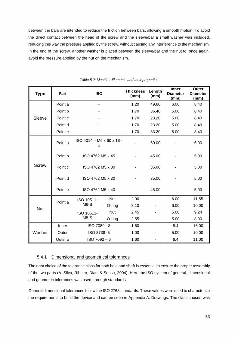
53
between the bars are intended to reduce the friction between bars, allowing a smooth motion. To avoid
the direct contact between the head of the screw and the sleeve/bar a small washer was included,
reducing this way the pressure applied by the screw, without causing any interference to the mechanism.
In the end of the screw, another washer is placed between the sleeve/bar and the nut to, once again,
avoid the pressure applied by the nut on the mechanism.
Table 5.2: Machine Elements and their properties
Type Part ISO Thickness
(mm) Length (mm)
Inner Diameter
(mm)
Outer Diameter
(mm)
Sleeve
Point a - 1.20 49.60 6.00 8.40
Point b - 1.70 36.40 5.00 8.40
Point c - 1.70 23.20 5.00 8.40
Point d - 1.70 23.20 5.00 8.40
Point e - 1.70 33.20 5.00 8.40
Screw
Point a ISO 4014 – M6 x 60 x 18 -
S - 60.00 - 6.00
Point b ISO 4762 M5 x 45 - 45.00 - 5.00
Point c ISO 4762 M5 x 30 - 35.00 - 5.00
Point d ISO 4762 M5 x 30 - 35.00 - 5.00
Point e ISO 4762 M5 x 40 - 45.00 - 5.00
Nut
Point a ISO 10511-
M6-S
Nut 2.90 - 6.00 11.55
O-ring 3.10 - 6.00 10.00
- ISO 10511-
M5-S
Nut 2.45 - 5.00 9.24
O-ring 2.55 - 5.00 8.00
Washer
Inner ISO 7089 - 8 1.60 - 8.4 16.00
Outer ISO 8738 -5 1.00 - 5.00 10.00
Outer a ISO 7092 – 6 1.60 - 6.4 11.00
5.4.1 Dimensional and geometrical tolerances
The right choice of the tolerance class for both hole and shaft is essential to ensure the proper assembly
of the two parts (A. Silva, Ribeiro, Dias, & Sousa, 2004). Here the ISO system of general, dimensional
and geometric tolerances was used, through standards.
General dimensional tolerances follow the ISO 2768 standards. These values were used to characterize
the requirements to build the device and can be seen in Appendix A: Drawings. The class chosen was
54
fine (f), because it is important to ensure that there are no gaps in the assembly that can hinder the
correct function of the mechanism.
Geometric tolerances concern two types of classes: quality class, represented by the letters IT and a
number, which is related to the function of the parts and to their fabrication process; and fundamental
deviation class, which is a non-functional tolerance that ensure the fits between two features of size
without constraints of orientation and location. This class is usually represented by a pair composed of
one letter and one number for each element. The letter symbolizes the fundamental deviation class and
the number states the production quality, i.e. the error magnitude (A. Silva et al., 2004). Both classes
follow the ISO 286-1 standard; there are 20 different quality classes and 28 fundamental deviation
classes.
In order to reduce the number of combinations between geometric classes, the recommended
adjustments are given by the ISO 1829 standard. For an easier selection of the right adjustment first a
set of tolerance classes is chosen, with the same fundamental deviation (the letter), and then the quality
class (IT) for the hole (the number). These classes are then combined with the recommended tolerance
class for the shaft element.
Taking in account that the device has general engineering/industry construction, the appropriate IT is
selected between 9 and 11. The recommend fit for a normal system hole is related to their application
and type of assemble. Since the assembly is intended to be done manually and the elements are axes,
screws and sleeves, the type of fits used can be free, rotary and tight rotary and the suggested classes
are H11-c11, H9-d9 and H8-f7 (A. Silva et al., 2004).
Knowing these requirements, and consulting the table of dimensional tolerance values for usual quality
classes, as seen in “Desenho Técnico Moderno” (A. Silva, C. T. Ribeiro, J. Dias, and L. Sousa, 2014, p
682) (A. Silva et al., 2004), the dimensional fits were chosen. IT 10 was the quality chosen to calculate
tolerances, since it was the best fit for the project.
These adjustments need to be made in every contact between two parts. This means not only the parts
that fit on each other, like the box in the support unit and the top of the box, but as well as between the
bars, the washers and the bearing brackets, and also the sleeve and every part linked by it.
In Table 5.3 the chosen tolerance values for the diverse parts are gathered. The value of adjustment is
usually calculated accordingly to the nominal diameter of the part that acts as a shaft. This part, or
element 1, is in direct contact with the second element, the hole, and must fit inside it.
The first two columns of Table 5.3 have the parts where these adjustments need to be made. In the third
column is the nominal dimension of the higher diameter of the shaft and in the last column is the
recommended tolerance for that value.
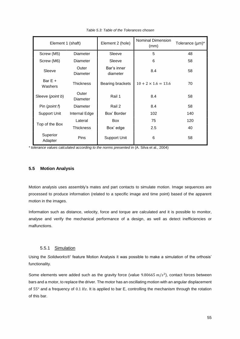
55
Table 5.3: Table of the Tolerances chosen
Element 1 (shaft) Element 2 (hole) Nominal Dimension
(mm) Tolerance (µm)*
Screw (M5) Diameter Sleeve 5 48
Screw (M6) Diameter Sleeve 6 58
Sleeve Outer
Diameter
Bar’s inner
diameter 8.4 58
Bar E +
Washers Thickness Bearing brackets 10 + 2 × 1.6 = 13.6 70
Sleeve (point b) Outer
Diameter Rail 1 8.4 58
Pin (point f) Diameter Rail 2 8.4 58
Support Unit Internal Edge Box’ Border 102 140
Top of the Box Lateral Box 75 120
Thickness Box’ edge 2.5 40
Superior
Adapter Pins Support Unit 6 58
* tolerance values calculated according to the norms presented in (A. Silva et al., 2004)
5.5 Motion Analysis
Motion analysis uses assembly’s mates and part contacts to simulate motion. Image sequences are
processed to produce information (related to a specific image and time point) based of the apparent
motion in the images.
Information such as distance, velocity, force and torque are calculated and it is possible to monitor,
analyse and verify the mechanical performance of a design, as well as detect inefficiencies or
malfunctions.
5.5.1 Simulation
Using the Solidworks®’ feature Motion Analysis it was possible to make a simulation of the orthosis’
functionality.
Some elements were added such as the gravity force (value 9.80665 𝑚/𝑠2), contact forces between
bars and a motor, to replace the driver. The motor has an oscillating motion with an angular displacement
of 55° and a frequency of 0.1 𝐻𝑧. It is applied to bar E, controlling the mechanism through the rotation
of this bar.

56
The simulation has duration of 5 seconds and starts with maximum dorsiflexion ending with maximum
plantarflexion, as depicted in Figure 5.3.
t = 0 t = 1 t = 2 t = 3 t = 4 t = 5
Figure 5.3: Frames of the simulation, from dorsiflexion (first) to plantar flexion (last), t (sec)
The first line of frames represent the simulation with the joint between the leg and the foot. In the second
line it is possible to see that although there is no connection between the upper and lower members the
biological axis of rotation of the foot is preserved, demonstrating the “jointless” effect.
Changing the frequency of the motor or increasing the duration of the simulation it is possible to obtain
more cycles of motion.
5.5.2 Relation between distance and angle
The motor is placed above bar E and connected to the support unit, so one end is point a (connection
of bars E, A and B) and the other end is on the attachment point for the motor on the support unit. It is
relevant to determine the variation of that distance to understand the behaviour of the spring in the
actuator.
On top of the support unit, another base was placed containing the bearing brackets where the motor is
connected. The simulation run without further changes and the linear displacement between point a and
the bearing brackets was measured in function of the angle that bar D make with the Z axis. The results
can be analysed in Figure 5.4.
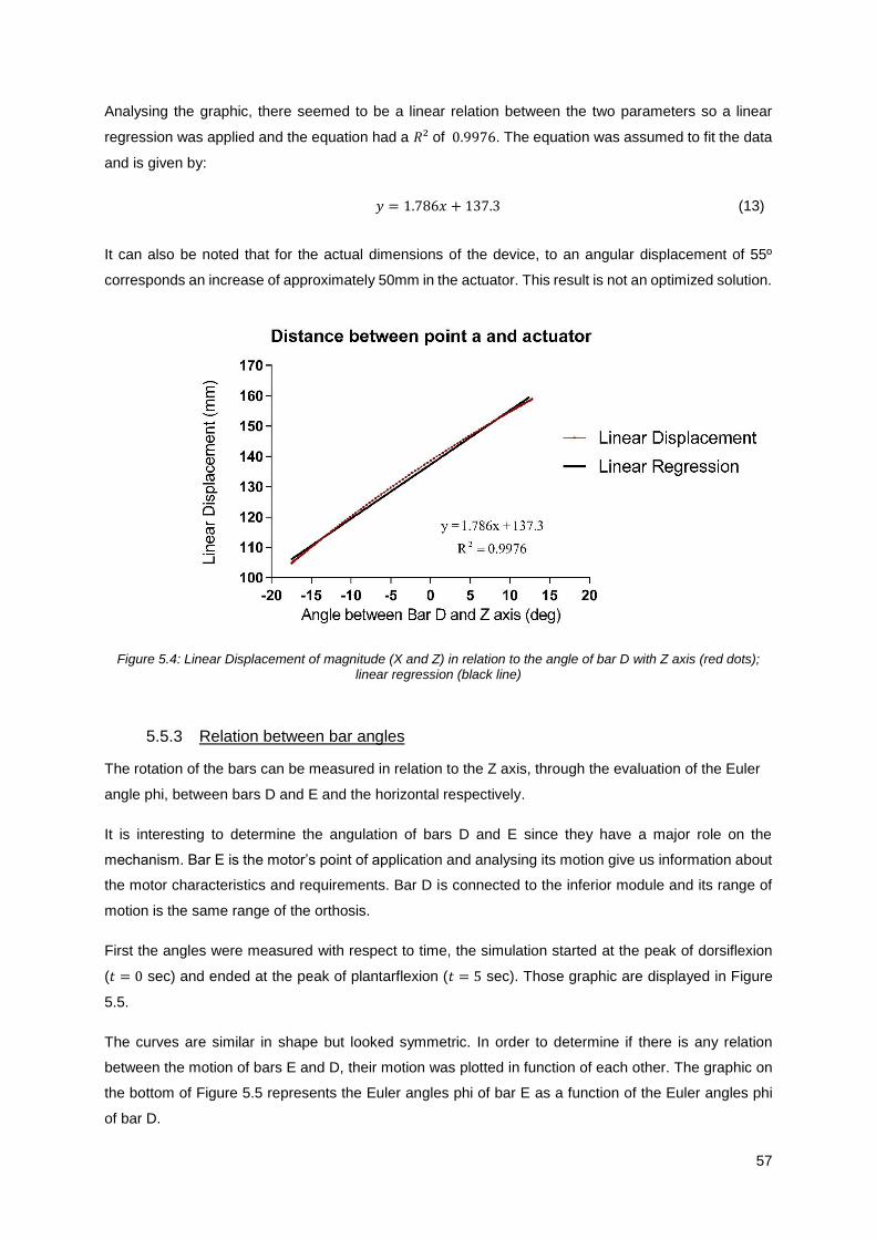
57
Analysing the graphic, there seemed to be a linear relation between the two parameters so a linear
regression was applied and the equation had a 𝑅² of 0.9976. The equation was assumed to fit the data
and is given by:
𝑦 = 1.786𝑥 + 137.3 (13)
It can also be noted that for the actual dimensions of the device, to an angular displacement of 55º
corresponds an increase of approximately 50mm in the actuator. This result is not an optimized solution.
Figure 5.4: Linear Displacement of magnitude (X and Z) in relation to the angle of bar D with Z axis (red dots); linear regression (black line)
5.5.3 Relation between bar angles
The rotation of the bars can be measured in relation to the Z axis, through the evaluation of the Euler
angle phi, between bars D and E and the horizontal respectively.
It is interesting to determine the angulation of bars D and E since they have a major role on the
mechanism. Bar E is the motor’s point of application and analysing its motion give us information about
the motor characteristics and requirements. Bar D is connected to the inferior module and its range of
motion is the same range of the orthosis.
First the angles were measured with respect to time, the simulation started at the peak of dorsiflexion
(𝑡 = 0 sec) and ended at the peak of plantarflexion (𝑡 = 5 sec). Those graphic are displayed in Figure
5.5.
The curves are similar in shape but looked symmetric. In order to determine if there is any relation
between the motion of bars E and D, their motion was plotted in function of each other. The graphic on
the bottom of Figure 5.5 represents the Euler angles phi of bar E as a function of the Euler angles phi
of bar D.

58
Figure 5.5: Up: Euler angles of Bar E (top) and Bar D (bottom); Down: relation between the angles
Analyzing the graphic the relation appeared to be linear. Applying a linear regression to the data there
was a high correlation with a 𝑅² = 0.9999; the curve can be characterized by:
𝑦 = −1.802𝑥 − 91.71 (14)
This means that for each degree changed in Bar D, Bar E rotates almost the double, 1.802 to be
accurate. The great advantage of this result is that since the motion of bar E is controlled by an actuator,
Bar E
Bar D
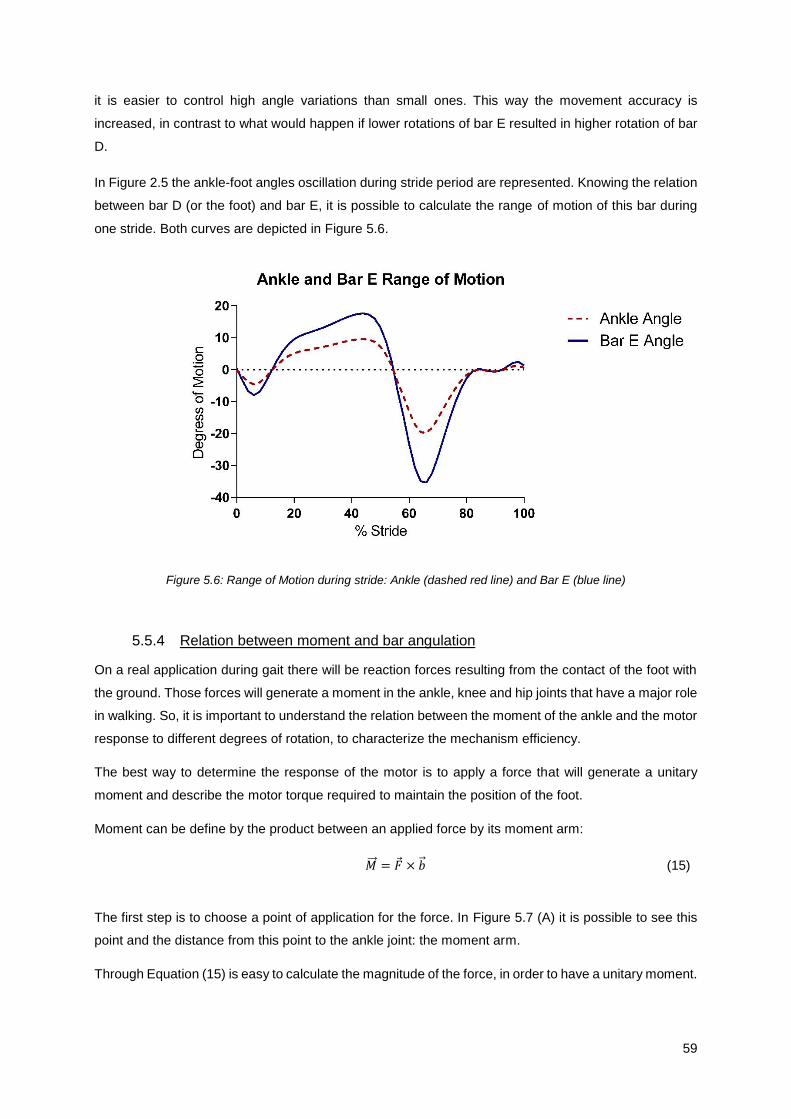
59
it is easier to control high angle variations than small ones. This way the movement accuracy is
increased, in contrast to what would happen if lower rotations of bar E resulted in higher rotation of bar
D.
In Figure 2.5 the ankle-foot angles oscillation during stride period are represented. Knowing the relation
between bar D (or the foot) and bar E, it is possible to calculate the range of motion of this bar during
one stride. Both curves are depicted in Figure 5.6.
Figure 5.6: Range of Motion during stride: Ankle (dashed red line) and Bar E (blue line)
5.5.4 Relation between moment and bar angulation
On a real application during gait there will be reaction forces resulting from the contact of the foot with
the ground. Those forces will generate a moment in the ankle, knee and hip joints that have a major role
in walking. So, it is important to understand the relation between the moment of the ankle and the motor
response to different degrees of rotation, to characterize the mechanism efficiency.
The best way to determine the response of the motor is to apply a force that will generate a unitary
moment and describe the motor torque required to maintain the position of the foot.
Moment can be define by the product between an applied force by its moment arm:
�⃗⃗⃗� = �⃗� × �⃗⃗� (15)
The first step is to choose a point of application for the force. In Figure 5.7 (A) it is possible to see this
point and the distance from this point to the ankle joint: the moment arm.
Through Equation (15) is easy to calculate the magnitude of the force, in order to have a unitary moment.

60
�⃗� =
𝑀
𝑏=
1 (𝑁. 𝑚)
140.05 × 10⁻³ (𝑚)= 7.14 𝑁
(16)
The force is always applied at the same point and perpendicular to the foot. In Figure 5.7 (B) the point
of application of the force and its direction (for the neutral position, peak of plantar flexion and peak of
dorsiflexion) is depicted.
Figure 5.7: A: moment arm; B: point of application and direction of the force for neutral position, plantar flexion and dorsiflexion
Some alterations were made to the simulation to change from a dynamic to a static evaluation. The
gravity force was removed and the time was no longer a key feature. The motor characteristics were
changed in order to sustain the initial configuration of the mechanism: the value for displacement was
reduced to zero, this way there would not be any variation of the position of bar E.
Changing the position of the foot for different values of angulation from plantar flexion to dorsiflexion
and calculating the motor torque for those values it is possible to see the response of the motor to a
unitary moment.
Moment and torque are similar concepts: moment is the tendency of a distant force to rotate an object
and torque is the rotational force applied to the axis of rotation driving the rotation; moment is a static
force, so it is used when there is no rotation and torque a movement force, used when there is rotation
and a pivot.
In Figure 5.8 is displayed the graphic with that relation.
A
B
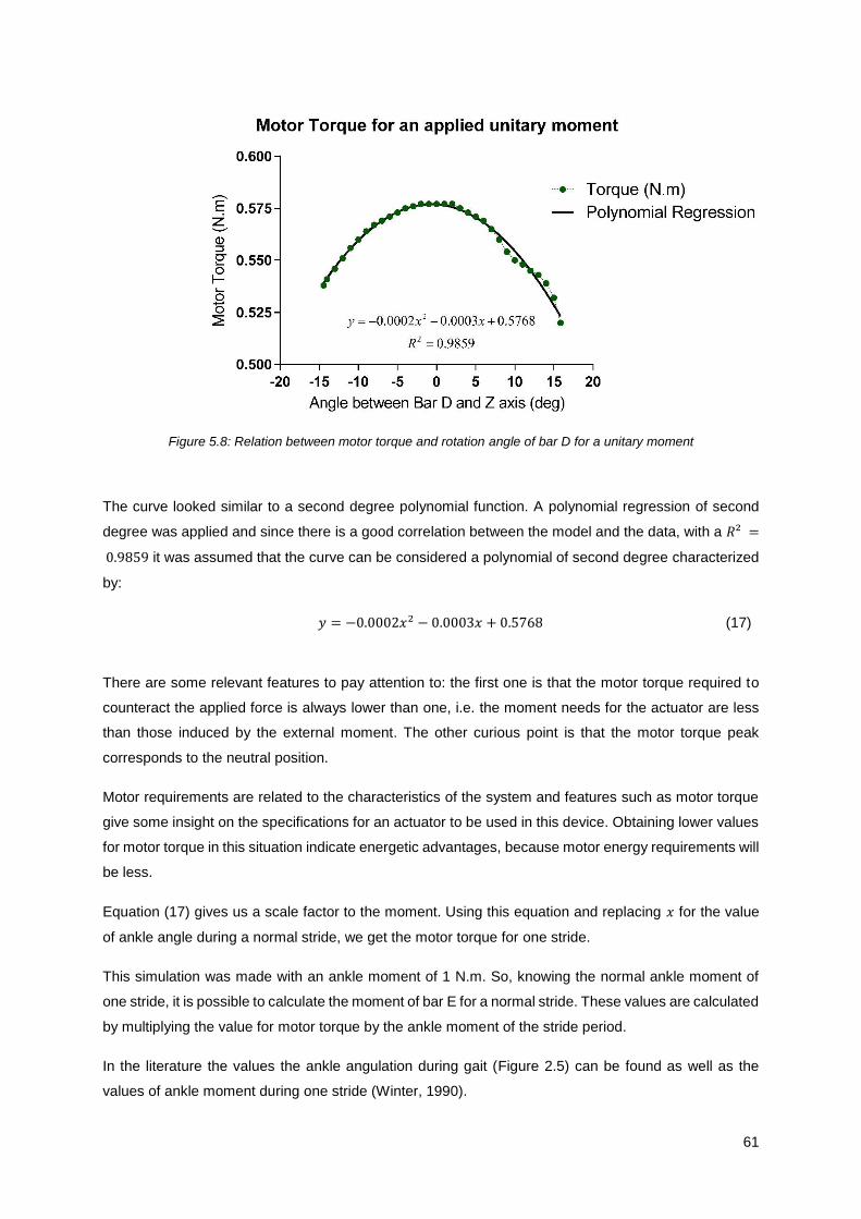
61
Figure 5.8: Relation between motor torque and rotation angle of bar D for a unitary moment
The curve looked similar to a second degree polynomial function. A polynomial regression of second
degree was applied and since there is a good correlation between the model and the data, with a 𝑅² =
0.9859 it was assumed that the curve can be considered a polynomial of second degree characterized
by:
𝑦 = −0.0002𝑥2 − 0.0003𝑥 + 0.5768 (17)
There are some relevant features to pay attention to: the first one is that the motor torque required to
counteract the applied force is always lower than one, i.e. the moment needs for the actuator are less
than those induced by the external moment. The other curious point is that the motor torque peak
corresponds to the neutral position.
Motor requirements are related to the characteristics of the system and features such as motor torque
give some insight on the specifications for an actuator to be used in this device. Obtaining lower values
for motor torque in this situation indicate energetic advantages, because motor energy requirements will
be less.
Equation (17) gives us a scale factor to the moment. Using this equation and replacing 𝑥 for the value
of ankle angle during a normal stride, we get the motor torque for one stride.
This simulation was made with an ankle moment of 1 N.m. So, knowing the normal ankle moment of
one stride, it is possible to calculate the moment of bar E for a normal stride. These values are calculated
by multiplying the value for motor torque by the ankle moment of the stride period.
In the literature the values the ankle angulation during gait (Figure 2.5) can be found as well as the
values of ankle moment during one stride (Winter, 1990).
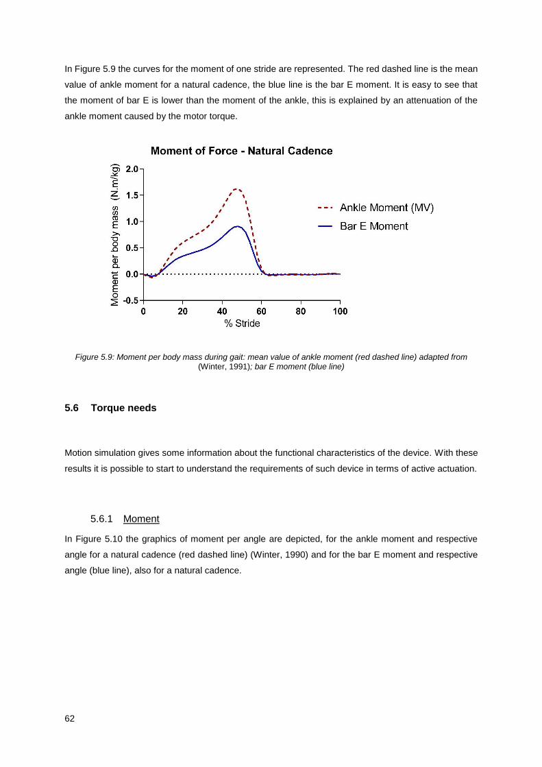
62
In Figure 5.9 the curves for the moment of one stride are represented. The red dashed line is the mean
value of ankle moment for a natural cadence, the blue line is the bar E moment. It is easy to see that
the moment of bar E is lower than the moment of the ankle, this is explained by an attenuation of the
ankle moment caused by the motor torque.
Figure 5.9: Moment per body mass during gait: mean value of ankle moment (red dashed line) adapted from (Winter, 1991); bar E moment (blue line)
5.6 Torque needs
Motion simulation gives some information about the functional characteristics of the device. With these
results it is possible to start to understand the requirements of such device in terms of active actuation.
5.6.1 Moment
In Figure 5.10 the graphics of moment per angle are depicted, for the ankle moment and respective
angle for a natural cadence (red dashed line) (Winter, 1990) and for the bar E moment and respective
angle (blue line), also for a natural cadence.
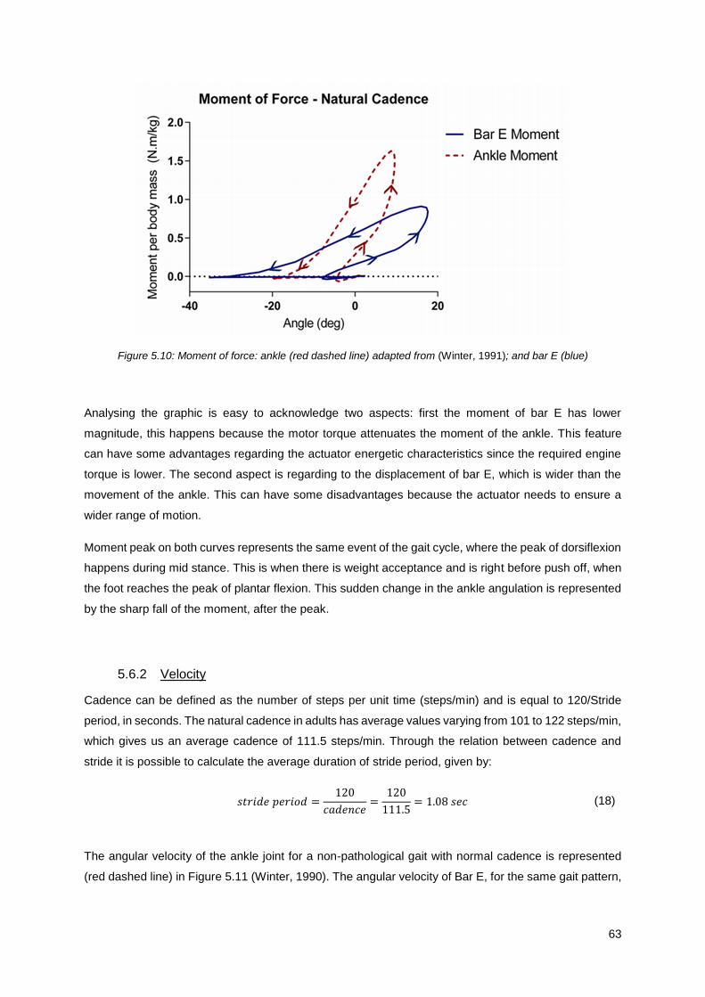
63
Figure 5.10: Moment of force: ankle (red dashed line) adapted from (Winter, 1991); and bar E (blue)
Analysing the graphic is easy to acknowledge two aspects: first the moment of bar E has lower
magnitude, this happens because the motor torque attenuates the moment of the ankle. This feature
can have some advantages regarding the actuator energetic characteristics since the required engine
torque is lower. The second aspect is regarding to the displacement of bar E, which is wider than the
movement of the ankle. This can have some disadvantages because the actuator needs to ensure a
wider range of motion.
Moment peak on both curves represents the same event of the gait cycle, where the peak of dorsiflexion
happens during mid stance. This is when there is weight acceptance and is right before push off, when
the foot reaches the peak of plantar flexion. This sudden change in the ankle angulation is represented
by the sharp fall of the moment, after the peak.
5.6.2 Velocity
Cadence can be defined as the number of steps per unit time (steps/min) and is equal to 120/Stride
period, in seconds. The natural cadence in adults has average values varying from 101 to 122 steps/min,
which gives us an average cadence of 111.5 steps/min. Through the relation between cadence and
stride it is possible to calculate the average duration of stride period, given by:
𝑠𝑡𝑟𝑖𝑑𝑒 𝑝𝑒𝑟𝑖𝑜𝑑 =120
𝑐𝑎𝑑𝑒𝑛𝑐𝑒=
120
111.5= 1.08 𝑠𝑒𝑐 (18)
The angular velocity of the ankle joint for a non-pathological gait with normal cadence is represented
(red dashed line) in Figure 5.11 (Winter, 1990). The angular velocity of Bar E, for the same gait pattern,

64
is also depicted in Figure 5.11 (blue line) and was calculated through the finite difference method,
applied to the angle variation of Bar E during gait, determined in chapter 5.5.3.
The finite difference method is a numerical method to approximate the derivative of a function, and can
be defined by:
𝑓′(𝑎) =𝑓(𝑎 + ℎ) − 𝑓(𝑎)
ℎ (19)
In this case, 𝑓′(𝑎) is the angular velocity, 𝑓(𝑎) the angle distribution during one stride and ℎ is the time
step. The time step can be calculated by dividing the duration of the stride period (in seconds) by the
number of points less one (because with this method one point is lost). So, the time step is:
ℎ =1.08
50 − 1= 0.02 𝑠𝑒𝑐 (20)
The next step was to convert the velocity to rad/sec, by multiplying the data by 𝜋
180.
Figure 5.11: Angular velocity: ankle (red dashed line) adapted from (Winter, 1991); and bar E (blue line)
Analysing the graphic there is a high similarity between the curves, where the velocity of bar E has
higher values, as expected, since there is a greater movement amplitude in this bar, for the same stage
of the stride period.
The higher values of velocity appear on both curves for the same stage of stride: the first peak is during
the stance phase, when the foot is at maximum plantarflexion and happens the phase of weight
acceptance. The next peak happens in the end of stance phase, during push off, which is the stage with
more energy expenditure. Between this peak and the last one there is a sudden increasing of velocity
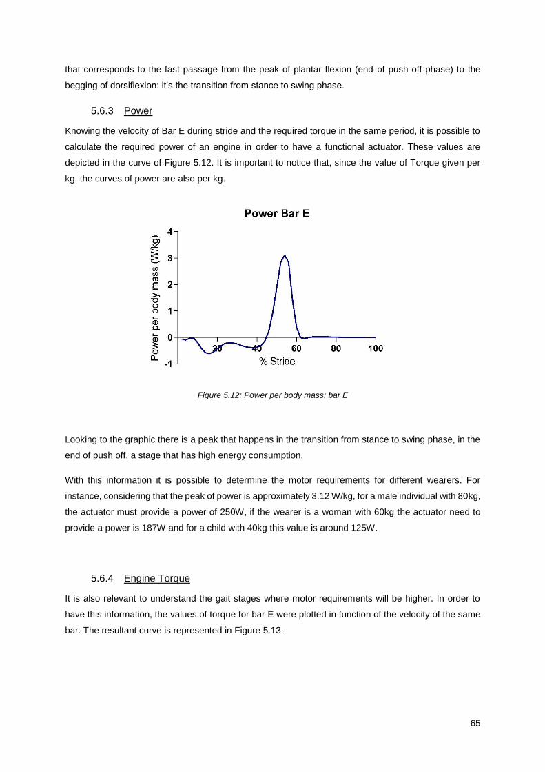
65
that corresponds to the fast passage from the peak of plantar flexion (end of push off phase) to the
begging of dorsiflexion: it’s the transition from stance to swing phase.
5.6.3 Power
Knowing the velocity of Bar E during stride and the required torque in the same period, it is possible to
calculate the required power of an engine in order to have a functional actuator. These values are
depicted in the curve of Figure 5.12. It is important to notice that, since the value of Torque given per
kg, the curves of power are also per kg.
Figure 5.12: Power per body mass: bar E
Looking to the graphic there is a peak that happens in the transition from stance to swing phase, in the
end of push off, a stage that has high energy consumption.
With this information it is possible to determine the motor requirements for different wearers. For
instance, considering that the peak of power is approximately 3.12 W/kg, for a male individual with 80kg,
the actuator must provide a power of 250W, if the wearer is a woman with 60kg the actuator need to
provide a power is 187W and for a child with 40kg this value is around 125W.
5.6.4 Engine Torque
It is also relevant to understand the gait stages where motor requirements will be higher. In order to
have this information, the values of torque for bar E were plotted in function of the velocity of the same
bar. The resultant curve is represented in Figure 5.13.
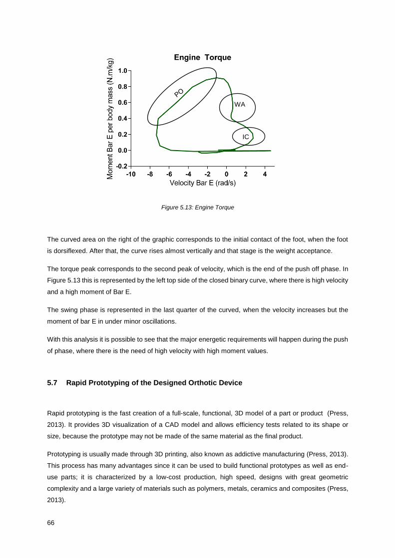
66
Figure 5.13: Engine Torque
The curved area on the right of the graphic corresponds to the initial contact of the foot, when the foot
is dorsiflexed. After that, the curve rises almost vertically and that stage is the weight acceptance.
The torque peak corresponds to the second peak of velocity, which is the end of the push off phase. In
Figure 5.13 this is represented by the left top side of the closed binary curve, where there is high velocity
and a high moment of Bar E.
The swing phase is represented in the last quarter of the curved, when the velocity increases but the
moment of bar E in under minor oscillations.
With this analysis it is possible to see that the major energetic requirements will happen during the push
of phase, where there is the need of high velocity with high moment values.
5.7 Rapid Prototyping of the Designed Orthotic Device
Rapid prototyping is the fast creation of a full-scale, functional, 3D model of a part or product (Press,
2013). It provides 3D visualization of a CAD model and allows efficiency tests related to its shape or
size, because the prototype may not be made of the same material as the final product.
Prototyping is usually made through 3D printing, also known as addictive manufacturing (Press, 2013).
This process has many advantages since it can be used to build functional prototypes as well as end-
use parts; it is characterized by a low-cost production, high speed, designs with great geometric
complexity and a large variety of materials such as polymers, metals, ceramics and composites (Press,
2013).
WA
IC
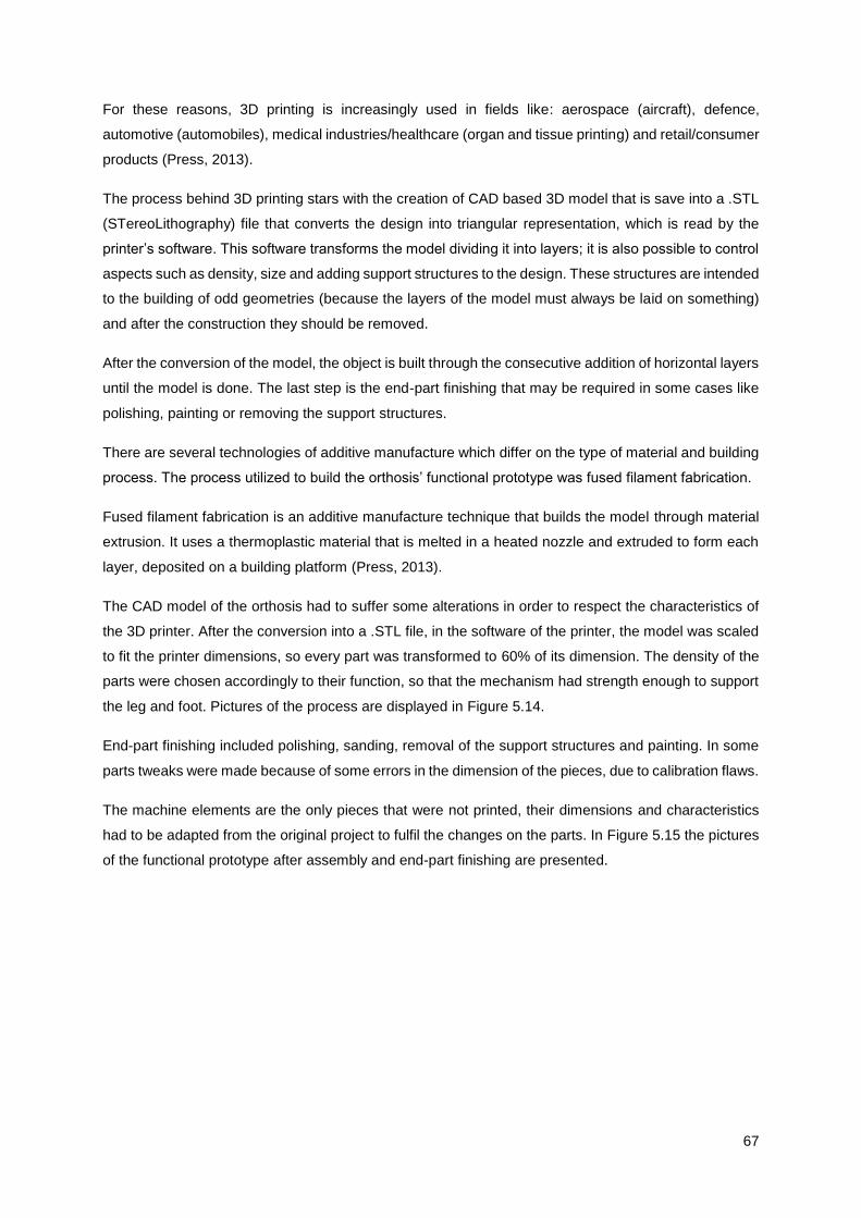
67
For these reasons, 3D printing is increasingly used in fields like: aerospace (aircraft), defence,
automotive (automobiles), medical industries/healthcare (organ and tissue printing) and retail/consumer
products (Press, 2013).
The process behind 3D printing stars with the creation of CAD based 3D model that is save into a .STL
(STereoLithography) file that converts the design into triangular representation, which is read by the
printer’s software. This software transforms the model dividing it into layers; it is also possible to control
aspects such as density, size and adding support structures to the design. These structures are intended
to the building of odd geometries (because the layers of the model must always be laid on something)
and after the construction they should be removed.
After the conversion of the model, the object is built through the consecutive addition of horizontal layers
until the model is done. The last step is the end-part finishing that may be required in some cases like
polishing, painting or removing the support structures.
There are several technologies of additive manufacture which differ on the type of material and building
process. The process utilized to build the orthosis’ functional prototype was fused filament fabrication.
Fused filament fabrication is an additive manufacture technique that builds the model through material
extrusion. It uses a thermoplastic material that is melted in a heated nozzle and extruded to form each
layer, deposited on a building platform (Press, 2013).
The CAD model of the orthosis had to suffer some alterations in order to respect the characteristics of
the 3D printer. After the conversion into a .STL file, in the software of the printer, the model was scaled
to fit the printer dimensions, so every part was transformed to 60% of its dimension. The density of the
parts were chosen accordingly to their function, so that the mechanism had strength enough to support
the leg and foot. Pictures of the process are displayed in Figure 5.14.
End-part finishing included polishing, sanding, removal of the support structures and painting. In some
parts tweaks were made because of some errors in the dimension of the pieces, due to calibration flaws.
The machine elements are the only pieces that were not printed, their dimensions and characteristics
had to be adapted from the original project to fulfil the changes on the parts. In Figure 5.15 the pictures
of the functional prototype after assembly and end-part finishing are presented.
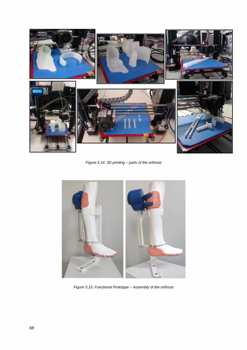
68
Figure 5.14: 3D printing – parts of the orthosis
Figure 5.15: Functional Prototype – Assembly of the orthosis
69
Chapter 6
6.
Conclusions and Future Work
6.1 Conclusions
In this work a novel Ankle-Foot Orthosis (AFO) was developed for locomotion support and assistance.
In the development of the new concept of AFO some aspects were taking in consideration such as its
modular concept and the exterior joint that created the “jointless” effect. In order to exploit this notions
there was a detailed study of the basic topics of this subject, related to the physiology of the foot,
characteristics of orthoses and the new mechanism.
The development of the new concept was described since the first sketch to the final product. Two main
goals needed to be achieved: the creation of a modular device and the shift of the joint location to the
back of the leg.
The modular solution is based on the mechanism responsible for the motion of the orthosis that is a
combination of a four-bar linkage with a two-rail system. Through the analysis of the degrees of freedom
of the mechanism it was ensured that it had only one degree of freedom, the one allowing dorsiflexion
and plantar flexion of the foot. The rails were design to allow a range of motion of 30° and the device
should be aligned with the anatomical deviation of the ankle joint’ axis.
Another relevant feature is the duality of the device that can act as an articulated or non-articulated
orthosis, depending on the type of mechanical element used and as a passive or active orthosis,
depending on the type of actuation. In the passive solution the orthosis is built to function with springs
or elastic bands that should be chosen accordingly to the wearers needs, because each element plays
a different role. For instance, the non-articulated configuration can be achieved if an elastic band with
high stiffness is chosen; on the other hand, choosing a spring it’s possible to have a device which
promotes dorsiflexion and controlled plantarflexion, preventing drop foot gait. In the active solution the
device is designed to include an actuator to actively assist gait. The ideal actuator would work with a
spring with variable impedance to allow a better adjustment to the distinct phases of gait and to different
patients. The study and development of this type of actuator should be addressed in the future.
The three-module orthosis is comprised of the mechanism module, described above, and two adaptable
units: the superior and inferior modules. These two features are patient specific and are built for each

70
wearer by the orthotist. The modular orthosis is adapted to these parts which eases the fabrication
process of these devices. This solutions incorporates all the components of an active solutions, such
as, an actuator, control system and sensors; so there is no need of adding extra elements to have an
active solution. That allows for commercial solutions for active orthotics to appear in the market.
The parts of the mechanism were described in detail and a simple model of the actuator is presented
for dimensional reference. The mechanical details such as the machine elements and the values for the
tolerances were discussed. These peculiarities reveal to be very important during the assembly of the
3D prototype.
Motion analysis was made considering the motion from the peak of dorsiflexion until the peak of plantar
flexion. This analysis intend to a better understand of some features of the device and to allow a
preliminary characterization of the motor requirements. Three aspects were studied with special
attention: the relation between the angulation of bar D with the Z axis and the distance between point a
and the support of the actuator; and the angulation of bar E with the Z axis and the motor torque for a
unitary moment applied in the inferior module.
From the results obtained it is important to notice that: first there is a linear relation between the length
of the actuator and the rotation of the foot; second, the rotation of bar E is bigger than that of bar D,
increasing the precision of the foot motion and third, the mechanism acts as a torque amplifier since the
moment necessary to counteract the external applied one is less than the latter and, consequently, the
demand of actuator’s motor torque is smaller.
Through this analysis it was possible to characterize the requirements of an actuator for this device.
Using the relation between bars’ angles, the equation for motor torque for a unitary moment and some
values regarding a normal cadence of non-pathological gait, it was possible to determine a few motor
characteristics.
Comparing ankle moment during one stride with the correspondent moment of bar E, it was possible to
conclude that the last one had lower magnitude but with a wider range of motion. In terms of velocities,
as expected, bar E required more velocity since there is a wider range of motion during gait; the peak
of velocity happens in the transition from stance to swing phase because the foot goes from peak of
plantar flexion (end of push off phase) to the begging of dorsiflexion in a short period of time.
Calculating the power required to move bar E, the peak of power, once again, corresponds to the
transition from stance to swing phase. The engine torque for bar E was also analysed and it was possible
to conclude that the stage of the gait cycle where there was the higher requirements for both velocity
and moment was during push off.
The creation and assembly of a 3D functional prototype, through addictive fabrication, is also described.
Having the possibility to produce a prototype is of extreme relevance for every research work. The
prototype allowed an in-depth understanding of the device and its operation. It enhance the importance
71
of tolerance values and the dimensions of the machine elements, key factors to the good performance
of the device.
There are three fundamental principles that must be addressed when considering a novel concept:
functionality, applicability and usability.
The novel concept of orthosis is functional and fulfils its requirements: it’s a modular device, with an
exterior set of joints that replace the inside joint, usually placed near the anatomical joint. It only has one
degree of freedom that allows the motion on the foot only in axis responsible for dorsiflexion and
plantarflexion rotations.
It can be applied to assist different pathologies and patients with different degrees of gait impairments.
The AFO’s design characteristics allow building devices with distinct configurations, adapted to each
situation. This way the same concept can be adjusted to someone who needs support during the swing
phase of the gait cycle, to assist dorsiflexion or to someone who due to lack of muscle action needs an
active device to assist both plantar flexion and dorsiflexion.
As result of the characteristics mention above, this device has three working environments:
rehabilitation/physical therapy facilities, in which it accelerates the rehabilitation process by working
together with the physiotherapist; home recovery, as it assists simple activities such as walking and
giving more support and security to the wearer; and daily use, as it improves the quality of life of people
with gait impairments by correcting and/or assisting their gait.
When thinking about orthotic and prosthetic devices, it is important to acknowledge the big difference
between them. While with prosthetic devices the main objective is to replace a biological structure by
an artificial ones, in orthotic devices the disable limb that must work in parallel with the device. So every
orthoses design must respect the normal performance of the limb and reduce to a minimum the
interference that the device can cause to the limb. That’s why it is so important to decrease the patient
dependent parts in a device and reduce the contact areas with the wearer.
Orthosis are always fighting against the host. The perfect balance is achieved when the wearer fully
accept the device and together they work to counterbalance impairments.
6.2 Future Work
A long path needs to be pursued until the device is ready to be commercialized and used by individuals
with gait disorders.
The areas for futures work fall into five main categories: AFO design, biomechanical details, dimensional
generalization, structural analysis, and application outcomes.
The AFO design is detailed in Chapters 4 and 5; there are some aspects that can be improved. At this
stage, the design of the orthosis prevents the individual from wearing pants and this can be a key factor
72
from transforming this device into an everyday wearable solution. Therefore, some changes to the
design should be made to transform the device into a more compact model. To achieve this solution,
the dimension of the bars should be corrected, using Freudenstein’s equations and an optimization
process. This way, the modular solution would be thinner and more attractive to the wearer.
According to biomechanical principles, the axis of rotation of the device should be perfectly aligned with
the rotation axis of the member. In this regard, to correct the deviation of the ankle joint axis, research
should be made to replace one of the revolution joints of the mechanism for a spherical joint in order to
allow a better axis alignment. Along with that, research could be made to increase the number of DOF
of the device, in order to englobe other foot movements such as inversion and eversion.
With this work there was the development of a proof-of-concept and the functional analysis of the device.
Although the relation between the bar dimensions and their angulation is known, there should be made
a study to understand if the shape of the rails suffer any change with the adaptation of the bars to
different leg sizes. Only then there will be sufficient information to fully generalize the device.
After a preliminary analysis, there is no trivial relation between the shape of the rails and the dimension
of the four bar mechanism. This implies that before the adaptation to different heights there should be
an intermediate step to adjust the model.
To understand which material should be chosen to fabricate the orthosis, a structural analysis should
be made. Using Finite Element Analysis it is possible to identify the areas that have higher stresses and
adjust structural design to avoid failure. Applying a mechanical test procedure to the device it is possible
to know the forces acting in each bar, which will allow the proper adjustments and sizing of the
mechanism.
Once the final design is accomplish, with the right material and the best configuration, it is of extreme
relevance to apply the AFO to different case studies and study the effect of wearing the AFO. It is
important to understand if the patient feels any discomfort or if the orthosis is acting against the normal
movement of the foot so that it can be corrected. Only after this careful analysis of the use of the device
and its effects, the orthosis is ready to be available as a product.
73
References
Alam, M., Choudhury, I. A., & Mamat, A. Bin. (2014). Mechanism and Design Analysis of Articulated
Ankle Foot Orthoses for Drop-Foot. TheScientificWorldJournal, 2014, 867869.
http://doi.org/10.1155/2014/867869
Alves da Silva, J. R. (2014). Avaliação e Certificação de dispositivos Protéticos e Ortéticos para o
Membro Inferior. Master Thesis, Biomedical Engeneering, Universidade do Porto.
ArizonaAFO. (2015). Articulated AFO. Retrieved from
http://www.arizonaafo.com/default/index.cfm/side-bar/product-line/articulated-afo/
Beer, F. P., E. Russell Johnston, J., Dewolf, J. T., & Mazurek, D. F. (2012). Mechanics of Materials, 9–
15; 54–69; 113–116.
Berkelman, P., Rossi, P., Lu, T., & Ma, J. (2007). Passive orthosis linkage for locomotor rehabilitation.
2007 IEEE 10th International Conference on Rehabilitation Robotics, ICORR’07, 00(c), 425–431.
http://doi.org/10.1109/ICORR.2007.4428460
Blaya, J. a., & Herr, H. (2004). Adaptive Control of a Variable-Impedance Ankle-Foot Orthosis to Assist
Drop-Foot Gait. IEEE Transactions on Neural Systems and Rehabilitation Engineering, 12(1), 24–
31. http://doi.org/10.1109/TNSRE.2003.823266
Cenciarini, M., & Dollar, A. M. (2011). Biomechanical considerations in the design of lower limb
exoskeletons. IEEE International Conference on Rehabilitation Robotics, 10–14.
http://doi.org/10.1109/ICORR.2011.5975366
Chern, J. S., Chang, H. S., Lung, C. W., Wu, C. Y., & Tang, S. F. (2013). Static ankle-foot orthosis
improves static balance and gait functions in hemiplegic patients after stroke. Proceedings of the
Annual International Conference of the IEEE Engineering in Medicine and Biology Society, EMBS,
5009–5012. http://doi.org/10.1109/EMBC.2013.6610673
Cobb, G. L. (1935). Walking motion.
c-prodirect. (2015). Single ADM attached to a day shoe. Retrieved from http://www.c-
prodirect.co.uk/adm/single-adm-attached-to-a-day-shoe.html
DGS. (2014). Portugal: Doenças Cérebro-Cardiovasculares em números - 2014. Retrieved from
http://www.dgs.pt
Díaz, I., Gil, J. J., & Sánchez, E. (2011). Lower-Limb Robotic Rehabilitation: Literature Review and
Challenges. Journal of Robotics, 2011(i), 1–11. http://doi.org/10.1155/2011/759764
Dollar, A., & Herr, H. (2008). Lower Extremity Exoskeletons and Active Orthoses:Challenges and State-
of-the-Art, 24(1), 144–158.
Dubin, A. (2014). Gait. The role of the ankle and foot in walking. Medical Clinics of North America, 98(2),
205–211. http://doi.org/10.1016/j.mcna.2013.10.002
Engineering.com. (2006). Retrieved January 1, 2015, from
http://files.engineering.com/getfile.aspx?folder=e7326b6a-5314-45d1-a8a8-
b774999e011f&file=Jack-solid.x_t
Faustini, M. C., Neptune, R. R., Crawford, R. H., & Stanhope, S. J. (2008). Manufacture of Passive
Dynamic Ankle-Foot Orthoses Using Selective Laser Sintering. IEEE Transactions on Biomedical
Engineering, 55(2), 784–790. http://doi.org/10.1109/TBME.2007.912638
Filippi, P. (1942). Device for the automatic control of the articulation of the knee applicable to a
prosthesis of the thigh. Retrieved from http://ci.nii.ac.jp/naid/40006880825/

74
Fillauer. (2015). Dynamic Walk from Centri. Retrieved from http://fillauer.com/pdf/AD290-Dynamic-
Walk.pdf
Fish, D. J. (1997). Characteristic Gait Patterns in Neuromuscular Patholoies. JPO: Journal of Prosthetics
and Orthotics, 9, 163–167.
Freudenstein, F. (1955). Approximate synthesis of four-bar linkages. ASME Trans., 77(8), 853–861.
http://doi.org/10.1007/s12045-010-0084-7
Ghosal, A. (2002). The Freudenstein Equation and Design of Four-link Mechanisms, 1–9.
Gordon, K. E., Sawicki, G. S., & Ferris, D. P. (2006). Mechanical performance of artificial pneumatic
muscles to power an ankle-foot orthosis. Journal of Biomechanics, 39(10), 1832–1841.
http://doi.org/10.1016/j.jbiomech.2005.05.018
Hall, S. J. (2011). Basic Biomechanics (Sixth). McGraw-Hill.
Harper, N. G., Esposito, E. R., Wilken, J. M., & Neptune, R. R. (2014). The Influence of Ankle-Foot
Orthosis Stiffness on Walking Performance in Individuals with Lower Limb Impairments. Clinical
Biomechanics, 29, 877–884. http://doi.org/10.1016/j.clinbiomech.2014.07.005
Herr, H. (2009). Exoskeletons and orthoses: classification, design challenges and future directions.
Journal of Neuroengineering and Rehabilitation, 6, 21. http://doi.org/10.1186/1743-0003-6-21
Hertel, J. (2002). Functional anatomy, pathomechanics, and pathophysiology of lateral ankle instability.
Journal of Athletic Training, 37(4), 364–375.
Hollander, K. W., Sugar, T. G., & Herring, D. E. (2005). Adjustable Robotic Tendon Using a “Jack
Spring.” Proceedings of the 2005 IEEE 9th International Conference on Rehabilitation Robotics,
2005, 113–118. http://doi.org/10.1109/ICORR.2005.1501064
INE. (2011). Censos 2011: resultados provisórios - Portugal.
Infarmed. (2009). infarmed: Autoridade Nacional do Medicamento e Produtos de Saúde I.P. Retrieved
October 23, 2015, from http://www.infarmed.pt/portal/page/portal/INFARMED
Jankovic, J. (2015). Gait Disorders. Neurologic Clinics, 33(1), 249–268.
http://doi.org/10.1016/j.ncl.2014.09.007
Kaufman, K. R., & Irby, S. E. (2006). Ambulatory KAFOs: A Biomechanical Engineering Perspective.
JPO Journal of Prosthetics and Orthotics, 18(Proceedings), P175–P182.
http://doi.org/10.1097/00008526-200606001-00005
Melo, P. L., Vasconcelos, C. F., Martins, J. M., & Silva, M. T. (2011). Desenvolvimento de uma Ortótese
Tornozelo-Pé com Actuação Hibria para Apoio à Locomoção. In 4o Congresso Nacional de
Biomecânica (pp. 645–650). Coimbra.
Michaud, T. C. (2011). Human Locomotion: The Conservative Management of Gait-related Disorders.
Newton Biomechanics.
Milusheva, S., Tosheva, E., Tochev, D., & Toshev, Y. (2007). Ankle Foot Orthosis With Exchangeable
Elastic Elements. Journal of Biomechanics, 40(1), S592. http://doi.org/10.1016/S0021-
9290(07)70580-8
Mori, M. (1970). The Uncanny Valley. IEEE ROBOTICS & AUTOMATION MAGAZINE, 7(4), 33–35.
Murphy, J. H. (1951). Leg Brace. USA.
OrthoBaltic. (2015). Easy Walk AFO-10E eco. Retrieved from
http://www.orthobaltic.eu/application/images/File/AFO-10E_N.pdf
75
ÖSSUR. (2015). Lower Extremity Braces & Supports. Retrieved from
http://assets.ossur.com/library/15900/OrthoCatalog09 33.pdf
Ottobock. (2015). The new Unilateral Joint System. Modular and multifuncional. Retrieved from
http://www.ottobock.com/cps/rde/xbcr/ob_com_en/646D789-EN-02-1404w.pdf
Palastanga, N., & Soames, R. (2012). Anatomy and human movement: structure and function. (R.
Demetriou-Swanwick & S. Davies, Eds.) (Sixth). Elsevier Ltd. Retrieved from
http://scholar.google.com/scholar?hl=en&btnG=Search&q=intitle:Anatomy+and+Human+Movem
ent:+Structure+and+Function#0\nhttp://scholar.google.com/scholar?hl=en&btnG=Search&q=intitl
e:Anatomy+and+human+movement:+structure+and+function#0
Perry, J. (1992). Gait Analysis: Normal and Pathological Function. Book by SLACKIncorporated. Grove
Road: SLACK Incorporated.
PORDATA: Base de Dados Portugal Contemporâneo. (2011). Retrieved October 18, 2015, from
http://www.pordata.pt/Home
Prentice, W. E., & Voight, M. L. (2001). Techniques in Musculoskeletal Rehabilitation (First edit).
McGraw-Hill Medical.
Press, D. U. (2013). The 3D opportunity primer: the basics of additive manufacturing, 1–20.
Roaas, A., & Andersson, G. B. (1982). Normal range of motion of the hip, knee and ankle joints in male
subjects, 30-40 years of age. Acta Orthopaedica Scandinavica, 53(2), 205–208.
Rodrigues, I. O. (2012). Ortodesign: Redesing de Ortótese para Paralesia do Nervo Radial. Master
Thesis, Faculdade de Belas Artes, Universidade de Lisboa.
Saunders, J. B., Inman, V. T., & Eberhart, H. D. (1953). The major determinants in normal and
pathological gait. The Journal of Bone and Joint Surgery. American Volume, 35-A(3), 543–558.
http://doi.org/10.1007/978-1-4471-5451-8_102
Schrank, E. S., & Stanhope, S. J. (2011). Dimensional accuracy of ankle-foot orthoses constructed by
rapid customization and manufacturing framework. Journal of Rehabilitation Research and
Development, 48(1), 31–42. http://doi.org/10.1682/JRRD.2009.12.0195
Seymour, R. (2002). Prosthetics and Orthotics: Lower Limb and Spinal. (T. Julet, U. Lushnycky, N.
Peterson, & J. Ajello, Eds.). Syracuse, New York: Lippincottt Williams & Wilkins.
Shorter, K. A., Kogler, G. F., Loth, E., Durfee, W. K., & Hsiao-Wecksler, E. T. (2011). A portable powered
ankle-foot orthosis for rehabilitation. Journal of Rehabilitation Research and Development, 48(4),
459–472. http://doi.org/10.1682/JRRD.2010.04.0054
Shorter, K. A., Xia, J., Hsiao-Wecksler, E. T., Durfee, W. K., & Kogler, G. F. (2013). Technologies for
powered ankle-foot orthotic systems: Possibilities and challenges. IEEE/ASME Transactions on
Mechatronics, 18(1), 337–347. http://doi.org/10.1109/TMECH.2011.2174799
Silva, A., Ribeiro, C. T., Dias, J., & Sousa, L. (2004). Desenho Técnico Moderno. (G. LIDEL, Ed.) (4a
Edição). Lisboa.
Silva, P. C., Silva, M. T., & Martins, J. M. (2010). Evaluation of the contact forces developed in the lower
limb/orthosis interface for comfort design. Multibody System Dynamics, 24(3), 367–388.
http://doi.org/10.1007/s11044-010-9219-6
Stevens, C. M. (1906). Ankle-Brace. United States, West Virginia.
Sugar, T., & Hollander, K. (2011). Adjustable Stifness Jack Spring Actuator. Washington, DC.
76
Todorov, T. S. (2015). Synthesis of Four Bar Mechanisms as Function Generators by Freudenstein -
Chebyshev. Journal of Robotics and Mechanical Engineering Research, 1(1), 1–6.
Tranmer, F. (1920). Ankle-Brace and Arch-Support. United States, Nebraska.
Trulife. (2015). AFO. Retrieved from http://trulife.com/Brochures/afo-section-new-cat.pdf
Vasconcelos, C. F., Melo, P. L., Martins, J. M., & Silva, M. T. (2013). Control of a Froce Sensing Actuator
to Assist the Ankle Joint Movement. In 5th Portuguese Congress on Biomechanics (pp. 3–7).
Espinho.
Vistamehr, A., Kautz, S. a., & Neptune, R. R. (2014). The influence of solid ankle-foot-orthoses on
forward propulsion and dynamic balance in healthy adults during walking. Clinical Biomechanics,
29(5), 583–589. http://doi.org/10.1016/j.clinbiomech.2014.02.007
Ward, J. a., Sugar, T. G., & Hollander, K. W. (2011). Using the translational potential energy of springs
for prosthetic systems. Proceedings of the IEEE International Conference on Control Applications,
(1), 1461–1467. http://doi.org/10.1109/CCA.2011.6044380
Whittle, M. W. (2007). Gait analysis: an introduction. Library (Fourth, Vol. 3). Heidi Harrison. Retrieved
from http://trid.trb.org/view.aspx?id=770947
Winter, D. A. (1990). Winter Biomechanics and Motor Control of Human Movement (Second Edi).
Winter, D. A. (1991). The Biomechanics and Motor Control of Human Gait: Normal, Elderly and
Pathological (Second). Ontario, Canada: University of Waterloo Press.

A1
Appendix A: Drawings

SCALE 1 : 2
1
16
12
15
9
5
14
18
9
4
4
417
3
3
10
7
2
4
6
11
8
13
AFO Exploded View
Curso: MEBiom
27/10/2015Técnico Lisboa
Notas:
Peso:
Fabricou
Projectou
Verificou
Desenhou
DataRúbrica
Acabamentos:
Material:
Revisto:
A3Folha Folha
1
Nome:Rita Cardoso n.º 699091:2Escala
Desenho n.º
Tolerância Geral:
AFO.01

1316
12
15
14
18
17 10
11
1
Passive AFO Assembly
Curso: MEBiom
27/10/2015 Técnico Lisboa
Notas:
Peso:
Fabricou
Projectou
Verificou
Desenhou
DataRúbrica
Material:
Revisto:
A4Folha Folha
2
Nome: Rita Cardoso n.º 699091:2Escala
Desenho n.º
Tolerância Geral:
AFO.02
Acabamentos:

19
16
12
15
18
1017
11
14
13
Active AFO Assembly
Curso: MEBiom
27/10/2015 Técnico Lisboa
Notas:
Peso:
Fabricou
Projectou
Verificou
Desenhou
DataRúbrica
Material:
Revisto:
A4Folha Folha
3
Nome: Rita Cardoso n.º 699091:3Escala
Desenho n.º
Tolerância Geral:
AFO.03
Acabamentos:

ITEM NO. PART NUMBER DESCRIPTION QTY.
19 AAFO Cover's Top AFO.14 - Sheet no. 15 1
18 Bar D AFO.13 - Sheet no. 14 1
17 Screw ISO 4762 M5 416 Support Unit AFO.12 - Sheet no. 13 1
15 Bar C AFO.11 - Sheet no. 12 1
14 Bar A AFO.10 - Sheet no. 11 1
13 Cover AFO.09 - Sheet no. 10 1
12 Superior Connection AFO.08 - Sheet no. 9 1
11 Whasher ISO 8738 -5 8
10 Whasher ISO 7089 - 8 16
9 Bar B AFO.07 - Sheet no. 8 2
8 Whasher ISO 7092 – 6 2
7 Nut ISO 10511 – M5 4
6 Nut ISO 10511 – M6 1
5 Bar E AFO.06 - Sheet no. 7 1
4 Sleeve - 5
3 Connection Element AFO.05 - Sheet no. 6 2
2 Screw ISO 4014 – M6 11 PAFO Cover's top AFO.04 - Sheet no. 5 1
List of Parts
Curso: MEBiom
28/10/2015 Técnico Lisboa
Notas:
Peso:
Fabricou
Projectou
Verificou
Desenhou
DataRúbrica
Material:
Revisto:
A4Folha Folha
4
Nome: Rita Cardoso n.º 69909
Escala
Desenho n.º
Tolerância Geral:
Acabamentos:
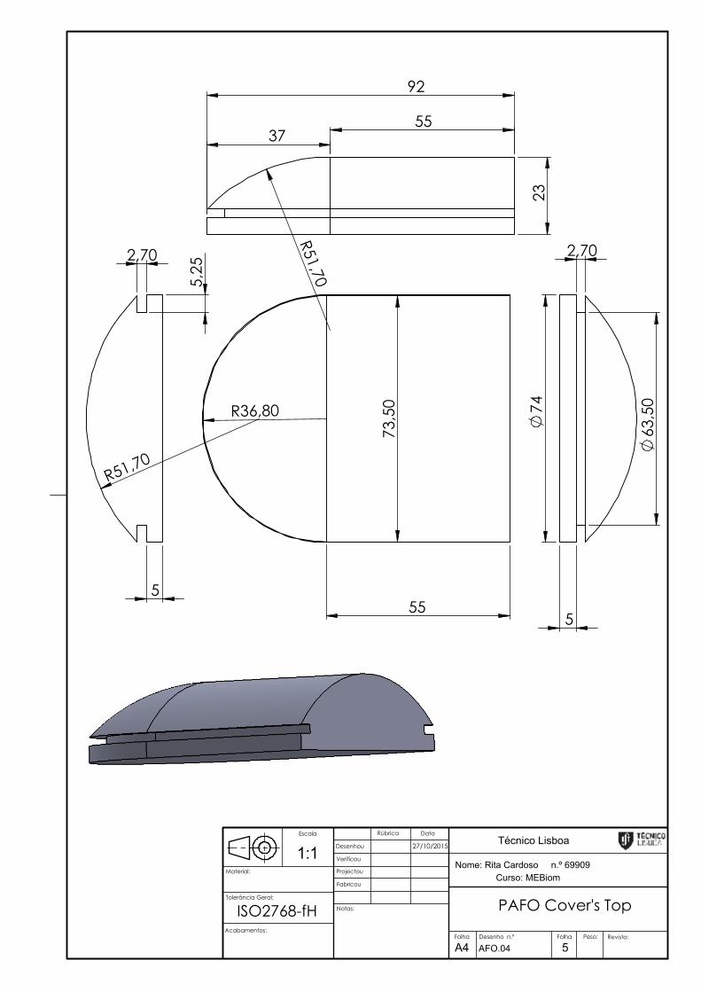
92
55
23
37
R51,70 7
3,50
55
R36,80
5
2,70
5,2
5
R51,70
74
5
2,70
63,5
0
PAFO Cover's Top
Curso: MEBiom
27/10/2015 Técnico Lisboa
Notas:
Peso:
Fabricou
Projectou
Verificou
Desenhou
DataRúbrica
Material:
Revisto:
A4Folha Folha
5
Nome: Rita Cardoso n.º 699091:1Escala
Desenho n.º
Tolerância Geral:
AFO.04
ISO2768-fH Acabamentos:
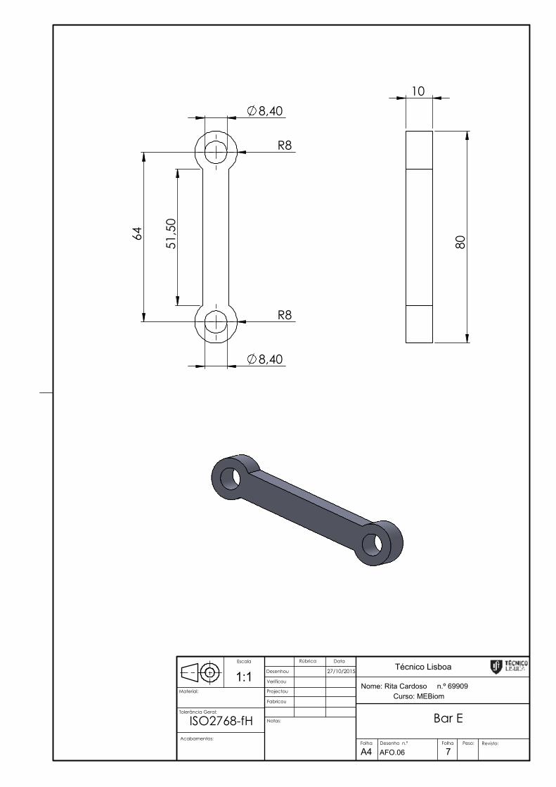
51,
50
64
8,40
R8
R8
8,40
10
80
Bar E
Curso: MEBiom
27/10/2015 Técnico Lisboa
Notas:
Peso:
Fabricou
Projectou
Verificou
Desenhou
DataRúbrica
Material:
Revisto:
A4Folha Folha
7
Nome: Rita Cardoso n.º 699091:1Escala
Desenho n.º
Tolerância Geral:
AFO.06
ISO2768-fH Acabamentos:
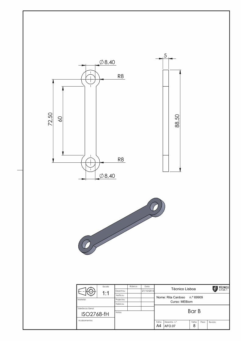
R8
60
72,
50
8,40
R8
8,40
5
88,
50
Bar B
Curso: MEBiom
27/10/2015 Técnico Lisboa
Notas:
Peso:
Fabricou
Projectou
Verificou
Desenhou
DataRúbrica
Material:
Revisto:
A4Folha Folha
8
Nome: Rita Cardoso n.º 699091:1Escala
Desenho n.º
Tolerância Geral:
AFO.07
ISO2768-fH Acabamentos:

4
6
7,80
20
20
6
20
75
35
20
20
6
4
20 112,80
124,70
Superior Connection
Curso: MEBiom
27/10/2015 Técnico Lisboa
Notas:
Peso:
Fabricou
Projectou
Verificou
Desenhou
DataRúbrica
Material:
Revisto:
A4Folha Folha
9
Nome: Rita Cardoso n.º 699091:2Escala
Desenho n.º
Tolerância Geral:
AFO.08
ISO2768-fH Acabamentos:
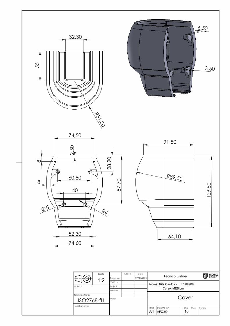
6,50
3,50
74,50
74,60
60,80
40
28,
90
87,
70
5 R4
8 2
,50
8
52,30
32,30
R51,30
55
129
,50
91,80
64,10
R89,50
Cover
Curso: MEBiom
27/10/2015 Técnico Lisboa
Notas:
Peso:
Fabricou
Projectou
Verificou
Desenhou
DataRúbrica
Material:
Revisto:
A4Folha Folha
10
Nome: Rita Cardoso n.º 699091:2Escala
Desenho n.º
Tolerância Geral:
AFO.09
Acabamentos:
ISO2768-fH

8,40
R8
8,40
R8
331
13,20
9,20
13,20
5
23,20
347
R4 R4
1,20
R5 R5 3,20
Bar A
Curso: MEBiom
27/10/2015 Técnico Lisboa
Notas:
Peso:
Fabricou
Projectou
Verificou
Desenhou
DataRúbrica
Material:
Revisto:
A4Folha Folha
11
Nome: Rita Cardoso n.º 699091:2Escala
Desenho n.º
Tolerância Geral:
AFO.10
ISO2768-fH Acabamentos:
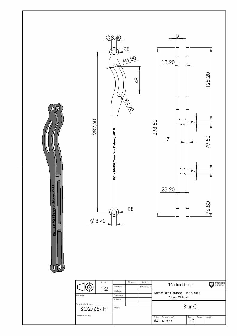
8,40
R8
8,40
R8
282
,50
R4,20
R4,20
49
5
7
13,20
23,20
79,
50
76,
80
128
,20
298
,50
7
7
Bar C
Curso: MEBiom
27/10/2015 Técnico Lisboa
Notas:
Peso:
Fabricou
Projectou
Verificou
Desenhou
DataRúbrica
Material:
Revisto:
A4Folha Folha
12
Nome: Rita Cardoso n.º 699091:2Escala
Desenho n.º
Tolerância Geral:
AFO.11
ISO2768-fH Acabamentos:

5 5
6,20
5 5
60,80
40
58
10
58,
80
47,60
4
6,50
2,50
2,50
8,40
8,40
10
5
R8
R4,20
49,
20
146
,20
3,50
8,50
28,
50
6,20 5 5
6,20
5 5
60,80
40 37,
50
R52,10
8,40
10
9,6
0
Support Unit
Curso: MEBiom
27/10/2015 Técnico Lisboa
Notas:
Peso:
Fabricou
Projectou
Verificou
Desenhou
DataRúbrica
Material:
Revisto:
A4Folha Folha
13
Nome: Rita Cardoso n.º 699091:2Escala
Desenho n.º
Tolerância Geral:
AFO.12
ISO2768-fH Acabamentos:
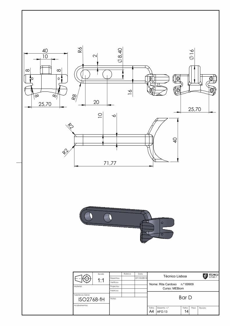
8,40
R6
R8 1
6
20 2
40 10
25,70
8
8
8 8
16
25,70
10 6
R2
R2
71,77
40
Bar D
Curso: MEBiom
27/10/2015 Técnico Lisboa
Notas:
Peso:
Fabricou
Projectou
Verificou
Desenhou
DataRúbrica
Material:
Revisto:
A4Folha Folha
14
Nome: Rita Cardoso n.º 699091:1Escala
Desenho n.º
Tolerância Geral:
AFO.13
ISO2768-fHAcabamentos:
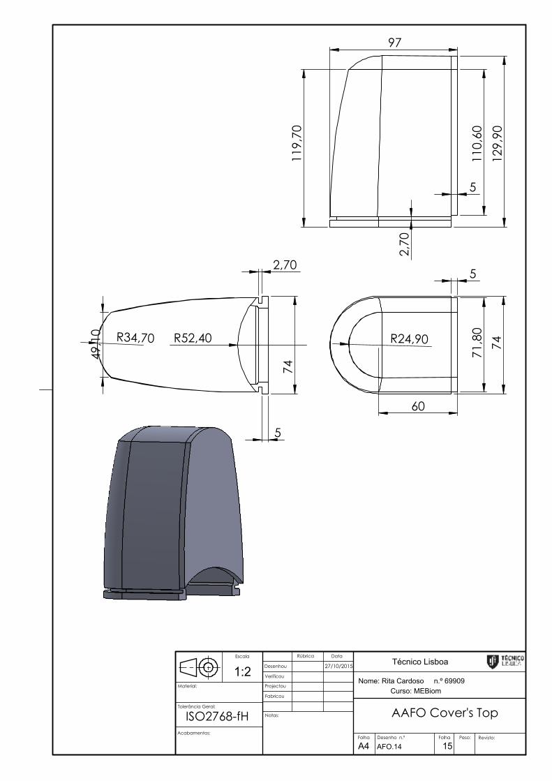
74 R24,90
71,
80
60
5
5
2,70
74
R52,40 R34,70
49,
10
129
,90
119
,70
2,7
0
5
110
,60
97
AAFO Cover's Top
Curso: MEBiom
27/10/2015 Técnico Lisboa
Notas:
Peso:
Fabricou
Projectou
Verificou
Desenhou
DataRúbrica
Material:
Revisto:
A4Folha Folha
15
Nome: Rita Cardoso n.º 699091:2Escala
Desenho n.º
Tolerância Geral:
AFO.14
ISO2768-fH Acabamentos: