design, analysis and fabrication of a new magnet … · 2014-11-19 · design, analysis and...
TRANSCRIPT

DESIGN, ANALYSIS AND FABRICATION OF A NEW MAGNET POWER SUPPLY SYSTEM FOR
ACCELERATOR-BASED IN-SITU MATERIALS SURVEILLANCE IN ALCATOR C-MOD
Lihua Zhou, Rui Vieira, Jeffrey Doody, William Beck, David Terry, William Cochran, James Irby,
Zach Hartwig, Harold Barnard, Brandon Sorbom, Dennis Whyte
Massachusetts Institute of Technology, Plasma Science and Fusion Center,
Cambridge, MA 02139, USA, [email protected]
Acknowledgment: Using the Alcator C-Mod tokamak, a DOE Office of Science user facility.
Talk for 21st Topical Meeting on the Technology of Fusion Energy,
Anaheim, California, USA, Nov. 13, 2014

Outline
• Introduction to Accelerator-based In-situ Materials Surveillance (AIMS) in Alcator C-Mod.
• Motivation and challenge of developing the new magnet power supply system (NMPSS) for AIMS.
• Design of the NMPSS.
• Multi-physics analyses performed by use of COMSOL software.
• Fabrication of the NMPSS.
Nov. 13, 2014 TOFE 2014 2
Courtesy: H.S. Barnard

Introduction to AIMS
• AIMS provides advances in surface diagnostic capabilities of plasma facing components.
• AIMS measures the effects of plasma material interactions withunprecedented temporal (after each plasma shot) and spatial resolution (2 cm).
• Measurements are made in-situ, w/o vacuum break, over a large poloidal/toroidal range, and are non-destructive to material.
• AIMS can directly measure:
• Erosion/deposition.
• Retention of hydrogen isotopes.
• Migration and mixing of plasma facing materials.
Existing AIMS
Nov. 13, 2014 H.S. Barnard, TOFE 2014. 3
Cell of Alcator C-Mod Alcator C-Mod

Measurement approach of AIMS
• An RFQ injects 900 keV D+ into a horizontal (radial) diagnostic port between shots.
• Via the Lorentz force, toroidal field steers the D+ beam poloidally, poloidal field steers the beam toroidally.
• D+ induces nuclear reactions with low-Z ions in top approx. 10 μm surface.
• Neutron and gamma spectroscopy provide quantitative information about surface composition.
Radial
Toroidal (Tangential)
φ
Poloidal (Axial)
Nov. 13, 2014 4H.S. Barnard, TOFE 2014.
Vessel inner wall
TZM Molybdenum alloy

Power system upgrades will dramatically improve spatial coverage of measurements
Nov. 13, 2014 5H.S. Barnard, TOFE 2014.
• Current AIMS can only measure about 35 cm range along poloidal direction.
• Range before upgrade is shown within green dashed box.
• A New Magnet Power Supply System (NMPSS) will enlarge the range to full inner wall height (at least 124 cm) and about 40º along toroidal direction.
• Lower plot: cross section view; right plot: unfolded view.

Requirements for RF amplifier and Poloidal Field (PF) upgrades
Nov. 13, 2014 D. Terry, H. Barnard, TOFE 2014.
Poloidal Field Upgrade (No photo shown)
• Existing 6 pulse rectifier power supply & high current switch to be reused for AIMS.
• +/-30 V @ +/-5 kA (or +/-60 V@ +/2.5 kA) supply available.
• Existing High Current double-pole pneumatically-actuated 6 kA switch to be reused to connect supply to EF4 bus during AIMS operation.
• Existing controls to be reconfigured to coordinate supply operation with C-Mod and AIMS.
RF Amplifier Upgrade
• New 60 kW @ 425 MHz RF amplifier upgrade will increase beam duty factor from 0.3% to 2% and improve reliability.
• Approx. 7 X faster measurements can be made.
• Tested and working to 60 kW @ 425 MHz into AIMS RF Cavity.
60 kW @ 425 MHz RF Amplifier
6

Requirements for Toroidal Field (TF) upgrades
Nov. 13, 2014 D. Terry, TOFE 2014. 7
• 6 pulse 4-quadrant dual lockout converter power supply.
• +/-50 V @ +/-15 kA into magnet/bus load (L = 0.007 H, R = 0.0017 Ω).
• Magnet protected from power supply open circuits during faults.
• Automatic, self-powered, bidirectional crowbar circuit included.
• Backup protection provided by parallel silicon carbide varistor assembly across bus.
• High Current double-pole pneumatically-actuated 18 kA switch required to connect AIMS TF Power Supply to TF Bus during AIMS operation.
• New Buswork required.
• New controls must coordinate operation with existing C-Mod systems.
Nov. 13, 2014

AIMS
TF Bus Route
AC Service Route
AIMS TF
Supply Spaces
Ramp
Down
14’ H x 12’ W
Rollup Garage Door
Entrance to Power
Room
Ramp
Up
Installation Route on
Power Room Floor Level
AIMS TF power supply location in C-Mod power room
D. Terry, TOFE 2014.

TF power supply upgrade
Breaker & ContactorControl & Status
6 Pulse Dual Converter with Lockout Controls(and Shoot-through Protection)
Auto-Crowbar& Varistor
Control & Status
HighCurrentSwitch
Interface
Operator Interface
MainBreaker
Contactor Converter 1 Converter 2MainTransformer
Shunt#1
Shunt#2
Volt.Div.
Crowbar(Optional
Item)
VAR
HighCurrentSwitch
TF MagnetLoad
Local Power Supply Control, Interlocks and Status
Remote Monitor and Control
FusedMachineGround
Main TF Supply Control and
Status
Main TF SupplyWith
Unidirectional Auto-Crowbar
TF BUS
R/2 R/2
L/2L/2
Input Conn.
A
B
C
Neutral
GND
Output Conn.
Magnet Load + TF BusL = 0.0069HR = 0.00167 Ohms
Main TF SupplyV = 1550VI = 250 kA3 Sec. pulse/15 Min.
New AIMS TF SupplyV = 50 VI = 15 kA25~60 minute pulseWith Main TF Supply Disabled
D. Terry, TOFE 2014.

AIMS data taken at
each flattop current level
+/- 50 V range allows current levels to be changed
quickly to optimize data collection time
Supply Load Current in Amperes
Supply Output Voltage
Max. Power Supply Current Rating
Voltage @ 15 kA
Preferred upgraded AIMS TF supply operation
(+/-50 V, +/-15 kA, 0.007 H, 0.0017 Ω)
Nov. 13, 2014 10D. Terry, TOFE 2014.

Outline
• Introduction to Accelerator-based in-situ materials surveillance (AIMS) in Alcator C-Mod.
• Motivation and challenge of developing the new magnet power supply system (NMPSS) for AIMS.
• Design of the NMPSS.
• Multi-physics analyses performed by use of COMSOL software.
• Fabrication of the NMPSS.
Nov. 13, 2014 TOFE 2014 11

Existing bus bar (in green)
New busbar(in brown)
Busbar layout of TF new power supply
• Existing busbars are shown in green.
• New busbars are shown in brown.
• Material: Aluminum 6061 T6511.
• Busbar width: about 305 mm (12”); thickness about 38 mm (1.5”). About 343 mm (13.5”) apart.
• Total length of the busbar: about 36.1 m (118.4 ft.), including new 22.7 m (74.4 ft. ) and existing about 13.4 m (44 ft.).
• Total joints: 16.
• Maximum height of the new busbars is about 3.7 m (12 ft.)
• Total weight for all busbars: about 1,131 kg (2,493 lb), including new busbar 711 kg (1,567 lb).
Dimensions rounded (mm)
Nov. 13, 2014 TOFE 2014 12
TF bus end
Power supplybus end

Busbar cross-sectional area is larger than the minimum required
temperature rise (45 ºC)
symmetrical fault current r.m.s. (400 kA)
cross-sectional area of the conductor (in mm2)
temperature coefficient of resistance at 20 ºC/ºC, which is 0.00363 for aluminum alloys.
operating temperature of the conductor at which the fault occurs (65 ºC)
1.166 for aluminum and 0.52 for copper
duration of fault (1 second) t
t
scI
20
k
tA
Ik sct
20
2
1100
A
Reference: “Carrying power through metal-enclosed bus systems” in book “Electrical Power Engineering Reference & Application Handbook”, page 999,http://www.electricalengineering-book.com/carrying-power-through-metal-enclosed-bus-systems.html.
• Calculated minimum cross sectional area is 7,973 mm2, the area of the selected busbar is 11,613 mm2. The busbar selected meets the requirement.
Nov. 13, 2014 TOFE 2014 13
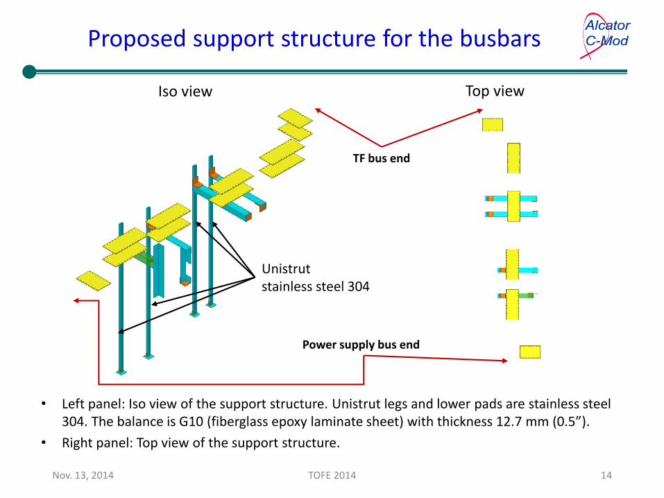
Proposed support structure for the busbars
Top viewIso view
• Left panel: Iso view of the support structure. Unistrut legs and lower pads are stainless steel 304. The balance is G10 (fiberglass epoxy laminate sheet) with thickness 12.7 mm (0.5”).
• Right panel: Top view of the support structure.
Unistrutstainless steel 304
Nov. 13, 2014 TOFE 2014 14
TF bus end
Power supply bus end

Busbar’s all support structure
Floor map (Top view)
Existing support
New support
Vertical leg (Unistrut, stainless steel 304L) Cabinet
• The challenge of designing the busbar and support system is that they have to fit into a densely populated power room.
• Ability to make use of the existing busbar and supports is an advantage.
Nov. 13, 2014 TOFE 2014 15
TF bus end
power supply bus end

Photo shows the busbar connected with tokamak
• The new power supply is connected to one end of the new busbar. Existing TF busbars to Alcator C-Mod tokamak are connected to the other end of the new busbar.
Nov. 13, 2014 TOFE 2014 16
Existing busbarExisting TF busbar to Alcator C-Mod

Maximum power supply cabinet
Power Supply
Unit: mm.
Sidedoor
Control room
Cell AlbanySt.
Front door
Control boxside
DC OutputBus Side
Nov. 13, 2014 TOFE 2014 17
• Estimated dimension of the power supply cabinet (length x width x height): 3.1 x 1.4 x 2.8 m (122 x 54 x 110”).
Top view

Varistor Protection Assembly (VPA)
Varistor disc (silicon carbide)
Current terminal plates(Total: 7)
Nov. 13, 2014 TOFE 2014 18
• Connects across supply output bus, providing fast passive protection.
• Located on power supply side of high current switch.
• Backs up auto-crowbar system.
• There are 6 varistor discs in one unit and 15 units in the assembly, or 90 discs total.
• Varistor disc size: diameter 152 mm and thickness 20 mm.
• Clamping voltage is 1,500 V. And Insulation is rated at 5 kV for 1 min.
• Capable of handling 787.5 kJ stored energy, or 8.75 kJ/disc, less than 75 kJ/disc rating.
• Capable of handling 15 kA. Each disc sees 167 A, or less than the 250 A/disc rating. Idle current is between 3.5 A and 6 A at 50 V.

Outline
• Introduction to Accelerator-based in-situ materials surveillance (AIMS) in Alcator C-Mod.
• Motivation and challenge of developing the new magnet power supply system (NMPSS) for AIMS.
• Design of the NMPSS.
• Multi-physics analyses performed by use of COMSOL software.
• Fabrication of the NMPSS.
Nov. 13, 2014 TOFE 2014 19

Joule heating analysis of the busbar
Nov. 13, 2014 TOFE 2014 20
• For continuous operation with current 15 kA and free air convection of 15 W/(m2*K), after 25 min., the max. temperature is 61.5 ºC, which is below the specified 65 ºC limit.
• Similar analysis has also been done for a fault condition (400 kA for 1 sec.), the max. temperature is 75 ºC, which is below the allowable (200 ºC).
Km
W2Km
W2

Structural coupled with electromagnetic analysis shows stress is within allowable
Nov. 13, 2014 TOFE 2014 21
Scale: 5x10⁵
• From electromagnetic analysis of the busbar, magnetic flux density is shown on the right panel. The arrows show the direction of the vector force, meaning that the load tends to push the two parallel busbars apart.
• Structural analysis coupled with electromagnetic analysis shows the max. stress in the busbar is about 11.9 kPa, which is well below the allowable 170 MPa (two thirds of the yield strength of the material).

Structural analysis of the support structure shows the support is sufficient
Nov. 13, 2014 TOFE 2014 22
• Left panel: busbar gravity load only, the max. stress in the support structure is benign.
• Right panel: busbar gravity load with the spreading load while current applied, the stress in the support structure is also benign.
• In both cases, the max. stress is within the allowable (two thirds of the yield strength of the materials, 170 MPa for Aluminum alloy busbar, 175 MPa for G10 fiberglass epoxy laminate sheet and 143 MPa for stainless steel 304 ).

Joule heating analysis of varistor disc indicates the temperature rise and cooling time are both acceptable
Nov. 13, 2014 TOFE 2014 23
• Left panel: FEA simulation to find out the temperature rise of the varistor disc. The temperature rise is about 12 ºC. OK for the silicon carbide.
• Right panel: with free air convection, the cooling time is about 1.5 ~2 hours for the disc.
• These results are in consistent with the information from the vendor.

Current flow path in the varistor unit
+
-
Nov. 13, 2014 TOFE 2014 24
• For purpose of viewing the current directions, the two rods are rotated and projected to one plane.
• By analyzing the current flow path, it is concluded that the 6 discs are parallel to each other.
Rod

Current flow path from FEA simulation
Scale factor 5e-9,
arrow length (logarithmic)
Scale factor 6e-10
Nov. 13, 2014 TOFE 2014 25
• Three discs sub-assembly is analyzed by FEA. The arrows shows the directions of the currents.
• Currents are not uniformly distributed within the discs, but well within rated parameters.

Stress in varistor disc resulted from electromagnetic load is within allowable
• The max. stress in a varistor disc is 112 MPa, which is below the allowable (175 MPa).
Nov. 13, 2014 TOFE 2014 26

Conclusions
• The proposed New Magnet Power Supply System (NMPSS) will greatly enlarge the spatial measurement range of AIMS from 35 cm to 124 cm poloidally and to 40 degree toroidally.
• Busbars, corresponding support structure, power supply footprint, and varistor protection assembly are designed. Multi-physics analyses indicate the design meets all requirements.
• All component drawings have been completed and the system is ready for fabrication.
• Final installation of the system will be initiated when the power supply is procured and in place.
Nov. 13, 2014 TOFE 2014 27

Thank you for your attention!
Nov. 13, 2014 TOFE 2014 28