design an interline dynamic voltage restorer for … an interline dynamic voltage restorer 543 and...
TRANSCRIPT
International Journal of Electrical Engineering. ISSN 0974-2158 Volume 4, Number 5 (2011), pp. 541-554 © International Research Publication House http://www.irphouse.com
Design an Interline Dynamic Voltage Restorer for Voltage Sag Compensation using Z-Source Inverter
C. Gopinath1, P. Siva perumal2, R. Ramesh3 and A. Peer Fathima4
1Research Scholar, Anna University, Chennai, India & Assistant Professor (Sel.Grade) / Dept. of EEE,
Easwari Engineering College, Ramapuram, Chennai-600089, TN, India E-mail: [email protected]
2PG Student, 4Professor & Head, Dept. of EEE, Easwari Engineering College, Ramapuram, Chennai-600089, TN, India
3Associate Professor, Dept. of EEE, College of Engineering, Anna University, Chennai-600025, TN, India.
Abstract
To design an Interline Dynamic Voltage Restorer using Z-source inverter which is able to compensate voltage sag and voltage regulation at critical load terminals. The converter is composed with the minimum number of switching devices and will be controlled to achieve a high reliability and robustness during transient and steady state operating condition. The converter is connected between AC mains and load through a series transformer. The Interline Dynamic Voltage Restorer (IDVR) consists of several DVRs connected in different distribution feeders in the power system. The DVRs in the IDVR system share common energy storage. When one of the DVR compensates for voltage sag compensation mode appearing in that feeder, other DVRs replenish the energy in the common DC-link dynamically. Thus, one DVRs in the IDVR system works in voltage sag compensation mode while other DVRs in the IDVR system operate in power flow control mode. This paper proposes compensation as PI controller and Hysteresis controller. The hysteresis controller is most efficient with comparison of PI controller.
Keywords: Hysteresis controller, Interline DVR, Power quality, PI controller, Z-Source Inverter.
Introduction Ongoing expansion and growth of electric utility, loads are becoming more sensitive

542 C. Gopinath et al
with either short-term or long-term voltage disturbances in the form of voltage sags. This problem to be overcome by several novel techniques to mitigation of voltage sag, swell and harmonics content. The Interline Dynamic voltage restorer using Voltage Source inverter (VSI) [1] [2], is injecting ac voltage with series injecting transformer with a inverter. Custom power is a technology-driven product and service solution which embraces a family of devices to provide power-quality enhancement functions. Among the several novel custom-power devices, the dynamic voltage restorer (DVR) [3] [4] is the most technically advanced and economical device for voltage-sag mitigation in the distribution systems. The traditional inverter problems are overcome by introduction of Z-source inverter (ZSI). Z-source inverter [8] [10] [11] overcomes the conceptual and theoretical barriers and limitations of the traditional voltage-source converter (abbreviated as V-source converter) and current-source converter (abbreviated as I-source converter) and provides a novel power conversion concept. The conventional DVR [4] functions by injecting ac voltages in series with the incoming three-phase network, the purpose of which is to improve voltage quality by adjustment in voltage magnitude, wave shape, and phase shift. These attributes of the load voltage are very important as they can affect the performance of the protected load. Voltage injection with an appropriate phase advance with respect to source side voltage can reduce the energy consumption [3]. However, the energy requirement cannot be met by the application of such phase-advance technique alone for mitigating deep voltage sag of long duration, as it is merely a way of optimizing existing energy storage. If the dc link of the DVR can be replenished dynamically by some means, the DVR will be capable of mitigating deep sags with long durations. This paper provides a way to replenish the energy in the common dc-link energy storage dynamically using z-source inverter. The z-source inverter is operated at an either buck or boost mode. The IDVR system consists of several DVRs protecting sensitive loads in different distribution feeders emanating from different grid substations, and these DVRs share a common dc link. The interline power-flow controller (IPFC) proposed in [5] addresses the problem of compensating a number of transmission lines at a given substation. The IPFC scheme provides a capability to transfer real power directly between the compensated lines, while the reactive power is controllable within each individual line. The control system of a DVR plays an important role, with the requirements of fast response in the face of voltage sags and variations in the connected load. Generally, there are two control schemes, open loop [5] and closed loop [6], which is used in the DVR applications. This paper presents an extensive analysis to develop suitable control strategies for the DVRs in the IDVR scheme. The proposed IDVR control system consists of a PI controller and hysteresis controller for a individual DVR with comparison result using Matlab / Simulink. It mainly focuses on replacing the voltage source inverter with Z-source inverter as its advantages are described in further sections. Basic Operation of IDVR The Interline Dynamic voltage restorer (IDVR), which is installed between the supply
Design an Interline Dynamic Voltage Restorer 543
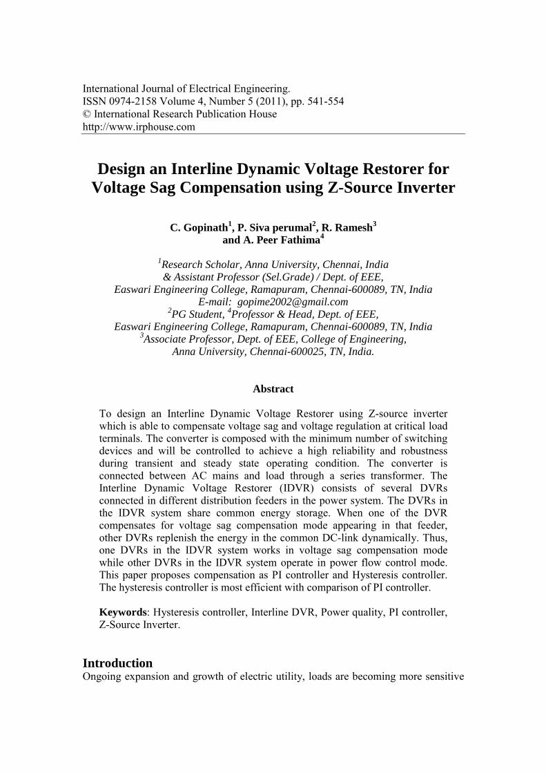
and critical load; can restore the load voltage to the pre-fault voltage during voltage sag. The IDVR consists of several DVRs connected a different distribution feeders in the power system. The DVRs in the IDVR system share common energy storage between the feeders. When one of the DVR compensates for voltage sag compensation mode appearing in that feeder, the other DVRs replenish the energy in the common DC-link dynamically. Due to these factors and as the two feeders of the IDVR system in Fig. 1 are connected to two different grid substations, it is reasonable to assume that the voltage sag in Feeder 1 would have a lesser impact on Feeder 2. To restore load voltage, DVR should inject the equivalent of dropped voltage, which represents the voltage difference between the pre-fault and fault voltage through series connected transformer. Voltage restoration of DVR needs to inject active power and energy from DVR to distribution system. However, the capability of energy storage that usually consists of capacitors in DVR is limited. Therefore, it must be considered how the injection energy can be minimized and the load voltage can be made close to the pre-fault voltage. The design of the DVR allows real and reactive power to be either supplied or absorbed when operating. If a small fault occurs on the protected system, then the DVR can correct it using only reactive power generated internally. For correction of large faults, the DVR may be required to develop real power. To enable the development of real power an energy storage device must be used; currently the DVR design uses a capacitor bank. Once the fault has been corrected and the supply is operating under normal conditions, the DVR replenishes the energy expended from the healthy system. The rating (in terms of energy storage capabilities) of the capacitor bank is dependent upon system factor such as the rating of the load that protects and the duration and depth of anticipated sags. When correcting large sag (using real power), the power electronics are fed from the capacitor bank via a Z source inverter circuit.
Figure 1: Schematic diagram of an IDVR with two feeder system. The Interline Dynamic voltage restorer (IDVR) is to be providing a

544 C. Gopinath et al
comprehensive power flow control scheme for multi-line transmission system, in which two or more line employ using Z-source inverter for series compensation. The IDVR scheme has the capability to transfer real power between the compensated lines in addition to executing the independent and controllable reactive power compensation of each line. This capability makes it possible to equalize both real and reactive power flow between the lines, to transfer power demand from overloaded to under-loaded lines to compensate against resistive line voltage drops and the corresponding reactive line power and to increase the effectiveness of the compensating system for dynamic disturbance like transient stability.
Figure 2: Phasor Diagram of feeder 2 for real-power transfer.
Mathematical formulation for IDVR system From fig.2 shows phasor diagram for real-power transfer between the two feeders, Vs2 to be a source voltage from the feeder 2,Vb2 as bus voltage and then injecting voltage Vinj2. When interline DVR system is to be injected by dynamically with Z-source inverter and it’s formed by mathematical formulation of real power exchange between the two feeder 1 and 2. The equation based on two case 2 is written as, Case (I) Real power exchange between two feeders, Feeder 2, Pex2=3Vl2Il2 [ cos(Ф2-β)-cos(Ф2)] ----> (1) let, Sl2= 3Vl2Il2 Sl2=Apparent power, β –Advance phase angle, Vl2- load voltage line2 For maximum real power,
β= Ф2, Pex2=3Vl2Il2 [ cos(Ф2- Ф2)-cos(Ф2)] Pex2=3Vl2Il2 [ cos(0)-cos(Ф2)] Pex2(max)=Sl2[1-pf2] -----> (2) βmax= Ф2 & pf2= cos(Ф2)

Design an Interline Dynamic Voltage Restorer 545
Feeder 1, Pex1= PDVR1+Plosses ---- (3) From (1) & (3), we get, Pex=Sl2[ cos(Ф2-β)-cos(Ф2)] Pex/Sl2= [ cos(Ф2-β)-cos(Ф2)] Pex/Sl2+Pf2= cos(Ф2-β) Ф2-β= cos¯¹ [Pex/Sl2+Pf2] β= Ф2 -cos¯¹ [Pex/Sl2+Pf2] β= Ф2 -cos¯¹ [PDVR1+Plosses /sl2+Pf2] ----> (4) Case (II) In this case for energies the voltage from common dc-link voltage, the dynamically storage and Dynamic voltage restorer operating at pre-sag voltage injection between the two feeders. Then feeder 1 is generating sag factor from equation (6) and its mitigating voltage sag can be optimized real power requirements is given below the equation. DVR1 operating pre-sag supply voltage injection PDVR1pr=Sl1[pf1-R/3(cos(Ф1+θ))] ----> (5) where,R=√(X²+Y²) with X= Ʃ³j=1ajcos(δj), Y=Ʃ³j=1ajsin(δj), & θ=tan¯¹[Y/X] The sag factor aj = Vb1j / Vl1 β= Ф2 -cos¯¹ [[Sl1*(Pf1 –a*cos(δ + θ))+Plosses]/Sl2+Pf2] ----> (6) For maximum real power transfer, a=[Sl1Pf1 + Plosses- Sl2(1-Pf2)]/[Sl1cos(Ф1+ δ) ----> (7) For optimum real power required to mitigate voltage sag can be, PDVR1>0 PDVR1opt=Sl1[pf1-R/3] , where αopt = Ф1+ θ For a balanced 3 Ф voltage sag with sag factor R=3*a , β= Ф2 -cos¯¹[ [Sl1*(Pf1 –a*)+Plosses]/Sl2+Pf2] ----> (8) For maximum real power transfer a=[Sl1Pf1 + Plosses- Sl2(1-Pf2)]/[Sl1cos(Ф1+ δ) ----> (9) The basic three methods used to voltage control for sag compensation of Dynamic voltage restorer (DVR) are, Pre-sag compensation, In-phase compensation, Energy optimal compensation. The real power injected by DVR1 to compensate particular sag is decided by the type of voltage-restoration method, such as in-phase injection [5], pre-sag-supply-voltage injection [5], and energy-saving injection [3], [7]. When the voltage sag contains a phase-angle jump, the in-phase-injection technique introduces the same phase-angle jump to the load, which is not desirable. If the voltage sag does not contain a phase-angle jump, the in-phase-injection method is similar to the pre-sag-supply-voltage injection. Therefore, the real-power requirement in the pre-sag supply voltage and energy-saving injection methods is addressed in the following
546 C. Gopinath et al
sections. Pre-sag compensation: The supply voltage is continuously tracked and the load voltage is compensated to the pre-sag condition. The method gives a nearly undisturbed load voltage, but can often exhaust the rating of the DVR. In-phase compensation: The generated DVR voltage is always in phase with the measured supply voltage regardless of the load current and the pre-sag voltage. Energy optimal compensation: To fully utilize the energy storage, information about the load current is used to minimize the depletion of the energy storage. In this paper, energy optimal compensation is used. When utilize the energy storage device as common dc-link (capacitor) is used between the two feeders. The energy-saving injection method is derived for expression as described above following factors. Interline DVR contains two feeder, one of the feeder healthy line and another one is fault line to be form a sag. Therefore, one of the feeder to compensate sag using Z-source inverter with filter and then energies dc-link voltage is continuously tracking voltage. This method real-power requirement for energy optimal compensation, the load current is used to minimize the depletion of the energy storage. Z-Source Inverter The two traditional converters: voltage-source and current –source converters. A dc voltage source supported by a relatively large capacitor feeds the main converter circuit, a three-phase bridge. Six switches are used in the main circuit; each is traditionally composed of a power transistor and an anti-parallel (or freewheeling) diode to provide bidirectional current flow and unidirectional voltage blocking capability. The V-source converter is widely used. In addition, both the V-source converter and the I-source converter have the following common problems.
• They are either a boost or a buck converter and cannot be a buck–boost converter. That is, their obtainable output voltage range is limited to either greater or smaller than the input voltage.
• Their main circuits cannot be interchangeable. In other words, neither the V-source converter main circuit can be used for the I-source converter, nor vice versa.
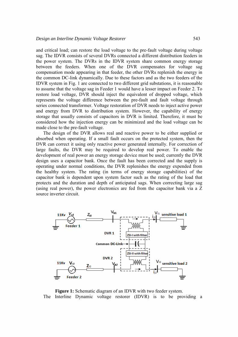
• They are vulnerable to EMI noise in terms of reliability. To overcome the above problems of the traditional V-source and I-source converters, this paper presents an impedance-source and its control method for implementing dc-to-ac, ac-to-dc, ac-to-ac, and dc-to-dc power conversion in Interline Dynamic voltage restorer (IDVR). Fig. 3 shows the general Z-source converter structure proposed. It employs a unique impedance network (or circuit) to couple the converter main circuit to the power source, load, or another converter, for providing unique features that cannot be observed in the traditional V- and I-source converters

Design an Interline Dynamic Voltage Restorer 547
where a capacitor and inductor are used, respectively. The Z-source converter overcomes the above-mentioned conceptual and theoretical barriers and limitations of the traditional V-source converter and I-source converter and provides a novel power conversion concept.
Figure 3: Schematic diagram of Z-source inverter. In Fig. 3, a two-port network that consists of a split-inductor and capacitors and connected in X shape is employed to provide an impedance source (Z-source) coupling the converter (or inverter) to the dc source, load, or another converter. The Z-source inverter is connected in series injecting transformer, due to voltage sag compensation. Control Method The Control of two methods to be analysed in this paper is realized by comparing result, i.e. a PI control method and a Hysteresis control method. PI Control Method The DVR output voltage depends on the accuracy and dynamic behaviour of the pulse width-modulated (PWM) synthesis scheme and the control system used as show in the fig.4. Usually, the control voltage of the DVR is derived by comparing the incoming supply voltage against a desired reference voltage [5].

548 C. Gopinath et al
Figure 4: PI controller. Although system stability is guaranteed in this type of control, damping is poor, and the stability margin may not be sufficient in the presence of inverter-side filter [6]. Poor damping results in sustained voltage oscillations in the distribution network, which could have serious adverse effects on sensitive loads and equipment such as adjustable speed drives. The drawbacks of the open loop control system can be avoided with multi-loop feedback control system where a voltage loop is incorporated externally to an inner current loop taken from the filter capacitor current of the DVR [6]. Hysteresis Controller Figure.5 shows the control action effected using hysteresis controller. Here, Vref is the desired compensation current reference signal. Vcomp is the actual inverter leg output current. An unmatched quantity ΔV is the current shaping error which is sent to the positive terminal of the comparing unit. The negative terminal of the comparing unit is connected to the output of a hysteresis characteristic generator. When Vref is greater than Vcomp, the resultant ΔV is positive. If the magnitude of the ΔV exceeds the upper boundary of a specified hysteresis band, the comparing unit output goes high, firing the upper bridge device of the leg and making the leg current increase. When Vcomp becomes greater than Vref, ΔV becomes negative. If the magnitude of the ΔV exceeds the lower boundary of the hysteresis band, the comparing unit goes low, firing the lower bridge device of the leg and making the leg current decrease. By increasing or decreasing the allowable current shaping error, which is determined by the bandwidth of the hysteresis characteristic, the average switching frequency can be controlled. This firing algorithm is sometimes called a delta modulation. In the simplest delta modulation control, an equal bandwidth over the whole power frequency cycle is used for the hysteresis. In this case, the modulation frequency is a constant. A nonlinear modulation can be used to help reduce the variations in the switching interval associated with a constant bandwidth [16].

Design an Interline Dynamic Voltage Restorer 549
Figure 5: Hysteresis Controller.
Simulation Results The detailed simulation of IDVR system consists of different feeder with parameter to be carried out using MATALAB/SIMULINK. The simulation is highly performance by MATLAB; it is interactive system whose basic element is an array that doesn’t require dimensioning. This allows solving many technical problems, especially those with matrix and vectoring formulation in a fraction of time it would take to write a program in a scalar non interactive language such as C or Fortan.
Figure 6: Interline Dynamic Voltage Restorer (IDVR).
550 C. Gopinath et al
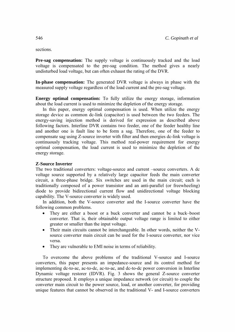
Figure 7: Z-source inverter.
Figure 8: Injecting transformer.
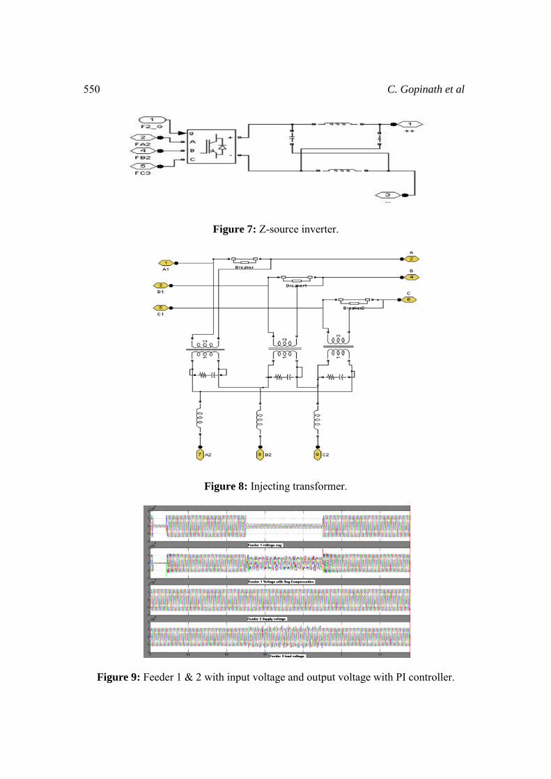
Figure 9: Feeder 1 & 2 with input voltage and output voltage with PI controller.

Design an Interline Dynamic Voltage Restorer 551
Figure 10 (a): Feeder 1 supply voltage without compensation.
Figure 10 (b): Feeder 1 load voltage with 50% compensation.
Figure 10(c): Feeder 2 supply voltage.
Figure 10(d): Feeder 2 load voltage.
Figure 10(e): Common DC-link voltage.
552 C. Gopinath et al
A detailed simulation has been carried out for a simple IDVR system consisting of two lines of 11KV voltages. Two lines are feeding equal loads of 1 MVA with 0.8PF lagging. The performance and restoration capability of the IDVR was tested by simulation using Matlab/Simulink. Initially, the system was subjected to sag of 50%. Simulations are carried out and the transient performance at sag front and recovery were observed. Also the performance was evaluated when the DC voltage drops during long sag. Figure.9 shows the simulated results of voltage waveform across load 1 and load 2 with IDVR using PI controller system. Figure 10(a),(b),(c),(d)&(e) shows the simulated results of voltage waveform across load 1 and load 2 with IDVR using Hysteresis controller system and common DC link voltage. It also shows that the IDVR using ZSI, storage energy in the common DC link can be utilized during the process of voltage compensation with the use of buck-boost property of the inverter. Conclusion This paper proposes the concept of IDVR, which is an economical approach to improve multiline power quality. The IDVR proposed in this paper consists of several DVRs which are electrically far apart, connected to a common dc link. When one of the DVRs compensates voltage sag, the other DVRs are used to replenish the dc-link stored energy. The control scheme for the IDVR includes a multi-loop feedback control system, which is identical for both the voltage compensation and the real power control. The performances of proposed IDVR system and its PI and hysteresis controller were tested with simulations using Matlab / Simulink. It was observed that the IDVR compensates the disturbance caused by sag effectively while utilising the stored energy (common DC-link) fully with the use of buck-boost capability of the ZSI using Hysteresis controller. The limiting factor of the proposed IDVR system is that the amount of real power that one line can transfer to the DC-link energy storage depends on the load power factor. The simulation shows that a two line IDVR system can mitigate about 50% voltage sag with long duration appearing in one of the lines. IDVR simulation studies for power flow management and voltage regulation in the distribution lines. Simulation results establish the unique capability of the IDVR using Z-source inverter for hysteresis controller to correct power imbalance in the distribution system with two or more lines and receiving end voltage regulation of a line at the sub-station. References
[1] D. Mahinda Vilathgamuwa., 2006, “A Novel Technique to Compensate Voltage Sags in Multiline Distribution System—The Interline Dynamic Voltage Restorer” IEEE Transaction on Industrial Electronics,Vol.53.No.5 pp.1603-1611.
[2] D. Mahinda Vilathgamuwa., 2004, “Interline Dynamic Voltage Restorer: A Novel and Economical Approach for Multiline Power Quality Compensation” IEEE Transaction on Industrial Applications, Vol.40. No.6.

Design an Interline Dynamic Voltage Restorer 553
[3] A. Ghosh and G. Ledwich., 2002, “Compensation of distribution system voltage using DVR,” IEEE Trans. Power Delivery, Vol.17. No.4. pp.1030–1036.
[4] S. S. Choi, B. H. Li, and D. M. Vilathgamuwa., 2000, “Dynamic voltage restoration with minimum energy injection,” IEEE Trans. Power Syst., Vol. 15. No. 1. pp. 51–57.
[5] L. Gyugyi, K. K. Sen, and C. D. Schaude., 1999, “The interline power flow controller concept: A new approach to power flow management in transmission system,” IEEE Trans. Power Del., Vol.14. No.3. pp. 1115–1123.
[6] J. G. Niesen, F. Blaabjerg, and N. Mohan., 2001, “Control strategies for dynamic voltage restorer compensating voltage sags with phase jump,” in Proc. 16th Annu. IEEE APEC, Vol. 2. pp. 1267–1273.
[7] M. Vilathgamuwa, A. A. D. R. Perera, and S. S. Choi., 2002, “Performance improvement of the dynamic voltage restorer with closed-loop load voltage and current-mode control,” IEEE Trans. Power Electron., Vol. 17. No. 5. pp. 824–834.
[8] M. Vilathgamuwa, A. A. D. R. Perera, S. S. Choi, and K. J. Tseng., 1999, “Control of energy optimized dynamic voltage restorer,” in Proc. 25th Annu. Conf. IEEE Ind. Electron. Soc., Vol. 2. pp. 873–878.
[9] Fang Zheng Peng., 2003, "Z-source inverter," IEEE Transactions on Industry Applications, Vol.39. No.2. pp.504-510.
[10] I.J.Nagrath and D.P.Kothari., “Modern Power System Analysis”, Second Edition, Tata McGraw-Hill Publishing Company Limited, New Delhi.
[11] B. Justus Rabi; R. Arumugam., “Harmonic Study and Comparison of Z-Source Inverter with Traditional Inverters,” American Journal of Applied Sciences 2 (10)
[12] S Peng F. Z., Yuvan X., Fang X. and Qian Z., 2005,. “Z-source inverter for motor drives”, IEEE Transactions on Power Electronics, Vol. 20. No. 4. pp. 857-863.
[13] Arkadiusz Kulka, Tore Undeland., 2008, “Voltage Harmonic Control of Z-source Inverter for UPS Applications” 13th International Power Electronics and Motion Control Conference (EPE-PEMC 2008), pp. 672-677.
[14] D. M. Vilathgamuwa, C. J. Gajanayake, P.C. Loh, and Y.W. Li., 2006, "Voltage Sag Compensation with Z-source Inverter Based Dynamic Voltage Restorer", in Conf. Rec. of IEEE IAS'06, pp. 2242-2248.
[15] Jowder, F.A.L., 2009, "Design and analysis of dynamic voltage restorer for deep voltage sag and harmonic compensation," Generation, Transmission & Distribution, IET, Vol.3. No.6. pp.547-560.
[16] Ran Cao; Jianfeng Zhao; Weiwei Shi; Ping Jiang; Guoqing Tang., 2001, "Series power quality compensator for voltage sags, swells, harmonics and unbalance," Transmission and Distribution Conference and Exposition, 2001 IEEE/PES , Vol.1. pp.543-547.
[17] RASHID M.H., 1993, “Power electronics, circuits, devices, and applications” (Prentice-Hall, 1993, 2nd edn.).

554 C. Gopinath et al
About the Authors C. Gopinath has obtained his B.E. degree in Electrical and Electronics Engineering from Madurai Kamaraj University, Madurai and completed his M.E. degree in Power Systems Engineering from Annamalai University, Chidambaram. He has 10 years of teaching experience. He is presently research scholar at Anna University Chennai. He is presently working as Assistant Professor (Selection Grade)/ Dept. Of EEE, Easwari Engineering College, Chennai. His research area is power quality improvements. He is a life member of ISTE and Associate member of Institution of Engineers. Sivaperumal P. has received his degree in Electrical & Electronics from Vel tech engineering college, affiliated to Anna University, Chennai in 2008 and pursuing Masters in Power Electronics & Drives at Easwari Engineering College, affiliated to Anna University, Chennai. His areas of interest include Power Quality & FACTS. Dr. R. Ramesh has obtained his B.E. degree in Electrical and Electronics Engineering from University of Madras, Chennai and completed his M.E. degree in Power Systems Engineering from Annamalai University, Chidambaram. He received his PhD degree from Anna University Chennai and has been a faculty of Department of Electrical and Electronics, College of Engineering, Anna University Chennai since 2003. His areas of interest are Real - Time Distributed Embedded control, Online Power system analysis and Web Services. Dr. A. Peer Fathima has obtained her B. E. Degree in Electrical & Electronics from Government College of Engineering, Tirunelveli, M. E. Degree in High Voltage Engineering from Anna University, M.S. degree in Electronics & Control from BITS, Pilani. She received her Ph.D degree from Anna University, Chennai. She has been in the teaching profession for the past 21 years. She has published over 25 papers in International Journals and National Conferences. She has guided several UG and PG projects. She is currently working as Professor and Head, Dept. of EEE, Easwari Engineering College, Chennai. She is guiding four Ph.D scholars at Anna University, Chennai. Her main teaching and research interest encompasses, Power System Control and Frequency control in De-Regulated Power Systems.