dermalab series skinlab combo - new zealand manual skinlab... · high resolution ultrasound skin...
TRANSCRIPT

Instruction Manual SkinLab Z5010108 UK.docx
DermaLab® Series SkinLab Combo
Instruction Manual
CORTEX TECHNOLOGY
Smedevaenget 10 9560 Hadsund, Denmark
www.cortex.dk [email protected]

Instruction Manual SkinLab Z5010108 UK CORTEX TECHNOLOGY
2/41
Instruction Manual SkinLab Z5010108 UK CORTEX TECHNOLOGY
3/41
DERMALAB® SERIES
SKINLAB COMBO
INSTRUCTION MANUAL
Copyright
Copyright © 2012 by Cortex Technology ApS. All rights reserved. No part of this publication may be reproduced, transmitted,
stored in a retrieval system, or translated into any language in any form by any means without the permission of Cortex Technolo-
gy.
Trademarks
Dermalab is a registered trademark of Cortex Technology.

Instruction Manual SkinLab Z5010108 UK CORTEX TECHNOLOGY
4/41
Contents
1. WARNINGS ............................................................................................................ 6
2. INSTALLATION AND POWER-ON ......................................................................... 7
2.1. POWER SUPPLY ............................................................................................................................... 7 2.2. MAIN UNIT ..................................................................................................................................... 7 2.3. CONNECTION OF PROBES ................................................................................................................ 7 2.4. POWER ON ..................................................................................................................................... 7
3. INTENDED USE AND GENERAL DESCRIPTION ................................................... 8
3.1. INTENDED USE ............................................................................................................................... 8 3.2. GENERAL DESCRIPTION .................................................................................................................. 8
4. MAIN SCREEN ....................................................................................................... 9
5. INTRODUCTION TO THE SKINLAB COMBO SCREENS ....................................... 10
6. HIGH RESOLUTION ULTRASOUND SKIN-IMAGING .......................................... 11
6.1. PRINCIPLE ..................................................................................................................................... 11 6.2. THE ULTRASOUND PROBE .............................................................................................................. 11
6.2.1 Preparing the probe ............................................................................................................. 11 6.2.2. Mounting the water barrier ............................................................................................... 11 6.2.3. Using the probe .................................................................................................................. 13 6.2.4. Cleaning .............................................................................................................................. 13
6.3. THE ULTRASOUND SKIN IMAGING SCREEN .................................................................................... 14 6.4. AUTOMATED MEASUREMENTS ....................................................................................................... 17 6.5. THE GOOD ULTRASOUND IMAGE ................................................................................................... 19
6.5.1. Understanding the ultrasound image .............................................................................. 19 6.5.2. How to record a good image ............................................................................................. 20 6.5.3. Preparation ........................................................................................................................ 22
6.6. MAINTENANCE ............................................................................................................................. 22
7. HYDRATION (MOISTURE) .................................................................................. 23
7.1. PRINCIPLE .................................................................................................................................... 23 7.2. MOISTURE PIN-PROBE .................................................................................................................. 23 7.3. THE HYDRATION SCREEN ............................................................................................................. 23 7.4. MAINTENANCE ............................................................................................................................. 24
8. ELASTICITY ......................................................................................................... 25
8.1. PRINCIPLE .................................................................................................................................... 25 8.2. THE ELASTICITY PROBE ............................................................................................................... 26 8.3. THE ELASTICITY SCREEN .............................................................................................................. 27 8.4. MAINTENANCE ............................................................................................................................ 27
9. SEBUM ................................................................................................................. 28
9.1. PRINCIPLE .................................................................................................................................... 28 9.2. SEBUM COLLECTING STRIP ........................................................................................................... 28 9.3. TAPE READER .............................................................................................................................. 28 9.4. THE SEBUM SCREEN AND MEASUREMENT PROCEDURE ................................................................. 29 9.5. MAINTENANCE ............................................................................................................................. 29
10. SKIN COLOR ...................................................................................................... 30
10.1. PRINCIPLE .................................................................................................................................. 30 10.2. SKIN COLOR PROBE .................................................................................................................... 30

Instruction Manual SkinLab Z5010108 UK CORTEX TECHNOLOGY
5/41
10.3. THE SKIN COLOR SCREEN ............................................................................................................ 30 10.4. CALIBRATION ............................................................................................................................. 31 10.5. MAINTENANCE ........................................................................................................................... 31
11. VIDEOSCOPE ...................................................................................................... 32
11.1. PRINCIPLE ................................................................................................................................... 32 11.1.1. Magnification ..................................................................................................................... 32 11.1.2. Polarizer ............................................................................................................................. 32
11.2. PROBE ........................................................................................................................................ 33 11.3. MAINTENANCE............................................................................................................................ 33
12. TRANS EPIDERMAL WATER LOSS (TEWL) ...................................................... 34
12.1. PRINCIPLE .................................................................................................................................. 34 12.2. THE TEWL PROBE ..................................................................................................................... 34 12.3. THE TEWL SCREEN ................................................................................................................... 35 12.4. MAINTENANCE ........................................................................................................................... 35 12.5. CALIBRATION ............................................................................................................................. 35
14. GENERAL MAINTENANCE ................................................................................. 37
15. SERVICE ............................................................................................................. 37
15.1. CALIBRATION OF THE TOUCH SCREEN ......................................................................................... 37 15.2. CUSTOMIZE THE MAIN-SCREEN. .................................................................................................. 38
16. SAFETY ............................................................................................................... 38
17. WARRANTY ........................................................................................................ 39
APPENDIX A – LIST OF SYMBOLS .......................................................................... 40
APPENDIX B – DECLARATION OF CONFORMITY .................................................. 41
Instruction Manual SkinLab Z5010108 UK CORTEX TECHNOLOGY
6/41
1. Warnings
Read this entire manual before using or showing to others how to use the device.
Do not use the device if it shows visible signs of damage or there is other reason to believe
that the device is not functioning correctly.
The performance of this product may be affected if it is stored or transported outside the
range -10°C to 50°C (14°F to 122°F).
The performance of this product may be affected if it is being used outside the range 10°C to
35°C (50°F to 95°F).
The device is a fully self-contained unit. However, if networked to other computer systems or
exchanging data with other systems, the device may be subject to computer virus attacks po-
tentially harmful to the software environment and recorded data.
To reduce such risk, the installation of proper virus scanner software is recommended.
Operation of the device requires administrator rights and, consequently, the operator may be
able to change the settings of the operating system. Do not alter basic settings of the operat-
ing system (e.g. power options, user accounts).
Changes to these settings cannot lead to risk of personal injury, but may lead to malfunction
or lack of performance, which may or may not recognized by the operator.
The device as a system consist of the main-unit, handheld probes and a medical grade power
supply to provide power to the main-unit, and it is designed to meet international safety re-
quirements.
If external peripheral devices are connected to the main-unit it shall be observed, that such
devices meet and are connected to mains in accordance with current legal safety require-
ments for the particular application of the device.

Instruction Manual SkinLab Z5010108 UK CORTEX TECHNOLOGY
7/41
2. Installation and power-on
To ensure trouble-free and safe operation of the DermaLab® Series SkinLab Combo please follow
the instructions for use and maintenance as laid down in this manual.
2.1. Power supply
The power supply must be connected to a wall outlet providing a protective ground terminal in
order to ensure electrical safety. It may be connected to input voltages from 100 - 240 VAC, 50/60
Hz. Do never use any other power supply than supplied by Cortex Technology.
2.2. Main unit
Connect the main unit to the +12 V output cable from the power supply. The power input is
located on the rear panel of the main unit.
To obtain the most stable readings it is advisable to let the unit and probes warm up for approx. 5
min. prior to use.
2.3. Connection of probes
The TEWL, Skin Color, Ultrasound, Hydration and Elasticity probes are all connected at the front
of the SkinLab Combo using various types of connectors. Probes using USB connectors (e.g. the
Videoscope) are connected to one of the USB connectors at the rear side of the main-unit.
The connectors for the probes are all of different types so it is not possible to connect the probes
wrongly to the main-unit. But please note: When connecting the black connectors to the front
panel of the main unit, the turnable lock on the connector at the probes has to be turned as far as
possible to the left before attaching the connector to the socket of the main unit. When the con-
nector has been inserted in the socket the lock shall be turned to the right to lock the connector in
place.
2.4. Power On
The SkinLab Combo is turned on by pressing the button on the front of the device located to the
right of the probe connectors under the display.
Power-on button.

Instruction Manual SkinLab Z5010108 UK CORTEX TECHNOLOGY
8/41
3. Intended use and general description
3.1. Intended use
The SkinLab Combo is a measurement instrument for laboratory use. The SkinLab Combo is not
intended for medical use and serves no diagnostic purpose.
3.2. General description
The SkinLab Combo is based upon a built-in Windows XP embedded PC with a touch screen dis-
play.
The pre-installed application software is implemented in LabView (National Instruments) run-
ning on a Windows XP Embedded operating system.

Instruction Manual SkinLab Z5010108 UK CORTEX TECHNOLOGY
9/41
4. Main screen
Turn on the SkinLab Combo by pressing the small button on the front to the right of the probe
connectors. When the device is turned on, the PC will boot and the main screen appears. The main
screen provides soft-buttons to be activated by the tip of a finger or using a stylus.
Main screen.
The TEWL, Video scope, Ultrasound, Hydration, Elasticity, Sebum and Skin Color
buttons are used for entering the specific measurements directly. See the following chapters for
further details on each measurement function.
The Quit button is used to shut down the SkinLab Combo application. After shut down the Win-
dows XP Embedded desktop will appear and it will be possible to launch other Windows applica-
tions - e.g. making backup of measurement data to a USB stick, install a printer driver etc.
Shut down Windows XP Embedded to turn off the power for the unit. This is done by clicking at
the very left-bottom of the display calling up the hidden Windows START menu.

Instruction Manual SkinLab Z5010108 UK CORTEX TECHNOLOGY
10/41
5. Introduction to the SkinLab Combo Screens
All the individual measurement screens in the SkinLab Combo are using a number of common
control buttons located at the lower left side of the screens. Note: Not all buttons are shown in all
screens.
The buttons provide the following functions:
Load (open) measurement data from file
Save measurement data to a file
Delete last measurement
Delete all measurements on screen
Print measurement data on the default printer
Exit the measurement screen to the main-screen
Show pop-up touch screen keyboard for entering text into label fields or file names.
Note: the keyboard button is located at the top right corner of the screen
Hint: In case an external USB keyboard is connected to one of the USB-ports of the
unit, the pop-up of the on-screen keyboard can be permanently disabled by renaming
the application file: c:\program files\clik-n-type\click-n-type.exe to click-n-type-no-
pop-up.exe.
Note: A “right mouse click” on the touch screen can be made by pressing the touch screen for one
second or longer at the same position. The use of right clicks can be an advantage when operating
Windows XP because it will often open a small menu with a selection of options. This may be use-
ful for example when backing up measurement files to a USB memory stick.
Instruction Manual SkinLab Z5010108 UK CORTEX TECHNOLOGY
11/41
6. High resolution Ultrasound Skin-Imaging
6.1. Principle
Ultrasound skin imaging is based on measuring the acoustic response from the skin, when an
acoustic pulse is sent into the skin. The energy of the acoustic pulse is very low and will not affect
the skin or other tissue in any way. When the emitted acoustic pulse hits the different structures of
the skin, part of the pulse will be reflected and part of the pulse will be transmitted further into the
skin. The reflected signal will travel back and be picked up by the ultrasound transducer. After
processing, the cross-sectional image as visualized on the screen represents an intensity (ampli-
tude) analysis of these returned signals.
The intensity of the received signal refers to a color scale, where dark colors represent areas of the
skin with low reflection (i.e. none or small changes in density between the structures in the skin)
and bright colors represent areas with strong reflections (i.e. significant changes in density be-
tween structures).
6.2. The ultrasound probe
The SkinLab Combo ultrasound probe is scanning in a circle and in a single plane into the skin,
the so-called B-mode.
6.2.1 Preparing the probe
Water has been selected as the ultrasound transmission medium to provide minimal attenuation
of the acoustical signal from the probe to the skin and back. As a result, the scanning heads have
an internal water chamber (‘‘water path’’). For the operator’s convenience and the comfort of the
client the ultrasound probe has an integrated disposable water barrier to prevent spillage.
The water barrier film is made of a special plastic film-material, which allows high frequency ul-
trasound to pass with minimal attenuation and without compromising the image quality. The
water barrier is a film, intended to be disposed off between recordings to minimize the risk of
cross-contamination.
The water chamber inside the scanning head is designed as an open chamber to reduce the risk of
permanent contamination of the water. The recommended water quality is de-ionized water or
distilled water. Plain tap water should be avoided due to the risk of mineral deposits on the front
of the transducer. Such deposits will lead to poor image quality.
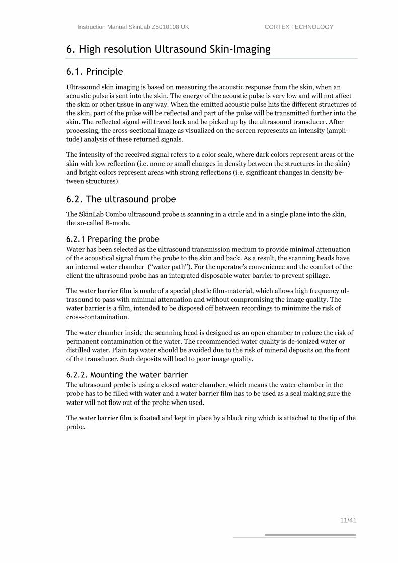
6.2.2. Mounting the water barrier
The ultrasound probe is using a closed water chamber, which means the water chamber in the
probe has to be filled with water and a water barrier film has to be used as a seal making sure the
water will not flow out of the probe when used.
The water barrier film is fixated and kept in place by a black ring which is attached to the tip of the
probe.
Instruction Manual SkinLab Z5010108 UK CORTEX TECHNOLOGY
12/41
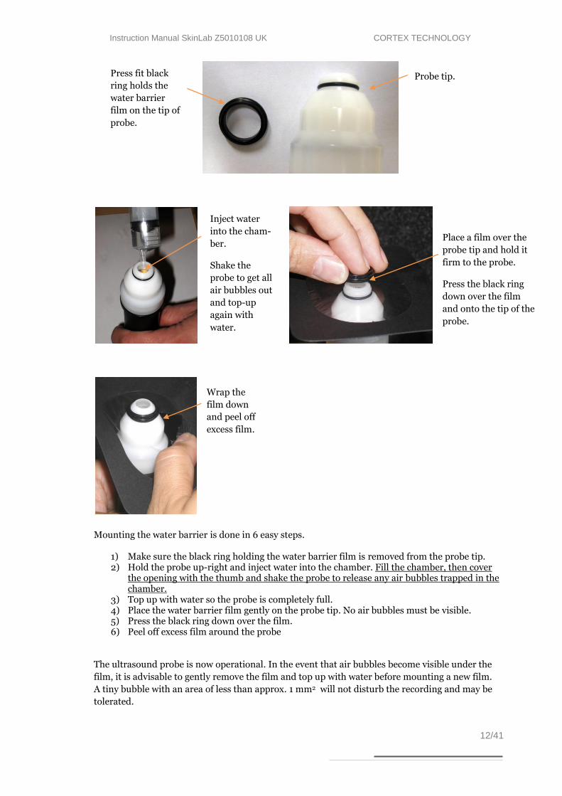
Mounting the water barrier is done in 6 easy steps.
1) Make sure the black ring holding the water barrier film is removed from the probe tip. 2) Hold the probe up-right and inject water into the chamber. Fill the chamber, then cover
the opening with the thumb and shake the probe to release any air bubbles trapped in the chamber.
3) Top up with water so the probe is completely full. 4) Place the water barrier film gently on the probe tip. No air bubbles must be visible. 5) Press the black ring down over the film. 6) Peel off excess film around the probe
The ultrasound probe is now operational. In the event that air bubbles become visible under the
film, it is advisable to gently remove the film and top up with water before mounting a new film.
A tiny bubble with an area of less than approx. 1 mm2 will not disturb the recording and may be
tolerated.
Probe tip. Press fit black
ring holds the
water barrier
film on the tip of
probe.
Wrap the
film down
and peel off
excess film.
Place a film over the
probe tip and hold it
firm to the probe.
Press the black ring
down over the film
and onto the tip of the
probe.
Inject water
into the cham-
ber.
Shake the
probe to get all
air bubbles out
and top-up
again with
water.

Instruction Manual SkinLab Z5010108 UK CORTEX TECHNOLOGY
13/41
6.2.3. Using the probe
Before each ultrasound scan apply a little drop of gel to the film. See the figure below:
Place the probe on the skin area to be scanned and spread the gel evenly to the thinnest possible
layer with “massaging” movements of the probe (see figure).
Distribute the gel evenly to a thin layer.
Alternative to the use of gel: If gel is not available then dip the tip of the probe in a cup of water.
The thin layer of water on the probe will then couple the ultrasound to the skin after placing the
probe.
6.2.4. Cleaning
After scanning, or at least after eight hours of operation, the water barrier film should be removed
disposing the water and the film and allowing the transducer to dry.
Arrange a container to collect the water coming from the probe head. The film can be peeled off
after gently pulling off the black ring.
The front piece parts can be cleaned in solutions of mild detergents suitable for plastics (Scan-
Diversey ‘‘DIVERSOL BX’’ or similar) or wiped off with alcohol for disinfection. Put the black ring
back onto the scanning head without film for storage. The water chamber inside the scanning
head can be cleaned by gently flushing with the same, mild solutions intended for use with rubber
and plastics.
Instruction Manual SkinLab Z5010108 UK CORTEX TECHNOLOGY
14/41
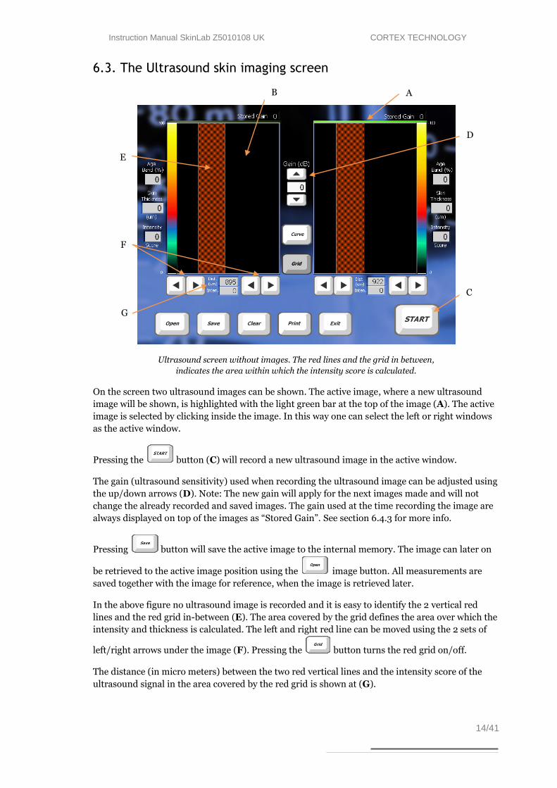
6.3. The Ultrasound skin imaging screen
Ultrasound screen without images. The red lines and the grid in between,
indicates the area within which the intensity score is calculated.
On the screen two ultrasound images can be shown. The active image, where a new ultrasound
image will be shown, is highlighted with the light green bar at the top of the image (A). The active
image is selected by clicking inside the image. In this way one can select the left or right windows
as the active window.
Pressing the button (C) will record a new ultrasound image in the active window.
The gain (ultrasound sensitivity) used when recording the ultrasound image can be adjusted using
the up/down arrows (D). Note: The new gain will apply for the next images made and will not
change the already recorded and saved images. The gain used at the time recording the image are
always displayed on top of the images as “Stored Gain”. See section 6.4.3 for more info.
Pressing button will save the active image to the internal memory. The image can later on
be retrieved to the active image position using the image button. All measurements are
saved together with the image for reference, when the image is retrieved later.
In the above figure no ultrasound image is recorded and it is easy to identify the 2 vertical red
lines and the red grid in-between (E). The area covered by the grid defines the area over which the
intensity and thickness is calculated. The left and right red line can be moved using the 2 sets of
left/right arrows under the image (F). Pressing the button turns the red grid on/off.
The distance (in micro meters) between the two red vertical lines and the intensity score of the
ultrasound signal in the area covered by the red grid is shown at (G).
E
B
C
A
F
D
G
Instruction Manual SkinLab Z5010108 UK CORTEX TECHNOLOGY
15/41
Please note: The size and position of the red-grid relative to the epidermis is defined individually
for each window. Every time a new image is recorded the left side of the red-grid is aligned to the
border between epidermis and dermis.
Please also note: The average intensity is updated every time a new ultrasound image is recorded
even if the red grid is turned off.
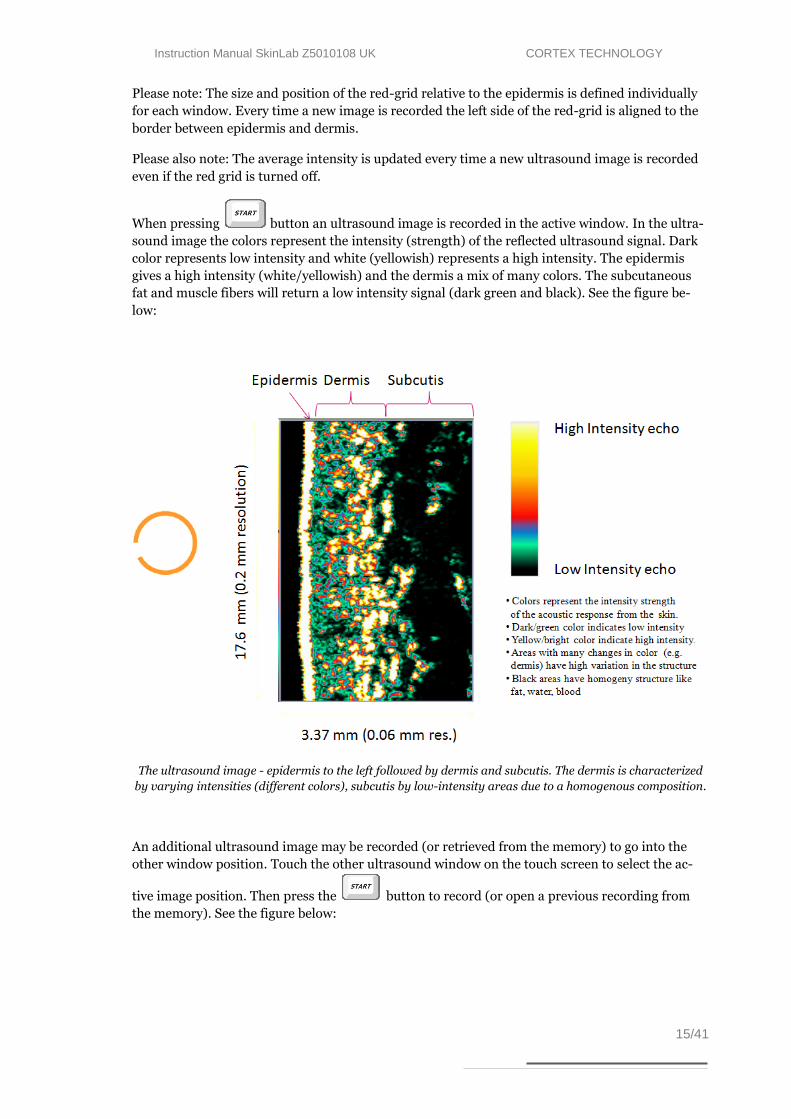
When pressing button an ultrasound image is recorded in the active window. In the ultra-
sound image the colors represent the intensity (strength) of the reflected ultrasound signal. Dark
color represents low intensity and white (yellowish) represents a high intensity. The epidermis
gives a high intensity (white/yellowish) and the dermis a mix of many colors. The subcutaneous
fat and muscle fibers will return a low intensity signal (dark green and black). See the figure be-
low:
The ultrasound image - epidermis to the left followed by dermis and subcutis. The dermis is characterized
by varying intensities (different colors), subcutis by low-intensity areas due to a homogenous composition.
An additional ultrasound image may be recorded (or retrieved from the memory) to go into the
other window position. Touch the other ultrasound window on the touch screen to select the ac-
tive image position. Then press the button to record (or open a previous recording from
the memory). See the figure below:

Instruction Manual SkinLab Z5010108 UK CORTEX TECHNOLOGY
16/41
Ultrasound screen with two images. The red lines and the grid in between,
indicate the area over which the intensity score and distance (H) is calculated.
By automatic edge detection the red grid automatically adapts to the shape of the skin surface and
follows the back side of epidermis, which is the bright line to the left in the ultrasound image.
Maintaining the skin surface curvature, the position of the right edge of the grid may be freely
adjusted with the left/right arrows (I) to for example fit the back-edge of dermis.
Note 1: As a best estimate, the edge detection algorithm assumes identical curvatures for the skin
surface and the dermis/subcut. tissue interface. Consequently, the left and right side of the skin
are identically shaped.
Note 2: The software automatically detects the edge position of epidermis and updates the red
grid position accordingly for every new image recorded (i.e. when pressing the “Start” button).
This means it is possible to automate measurements so the intensity score is always measured at
the same offset distance relative to the epidermis and with a constant width of the grid.
The red grid may be turned off by pressing the button. When turning off the red grid, the screen
will show the native ultrasound image without the grid. See the figure below:
I
H
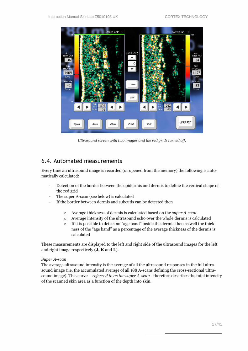
Instruction Manual SkinLab Z5010108 UK CORTEX TECHNOLOGY
17/41
Ultrasound screen with two images and the red grids turned off.
6.4. Automated measurements
Every time an ultrasound image is recorded (or opened from the memory) the following is auto-
matically calculated:
- Detection of the border between the epidermis and dermis to define the vertical shape of
the red grid
- The super A-scan (see below) is calculated
- If the border between dermis and subcutis can be detected then
o Average thickness of dermis is calculated based on the super A-scan
o Average intensity of the ultrasound echo over the whole dermis is calculated
o If it is possible to detect an “age band” inside the dermis then as well the thick-
ness of the “age band” as a percentage of the average thickness of the dermis is
calculated
These measurements are displayed to the left and right side of the ultrasound images for the left
and right image respectively (J, K and L).
Super A-scan
The average ultrasound intensity is the average of all the ultrasound responses in the full ultra-
sound image (i.e. the accumulated average of all 188 A-scans defining the cross-sectional ultra-
sound image). This curve – referred to as the super A-scan - therefore describes the total intensity
of the scanned skin area as a function of the depth into skin.

Instruction Manual SkinLab Z5010108 UK CORTEX TECHNOLOGY
18/41
When pressing the button (M) the ultrasound image is dimmed and the curve of the aver-
age ultrasound intensity - the super A-scan - is shown.
The red left part of the super A-scan shows the intensity of the ultrasound passing through the
water chamber in the probe. The high left peak originates from the combined film/epidermal re-
flection.
The red right part of the super A-scan shows the intensity of the ultrasound passing through the
subcutaneous layers.
The yellow part of the super A-scan indicates the less reflective part of the dermis (in otherwise
healthy skin a possible result of photo aging).
The green part of the curve indicates the more reflective part of the dermis (in otherwise healthy
skin a possible result of the deeper dermis being protected by the upper dermis – i.e. less photo
damage).
If the line is red all over then the aged band and/or the border between dermis and subcutis has
not been clearly detected by the software and automatic calculations are not performed.
This may be a result of incorrect (too low) gain setting. If so, then increase the gain 1-2 steps and
record a new image.
It may also be a natural consequence of a physical skin condition – e.g. edema (fluid leads to less
and weaker reflections/lower intensities).
Please note, that diseased skin may appear visually different not only to the naked eye but also in
terms of ultrasound intensity patterns and levels.
In general: homogeneous areas and tissues are less reflective and appear dark (e.g. fluid, blood,
fat, altered cell structures). Non-homogeneous structures - i.e. density changes in the media –
M
J
L
K

Instruction Manual SkinLab Z5010108 UK CORTEX TECHNOLOGY
19/41
cause reflections of varying intensities due to changing acoustical properties (e.g. healthy skin
with intact collagen, connective tissue).
6.5. The good ultrasound image
A good image delivers as much possible information in the best possible quality to the viewer in a
given situation. In other words, what is being seen on the image should be a result of tissue prop-
erties, not a result of artifacts.
The properties and composition of the human skin and subcutaneous tissues vary throughout the
body and between individuals as a result of many factors (e.g. genetics, age, sex, disease).
In the following examples will be shown to establish a common understanding of what to expect
as well as commonly seen artifacts and how to avoid them.
6.5.1. Understanding the ultrasound image
Normal ultrasound skin image
As the focused ultrasound beam propagates through the tissue, it travels through medias with
different densities. Such change in density will cause part of the ultrasound beam to be reflected,
thus generating signals to be received by the device, and part of the ultrasound beam to be trans-
mitted further into the tissue.
Tissue, which is homogeneous in structure, provides no or little density change and, accordingly,
it will generate no or few and weak reflections – it appears black. As an example blood, fat and
muscle generates only few and weak reflections. The same is true for tumor mass in general,
whereas normal skin contains a variety of structures with different densities - it appears as a visi-
ble area with varying intensities. In the above figure the individual structures of a normal forearm
image are identified.
The figures to the right show examples of
less reflective material – vein and nevus.
Subcutis
fat Epidermis
Dermis.
Normal skin over vein Intradermal nevus
Vein Nevus
Instruction Manual SkinLab Z5010108 UK CORTEX TECHNOLOGY
20/41
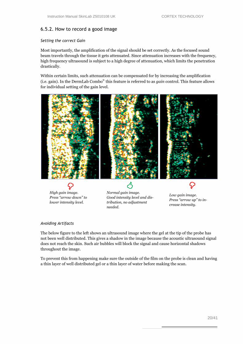
6.5.2. How to record a good image
Setting the correct Gain
Most importantly, the amplification of the signal should be set correctly. As the focused sound
beam travels through the tissue it gets attenuated. Since attenuation increases with the frequency,
high frequency ultrasound is subject to a high degree of attenuation, which limits the penetration
drastically.
Within certain limits, such attenuation can be compensated for by increasing the amplification
(i.e. gain). In the DermLab Combo this feature is referred to as gain control. This feature allows
for individual setting of the gain level.
Avoiding Artifacts
The below figure to the left shows an ultrasound image where the gel at the tip of the probe has
not been well distributed. This gives a shadow in the image because the acoustic ultrasound signal
does not reach the skin. Such air bubbles will block the signal and cause horizontal shadows
throughout the image.
To prevent this from happening make sure the outside of the film on the probe is clean and having
a thin layer of well distributed gel or a thin layer of water before making the scan.
Low gain image.
Press “arrow up” to in-
crease intensity.
Normal gain image.
Good intensity level and dis-
tribution, no adjustment
needed.
High gain image.
Press “arrow down” to
lower intensity level.
Instruction Manual SkinLab Z5010108 UK CORTEX TECHNOLOGY
21/41
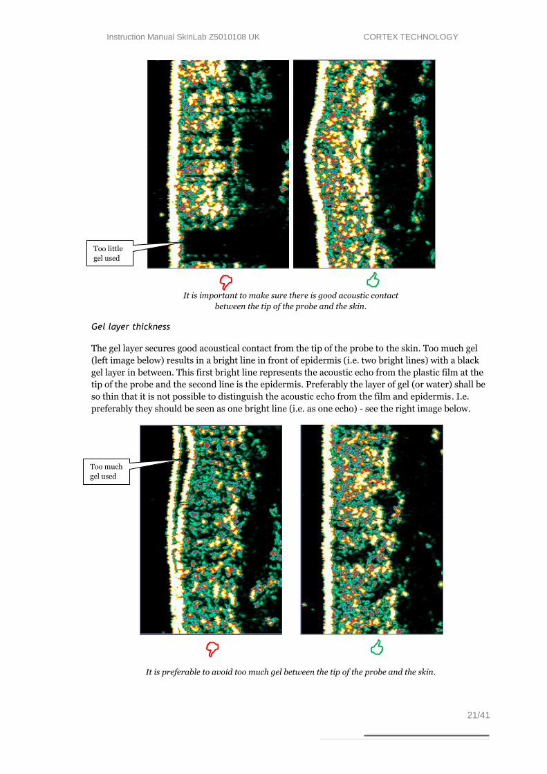
It is important to make sure there is good acoustic contact
between the tip of the probe and the skin.
Gel layer thickness
The gel layer secures good acoustical contact from the tip of the probe to the skin. Too much gel
(left image below) results in a bright line in front of epidermis (i.e. two bright lines) with a black
gel layer in between. This first bright line represents the acoustic echo from the plastic film at the
tip of the probe and the second line is the epidermis. Preferably the layer of gel (or water) shall be
so thin that it is not possible to distinguish the acoustic echo from the film and epidermis. I.e.
preferably they should be seen as one bright line (i.e. as one echo) - see the right image below.
It is preferable to avoid too much gel between the tip of the probe and the skin.
Too much
gel used
Too little
gel used

Instruction Manual SkinLab Z5010108 UK CORTEX TECHNOLOGY
22/41
6.5.3. Preparation
It may facilitate the scanning procedure to apply a drop of water or a thin layer of gel on the skin
area to be scanned. Gently distribute the water or gel in a thin layer – just enough to make the
skin wet. This will help avoiding air bubbles between the tip of the probe and the skin.
6.6. Maintenance
The daily maintenance of the ultrasound scanning probe is limited to the removal of water to re-
duce bacteria growth inside the water path and to allow the transducer to dry. Always remove the
plastic film over night.
Do not use solvents or hard objects to clean the transducer - just gently wipe off the deposits with
a cotton stick.
Instruction Manual SkinLab Z5010108 UK CORTEX TECHNOLOGY
23/41
7. Hydration (Moisture)
7.1. Principle
The SkinLab Combo Moisture Module provides information about the hydration state by measur-
ing the conducting properties of the very upper layers of the skin, when subjected to an alternating
voltage. Accordingly, the method is referred to as a conductance measurement and the output is
presented in the unit of micro-Siemens (µS).
7.2. Moisture pin-probe
The pin probe features eight contact pins and superior performance in dry skin applications, on
uneven skin surfaces and on the scalp. Further, the pins and the ventilated design reduces occlu-
sion, when applying the probe, thereby minimizing water accumulation in the skin covered by the
probe.
The probe has a spring-loaded action, which will initiate a measurement, when the probe is
pressed against the skin.
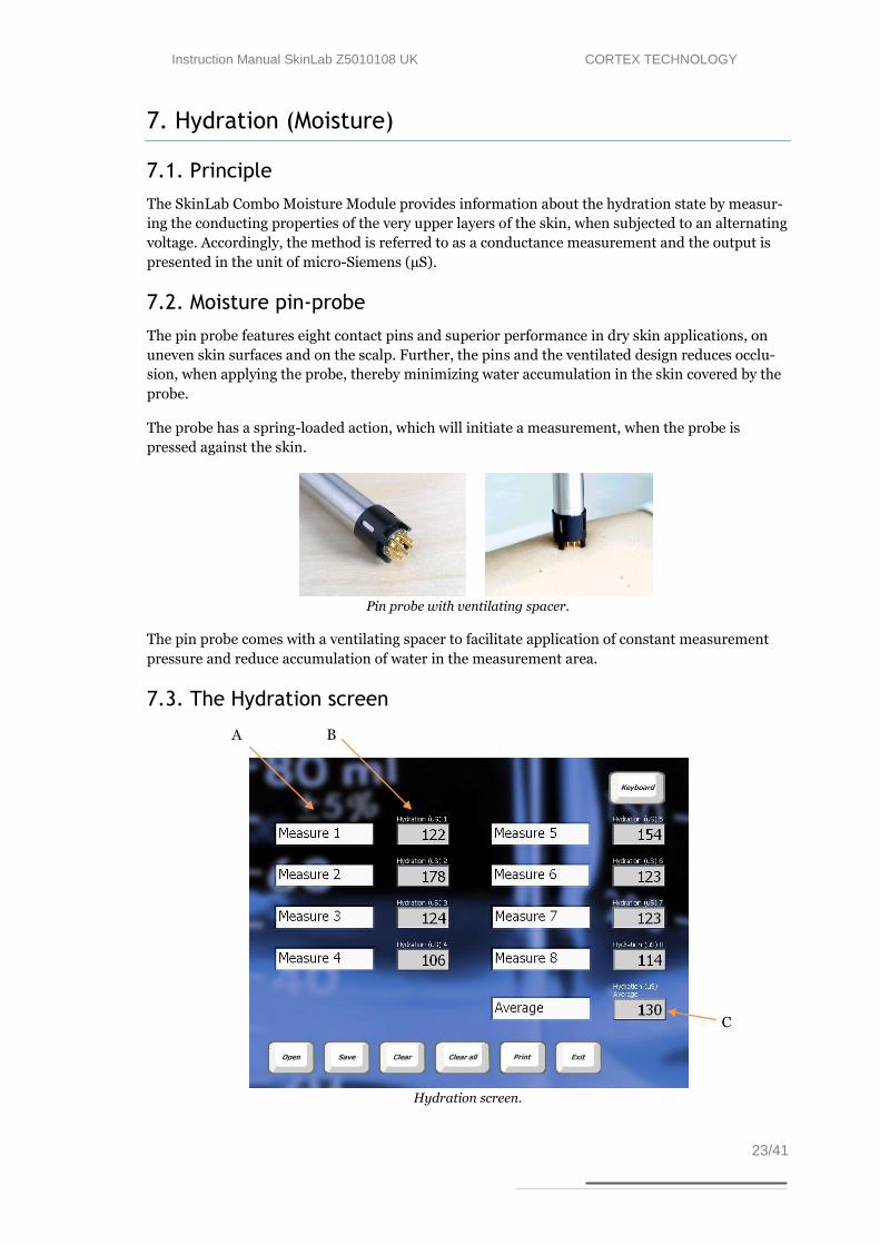
Pin probe with ventilating spacer.
The pin probe comes with a ventilating spacer to facilitate application of constant measurement
pressure and reduce accumulation of water in the measurement area.
7.3. The Hydration screen
Hydration screen.
B A
C

Instruction Manual SkinLab Z5010108 UK CORTEX TECHNOLOGY
24/41
On the hydration screen up to 8 measures of hydration can be made with the average (C)
continuously updated for each new measurement. Hydration measurements can fluctuate and in
most protocols for measuring hydration between 3 and 8 measures shall be made where after the
average is used as the final result. In the above screen 6 measures has been made.
The text fields (A) can be used to label the places on the body where the hydration measurement is
made. Press Keyboard to get access to the touch screen keyboard.
In the data field (B) the hydration measurements are shown.
The button deletes the last measurement. This is used to undo a single hydration
measurement.
The button deletes all measurements on the screen. This is used before starting a new
measurement cycle.
7.4. Maintenance
Except for keeping the probe clean there is no preventive maintenance associated with the use of
the moisture probe. To clean the probe front, simply wipe it off using a dry cloth. Should more
thorough cleaning be necessary a drop of alcohol may be applied to the cloth.

Instruction Manual SkinLab Z5010108 UK CORTEX TECHNOLOGY
25/41
8. Elasticity
8.1. Principle
The elasticity measurement of the SkinLab Combo unit is based on suction applied to the skin
surface. The probe provides a vacuum chamber and uses adhesive tape to prevent creeping and
folding of the skin under the edge surrounding the measurement chamber.
The suction method features an elevation phase and a retraction phase, the properties of which
both contribute to the “feel” of the skin. As an example, young and smooth delicate skin, which is
well moisturized, will normally be relatively easy to elevate by applying suction, and it will retract
rapidly.
Old and loose skin will also be easy to elevate, however, it will not retract rapidly. Therefore, what
is usually considered to be skin elasticity (or smoothness, softness, firmness) is of a more complex
nature and is best measured by taking both the elevation and retraction phase into account.
The SkinLab Combo offers three descriptive parameters for the skin elasticity: 1) Young´s elastic-
ity modulus (E), 2) the skin retraction time (time to retract from full extension, R) and 3) a pa-
rameter called ViscoElasticity (VE) combining both the elevation and retraction phase.
The three parameters are explained below. Which parameter(s) to choose may depend on study
design and personal preference.
1) Young´s modulus.
Calculation of Youngs elasticity modulus (E) is based on the differential force necessary to elevate
the skin surface 1.5 mm between two infrared detection levels inside the probe chamber and calcu-
lated using the following equation:
x = deviation, middle of surface
= constant
p = surface pressure
E = elasticity modulus
R = radius of the surface
S = thickness of the surface (skin thickness set to 1.00 mm)
Inserting reasonable assumptions, known probe constants and a default skin thickness of 1.00
mm leads to:
E = 0.3125
p
x
As x is 1.5 mm, the elasticity modulus E is entirely depending on the differential force needed to
elevate the skin. Young´s modulus carries the unit MPa (mega Pascal).
x = p r
E s
4
3 where :

Instruction Manual SkinLab Z5010108 UK CORTEX TECHNOLOGY
26/41
2) Retraction time.
Retraction time (R) is the time in seconds it takes for the skin to retract 1.5 mm from full eleva-
tion.
3) Visco Elasticity.
Dividing the elasticity modulus by the retraction time provides a parameter (Visco Elasticity, VE),
where both the elevation phase and the retraction phase are taken into account. R is normalized
by a retraction time of 260 ms as a typical average of underarm readings (caucasian skin, age 28 –
51).
VE = Young´s modulus/Rnormalized where Rnormalized = R/260 ms.
VE carries the unit MPa (mega Pascal).
8.2. The Elasticity Probe
Connect the probe to the input connector on the front panel (electrical connector and Luer Lock
air connector).
The use of double sided adhesive rings on the probe surfaces in contact with the skin is required to
obtain the reproducible results. First mount the adhesive ring on the probe face, then pull off the
adhesive cover before placing the probe firmly on skin. Prior to placing the probe, the skin surface
should be clean and dry for the probe to adhere.
Exchanging the adhesive ring between measurements is highly recommended.
Elasticity probe with adhesive ring.
As the suction principle applies mechanical stress to the measurement site, attention should be
paid to the fact that the measurement cannot be immediately repeated in the exact same position.
Allow 30 - 60 minutes between measurements at the same position for the skin to recover.
During the measurement, care should be taken to avoid body movement. Do not touch the probe
or pull the cables as this will influence the measurement.
Instruction Manual SkinLab Z5010108 UK CORTEX TECHNOLOGY
27/41
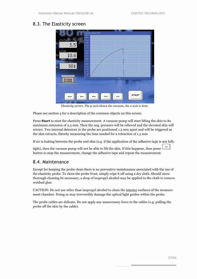
8.3. The Elasticity screen
Elasticity screen. The y-axis shows the vacuum, the x-axis is time.
Please see section 4 for a description of the common objects on this screen.
Press Start to start the elasticity measurement. A vacuum pump will start lifting the skin to its
maximum extension of 2.5 mm. Then the neg. pressure will be relieved and the elevated skin will
retract. Two internal detectors in the probe are positioned 1.5 mm apart and will be triggered as
the skin retracts, thereby measuring the time needed for a retraction of 1.5 mm
If air is leaking between the probe and skin (e.g. if the application of the adhesive tape is not fully
tight), then the vacuum pump will not be able to lift the skin. If this happens, then press
button to stop the measurement, change the adhesive tape and repeat the measurement.
8.4. Maintenance
Except for keeping the probe clean there is no preventive maintenance associated with the use of
the elasticity probe. To clean the probe front, simply wipe it off using a dry cloth. Should more
thorough cleaning be necessary, a drop of isopropyl alcohol may be applied to the cloth to remove
residual glue.
CAUTION: Do not use other than isopropyl alcohol to clean the interior surfaces of the measure-
ment chamber. Doing so may irreversibly damage the optical light guides within the probe.
The probe cables are delicate. Do not apply any unnecessary force to the cables (e.g. pulling the
probe off the skin by the cable).

Instruction Manual SkinLab Z5010108 UK CORTEX TECHNOLOGY
28/41
9. Sebum
9.1. Principle
The SkinLab Combo sebum screen provides an instrumental approach to quick and accurate
measurement of surface sebum by means of a sebum collecting device (Sebum Collector) and an
integrated reader module. Subsequent to applying the Sebum Collector to the skin, the strip is
inserted into the reader and the amount of sebum is measured based on the change in translucen-
cy of the film.
9.2. Sebum collecting strip
The sebum collecting material of the Sebum Collector is
a microporous film mounted on a light absorbing back-
ground, the color of which provides maximum absorb-
ance of the light emitted from the light source in the
reader module. Collected sebum changes the translucent
properties of the film allowing more or less light to reach
the background, where it is absorbed. Accordingly, the
amount of reflected light varies according to the amount
of sebum collected by the film.
Each Sebum Collector offers a sensitive area, and the film is mounted in a way, which greatly re-
duces wrinkling of the film, when it is inserted into the reader. The sebum collecting area is ap-
plied to the skin by pressing firmly on the backside of the area using the thumb. Press for a few
seconds, and make sure that the entire surface of the collecting area is in contact with the skin
before reinserting the Sebum Collector into the reader.
9.3. Tape Reader
The SkinLab Combo accommodates a reader module providing a slot for insertion of the strip in
use. The slot is located on the front side of the main unit (see figures below), and the strip must be
inserted with the absorbing film side (the text side) pointing down. Make sure the strip is fully
inserted into the slot by pushing it until it goes no further. A slight resistance is felt as the strip
goes in. This is intentional and a result of the strip being slightly bent in order to stretch the film
and provide a smooth surface for measuring.
To eliminate the influence of batch to batch variation of the sebum absorbing film material, an
initial offset calibration – a so-called “zero calibration” - is performed on the unexposed film prior
Sebum collecting strips.
Strip insertion. The strip fully inserted.

Instruction Manual SkinLab Z5010108 UK CORTEX TECHNOLOGY
29/41
to each skin application. Then, after application to the skin the strip is re-inserted into the slot to
measure the translucency changes of the film as a result of the absorbed sebum.
The measurement result is presented on the screen as a sebum score of saturation of the film from
0 to 99, where 99 equals very oily skin.
9.4. The Sebum screen and measurement procedure
Sebum screen.
To perform a sebum measurement proceed as follows:
1) Pick up an unused sebum collecting strip and insert it into the Tape Reader slot with the sebum colleting tape and the text side facing down. The device automatically detects the presence of the strip and performs an offset calibration before it prompts the user to per-form the next step.
2) Remove the strip and place it on the skin. Apply firm pressure and make sure that the en-tire sensitive area is in contact with the skin by “rolling” a finger over the back side of the sensitive area for a few seconds.
3) Re-insert the exposed end of the strip into the reader and wait for the reading to automat-ically appear on the screen.
In the text box (A) instructions are given for the next step in the measurement sequence
9.5. Maintenance
There is no preventive maintenance associated with the use of the SEBUM reader.
A
Instruction Manual SkinLab Z5010108 UK CORTEX TECHNOLOGY
30/41
10. Skin Color
10.1. Principle
The measurement of skin color, melanin (pigmentation) and erythema is based on an active color
detecting chip. Illumination is provided by two high intensity white LED´s.
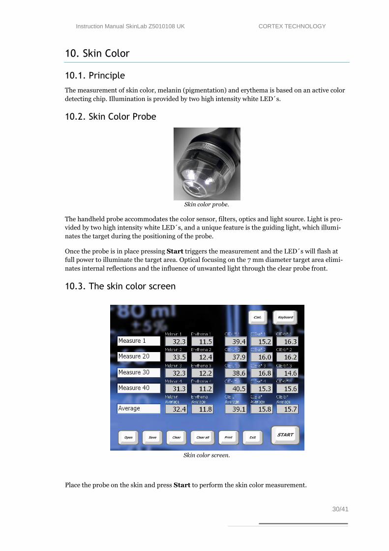
10.2. Skin Color Probe
Skin color probe.
The handheld probe accommodates the color sensor, filters, optics and light source. Light is pro-
vided by two high intensity white LED´s, and a unique feature is the guiding light, which illumi-
nates the target during the positioning of the probe.
Once the probe is in place pressing Start triggers the measurement and the LED´s will flash at
full power to illuminate the target area. Optical focusing on the 7 mm diameter target area elimi-
nates internal reflections and the influence of unwanted light through the clear probe front.
10.3. The skin color screen
Skin color screen.
Place the probe on the skin and press Start to perform the skin color measurement.
Instruction Manual SkinLab Z5010108 UK CORTEX TECHNOLOGY
31/41
Three different results are shown and the average is updated for each measurement:
Melanin is the pigmentation index of the skin. This measure is used for the estimation of level of
pigment in the skin. The higher the value the more pigment in the skin.
Erythema is the redness index of the skin. This measures is used for the estimation of the level of
redness (hemoglobin) in the skin. The higher the value the more redness in the skin.
CIE L*a*b* is the color of the skin coded in the CIELab color space. This measure is used for
measuring the color of the skin. Each measurement gives 3 values (L*, a*, b*), where L* is the
lightness of the color and (a*, b*) is a vector representing the color.
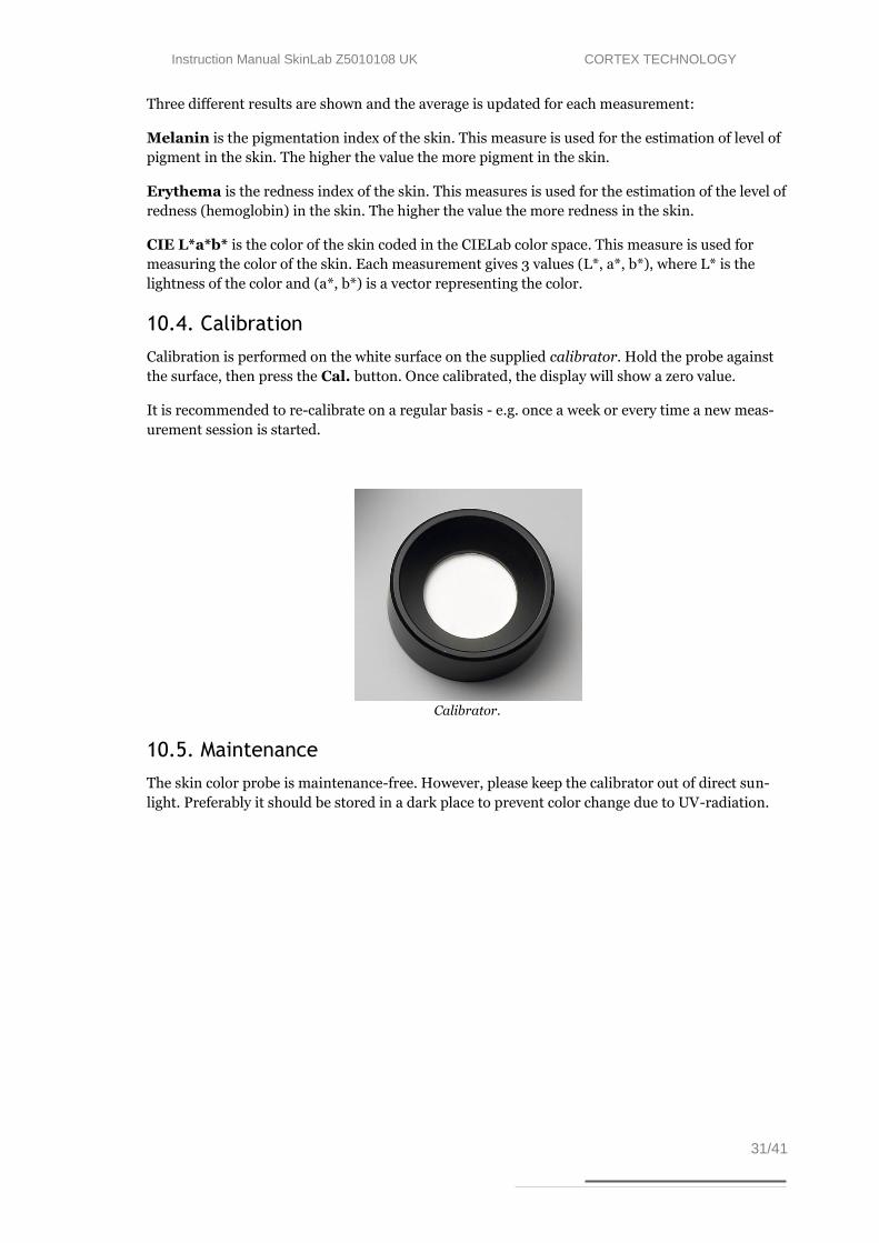
10.4. Calibration
Calibration is performed on the white surface on the supplied calibrator. Hold the probe against
the surface, then press the Cal. button. Once calibrated, the display will show a zero value.
It is recommended to re-calibrate on a regular basis - e.g. once a week or every time a new meas-
urement session is started.
Calibrator.
10.5. Maintenance
The skin color probe is maintenance-free. However, please keep the calibrator out of direct sun-
light. Preferably it should be stored in a dark place to prevent color change due to UV-radiation.
Instruction Manual SkinLab Z5010108 UK CORTEX TECHNOLOGY
32/41
11. Videoscope
11.1. Principle
The videoscope probe is able to magnify and visualize the surface of the skin using polarized or
non-polarized white light as the light source.
11.1.1. Magnification
The probe provides two focus ranges. Magnification depends on the screen size: the built-in
screen provides magnification of approx. 15x and 50x, using an external screen magnification to
approx. 200x may be obtained. The dial on the side of the probe is used to focus the image in one
of these two focus points.
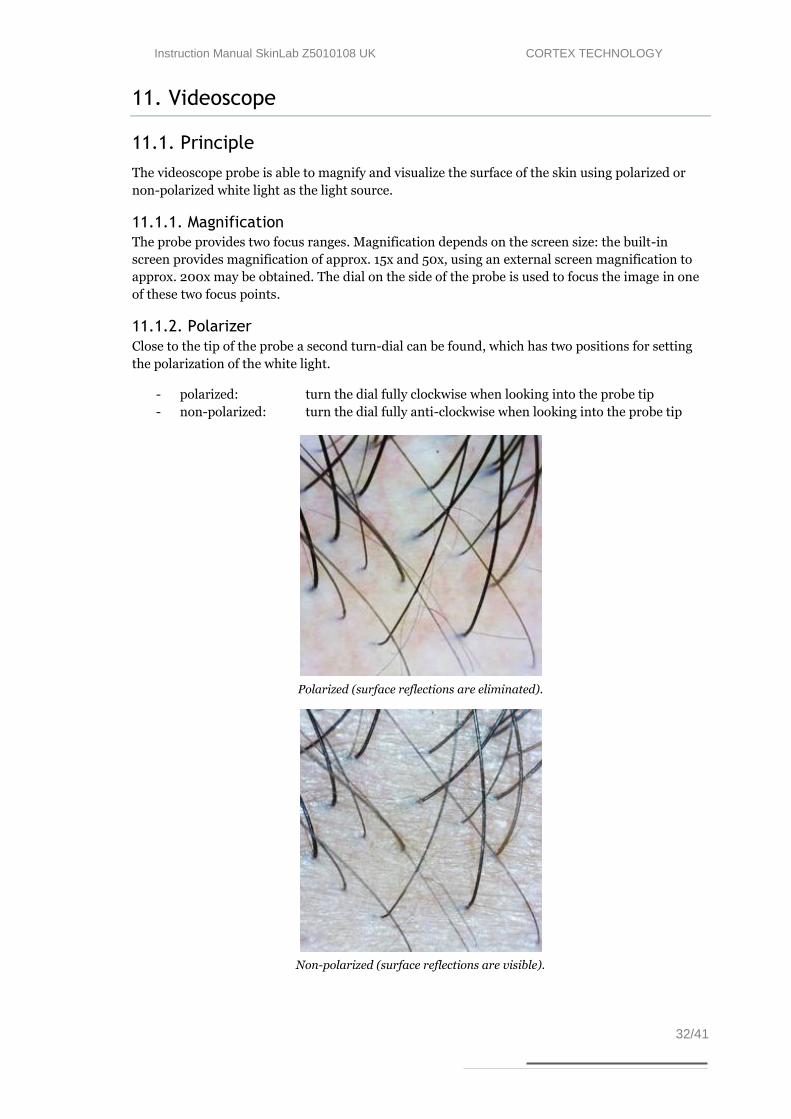
11.1.2. Polarizer
Close to the tip of the probe a second turn-dial can be found, which has two positions for setting
the polarization of the white light.
- polarized: turn the dial fully clockwise when looking into the probe tip
- non-polarized: turn the dial fully anti-clockwise when looking into the probe tip
Polarized (surface reflections are eliminated).
Non-polarized (surface reflections are visible).

Instruction Manual SkinLab Z5010108 UK CORTEX TECHNOLOGY
33/41
The polarized light setting facilitates the elimination of surface reflections similar to oil-microscopy but with-
out the need for applying oil.
It is also possible to use the videoscope for conventional oil-microscopy by mounting the clear plastic cap
supplied with the device in front of the clear plastic probe tip. Then apply oil to the skin surface and use the
non-polarized light setting.
11.2. Probe
When using the probe bring the image into focus at one of the two focus areas by adjusting the
dial on the side of the camera. Once the image is in focus at the desired magnification, take a pic-
ture by double clicking on the image on the screen or touching the small touch-button on the top
of the probe.
The captured image will then be displayed in the picture scroll list located to the left on the screen
from which any captured image may be selected for display on the main screen.
11.3. Maintenance
Except for keeping the probe clean there is no preventive maintenance associated with the use of
the videoscope probe.

Instruction Manual SkinLab Z5010108 UK CORTEX TECHNOLOGY
34/41
12. Trans Epidermal Water Loss (TEWL)
12.1. Principle
Water loss as measured by the SkinLab Combo is
based on Nilsson’s Vapor Pressure Gradient method,
an open chamber method with minimal impact on the
skin being examined and, accordingly, very low bias
to the reading.
Two sets of temperature/humidity sensors are
mounted in a measurement chamber at different
heights above the skin surface. The measurement
chamber is open to allow the skin to “breathe” freely,
and the evaporation rate follows Fick’s Law of Diffu-
sion:
Rate = P x (c1 - c2) / T
where P = permeability coefficient of membrane, (c1 - c2) = concentration gradient, T = thick-
ness of membrane.
To obtain comparable and reproducible results when measuring transepidermal water loss stand-
ardized measurement procedures are strongly recommended. Guidelines have been published by
The Standardization Group of the European Society of Contact Dermatitis :
Guidelines for transepidermal water loss (TEWL) measurement
J. Pinnagoda, R.A. Tupker, T. Agner, J. Serup
Contact Dermatitis 1990: 22: 164-178
12.2. The TEWL Probe
The probe is connected to the input connector on the front panel.
Place the probe on the skin with the perforated foam up and the open end of the measuring cham-
ber pointing towards the skin. Do not press the probe too hard against the skin - apply light to
moderate pressure.
To minimize possible cross-contamination, optional and disposable
TEWL-probe protectors are available to be placed on the open end of
the probe.
The two sensors in the probe are delicate, do not touch and handle
the probe carefully.

Instruction Manual SkinLab Z5010108 UK CORTEX TECHNOLOGY
35/41
12.3. The TEWL screen
TEWL screen, the y-axis displays the TEWL level in g/m2/h.
Pressing the button starts the TEWL measurement. On the screen the graph for the TEWL
is shown in g/m2/h as a function of time. After the TEWL has stabilized after typically 30 – 40
sec., the measurement stops automatically. In seldom cases when the line is fully horizontal the
automatic stop will not be activated. Then the measurement can be stopped by pressing the
button.
The TEWL main result is presented as the mean value over the last 5 seconds.
Tupper, Tlower RHupper, RHlower represent the individual sensor values inside the probe chamber.
These sensor values form basis for the calculation of TEWL and may provide useful diagnostic
information in case of probe malfunction r otherwise erroneous readings.
Envr. T and Envr. RH indicates the environmental conditions as measured by the probe at the
time of entering the TEWL screen.
12.4. Maintenance
Except for keeping the probe clean there is no preventive maintenance associated with the use of
the TEWL module. To clean the probe front, simply wipe it off using a dry cloth. Should more
thorough cleaning be necessary a drop of alcohol may be applied to the cloth.
The probe is delicate. Care should be taken not to touch the sensors inside the measurement
chamber.
12.5. Calibration
The sensors of the probe may, depending on the use of the probe, need re-calibration at regular
intervals. To ensure the best performance and interchangeability of your probe it is strongly
recommended to return probes for factory re-calibration regularly. By doing so, both the
humidity and temperature sensors are calibrated at probe level in a standardized setup.

Instruction Manual SkinLab Z5010108 UK CORTEX TECHNOLOGY
36/41
Re-calibration is recommended at 3-12 month intervals depending on the use of the probe - short
intervals if the probes are used extensively in very wet conditions (RH80-90%), longer intervals
at lower RH values.

Instruction Manual SkinLab Z5010108 UK CORTEX TECHNOLOGY
37/41
14. General maintenance
Maintaining the main unit is limited to cleaning the exterior of the instrument as necessary. Check
the cables and connectors regularly to ensure trouble-free operation.
Maintenance of application probes is described in the relevant application module chapter.
15. Service
Service and repair of the SkinLab Combo is only to be performed by authorized personnel or by
Cortex Technology.
However, if necessary the following spare parts may be ordered separately for replacement:
External power supply
Ultrasound probe
TEWL probe
Hydration probe
Elasticity probe
Skin-color probe
Videoscope
All probes come pre-calibrated and can be exchanged without any need for recalibrating the main
unit.
Please contact your local distributor or Cortex Technology (www.cortex.dk or [email protected])
for requests of service and repair.
15.1. Calibration of the Touch Screen
If the touch screen has drifted out of calibration (i.e. if the cursor on the screen do not exactly
show up under the point where you point), then the touch screen can be recalibrated by clicking
the “eGalaxTouch” short cut on the Windows XP desktop screen.
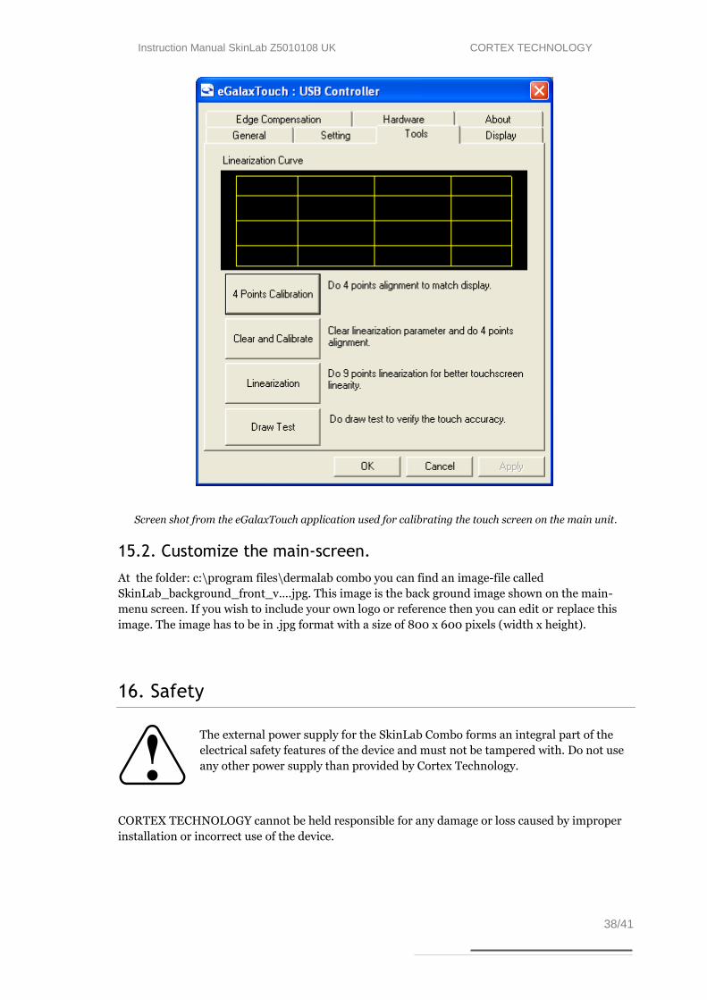
After starting the eGalaxTouch application, select “TOOLS” followed by “4-Points Calibration”
(see figure below).
A red ring will be shown in the lower-left corner of the display. Please touch the dot at the center
of the ring with the stylus. There after a red ring will be shown at the lower right corner of the
screen. Touch the center of this ring as well with the stylus and continue until all four corners have
been calibrated. Thereafter the calibration has been finished and you can exit the eGalaxTouch
application.
Instruction Manual SkinLab Z5010108 UK CORTEX TECHNOLOGY
38/41
Screen shot from the eGalaxTouch application used for calibrating the touch screen on the main unit.
15.2. Customize the main-screen.
At the folder: c:\program files\dermalab combo you can find an image-file called
SkinLab_background_front_v….jpg. This image is the back ground image shown on the main-
menu screen. If you wish to include your own logo or reference then you can edit or replace this
image. The image has to be in .jpg format with a size of 800 x 600 pixels (width x height).
16. Safety
The external power supply for the SkinLab Combo forms an integral part of the
electrical safety features of the device and must not be tampered with. Do not use
any other power supply than provided by Cortex Technology.
CORTEX TECHNOLOGY cannot be held responsible for any damage or loss caused by improper
installation or incorrect use of the device.

Instruction Manual SkinLab Z5010108 UK CORTEX TECHNOLOGY
39/41
17. Warranty
The DermaLab Series SkinLab Combo, probes and other accessories are covered by a one-year
warranty against material and manufacturing defects. Due to the nature of humidity sensors as
used in the TEWL probes and the use of these probes, re-calibration may be needed within the
one-year warranty period. Such re-calibration is not covered by the warranty.
Instruction Manual SkinLab Z5010108 UK CORTEX TECHNOLOGY
40/41
Appendix A – List of symbols
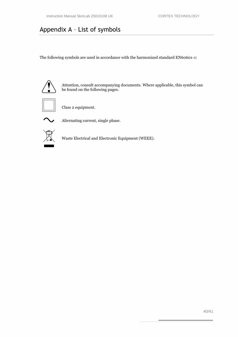
The following symbols are used in accordance with the harmonized standard EN60601-1:
Attention, consult accompanying documents. Where applicable, this symbol can be found on the following pages.
Class 2 equipment.
Alternating current, single phase.
Waste Electrical and Electronic Equipment (WEEE).

Instruction Manual SkinLab Z5010108 UK CORTEX TECHNOLOGY
41/41
Appendix B – Declaration of Conformity
EC – DECLARATION OF CONFORMITY
We hereby declare that the products listed below conform to the requirements of directive
89/336/EØF “Council Directive of 3rd May 1989 on the approximation of the laws of the
Member States relating to electromagnetic compatibility” and 73/23/EØF “Council Di-
rective of 19 February 1973 on the harmonization of the laws of Member States relating to
electrical equipment designed for use within certain voltage limits”:
DermaLab® Combo
Manufacturers name and address:
CORTEX TECHNOLOGY,
Smedevaenget 10,
9560 Hadsund,
Denmark.
Tel.: +45 9857 4100 Fax: +45 9857 2223
Implemented standards:
EN 61000-6-1
EN 61000-6-3
EN 61000-3-2
EN 61000-3-3
EN 61010-1
EN 61187
EN 50419
Place and date: Hadsund 2010/10/29 Sign.:
Gunnar Svendsen
Managing Director