deriving architectural descriptions from goal-oriented...
TRANSCRIPT
UNIVERSITE CATHOLIQUE DE LOUVAINFaculte des Sciences AppliqueesDepartement d’ingenierie informatique
Deriving architectural descriptionsfrom goal-oriented requirements
Memoire presente en vuede l’obtention du grade
Promoteur : Prof. Axel van Lamsweerde d’Ingenieur CivilCo-promoteur : Prof. Dewayne E. Perry en Informatique
parDamien Vanderveken
Louvain-la-NeuveAnnee academique 2003-2004


Abstract
Requirements and software architecture form two essential steps of the soft-ware life cycle. Although closely inter-related, most research has consideredthem to date as isolated products. On the one hand methodologies havebeen developed in order to gather complete, coherent, consistent and ade-quate requirements. On the other hand work on architecture has focused onenabling precise descriptions and on allowing formal reasoning about systemproperties such as deadlock, starvation, race conditions and so on. However,the problem of building an architecture that actually satisfies the require-ments is so far largely unaddressed. Nevertheless two methods have recentlyemerged in this direction: the KAOS method and the Preskriptor process.Both are still at an early development stage and need therefore a validationto be said effective.
This thesis validates those two approaches on a case study of significantsize (a power plant supervisory system built for ENEL, the Italian electric-ity company). It results from the analysis that both methods seem to beproductive. Indeed both resulting architectures satisfy all the functionalrequirements and most of the non-functional ones. Some weak points werealso identified among which the absence of behavioral aspects in resultingarchitecture descriptions and weak pattern descriptions.
This work extends the KAOS method by proposing the use of an archi-tecture description language to complete and precise the architectural de-scription. It results from there a set of rules and heuristics enabling to derivea structural and behavioral architecture description. In addition two pat-terns are described in details, one to achieve fault-tolerant communicationand the other to maintain data consistency. Both the resulting architecturefragment and the implied transformation process are discussed.
2

Acknowledgments
Foremost I thank my supervisor, Axel van Lamsweerde, to have introducedme to Dewayne E. Perry, so giving me the opportunity to perform a fivemonths stay in United States. Moreover I thank him for his precious feed-back, his encouragements and support all along the year.
I thank Dewayne E. Perry for his warm welcome at the University ofTexas at Austin, for his availability and his logistic support. I benefitedfrom his wise advices and from his experience.
I also wish to thank Divya Jani since part of this work was realized inclose interaction with her. It has been a pleasure to collaborate with her.
I am indebted to Christophe Ponsard for his helpful comments on earlierversions of this thesis. His suggestions significantly improved the quality ofthis work.
I also thank my two reviewers, Christophe Ponsard and Simon Brohez,for their interest about my work.
Finally, I wish to thank all my family for their every day support andmore particularly my sister. Her help was invaluable.
3


Contents
Introduction 7
1 Background 91.1 Goal-oriented Requirements Engineering . . . . . . . . . . . . 9
1.1.1 Introduction . . . . . . . . . . . . . . . . . . . . . . . 91.1.2 KAOS: A Goal-Oriented Requirement Engineering Me-
thod . . . . . . . . . . . . . . . . . . . . . . . . . . . . 101.2 Architecture Description Languages . . . . . . . . . . . . . . 18
1.2.1 Software Architecture . . . . . . . . . . . . . . . . . . 181.2.2 ADLs . . . . . . . . . . . . . . . . . . . . . . . . . . . 18
1.3 From System Goals to Software Architecture . . . . . . . . . 241.3.1 The KAOS Method . . . . . . . . . . . . . . . . . . . 241.3.2 The Preskriptor Process . . . . . . . . . . . . . . . . . 29
2 Architecture derivation for a Power Plant Supervisory Sys-tem 342.1 Informal Description of the Problem . . . . . . . . . . . . . . 342.2 Requirements Analysis . . . . . . . . . . . . . . . . . . . . . . 38
2.2.1 Requirements Elaboration . . . . . . . . . . . . . . . . 382.2.2 Obstacle Analysis . . . . . . . . . . . . . . . . . . . . 49
2.3 Architecture Derivation . . . . . . . . . . . . . . . . . . . . . 562.3.1 Using the KAOS Method . . . . . . . . . . . . . . . . 562.3.2 Using the Preskriptor Process . . . . . . . . . . . . . . 612.3.3 Comparing the Resulting Architectures . . . . . . . . 68
2.4 Discussion . . . . . . . . . . . . . . . . . . . . . . . . . . . . . 712.4.1 Evaluating the Methods . . . . . . . . . . . . . . . . . 712.4.2 Opportunities for Improvements . . . . . . . . . . . . 752.4.3 Comparing the Methods . . . . . . . . . . . . . . . . . 76
5

CONTENTS 6
3 Toward More Precise Architecture Derivation 783.1 Wright . . . . . . . . . . . . . . . . . . . . . . . . . . . . . . . 793.2 Deriving Architectures in Wright . . . . . . . . . . . . . . . . 81
3.2.1 Integration within the KAOS method . . . . . . . . . 813.2.2 Structure . . . . . . . . . . . . . . . . . . . . . . . . . 823.2.3 Behavior . . . . . . . . . . . . . . . . . . . . . . . . . . 843.2.4 Elaboration of Scenarios . . . . . . . . . . . . . . . . . 95
3.3 Application to the Power Plant System . . . . . . . . . . . . 963.4 Making Architectural Patterns Further Precise . . . . . . . . 103
3.4.1 The Fault-Tolerant Communication Pattern . . . . . . 1033.4.2 The Observer Pattern . . . . . . . . . . . . . . . . . . 113
3.5 Discussion . . . . . . . . . . . . . . . . . . . . . . . . . . . . . 119
Conclusion 121
Bibliography 124
List of Figures 128
List of Tables 130
A KAOS Specifications 131A.1 Goal specifications . . . . . . . . . . . . . . . . . . . . . . . . 131
A.1.1 Functional goals . . . . . . . . . . . . . . . . . . . . . 131A.1.2 Non-functional goals . . . . . . . . . . . . . . . . . . . 142
A.2 Object Specifications . . . . . . . . . . . . . . . . . . . . . . . 143A.3 Agents Specifications . . . . . . . . . . . . . . . . . . . . . . . 149A.4 Operations specifications . . . . . . . . . . . . . . . . . . . . . 154A.5 Modifications resulting from the obstacle analysis . . . . . . . 162
B Architectural Prescriptions 165B.1 Initial Prescriptions . . . . . . . . . . . . . . . . . . . . . . . 165B.2 Prescriptions resulting from step 4 . . . . . . . . . . . . . . . 169
C Wright Specifications 172C.1 The Fault-Tolerant Communication Pattern . . . . . . . . . . 172
C.1.1 Initial Wright Specification . . . . . . . . . . . . . . . 172C.1.2 Resulting Wright Specification . . . . . . . . . . . . . 173
C.2 The Observer Pattern . . . . . . . . . . . . . . . . . . . . . . 176C.2.1 Initial Wright Specification . . . . . . . . . . . . . . . 176C.2.2 Resulting Wright Specification . . . . . . . . . . . . . 177

Introduction
Requirements and software architecture have long been recognized as twocrucial parts of the software development process. Inadequate, inconsistent,incomplete or ambiguous requirements have a critical impact on the qual-ity of the resulting software. So does software architecture. Its influenceis particularly significant on non-functional properties such as performance,reliability, and security. Since ten years, the scientific community has there-fore focused its efforts on the development of methods and tools so as toimprove practices in those two areas. Therefrom goal-oriented requirementengineering and architectural description languages (ADL) have emerged asthe most satisfactory solutions.
Far from being independent, requirements and architecture are closelyinter-related. Requirements should serve as the basis to the architecturedesign while architecture must satisfy requirements. However, research hasonly recently considered the problem of building an architecture that satisfiesthe requirements.
The KAOS method and the Preskriptor process are two different ap-proaches toward this direction. They both use goal-oriented requirementsexpressed in linear temporal logic using the KAOS framework in order tobuild an architecture satisfying functional and non-functional requirements.The KAOS method starts by deriving an abstract dataflow architecture inwhich all functional goals hold. It refines it further by applying styles andpatterns in order to achieve architectural constraints and non-functionalgoals respectively. The Preskriptor process constructs an architectural pre-scription of the system. A component refinement tree is elicited from re-quirements so that each goal is ensured by a component.
However these two methodologies are still at an early development stage.They lack of a validation on real examples to prove their efficiency. The aimof this work is twofold; it is first to evaluate and compare both methodsby applying them on a system of reasonable size and secondly to improve amethod on the basis of weak points identified during the methods applica-
7

INTRODUCTION 8
tion.The case study deals with a power plant supervisory system developed
for ENEL, the Italian electricity company. System description was extractedfrom various papers reporting this industrial experience. Therefrom therequirements specifications needed as starting point for both architecturederivation techniques were extracted. The KAOS method and the Preskrip-tor process were then applied to derive the software architecture.
The main result which has emerged from the experiment analysis wasthe two methods seem to be effective. Indeed both resulting architecturesensure all functional and most of the non-functional requirements.
Those methodologies were nevertheless not perfect. The absence of be-havioral description in the resulting architectures was identified as their maincommon weakness. Moreover patterns descriptions were also insufficient inthe KAOS method.
An Architectural Description Language (ADL) was used to improve theKAOS method with respect to the identified problems. It results from therea set of rules and heuristics enabling to derive a structural and behavioralarchitecture description as well as a precise description of two patterns,one to achieve fault-tolerant communication and the other to maintain dataconsistency.
This thesis is structured as follows: Chapter 1 provides the necessarybackground material, Chapter 2 describes the case study and Chapter 3 ex-plores the use of an ADL in order to add a behavioral aspect to architecturedescription and defines precisely two patterns. Finally the conclusion sum-marizes the main points of this work and presents some further work. Theappendices include complete specifications of the requirements and of thederived architecture for the power plant supervisory system.
Chapter 1
Background
1.1 Goal-oriented Requirements Engineering
1.1.1 Introduction
Before being able to construct any system, it has first to be understood.Requirements of the envisioned system have to be defined. Its objectivestogether with the needs they fulfill state why the system is needed. Itsfeatures, be they functional or non-functional, state what the system hasto do. Functional aspects consist of the services to be provided while non-functional ones deal with the quality of the developed software. They en-compass safety, security, usability, flexibility, performance, robustness, in-teroperability, cost, maintainability, and so on. The way those requirementswill be met state how the system will be built. Precise requirements shouldanswer the WHY/WHAT/HOW questions.
Requirement engineering is concerned with the elaboration of such re-quirements. Goals to be achieved have to be identified then operationalizedinto services and constraints. The responsibility of achieving those two mustnext be assigned to some agents, be they part of the environment (e.g., hu-man or devices) or of the software itself. One should note that requirementsare not fixed once and for all. They need continuous review and revision.So requirement engineering is an iterative process
Requirement engineering is recognized as a stage of prime importance inthe software development process. Inadequate, inconsistent, incomplete orambiguous requirements have a critical impact on the quality of the resultingsoftware. Studies have shown that a requirement error corrected at a latedevelopment phase could cost up to 200 times more than if it had beencorrected during the requirement engineering phase. Poor requirements are
9
CHAPTER 1. BACKGROUND 10
also a major cause of software failure according to the managers in chargeof the project. By software failure, it is meant a project that was nevercompleted or only partially.
Goals are an essential component in the requirement engineering process.They provide the rationale of the system answering the WHY question.Object-oriented analysis techniques do not address such concerns. This hasled to a migration from an object orientation to a goal orientation.
Goal-oriented requirement engineering encompasses a set of techniquesincluding goal modeling, goal specification, and goal-oriented reasoning.Two complementary approaches have emerged into two different frame-works: a formal and a qualitative one.
The formal framework assigns linear temporal logic formulas to goalsand uses AND/OR refinements to structure them. Roughly, when a goal isAND-refined into subgoals it means that the satisfaction of all of its subgoalsis a sufficient condition to satisfy this goal. Similarly, when a goal is OR-refined it means that the satisfaction of one of its subgoals is a sufficientcondition to satisfy the goal.
In the qualitative framework, weaker versions of those links are intro-duced to relate ”soft” goals. The links express contribution, be it positiveor negative, from a goal to another. ”Soft” goals denote goals whose satis-faction is difficult to check in a clear-cut sense. The concept of satisficingis introduced to express that some goal is achieved within acceptable limits,rather than absolutely. If a goal is AND-decomposed into subgoals and allsubgoals are satisficed, assuming all the subgoals contribute positively, thenthe goal is satisficeable; but if a subgoal is denied then the goal is deniable.
1.1.2 KAOS: A Goal-Oriented Requirement Engineering Me-thod
The formal framework gave rise to the KAOS methodology for eliciting,specifying and analyzing goals, requirements, scenarios, and responsibilityassignments. This is the methodology used to elaborate the requirements ofthe power plant supervisory system.
Four complementary and interdependent models form the requirementsin the KAOS method: (1) the goal model, (2) the object model, (3) the agentmodel and (4) the operation model. Each of them presents a different view ofthe system and consists of a graphical and a textual representation. KAOShas a two-level semantic. A semantic net layer captures goals, constraints,agents, objects and actions together with their link while the formal assertionlayer uses real-time first order linear temporal logic [22] to support formal

CHAPTER 1. BACKGROUND 11
specification and reasoning.The goal model presents an intentional view of the studied system. Func-
tional and non-functional goals are structured by AND/OR goal diagrams.Higher level goals are rather general and involve multiple agents while lowerlevels are more technical and involve less agents. Goals belong to variouscategories (e.g., Security, Information), can be of different types (e.g., Main-tain/Avoid, Achieve/Cease) and are characterized by attributes (e.g., Name,Definition). Terminal goals are distinguished according to the agent theyare assigned to. A requirement is a terminal goal assigned to an agent of thesoftware-to-be while an expectation is a terminal goal assigned to an agentpart of the environment. The latter cannot be enforced by the software-to-be. The refinement ends up when each leaf goal is realizable by a singleagent.
The object model provides a structural view. Domain objects of interestare modeled by UML class diagrams. Objects can be entities, associations,events or agents and are characterized by attributes and invariants. In-variants can be domain properties, that is, properties about object of theenvironment that hold independently of the software-to-be. Objects reflectthe state of the system at a certain point in time.
The agent model points out the responsibilities in the system. Agentsare active components that play some role toward goal satisfaction. Theycan be either part of the software or part of the environment (e.g., humans,sensors, actuators). Goals under the responsibility of software agents arerequirements while those under the responsibility of environment agentsare expectations. Their capabilities in terms of monitored and controlledvariables are expressed through context diagrams.
The operation model reveals the behavior of the system. Operationsexpress state transitions over objects of the system. An operation is specifiedby the classic pre/postcondition mechanism. A distinction is though madebetween domain pre/post conditions and pre-, post- and trigger conditionsrequired for the satisfaction of some goal. The dynamic can be expressedgraphically using scenarios and state charts.
These four models are strongly interwoven. The definition of goals refersto objects. Agents perform operations that operationalize goals, i.e., ensuregoal satisfaction. The interface of agents refers to object definition. Opera-tion application defines a state transition of some object. The links betweenmodels ensure a coherent, consistent, complete, and adequate picture of thesystem is constructed.
Now that basic underlying concepts have been exposed, the KAOS me-thodology itself will be illustrated with simplified excerpts of requirements
CHAPTER 1. BACKGROUND 12
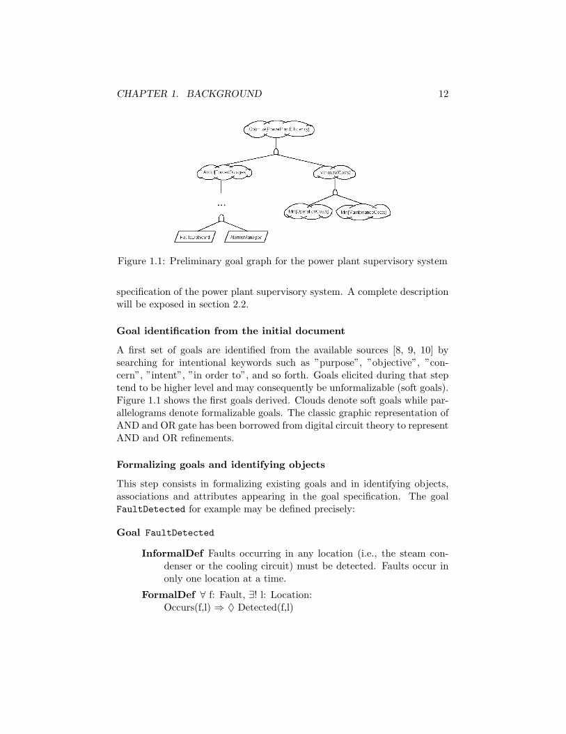
Figure 1.1: Preliminary goal graph for the power plant supervisory system
specification of the power plant supervisory system. A complete descriptionwill be exposed in section 2.2.
Goal identification from the initial document
A first set of goals are identified from the available sources [8, 9, 10] bysearching for intentional keywords such as ”purpose”, ”objective”, ”con-cern”, ”intent”, ”in order to”, and so forth. Goals elicited during that steptend to be higher level and may consequently be unformalizable (soft goals).Figure 1.1 shows the first goals derived. Clouds denote soft goals while par-allelograms denote formalizable goals. The classic graphic representation ofAND and OR gate has been borrowed from digital circuit theory to representAND and OR refinements.
Formalizing goals and identifying objects
This step consists in formalizing existing goals and in identifying objects,associations and attributes appearing in the goal specification. The goalFaultDetected for example may be defined precisely:
Goal FaultDetected
InformalDef Faults occurring in any location (i.e., the steam con-denser or the cooling circuit) must be detected. Faults occur inonly one location at a time.
FormalDef ∀ f: Fault, ∃! l: Location:Occurs(f,l) ⇒ ♦ Detected(f,l)

CHAPTER 1. BACKGROUND 13
From the definition of that goal, several objects and relationships can beidentified. The resulting portion of the object model is presented in Figure1.2.
Figure 1.2: First draft of the object model
The goal AlarmManaged is hardly formalizable but an informal definitioncan nonetheless be given.
Goal AlarmManaged
InformalDef The system must raise an alarm each time a fault isdetected. In addition, it must trace and keep the state of allalarms previously raised.
The model previously built can now be enriched with the new conceptsadded by this definition (see Figure 1.3.
Figure 1.3: Second draft of the object model
Eliciting new goals through WHY questions
Finding more abstract goals, besides completing the goal diagram, can pointout some subgoals missing in the first description. A lot of goals are often
CHAPTER 1. BACKGROUND 14
implicit in the available sources and may be discovered as a by-product ofthe abstraction mechanism.
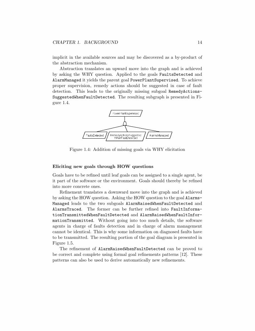
Abstraction translates an upward move into the graph and is achievedby asking the WHY question. Applied to the goals FaultsDetected andAlarmManaged it yields the parent goal PowerPlantSupervised. To achieveproper supervision, remedy actions should be suggested in case of faultdetection. This leads to the originally missing subgoal RemedyActions-SuggestedWhenFaultDetected. The resulting subgraph is presented in Fi-gure 1.4.
Figure 1.4: Addition of missing goals via WHY elicitation
Eliciting new goals through HOW questions
Goals have to be refined until leaf goals can be assigned to a single agent, beit part of the software or the environment. Goals should thereby be refinedinto more concrete ones.
Refinement translates a downward move into the graph and is achievedby asking the HOW question. Asking the HOW question to the goal Alarms-Managed leads to the two subgoals AlarmRaisedWhenFaultDetected andAlarmsTraced. The former can be further refined into FaultInforma-tionTransmittedWhenFaultDetected and AlarmRaisedWhenFaultInfor-mationTransmitted. Without going into too much details, the softwareagents in charge of faults detection and in charge of alarm managementcannot be identical. This is why some information on diagnosed faults haveto be transmitted. The resulting portion of the goal diagram is presented inFigure 1.5.
The refinement of AlarmRaisedWhenFaultDetected can be proved tobe correct and complete using formal goal refinements patterns [12]. Thesepatterns can also be used to derive automatically new refinements.

CHAPTER 1. BACKGROUND 15
Figure 1.5: Addition of missing subgoals via HOW elicitation
Identifying potential responsibility assignments
During this step, terminal goals are examined and agents having the ca-pabilities to take the responsibility of those goals are identified. Multipleagents can be able to achieve some goals. The goal AlarmRaisedWhenFault-InformationTransmitted could be assigned either to some automated (i.e.,software or hardware) components or to a power plant employee. The formerwould raise the alarm automatically while the later would do it manually.The situation is presented in Figure 1.6.
Figure 1.6: Potential agents
A qualitative reasoning can drive the selection among alternatives. Inthis case, assigning the goal to a power plant employee would contributenegatively to the soft goal Minimize[OperationCosts]. The software agentshould therefore be preferred.
CHAPTER 1. BACKGROUND 16
Deriving agent interfaces
Let assume that the goal AlarmRaisedWhenFaultInformationTransmittedhas been assigned to a software component, namely ALARM. Its interface interms of monitored and controlled variables can be derived from the formalspecification of this goal:
Goal AlarmRaisedWhenFaultInformationTransmitted
FormalDef ∀ fi: FaultInformation, ∃! a: alarmTransmitted(fi,PRECON,ALARM) ⇒ ♦ Raise(fi,a)
Note that FaultInformation is the software representation of the faultconcept and that PRECON is the agent in charge of fault detection. ALARMneeds consequently to be able to monitor FaultInformation and controlsAlarm. Similar reasoning can be applied to other agents to derive theirinterface.
Identifying operation
For each goal, an operation is identified and preliminary defined by pre- andpostconditions resulting from the domain. For the goal AlarmRaisedWhen-FaultInformationTransmitted defined previously, the following operationcan be defined:
Operation RaiseAlarm
Input fi: FaultInformation, a: AlarmOutput a: AlarmDomPre ¬Raise(fi,a)DomPost Raise(fi,a)
This operation definition only defines the basic state transition but doesnot ensure the goal.
Operationalizing goals
Once identified, operations have to be straighten in order to ensure the goalthey operationalize. Required pre-, post- and trigger conditions are addedto operations specification to ensure the satisfaction of goals. Operational-ization can be automated using operationalization patterns [20]. In order toensure the goal AlarmRaisedWhenFaultInformationTransmitted the spec-ification of RaiseAlarm has to be modified:

CHAPTER 1. BACKGROUND 17
Operation RaiseAlarm
Input fi: FaultInformation
Output a: Alarm
DomPre ¬Raise(fi,a)
DomPost Raise(fi,a)
ReqTrig for AlarmRaisedWhenFaultInformationTransmitted@ Transmitted(fi,PRECON,ALARM)
The trigger condition states that when the trigger condition becomestrue and if the preconditions hold then the operation must be applied.
The introduced KAOS methodology provides a set of both formal andsemi-formal techniques enabling to build requirements. One should notethat the method has been explained as being sequential but it was only fora presentation purpose. Far from the waterfall model, the KAOS methodconsiders requirement elaboration as an iterative process.
In order to keep things concise, neither conflicts that can arise betweengoals nor obstacles to goal satisfaction have been addressed. However, theseconcerns are included in the method. More information on conflict manage-ment can be found in [28] and on obstacles handling in [29].

CHAPTER 1. BACKGROUND 18
1.2 Architecture Description Languages
1.2.1 Software Architecture
Software architecture is concerned with the organization of software. It con-sists of a description of constituent architectural elements, their interactionsand the constraints on those elements. Elements are divided into two cate-gories: components and connectors. Components are used to denote pointsof computations while connectors define the interactions between these com-ponents. Interactions include communication and synchronization protocolswhich set up a coordination scheme between components. Typical con-straints include security, performance or conformance to a particular style(e.g, pipes and filters, client-server, event-based).
Architecture can be viewed as a bridge between requirements and codeand should thereby provide a framework in which to satisfy the requirementsand serve as a basis for the design [24]. Architecture is besides known to havea major impact on non-functional requirements like performance, security,maintainability, interoperability.
When specifying an architecture, whatsoever be the mean used, somecharacteristics are desirable for the resulting description:
• Different aspects of the architecture have to be expressed in an appro-priate manner. Aspects encompass structure (i.e., the way the differentcomponents and connectors are interconnected, the system topology),behavior (i.e., the abstract behavior of each component, the protocolsof interactions they use to communicate and coordinate their effort inorder to achieve some global behavior) and style (i.e., belonging to aparticular style with its associated properties and constraints).
• Architecture descriptions should allow some form of reasoning to checkwhether or not some key system properties such as performance, reli-ability or security are satisfied and to what extent. In distributed en-vironments, classical issues like presence of deadlock, starvation, raceconditions should be addressed.
1.2.2 ADLs
Architectural description languages (ADL) are an attempt in this direction.They set up means enabling to describe and analyze architecture in a verymuch satisfactory way compared to traditional ”box-and-line” architecturedescriptions. Various formalisms allow precise specifications and formal rea-soning. Their use is often supported by tools for displaying, compiling,
CHAPTER 1. BACKGROUND 19
analyzing or simulating architectural descriptions. Lots of ADL have beendesigned over the last decade and they differ greatly by the intent pur-sued, the formalism used and the capabilities offered. Three representativeADLs[16] – C2 [23], Darwin [21, 18] and Wright [2, 1] – will be examinedin details, looking for similarities and differences. Their capabilities withrespect to the criteria stated above will be checked.
Although very different in the capabilities offered ADLs nonethelessshare a set of primitive concepts that form the basis for any architecturedescription [16]. The main elements are:
• Components represent the primary computational and data stores ofa system. Components often have interfaces describing any point ofinteraction between the component and its environment.
• Connectors represent interactions between components. They coordi-nate the linked components and are therefore often called the ”glue”of the system.
• Systems are configurations of components and connectors. They cap-ture the overall topology of the system. Some ADLs also provide hier-archical constructs, enabling some subsystems with their own internalstructure to be described in terms of a new architecture.
• Properties express semantic information about a system and its com-ponents that goes beyond structure. For example, some ADLs allow toestimate the overall performance of a system expressed by a its latencytime and throughput.
• Constraints prescribe claims about an architectural design that shouldremain true even if it evolves over time. One could imagine for exam-ple to constrain the topology of the system in such a way that allcomponents are linked through binary connectors.
• Styles describe families of related systems. A style is typically de-scribed by a design vocabulary (i.e., the types of components and con-nectors), a composition rule (i.e., describing the allowable structure)and by invariants (i.e., properties that hold in any instantiation of thestyle) [26]. Typical examples of style include pipes and filters, layeredsystems, blackboard systems and client-server systems.

CHAPTER 1. BACKGROUND 20
Comparative study
Now that the common basis has been provided, three considered ADLs arefurther described. In a first time it is important to introduce them andto reveal their aim. C2 is a component- and message-based style used tosupport the particular needs of applications that have a graphical user in-terface aspect. Darwin aims at modeling and analyzing distributed systems.Wright focuses on formal specifications and analysis of interactions betweenarchitectural components.
Modeling capabilities First ADL ability to model different aspects ofarchitecture – structure, behavior and styles – is inspected.
Structure With respect to the structure description, the three ADLstake different approaches. C2 structures components into layers. Each com-ponent has a top and a bottom domain used to define the interface with theupper and the lower layer respectively. Layers are structured by level of ab-straction, each layer n using services of component belonging to layer n− 1.The principle of limited visibility holds between layers, that is, componentsof layer n are only aware of components belonging to layer n−1. In Darwin, asystem consists of components linked through connectors. Each componentdefines a set of services provided and required. Connectors link services,one end provides the service the other end requires. A textual and a graphi-cal representation support are used. Darwin allows composites components,that is, components that are constructed from basic or composite elements.So it enables to describe the system hierarchically. Wright distinguishescomponents and connectors as basic primitives. Each component defines itsexternal interface by a set of ports, each one representing a particular pointof interaction with the environment. Connectors are characterized by roles.Roles describe the expected behavior of the interacting parties. Connec-tors are then used to link components whose ports are compatible with theroles of the connectors. As in Darwin, hierarchical structures are supported.Structural aspects are handled in a more general manner in Darwin andWright while the way C2 addresses structure reflects the intended audience.Actually, applications having a graphical user interface often decouple thepresentation layer from the computation layer.
Behavior Behavior is as important as structure to describe architec-tures since it provides a mean to check whether the system will actually dowhat it is expected to. Surprisingly, the behavioral view is missing from
CHAPTER 1. BACKGROUND 21
C2. Although not present in the early days, Darwin now supports behaviordescription of components using a finite process algebra (FSP). In Wright,the behavioral view is fundamental. As in Darwin, a process algebra isused, namely CSP in this case. Behavior of components and connectorscan be specified. Each component possesses a computation field describingits global behavior and the ports describe its behavior at that particularpoint of interaction. Similarly connectors roles indicate the local expectedbehavior of the interacting parties while the glue field specifies how the ac-tivities of the different roles are coordinated. Compared to Darwin, Wrightputs emphasis on connectors, adding a degree of freedom in the behavioraldescription while Darwin considers connectors as link elements without anyrole in the coordination of components.
Styles The increasingly recognized importance of styles in the softwarearchitecture field has made the ability to define a style in a ADL a “must”.Once again C2 does not support styles description. This is not strictly truesince every architecture description in C2 follows implicitly a layered styleand no emphasis is put on the resulting invariant of this style. Darwin doesneither provide any constructs supporting style definitions. Only Wrightreally supports it. A style definition in Wright consists of descriptions ofcomponents and/or connectors, interface types and constraints. Componentand connector can be parametrized in order to enable specialization for ap-plication purposes. Interface types, opposed to components and connectors,only constrain part of a component or connector. Constraints express prop-erties that every style instantiation must obey. Such constraints includefor example topological issues. Wright is here the only one that providessatisfactory style support.
Reasoning capabilities After evaluating the ADLs with respect to theirabilities to express the different aspects of an architecture it is tried toexamine the various forms of reasoning supported. It represents a movefrom a modeling point of view toward an analysis point of view.
C2 does support some analysis but not at the architectural level, strictlyspeaking. Type checking mechanisms are used to check whether a concretecomponent can be used as an implementation of an architectural componentor whether a concrete component may substitute to another. Darwin pro-vides both structural and behavioral checks. A configuration can be checkedto see whether services provided and required by linked components arecompatible. The behavior can be analyzed through the Labeled Transition
CHAPTER 1. BACKGROUND 22
Analyzer (LTSA) tool. It enables to visualize execution traces and to checksafety1 and progress2 properties. Similar checks are performed in Wright.The ports of components are compared to the roles of connectors to checkwhether they are behaviorally compatible. The analysis tools available forCSP – ProBE and FDR – can be used on Wright descriptions. ProBE[14] isan animator used to visualize potential executions while FDR[13] is a modelchecker enabling for example to check the presence of deadlock, starvationand race conditions. The level at which C2 performs its analysis deals withthe dependencies between architecture and code phases. Darwin and Wrightconcentrate their analysis to the architectural level checking both structureand behavior.
Tool support The three presented ADLs are supported by tools. Thesetools belong to three categories:
1. Design Assistants: these tools focus on providing a graphical front endto allow architects to develop designs.
2. Design Checkers: they provide various analysis properties
3. Code Generators: they enable to generate code from the architecturaldescription
C2 is supported by a design assistant and by a code generator. Thecode generator provides partial implementation that forms a developmentframework. Darwin has a development environment and as previously saiddesign checkers. Wright only possesses design checkers.
Conclusion The evaluation of the three considered ADLs is summarizedin Table 1.1. The results obtained bring the following conclusions. Wright isthe more powerful. It is the only one to describe the three architectural as-pects – structure, behavior and style and the analysis supported covers boththe structural and the behavioral part of the architecture. Darwin is lesscomplete in the architecture behavior description since no account is made ofconnectors. Moreover styles are not addressed. C2 seems more limited bothin the description of the architecture and in the analysis provided. Nonethe-less it points out an important fact: with the central position of architecturein the software engineering process between requirements and code, ADLs
1a safety property refers to a property that holds over all executions2the progress property states that the program will eventually reach the desired state
(it implies for example that the program never enters an infinite loop)

CHAPTER 1. BACKGROUND 23
ADL Structure Behavior Style Reasoning toolsC2 layered no no implementation design assistant
systems conformance code generatorDarwin all systems components yes structure design assistant
behavior design checkerWright all systems components yes structure design checker
connectors behavior
Table 1.1: Comparison between C2, Darwin and Wright
should provide some means to check that requirements are satisfied and thecode complies with the architecture. Moreover none of the ADLs studiedare able to perform analysis concerning critical non-functional propertiessuch as performance, reliability, fault tolerance, security. This critic seemsto apply to all ADLs in general.

CHAPTER 1. BACKGROUND 24
1.3 From System Goals to Software Architecture
In Sections 1.1 and 1.2 it has been argued that requirements and architec-ture are essential in the software development process. Poor requirementsare a major cause of software failure and architecture has a critical impacton non-functional requirements like performance, maintainability, securityand so forth. These two products are inter-related. Requirements shouldserve as the basis to construct architecture while architecture has to satisfyrequirements. The problem of building an architecture which satisfies therequirements is central to software engineering. This section expounds twoarchitecture derivation methods with as starting point, KAOS goal-orientedrequirements specifications. At this stage it is important to note there is areduction of scope compared to requirements. Actually, requirements dealwith both the software and its environment while the derived architectureconcerns only the software itself. The first methodology has been developedby Axel van Lamsweerde [27] while the second one is the fruit of the workof Dewayne E. Perry and Manuel Brandozzi [4, 5, 6].
1.3.1 The KAOS Method
The derivation method consists of three incremental steps, each one achiev-ing a particular purpose. The first stage builds a first architectural draftthat satisfies functional requirements. This draft is globally refined duringthe second stage using styles to meet architectural constraints. The finalarchitecture is eventually obtained by applying locally pattern refinementsin order to ensure non-functional requirements.
From Software Specifications to Abstract Dataflow Architectures
This step aims at constructing an architectural draft which satisfies allfunctional requirements. Each software agent assigned to a functional re-quirement becomes a component. The data dependencies existing betweensoftware agents yield dataflow connectors between corresponding softwarecomponents. Fine-grained components are preferred so as to achieve thenon-functional soft goal Maximize[Cohesion(C)].
More formally, the abstract dataflow architecture is derived from KAOSrequirements specifications as follows:
1. For each functional goal assigned to the software-to-be, define one com-ponent regrouping the responsible agent together with the operations

CHAPTER 1. BACKGROUND 25
Figure 1.7: Assigned agents, their interfaces and data dependencies
operationalizing the goal. It is here that the distinction is made be-tween the software and its environment since the only goals consideredare those assigned to the software-to-be.
2. For each pair of components C1 and C2, derive a dataflow connectorfrom C1 to C2 labeled with variable d iff d is among C1’s controlledvariables and C2’s monitored variables:
Dataflow(d,C1, C2) ⇔ Controls(C1, d) ∧Monitors(C2, d) (1.1)
This step is illustrated on the “meeting scheduler” problem. Figure 1.7shows a portion of the goal graph while Figure 1.8 exhibits the resultingdataflow architecture.
In the dataflow architecture, each component is characterized by thespecifications of the goal assigned to it together with the specifications ofthe operations operationalizing that goal.
Since every functional goal has been assigned to a software componentperforming the necessary operations to ensure that goal, one can be con-vinced that all the functional requirements are satisfied.

CHAPTER 1. BACKGROUND 26
Figure 1.8: Derived dataflow architecture
Style-based architecture refinement to meet architecturalconstraints
The abstract dataflow architecture obtained in Section 1.3.1 defines ourrefinement space. This space may need to be globally constrained by archi-tectural requirements. These typically arise from domain-specific featuresof environment agents or relationships among them, e.g., the distributionof human agents, organizational data or physical devices the software iscontrolling. An other possible cause could be the need for the software tointegrate into a pre-existing system.
In this step, the architectural draft obtained from step 1 is refined byimposing a “suitable” style, that is, a style whose underlying goal matchesthe architectural constraint.
Style-based refinements are expressed through transformation rules. Theadvantage is twofold: first it documents style by applicability conditions3
and effect conditions, secondly it makes the step more systematic.An example of transformation rule for the event-based style is presented
in Figure 1.9. The “house” notation is used to denote a domain property.Standard arrows denote dataflow connectors. A grey dashed arrow labeledby ?d means that source component registers interest to the target compo-nent for events corresponding to productions of d. The latter events carrycorresponding value for d.
The result of the application of the event-based style transformation rule(see Figure 1.9) on the abstract dataflow architecture of Figure 1.8 is shownon Figure 1.10.
3such as the architectural constraint and soft goals the style addresses

CHAPTER 1. BACKGROUND 27
Figure 1.9: Event-based style transformation rule
Figure 1.10: Style-based architecture
CHAPTER 1. BACKGROUND 28
Pattern-based architecture refinement to achieve non-functionalrequirements
The purpose of this last step is to refine further the architecture in orderto achieve the non-functional requirements. Those can belong to two diffe-rent categories; they can be either quality-of-service or development goals.Quality-of-service goals include, among others, security, accuracy and us-ability. Development goals encompass desirable qualities of software suchas low coupling, high cohesion and reusability. Many of these goals imposeconstraints either on components interactions or on single components.
This step refines the architecture in a more “local” way than the previousone. Patterns are consequently used instead of styles. The procedure tofollow can be divided further into two intermediate steps.
1. for each non-functional goal (NFG) G, identify all the connectors andcomponents G may constrain and, if necessary, instantiate G to thoseconnectors and constraints.
2. apply the refinement pattern matching the instantiated NFG to theconstrained components. If more than one is applicable, select oneusing some qualitative technique (e.g., NFG prioritization).
Architectural refinement patterns are represented via rewriting rules con-sisting of a source architectural fragment, a target architectural fragmentand a set of NFG achieved by the target. For example, the NoReadUpNo-WriteDown pattern is shown in Figure 1.11. Note that the required post-condition of the component SecurityFilter is derived formally using op-erationalization patterns.
This third step is illustrated on the architecture obtained in Figure1.10. First the impact of the confidentiality goal Avoid[ParticipantCons-traintsKnownToNonInitiatorParticipants] is localized on the dataflowconnector between the MeetingPlanner component and the MeetingNoti-fier component via the EventBroker component. Second the NoReadUp-NoWriteDown pattern is identified as matching the confidentiality goal. Twodisclosure levels are introduced: one for the meeting initiators and the otherfor normal participants. The instantiated pattern is then applied, resultingin the introduction of a new component – ParticipantConstraintFilter– between the EventBroker and the MeetingNotifier.
A sample of patterns achieving quality-of-service and development goalsis presented in [27].

CHAPTER 1. BACKGROUND 29
Figure 1.11: The NoReadUpNoWriteDown pattern for condidentiality goals
1.3.2 The Preskriptor Process
The second method converts the goal oriented requirement specifications ofKAOS into architectural prescriptions. An architectural prescription is thearchitecture of the system in terms of its components, the constraints onthem as well as the interrelationships among the components. Architecturalprescriptions differ from classical descriptions by the fact that they are ex-pressed at a higher level in the problem domain language rather than in thesolution language. The intent is twofold: first it is to make the transitionfrom requirements to architecture easier since there is a common vocab-ulary, secondly it is to favor reuse of pieces of architectural prescriptionssince prescriptions are more general. This choice comes at a cost. Indeedprescriptions provide less guidance to designers than usual descriptions.
The components in an architecture prescription can be of three differ-ent types - process, data or connector. Processing components performtransformation on the data components. The data components contain theinformation to be used and transformed. The connector components encap-sulate the various forms of interaction among process and data component,so holding the system together (the glue). All components are constrainedby goals that they are responsible for. The interactions and restrictions ofthese components characterize the system. Here is an example of a com-ponent prescription expressed in the Architecture Prescription Language(APL):
Component Scheduler

CHAPTER 1. BACKGROUND 30
Type Processing
Constraints MeetingScheduledEffectively,MeetingRequestInitiated,ParticipantsConstraintKnown,. . .
Composed of PlanningEngine,ParticipantClient,ParticipantInitiatorClient,RessourcesAvailableRepository,SecureConnector1,. . .
Uses /
This example shows a component called Scheduler. The type field de-notes that the component is a processing type component. The constraintsare the various goals realized by Scheduler. It thereby defines the con-straints on the component. Composed of illustrates the sub componentsthat implement Scheduler in the next refinement layer. The last attribute,Uses, indicates what are the components used by this component. It alsospecifies the connectors used for the interaction.
There exist some correspondences between KAOS entities and APL en-tities. Table 1.2 shows the potential mappings. It will serve as guidanceduring derivation process.
The Preskriptor process is composed by three required steps and by afourth optional one. Figure 1.12 illustrates the interactions between therequired steps.
Step 1: Derivation of the skeleton of the architecture
The first step considers the root goal of the requirements specification, andthe other systems the software will have to interact with. From there avery high level description of the system is obtained. It is composed of acentral processing element that achieves the root goal, and of a connectorper surrounding system with which there will be some interaction.
The central processing element can be refined further in order to set upthe skeleton of the component refinement tree. The structure of the goaldiagram can serve as a basis.
CHAPTER 1. BACKGROUND 31
KAOS entities APL entities
Agent Process component/Connector component
Event -
Entity Data component
Association Data component
Goal Constraint on the systemor on a subset of the system/One or more additional processing,data or connector components.
Table 1.2: Mapping KAOS entities to APL entities[4]
Figure 1.12: The 3 required steps of the Preskriptor process

CHAPTER 1. BACKGROUND 32
Step 2: Identification of potential subcomponents from objectsspecification
Once the basic architecture is in place, potential subcomponents are derivedfrom the objects in KAOS specification. The derived components can beeither process, data or connectors. The selection among these possibilitiesis guided by the correspondences presented in Table 1.2. If in the thirdstep, no constraint is assigned to these components, they won’t be part ofthe final system prescription.
The derived components are then used to refine the architectural skeletonobtained in step 1. Different rationale lead to different decompositions.
Step 3: Selection among potential components via constraints as-signment
In this step it is determined which of the sub goals are achieved by thesystem. They are then assigned as constraints to the previously definedcomponents. A level of refinement in the goal diagram is selected and servesas reference. The choice of the level imposes the degree of constraint puton the resulting architecture. A high level gives more freedom to designers,possibly enabling innovative solutions but provides them little guidance. Alow level may constrain too much the architecture but is more helpful. Itis then decided which of the potential components of step two will take re-sponsibilities of the various selected goals. Note that this is a design decisionmade by the architect, decision based on the way he or she has chosen torealize the system. The components without constraints are discarded, andit is ended up with the first complete prescription of the system.
The resulting system achieves all the goals, be they functional or non-functional, provided they belong to the goal diagram. A distinction is madein the non-functional goals between those coming from the domain and theothers. For example the former would include security goals in a bankapplication while the later includes desirable properties not specific to thedomain like reusability. The result of the three first steps is called a problemoriented prescription since the goals treated only come from the problemdomain.
Step 4: Architecture refinement to achieve non-problem goals
The fourth step aims at refining further the architecture in order to achieveadditional non-functional goals that are not from the domain. These goals
CHAPTER 1. BACKGROUND 33
Figure 1.13: Step 4 of the Preskriptor process
are typically development goals (e.g., reusability, evolvability, maintainabil-ity), quality-of-service goals (e.g., performance, fault tolerance, usability),compatibility goals (e.g., CORBA) or conformance to a particular style.
The fourth step is iterated till all the non-domain goals are achieved.A graphical representation of this fourth step is presented in Figure 1.13.Given the problem oriented prescription of step 3, step 4 produces a solutionoriented prescription. This terminology comes from the fact that the addi-tional non-domain goals reflect needs for the particular developed productwhile the three first steps only concentrate on problem requirements.
Although the aim of this step is clear, its effective realization is still veryvague. No general mean to achieve non-domain goals is given but specificexamples are addressed. Reusability is achieved by splitting components [4],CORBA compatibility is added by constraining further some components [4]and fault tolerance is ensured by introducing a new connector and multiplecopies of an existing component [6].

Chapter 2
Architecture derivation for aPower Plant SupervisorySystem
2.1 Informal Description of the Problem
This description results from the gathering of requirements pieces spread outin three different papers [8, 9, 10] in which Coen-Porisini et al reported theirexperience on an industrial project provided by ENEL, the Italian electricalcompany.
The application concerns an information system designed to supportENEL’s personnel in managing thermal power plant operations. Powerplants are typical examples of safety-critical systems since they may manip-ulate very hazardous substances in order to produce their electricity (e.g.,fossil or nuclear fuel). Any error uncorrected could lead to critical failuresin the power plant. The potential damage are huge in terms of human livesas well as for the environment. One can just remember what happened inTchernobyl in 1986. Almost 20 years later the consequences of the nuclearreactor explosion are still killing people. The environment is polluted forhundreds of years. Reliability is therefore a main concern.
The purpose of the system is to optimize power plant efficiency, to reduceoperating and maintenance costs, and to avoid forced outages by implement-ing (separately or in combination) functions related to supervision, conditionmonitoring, performance monitoring and fault diagnosis. Those functionsinclude data acquisition from the field through sensors, detection of faultsoccurring in the power plant, and raising of appropriate alarms in case of
34

CHAPTER 2. ARCHITECTURE DERIVATION 35
fault detection.The main problem with such a system is that each of the above func-
tions is usually developed separately, as a standalone application. Therefore,when installed on the plant, each application needs its own field data acqui-sition system, data processing unit, data storage system, and man-machineinterface. This in turn results in obvious drawbacks in terms of higherimplementation, installation, maintenance, and training costs, increased op-erational complexity, confusion and distraction of the system users, andpossibly even incorrect and unsafe plant management. To solve this prob-lem, ENEL is trying to integrate the aforementioned functions in a unifiedenvironment, called the Advanced Supervisory System.
Figure 2.1 depicts a view of the main components of the Advanced Su-pervisory System:
• PRECON is a diagnostic system whose goal is to continuously monitorthe performances of the plant in order to detect faults in the steamcondenser or in the cooling circuit. Moreover, PRECON supports theoperators by suggesting remedy actions
• the Alarm Management unit traces and keeps the state of the alarmsissued by all modules and manages operator interactions.
• the Configuration Management unit allows dynamic reconfiguration.It enables to have a general supervisory system that can easily beconfigured according to the peculiar needs of single plants (e.g., theamount of produced power, the type of plant component, etc.)
• the Data Acquisition and Pre-processing unit acquires data from thefield.
• the Global Plant Data Base (GPDB) is a virtual database, consisting ofa set of distributed – possibly heterogeneous – databases, that containsboth static and dynamic data coming from the Acquisition subsystem,PRECON, the Configuration subsystem, and other components of thesupervisory system.
• the Communication Resource supports and centralizes communica-tions among the different components.
More precise statements define further the requirements (functional, per-formance, usability, fault-tolerance, etc.) that the different componentsmust satisfy. Real-time constraints are ubiquitous given the safety-criticalnature of power plant supervision.

CHAPTER 2. ARCHITECTURE DERIVATION 36
Figure 2.1: The ENEL’s supervision and control system[8]
The Acquisition and Preprocessing resource must periodically acquirefrom plant sensors the measurements of analog and digital variables (mostlypressures and temperatures).
PRECON must perform its activity:
1. periodically, every 5 minutes; and
2. upon user request, whenever the user asks for some diagnosis. PRE-CON serves only one request at a time and must answer each of themwithin 5 seconds. The request service can be activated even whenPRECON is performing its periodical diagnostic activity.
Each time PRECON achieves its task, it should thereafter store intothe database the computed variables, the diagnosis of the current situationand the input/output data relation associated with the current situationdetected.
The occurrence of an anomalous situation identified by PRECON mustbe notified to the Alarm Management that should raise the appropriatealarm. Alarms have to manage within an extremely short delay. Reliabilityis critical for the alarm management unit.
The Communication Resource should achieve strong time and reliabilityconstraints.
The system must also tolerate some faults. There should be a systemmonitoring the activity of field devices (sensors, actuators, etc.) installed in

CHAPTER 2. ARCHITECTURE DERIVATION 37
the power plant, in order to detect possible failures and malfunctions. Datacollected from the field should be validated. To do so, physical devices canbe asked to perform a self-test.
The system is subject to both hardware faults and disturbances whichtend to change the value of a state variable, thus causing incorrect systemoperation. The system should be able, when a hardware fault occurs andremains unrepaired for at least delta seconds, to find the damaged partand put it off-line. The system operates normally only if the value of statevariables is not altered by a disturbance.
CHAPTER 2. ARCHITECTURE DERIVATION 38
2.2 Requirements Analysis
2.2.1 Requirements Elaboration
The requirements specifications were constructed using the KAOS methodpresented in Section 1.1. The informal description of Section 2.1 has pro-vided the preliminary requirements assessment. However the description ofthe power plant supervisory system provided was partial and lacked details.So, throughout the requirement extraction process, it has been necessaryto rely on personal engineering skills, on professor Perry’s advices and onthe common sense in order to gather requirements as realistic as possible.Note also that the reconfiguration function mentioned in Section 2.1 was nottaken into account due to lack of time.
Since this thesis aims at deriving an architecture from the requirementsrather than deriving requirements themselves, this section will be essentiallydescriptive rather than constructive especially as the KAOS methodologyhas already been explained on the power plant supervisory system in Section1.1.2. Nevertheless a short paragraph will introduce for each model (i.e.,goal, object, agent, and operation) some considerations on model elicitation.Next main characteristics of the model will be exposed.
The complete requirements specifications can be found in Appendix A.Appendix A should be used as reference companion. Moreover, the graphicalrepresentations of the different models are only present in the appendix. Thereader is thus strongly advised to refer to Appendix A during the readingof this section.
Goal Model
Elicitation The following steps were followed in order to build the goalmodel. First of all, the informal definition of goals mentioned in [8] werecarefully written down. From that, two first goal refinement trees were built,one for the functional goals and the other for the non-functional ones. Notethat the soft goals are not addressed in this analysis since they are notreally part of the KAOS constructs. This first draft was all but complete.These trees were completed thanks to a refinement/abstraction process. Theversion obtained at that point was still totally informal. Temporal first-orderlogic [22] was then used to remove this weakness. It enabled to ensure therefinement tree was correct, complete and coherent. The use of refinementpatterns as described in [12] served as a guidance. The milestone-drivenpattern in particular was applied numerous times. It prescribes that somemilestone states are mandatory in order to reach the final one. This pattern

CHAPTER 2. ARCHITECTURE DERIVATION 39
is presented in Figure 2.2. The patterns were of a great help to track andcorrect incompleteness and incoherence. Furthermore they enabled to savea huge amount of time by avoiding to do the tedious proof work.
Figure 2.2: Milestone refinement pattern
Because of the iterative nature of the requirements gathering process,the goal model underwent subsequent changes. The reasons for that werevarious, e.g., coherence between the different models forming the KAOSspecifications, enhancements, simplifications, omissions, etc.
Characteristics The goal refinement diagram representing the functionalgoals (see Figure A.1) is globally structured in two parts as presented inFigure 2.3. This shape reflects the two main goals the system has to ensureto monitor the power plant. The occurring faults have to be detected and thealarms resulting from those faults have to be managed. The roots of the tworesulting subtrees are respectively FaultDetected and AlarmCorrectly-Managed. They are subsequently refined using the various patterns until theleaf goals are assignable to a single agent – be it part of the environmentor of the software. The fault detection part deals with data acquisitionfrom the field, the fault detection in itself, and the writing of a report afterchecks have been performed (see Figure 2.4). The alarm management partcovers the raising of the appropriate alarm in case of fault detection, themanagement of information on alarms previously raised and interactionswith a human operator (see Figure 2.5).
As an illustration of the use of the milestone refinement pattern – themost widely used – the following example will be developed. Let’s considerthe goal AlarmRaisedIfFaultDetected with its formal definition
Goal AlarmRaisedIfFaultDetected
FormalDef ∀ f:Fault, ∃! l:Location

CHAPTER 2. ARCHITECTURE DERIVATION 40
Figure 2.3: General Structure of the goal diagram
Figure 2.4: Refinement of the goal FaultsDetected

CHAPTER 2. ARCHITECTURE DERIVATION 41
Figure 2.5: Refinement of the goal AlarmCorrectlyManaged
Detected(f,l) ⇒ ♦ (∃! a:Alarm, ∃! fi:FaultInformation) (Repre-sentation(fi,f) ∧ Raise(fi,a))
One can note that the presented milestone pattern does in fact onlyapply on propositional formulas. It can nonetheless serve as a guidanceduring goal refinement. Propositional reduction patterns can be generalizedto first-order logic [11]. This goal is refined using as guidance the milestonerefinement pattern (see Figure 2.2) into the following subgoals:
Goal FaultInfoTransmittedWhenFaultDetected
FormalDef ∀ f:Fault, ∃! l:LocationDetected(f,l) ⇒ ♦ (∃! fi:FaultInformation) (Representation(fi,f)∧ Transmitted(fi,PRECON,ALARM))
Goal AlarmRaisedWhenFaultInfoTransmitted
FormalDef ∀ fi:FaultInformationTransmitted(fi,PRECON,ALARM) ⇒ ♦ (∃! a:Alarm) Raise(fi,a)
The application of that particular pattern results from the fact that theinformation concerning the detected faults has to be transmitted to ALARM to
CHAPTER 2. ARCHITECTURE DERIVATION 42
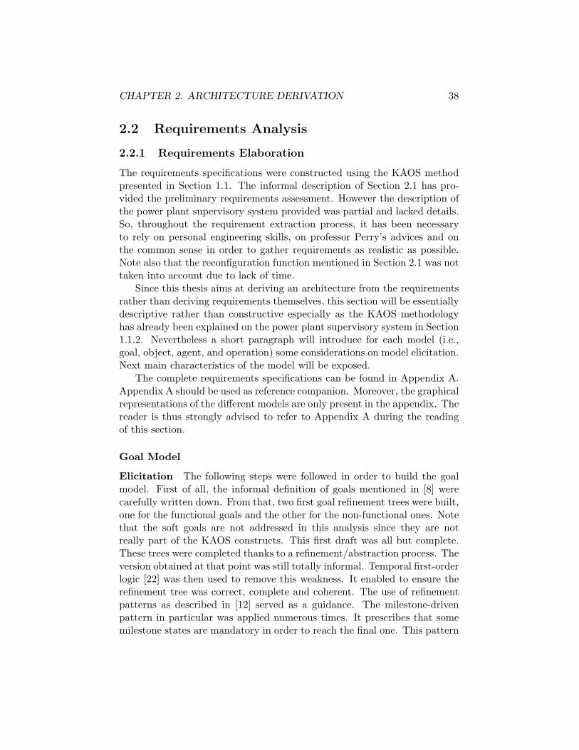
Figure 2.6: Communication reliability refinement subtree
enable it to raise the appropriate alarm. This intermediate state is necessaryto reach the final state, i.e., the raising of the alarm.
In order to build a system as robust as possible, various goals have beenadded to the goal diagram.
Among these a first class takes care of the correct working of all the sen-sors and ensures the data provided is consistent and coherent. As describedin Section 2.1, two types of actions are supported to do so: consistency andsanity checks. Once data have been acquired they have to be validated.This fact is represented by the goal ConsistencyCheckPerformed. Mal-functions of sensors – detected for example by asking suspicious sensors toperform self-tests – should result in switching their status to ’off’, so puttingit off-line. This is the purpose of SanityCheckPerformed.
The second category – represented by the goal DataCorrectlyUpdated– makes sure the updates are well performed by the database. The purposeof some goals is to maintain the power plant in a consistent state (e.g.,FaultStatusUpdated, AlarmStatusUpdated).
The communication has also been constrained in order to prevent anytransmission problems. This is expressed in the NFG diagram (see FigureA.2) through the reliability goals and the performance goal.
The refinement of the goal CommunicationReliability is the result ofthe robustness policy. The goal was refined as shown in Figure 2.6.
To model the data transmission, a relationship at the meta-level hasbeen introduced. It is used to denote that some data has been transmittedfrom a sender agent to a receiver agent. Data can be either a whole objector only a part of it (i.e., a subset of its attributes). Figure 2.7 exhibits thetransmission meta-relationship.
The three subgoals ensure the correctness of the transmission. Theyprescribe that no alteration has occurred on the data transmitted, thatis, no data has been introduced or lost and the sequential order has beenpreserved. They have been formally refined as follows 1:
1Data can either be SensorInformation, FaultInformation, AlarmInformation,

CHAPTER 2. ARCHITECTURE DERIVATION 43
Figure 2.7: Transmission meta-relationship
Goal NoDataIntroduced
FormalDef ∀ x:Data, X:P(Data)2, A1,A2:AgentTransmitted(X,A1,A2) ∧ x ∈ Transmitted(X,A1,A2).content⇒ x ∈ X
Goal NoDataLost
FormalDef ∀ x:Data, X:P(Data),A1,A2:Agentx ∈ X ∧ Transmitted(X,A1,A2)⇒ x ∈ Transmitted(X,A1,A2).content
Goal SequencePreserved
FormalDef ∀ x,y: Data, X:P(Data), A1,A2:Agent, ∃ u,v: Datax,y ∈ X ∧ Before (x,y,X) ∧ Transmitted(X,A1,A2)⇒ u,v ∈ Transmitted(X,A1,A2).content ∧ x =u ∧ y=v∧ Before(u,v,Transmitted(X,A1,A2))
Performance is also a major non-functional goal. Communication is con-strained by a time bound. This is expressed by the NFG Communication-Efficiency. This limit varies throughout the system depending on theimportance of the communication channel. The FaultInformation has tobe transmitted from PRECON to ALARM within 1 second while answeringa request can take a little longer – up to 5 seconds.
The formal definition of this goal depends on the time constraint. If oneconsider for example the transmission of a FaultInformation – which hasthe strongest time constraint – the formalization is a straightened versionof the goal FaultInfoTransmittedWhenFaultDetected:
FaultDiagnosis or AlarmDiagnosis2P(Data) denotes the set of subsets of Data

CHAPTER 2. ARCHITECTURE DERIVATION 44
Goal CommunicationEfficiency
FormalDef ∀ f:Fault, ∃! l:LocationDetected(f,l)⇒ ♦≤1s (∃! fi:FaultInformation)(Representation(fi,f)∧ Transmitted(fi,PRECON,ALARM))
Object Model
Elicication The object model constructed is a model of the compositesystem, that is, it models both real objects and their perception by thesystem. The motivation is to express accuracy goals. Figure A.3 shows theobject diagram. Entities present in the objects were first derived from theinformal definition of the goals. All the concepts of importance were modeledeither under the form of an object or of a relationship. Attributes were thenadded to the different entities in order to characterize them. Some of theattributes were extracted from the problem definition but most of them onlyreflect a necessity. This necessity arises from two main reasons.
First certain goal definitions need the presence of specific attributes.For example the attribute WorkCorrectly of Sensor was needed by thegoal SanityCheckPerformed.
Secondly the properties definition of the various entities – expressed byinvariants – requires specific attributes. As an illustration consider the fol-lowing invariant of the object Alarm which expresses that all the alarms stillactive cannot have a deactivation time:
Activated = true ⇒ DeactivationTime = null
The purpose of certain attributes is to prepare for change. The recon-figuration function was finally not taken into account in the elaborationof the different models due to a lack of time. However it is believed thatthe only effect would be to modify the allowed range of temperatures andpressures. Attributes representing the minimum, the maximum and desiredvalue of both pressure and temperature were consequently added to theobjects SteamCondenser and CoolingCircuit.
Last, a few attributes were added in order to build a more completemodel. The justification was in this case common sense. Among these arethe attributes Type and Power of the object PowerPlant.
The last step of the goal model elaboration was the formalization ofthe domain invariants characterizing the different entities. The model wasrefined many times due to the iterative nature of the requirement extractionprocess.
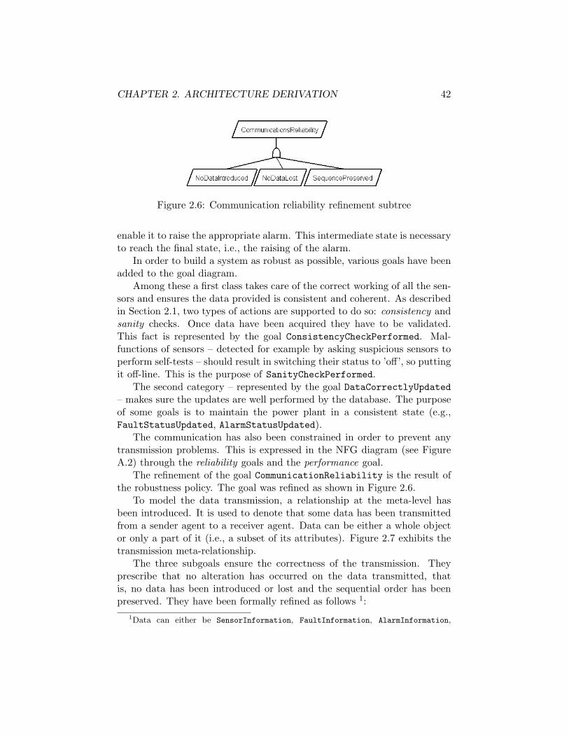
CHAPTER 2. ARCHITECTURE DERIVATION 45
Characteristics The main characteristic of the model is the presence oftwo different levels of representations for the concepts Sensor, Fault andAlarm. The first level refers to the object in itself while the second onerefers to its representation in the software. This distinction was introducedfor robustness reasons. In fact it enables to manage the case where therepresentation of the object is not correct which would be unfortunate butcould happen. The two levels are constrained by an invariant prescribingthat all the attributes have to be identical.
The representation of the three main concepts – Sensor, Fault and Alarm– are linked two by two by a diagnosis relationship. The information pro-vided by the sensor permits the detection of the faults and the descriptionof a fault is the rationale for the raising of an alarm. Consequently therelationship FaultDiagnosis links SensorInformation and FaultInfor-mation while AlarmDiagnosis links FaultInformation and AlarmInfor-mation. Those two relationships are one-one. It is a modelling choice. Ithas been chosen that a fault is the result of one and only one error detectedby one sensor and that each fault raises one and only one alarm. The reasonfor that is the resulting simplicity and the easiness of traceability.
Agent Model
Elicitation The definition of the agents was extracted mostly from [8, 9].Inspiration has been drawn from the existing agents. Each leaf goal fromthe Goal Model was assigned to one of the agents. It was ensured that everyagent has the capacity to assume the responsibility of the goal. By capacityit is meant that every agent could monitor or control, depending on the case,every single variable appearing in the formal definition of a goal the agenthas to ensure. For further details please refer to [19]. Figure A.5 showsthe context diagram expressing controlled and monitored variables of eachagent.
However a new agent was introduced : the Instrumentation Mainte-nance System (IMS). Its purpose is to ensure that all the sensors are workingproperly. It was added in a robustness concern.
Finally the operations needed to operationalize the different goals wereassigned to the responsible agent. This step will be explained later in theOperation Model section.
Characteristics As already said, most of the agents come from the ex-isting system. This is the case for PRECON, ALARM, COMM, DB, Acquisition

CHAPTER 2. ARCHITECTURE DERIVATION 46
Unit and Sensor. The name used in [8] may be different but basically theperformed functions are the same.
PRECON is in charge of the detection of all the faults that might occureither in the cooling circuit or in the steam condenser. ALARM takes care ofthe alarm management. COMM ensures the reliability and the performanceof all the communication throughout the system. Moreover it performs allthe transmissions between agents. DB persistently stores all the data andanswers all the request concerning current values of the sensors, faults andalarms. The Sensor agent continuously measures the field variables andAcquisition Unit acquires data from the sensors. The resulting responsi-bility assignment is presented in Figure A.4.
The additional agent – IMS – has to check whether the sensors are work-ing properly and if the data provided by the sensors are consistent in orderto validate them.
The agents belong to two different categories; they can be either partof the software-to-be or part of the environment. For example, PRECONbelongs to the first class while Sensor belongs to the second one. Thisdistinction in agents results also in a goal differentiation. In fact the goalsassigned to environment agent are expectations while the others are re-quirements. This leads to the introduction of the IMS agent. Sensor isan environment agent and so all the goals assigned to it are expectations.But obviously it cannot be assumed that the goals SanityCheckPerformedand ConsistencyCheckPerformed will be true without the intervention ofa reliable software device. Moreover those kind of tests should not be theresponsibility of the Sensor from a conceptual point of view.
Operation Model
Elicitation The operation model was the the last one to be constructedbecause it relies on a precise formal definition of the goals in order to bederived automatically. The operations contained in the model were derivedin such a way that they operationalize some goal present in the goal model.A complete operationalization of a goal is a set of operations (described bytheir pre-, trigger- and postconditions) that guarantee the satisfaction ofthat goal if the operations are applied. It is where all the difficulty lies:finding complete operationalizations. An extensive use of the operational-ization patterns described in [20] has been made in order to derive completeoperation specifications. It enabled to save a lot of time on proofs. It iseven more true than for the goal refinement pattern as the application ofthe operationalization pattern has been found very systematic.

CHAPTER 2. ARCHITECTURE DERIVATION 47
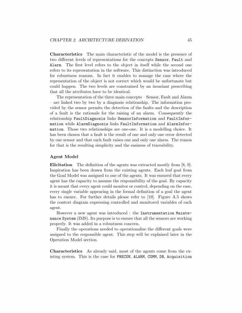
Figure 2.8: Bounded achieve opeartionalization pattern
Two patterns were particularly useful and have been used numeroustimes. The first one is the bounded achieve pattern described in Figure 2.8.Its applicability condition (i.e., C ⇒ ♦≤dT ) makes it very popular. In factmost system goals have that form. The operation specification prescribesthat ¬T becomes T as soon as C ∧ ¬T holds for d − 1 time units. It isthen straightforward to see that such a specification operationalizes the goalC ⇒ ♦≤dT .
The second most useful pattern was the immediate achieve pattern de-scribed in Figure 2.9. Its applicability condition prescribes that the finalstate T has to be reached as soon as C becomes true. In this case it is a bitmore difficult to see why the satisfaction of the two operations guaranteesthe satisfaction of the goal. A intuitive explanation why will be given butthe interested reader can find a complete proof in [20]. The first operationprescribes that as soon C becomes true the operation must be applied if¬T holds in order to reach the final state T . The second operation maybe applied when C does not hold if the precondition T is true, making thepostcondition ¬T true.
Once all the operations derived, they were assigned to the agent respon-sible for the goal operationalized by those operations.
Characteristics This section presents an illustration of the two opera-tionalization patterns forementioned.
Concerning the first pattern, the operationalization of the goal Fault-InformationTransmittedWhenFaultDetected will be examined. Its formaldefinition is given by
Goal FaultInformationTransmittedWhenFaultDetected
CHAPTER 2. ARCHITECTURE DERIVATION 48
Figure 2.9: Immediate achieve operationalization pattern
FormalDef ∀ f:Fault, ∃! l:LocationDetected(f,l) ⇒ ♦ (∃! fi:FaultInformation) (Representation(fi,f)∧ Transmitted(fi,PRECON,ALARM))
The pattern presented in Figure 2.8 can be instantiated using the fol-lowing parameters:
C : Detected(f,l) ∧ Representation(fi,f)T : Transmitted(fi,PRECON,ALARM)
The operation resulting from the application of the pattern is:
Operation TransmitFaultInformation
DomPre ¬ Transmitted(fi,PRECON,ALARM)
DomPost Transmitted(fi,PRECON,ALARM)
ReqTrig for FaultInformationTransmittedWhenFaultDetected¬ Transmitted(fi,PRECON,ALARM) S=1ms Detected(f,l∧ Representation(fi,f) ∧ ¬ Transmitted(fi,PRECON,ALARM)
Note that as d − 1 time units makes here zero a smaller time unit issimply taken.
To illustrate the second pattern consider the goal SanityCheckPerformedwhose formal definition is given by
Goal SanityCheckPerformed
FormalDef ∀ s:Sensor¬ s.workingProperly ∧ s.status=’on’ ⇒ ◦ s.status=’off’
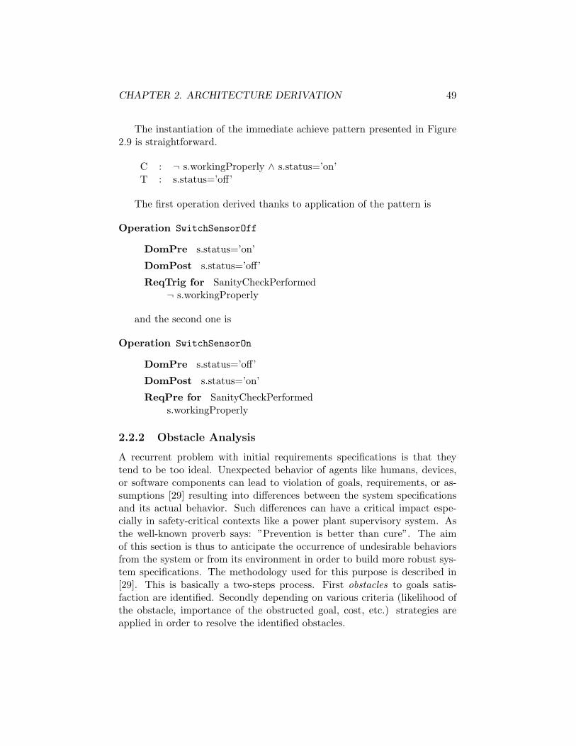
CHAPTER 2. ARCHITECTURE DERIVATION 49
The instantiation of the immediate achieve pattern presented in Figure2.9 is straightforward.
C : ¬ s.workingProperly ∧ s.status=’on’T : s.status=’off’
The first operation derived thanks to application of the pattern is
Operation SwitchSensorOff
DomPre s.status=’on’
DomPost s.status=’off’
ReqTrig for SanityCheckPerformed¬ s.workingProperly
and the second one is
Operation SwitchSensorOn
DomPre s.status=’off’
DomPost s.status=’on’
ReqPre for SanityCheckPerformeds.workingProperly
2.2.2 Obstacle Analysis
A recurrent problem with initial requirements specifications is that theytend to be too ideal. Unexpected behavior of agents like humans, devices,or software components can lead to violation of goals, requirements, or as-sumptions [29] resulting into differences between the system specificationsand its actual behavior. Such differences can have a critical impact espe-cially in safety-critical contexts like a power plant supervisory system. Asthe well-known proverb says: ”Prevention is better than cure”. The aimof this section is thus to anticipate the occurrence of undesirable behaviorsfrom the system or from its environment in order to build more robust sys-tem specifications. The methodology used for this purpose is described in[29]. This is basically a two-steps process. First obstacles to goals satis-faction are identified. Secondly depending on various criteria (likelihood ofthe obstacle, importance of the obstructed goal, cost, etc.) strategies areapplied in order to resolve the identified obstacles.

CHAPTER 2. ARCHITECTURE DERIVATION 50
The obstacle identification and coverage presented here is not exhaustive.It has been focused on ”critical goals”, that is, goals thought as the mostimportant with respect to the general purpose of the system.
Fault Detection
The first key function is the fault detection. FaultDetectedWhenCalcula-tionDone is thus the first goal considered. Its formal definition is:
Goal FaultDetectedWhenCalculationDone
FormalDef ∀ f:Fault, l:LocationCalculationDone ∧ Occurs(f,l) ⇒ ♦ Detected(f,l)∧
CalculationDone ∧ ¬Occurs(f,l) ⇒ � ¬Detected(f,l)
Obstacles will be generated using regression for this first goal. For theanalysis purpose, this goal will be further AND-refined into the two followingsubgoals:
(G1) ∀ f:Fault, l:LocationCalculationDone ∧ Occurs(f,l) ⇒ ♦ Detected(f,l)
(G2) ∀ f:Fault, l:LocationCalculationDone ∧ ¬Occurs(f,l) ⇒ � ¬Detected(f,l)
The negation of the goals is given by:
(NG1) ♦ ∃ f:Fault, l:LocationCalculationDone ∧ Occurs(f,l) ∧ � ¬ Detected(f,l)
(NG2) ♦ ∃ f:Fault, l:LocationCalculationDone ∧ ¬ Occurs(f,l) ∧ ♦ Detected(f,l)
The domain contains the two following property:
(D1) ∀ f:Fault, l:Location, ∃ s:SensorDetected(f,l) ⇒ Monitors(s,l) ∧ s.Status=on
∧ s.DataValue /∈ AllowedRange(D2) ∀ f:Fault, l:Location, s:Sensor
¬ Detected(f,l) ⇒ ¬ Monitors(s,l) ∨ s.Status=off∨ s.DataValue ∈ AllowedRange

CHAPTER 2. ARCHITECTURE DERIVATION 51
The property states that a necessary and sufficient condition for a faultdetection is the presence of some working sensor monitoring the fault lo-cation with a value outside an allowed range. The second property statesif a fault is not detected there cannot be a working sensor monitoring thefault location with a value outside the allowed range. These rules can berewritten by contraposition:
(D1’) ∃ f:Fault, l:Location, ∀ s:Sensor¬ Monitors(s,l) ∨ s.Status=off ∨ s.DataValue ∈ AllowedRange
⇒ ¬ Detected(f,l)(D2’) ∃ f:Fault, l:Location, s:Sensor
Monitors(s,l) ∧ s.Status=on ∧ s.DataValue /∈ AllowedRange⇒ Detected(f,l)
The right part of the equivalence in (D1’) unifies with a literal in (NG1);regressing through (NG1) through (D1’) then amounts to replacing in (NG1)the matching consequent in (D1) by the corresponding antecedent. Let’sproceed similarly for (D2’) and (NG2). The two following potential obstacleshave thereby been formally derived:
(O1) ♦ ∃ f:Fault, l:Location, ∀ s:SensorCalculationDone ∧ Occurs(f,l)
∧ � [ ¬ Monitors(s,l)∨ s.Status=off∨ s.DataValue ∈ AllowedRange]
(02) ♦ ∃ f:Fault, l:Location, s:SensorCalculationDone ∧ ¬ Occurs(f,l)
∧ ♦ [ Monitors(s,l) ∧ s.Status=on∧ s.DataValue /∈ AllowedRange]
Obstacle 1 covers three situations, namely, the first where no sensormonitors the location where the fault occurs, the second where no sensoris working and the third where a fault effectively occurs while the value ofthe sensor is in the allowed range, the allowed range being thus not enoughrestrictive. Using OR-refinement three subobstacles could thereby be iden-tified: LocationNotMonitored, AllSensorOff and DetectionCriterion-NotStrictEnough.
Obstacle 2 covers the situation where there is a working sensor monitor-ing some location whose value is outside the allowed range while no faultoccurs in that location. This leads to the obstacle DetectionCriterion-TooStrict. The situation is summarized in Figure 2.10.
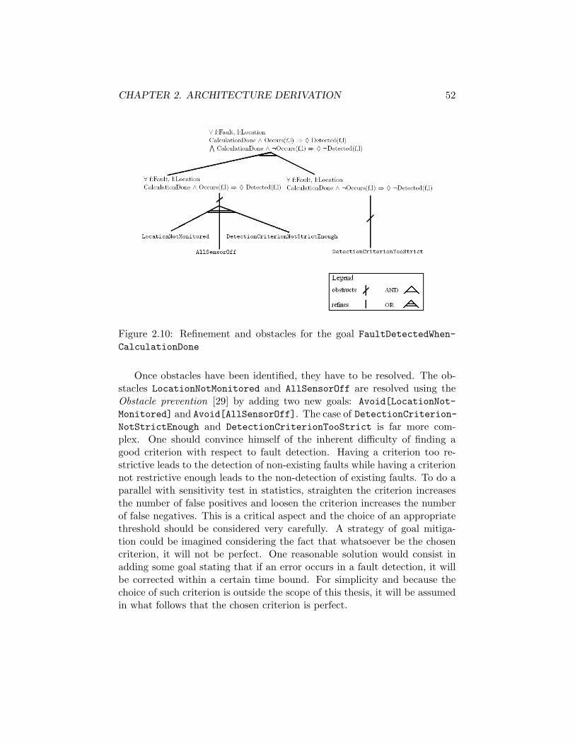
CHAPTER 2. ARCHITECTURE DERIVATION 52
Figure 2.10: Refinement and obstacles for the goal FaultDetectedWhen-CalculationDone
Once obstacles have been identified, they have to be resolved. The ob-stacles LocationNotMonitored and AllSensorOff are resolved using theObstacle prevention [29] by adding two new goals: Avoid[LocationNot-Monitored] and Avoid[AllSensorOff]. The case of DetectionCriterion-NotStrictEnough and DetectionCriterionTooStrict is far more com-plex. One should convince himself of the inherent difficulty of finding agood criterion with respect to fault detection. Having a criterion too re-strictive leads to the detection of non-existing faults while having a criterionnot restrictive enough leads to the non-detection of existing faults. To do aparallel with sensitivity test in statistics, straighten the criterion increasesthe number of false positives and loosen the criterion increases the numberof false negatives. This is a critical aspect and the choice of an appropriatethreshold should be considered very carefully. A strategy of goal mitiga-tion could be imagined considering the fact that whatsoever be the chosencriterion, it will not be perfect. One reasonable solution would consist inadding some goal stating that if an error occurs in a fault detection, it willbe corrected within a certain time bound. For simplicity and because thechoice of such criterion is outside the scope of this thesis, it will be assumedin what follows that the chosen criterion is perfect.

CHAPTER 2. ARCHITECTURE DERIVATION 53
Transmission of fault informations from PRECON to ALARM
Once a fault has been detected, information on the occurring fault haveto be transmitted from PRECON to ALARM in order to raise the appropriatealarm. The goal considered here is FaultInformationTransmittedWhen-FaultDetected. Its definition3 is given by:
Goal FaultInformationTransmittedWhenFaultDetected
FormalDef ∀ f:Fault, l:Location, ∃! fi:FaultInformationDetected(f,l) ⇒ ♦ Transmitted(fi,PRECON,ALARM)∧ Representation(fi,f)
The following domain property states that a necessary condition to thetransmission of data from A1 to A2 is the correct operation of the sourceand the target of the transmission and of the communication channel (C).This property can be instantiated to PRECON, ALARM and COMM as follows:
(D) ∀ fi:FaultInformationTransmitted(fi, PRECON, ALARM) ⇒ Operating(PRECON)
∧ Operating(ALARM) ∧ Operating(COMM)
Proceed similarly to what has been done for fault detection leads to thefollowing obstacle:
(O) ♦ ∃ f:Fault, l:Location, ∀ fi:FaultInformationDetected(f,l) ∧ � [¬ Operating(PRECON)
∧ ¬ Operating(ALARM) ∧ ¬ Operating(COMM)∧ ¬ Representation(fi,f)]
This obstacle mainly covers two situations, one where either PRECON,ALARM or COMM does not operate and the other where the transmittedfault information does not describe correctly the detected fault. Four subob-stacles are thereby identified: PRECONNotOperating, ALARMNotOperating,COMMNotOperating, IncorrectFaultInformationTransmitted. One can-not afford to have one of these components down for whatever reason. Conse-quently, Fault-tolerant communication is added between PRECON and ALARMresulting in the addition of the new goal Maintain[FaultTolerantCommu-nication(PRECON,ALARM)].
3A FaultInformation fi is the representation of a Fault f iff all their attributes areequal

CHAPTER 2. ARCHITECTURE DERIVATION 54
The last obstacle corresponds to a classic problem where the representa-tion in the software of an environment object is incorrect. This problem hasbeen solved by adding the accuracy goal Maintain[AccurateRepresenta-tion(fi,f)]. This problem can be extended to the whole set of softwarerepresentations of environments objects and similar goals are consequentlyadded for SensorInformation and AlarmInformation.
Data Acquisition
Since all the system relies on the data collected by the sensors, data acqui-sition is also a critical function. For brevity purpose, the entire obstacleanalysis will not be exposed but one will rather concentrate on the keyaspects emerging from such an analysis.
The first recurring obstacle is InfoOutdated. For example, data pro-vided by a sensor can be diagnosed as inconsistent even though this is nolonger the case just because sensor information is outdated. Moreover out-dated sensor information value can lead to wrong fault detection when theactual sensor value is no longer outside the allowed range or to undetectedfaults when the fault occurs between two updates. The solution to thatproblem is to perform data acquisitions more often.
Surprisingly, updates can also be realized too quickly. An obstacle to thegoal SanityCheckPerformed is the situation where the sensor is turned offwhile it is starting to work correctly again. Dually a sensor could be turnedon while it is starting to behave incorrectly again. It is however very un-likely this situation takes place and the Do-nothing strategy is consequentlyapplied.
A third problem can arise from the fact that sensor information aremodified by two different agents, namely Acquisition Unit and IMS. Ac-quisition of data could take place while sensors are currently being turnedoff because of a malfunction. This would lead to undesirable inconsisten-cies. It has thereby been decided to add the goal Maintain[Accurate-Data(Acquisition Unit,IMS)] ensuring that both Acquisition Unit andIMS have accurate and coherent information on sensors.
Conclusion
The conducted obstacle analysis, although not complete, enabled to pin-point some important unforeseen potential problems. The presence of alocation not monitored, the absence of a working sensor, and an ill cho-sen detection criterion have been identified as obstacles to fault detection.

CHAPTER 2. ARCHITECTURE DERIVATION 55
Inconsistencies between representations of environment objects and the ob-jects themselves are general problem affecting the entire system. Non op-erating agents could be an obstacle to the correct operations of the systempreventing critical functions such as fault detection, transmission of faultinformation from PRECON to ALARM and alarm raising. The issue of the timeinterval between two successive data acquisitions has been recognized as cru-cial. The potential incoherences resulting from the concurrent modificationson SensorInformation by Sensor and ManagementUnit agents have alsobeen demonstrated.
Different strategies have been applied to solve the envisioned obstaclessuch as goal prevention, goal mitigation. Various goals have been addedto the goal model in order to build a more robust system. Added goalsare all non-functional and belong to different categories. Avoid[Location-NotMonitored] and Avoid[AllSensorOff]) are safety goals. Maintain-[FaultTolerantCommunication(PRECON,ALARM)] is a reliability goal. Main-tain[AccurateRepresentation(fi,f)] and Maintain[AccurateData(Ac-quisitionUnit,IMS)] are accuracy goals. Figure A.6 exhibits the non-functional requirements added by the obstacle analysis. One should alsonote the process of obstacle analysis can be iterative. In fact, the addedgoals could also be subject to various obstacles. However, an additionalobstacle analysis has not been performed because the system is thought tobe robust enough.

CHAPTER 2. ARCHITECTURE DERIVATION 56
2.3 Architecture Derivation
This section presents the application of the two methods exposed in Sections1.3.1 and 1.3.2 on the requirements elaborated in Section 2.2. For eachmethodology, the intermediate results and the derivation process will becommented. Afterward the two resulting architectures will be compared indetails.
2.3.1 Using the KAOS Method
The architecture in this section will be derived using the method describedin Section 1.3.1. The method prescribes the use of three different steps.The first step consists of the derivation of an abstract dataflow architecturefrom the KAOS specifications. This first draft is next refined using style inorder to meet architectural constraints. The architecture obtained is finallyrefined using design patterns so as to achieve non-functional requirements.One section will be devoted to each step.
Step 1: From software specifications to abstract dataflow archi-tectures
The first architecture is obtained from data dependencies between the dif-ferent agents. The agents become software components while the data de-pendencies are modeled via dataflow connector. The followed procedure isdivided into two sub-steps.
1. Each agent that assumes the responsibility of a functional goal assignedto the software-to-be, becomes a software component together with itsoperations.
2. For each pair of components C1 and C2, drive a dataflow connectorbetween C1 and C2 if:
DataFlow(d,C1,C2) ⇔ Controls(C1,d) ∧ Monitors(C2,d)
This step is very systematic. From the context diagram shown in FigureA.5 it was needed to get rid off the environment agents to obtain the abstractdataflow architecture. The result is presented in Figure 2.11.
One can note certain features. Two components seem to be “absorbent”:COMM and DB. Four dataflow connectors come to each of them but none comesfrom them. This is caused by the fact neither COMM nor DB does control any

CHAPTER 2. ARCHITECTURE DERIVATION 57
Figure 2.11: Abstract dataflow architecture
variables. In fact COMM carries all the data between the different componentsbut does not perform any modification and DB stores all the data withoutany modification. Moreover there is a dataflow connector between PRECONand ALARM while the real data flow goes through COMM. A similar situationalso happens between Acquisition Unit and PRECON. The real data flowshould pass from DB through COMM but there is no dataflow derived.
It is believed that the underlying cause is the presence of low-level agents– DB and COMM – performing low-level functionalities – storage and transmis-sion of data respectively – in the requirements. They were however needed toachieve certain goals. The resulting dataflow architecture may then appearquite strange.
Step 2: Style-based architectural refinement to meet architecturalconstraints
In this step, the architectural draft obtained from step 1 is refined by im-posing a “suitable” style, that is, a style whose underlying goal matches thearchitectural constraints. The main architectural constraint of this system[8, 9, 10] is that all the components should be distributed. In fact, in thereal system, only PRECON has to be built and it has to integrate in a pre-

CHAPTER 2. ARCHITECTURE DERIVATION 58
Figure 2.12: Centralized communication architectural style
existing architecture characterized by centralized communications and bydistributed components.
The only transformation rule mentioned in [27] did not match this ar-chitectural constraints so a new one had to be designed. However, evenif the transformation rule does not correspond, the produced architectureis centralized. The designed rule can therefore be seen as a variation ofthe event-based style where the transformation and the source architecturefragment are different while the target architecture fragment is similar. TheCOMM component plays in this case the role of broker. The resulting trans-formation rule is shown in Figure 2.12.
This style was applied on the architectural draft and the result is shownin Figure 2.13. The situation described by the rule arises 7 times, proof thatthe style constrains globally the architecture. Note that for presentationpurpose, arrows coming from the COMM component to DB have been merged.
The architecture looks now closer to what was expected. Every singlecommunication is achieved in a centralized way through the communicationmodule. The architectural constraints are now met.
Nevertheless, one “absorbent” component subsists: DB.
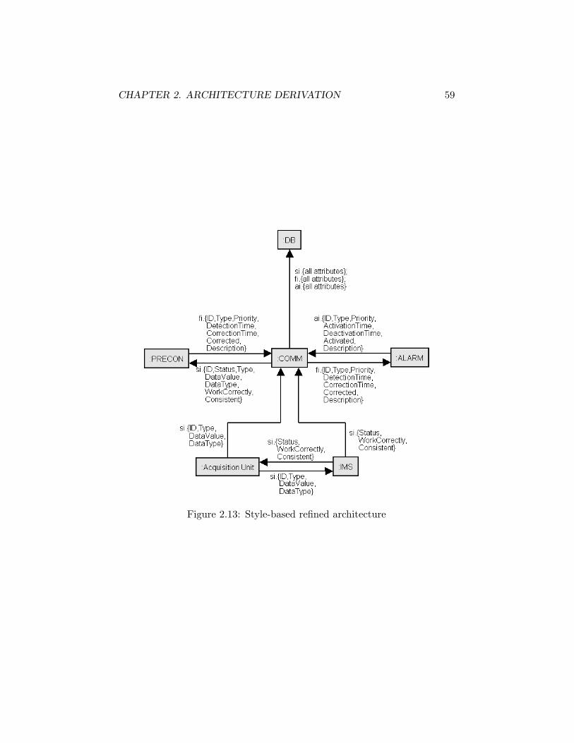
CHAPTER 2. ARCHITECTURE DERIVATION 59
Figure 2.13: Style-based refined architecture

CHAPTER 2. ARCHITECTURE DERIVATION 60
Figure 2.14: Fault-tolerant refinement pattern
Step 3: Pattern-based architecture refinement to achieve non-functional requirements
The purpose of this last step is to refine further the architecture in or-der to achieve the non-functional requirements. Those can belong to twomain categories; they can be either quality-of-service or development goals.Quality-of-service goals include, among others, security, accuracy and us-ability. Development goals encompass desirable qualities of software such aslow coupling, high cohesion and reusability.
This step refines the architecture in a more local way than the previousone. Patterns are used instead of styles.
Two refinement patterns were used on the system. They come both from[27]. The first one is presented in Fig. 2.14. Thanks to the conducted obsta-cle analysis, the potential problems that could result from a misbehavior ofeither PRECON or ALARM have been pointed out. A fault-tolerant communica-tion between those two components was required because they form the coreof the system. They perform the most critical functions (i.e., the fault de-tection and the alarm management). This is the reason why those moduleswere desired to be as resistant as possible to any kinds of failure. The non-functional goal Maintain[FaultTolerantCommunication(PRECON,ALARM)]was therefore added. One could note than the pattern was not applied ex-actly according to its definition (see Figure 2.14). The presence of the com-ponent COMM between PRECON and ALARM was however ignored because it isbelieved it has no influence on the capacity of the pattern to achieve its goal.
The second refinement pattern used is shown in Figure 2.15. As theprevious one, its introduction was motivated by the obstacle analysis. Itpinpoints the potential incoherence and inconsistency problems that couldarise since both Acquisition Unit and IMS access and modify the samedata, namely information on sensor. The goal Maintain[AccurateData(Ac-
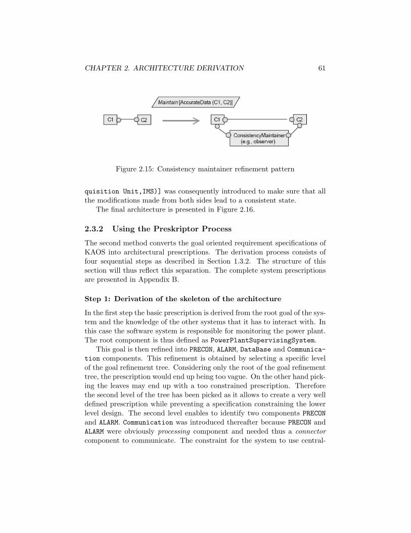
CHAPTER 2. ARCHITECTURE DERIVATION 61
Figure 2.15: Consistency maintainer refinement pattern
quisition Unit,IMS)] was consequently introduced to make sure that allthe modifications made from both sides lead to a consistent state.
The final architecture is presented in Figure 2.16.
2.3.2 Using the Preskriptor Process
The second method converts the goal oriented requirement specifications ofKAOS into architectural prescriptions. The derivation process consists offour sequential steps as described in Section 1.3.2. The structure of thissection will thus reflect this separation. The complete system prescriptionsare presented in Appendix B.
Step 1: Derivation of the skeleton of the architecture
In the first step the basic prescription is derived from the root goal of the sys-tem and the knowledge of the other systems that it has to interact with. Inthis case the software system is responsible for monitoring the power plant.The root component is thus defined as PowerPlantSupervisingSystem.
This goal is then refined into PRECON, ALARM, DataBase and Communica-tion components. This refinement is obtained by selecting a specific levelof the goal refinement tree. Considering only the root of the goal refinementtree, the prescription would end up being too vague. On the other hand pick-ing the leaves may end up with a too constrained prescription. Thereforethe second level of the tree has been picked as it allows to create a very welldefined prescription while preventing a specification constraining the lowerlevel design. The second level enables to identify two components PRECONand ALARM. Communication was introduced thereafter because PRECON andALARM were obviously processing component and needed thus a connectorcomponent to communicate. The constraint for the system to use central-

CHAPTER 2. ARCHITECTURE DERIVATION 62
Figure 2.16: Pattern-based refined architecture
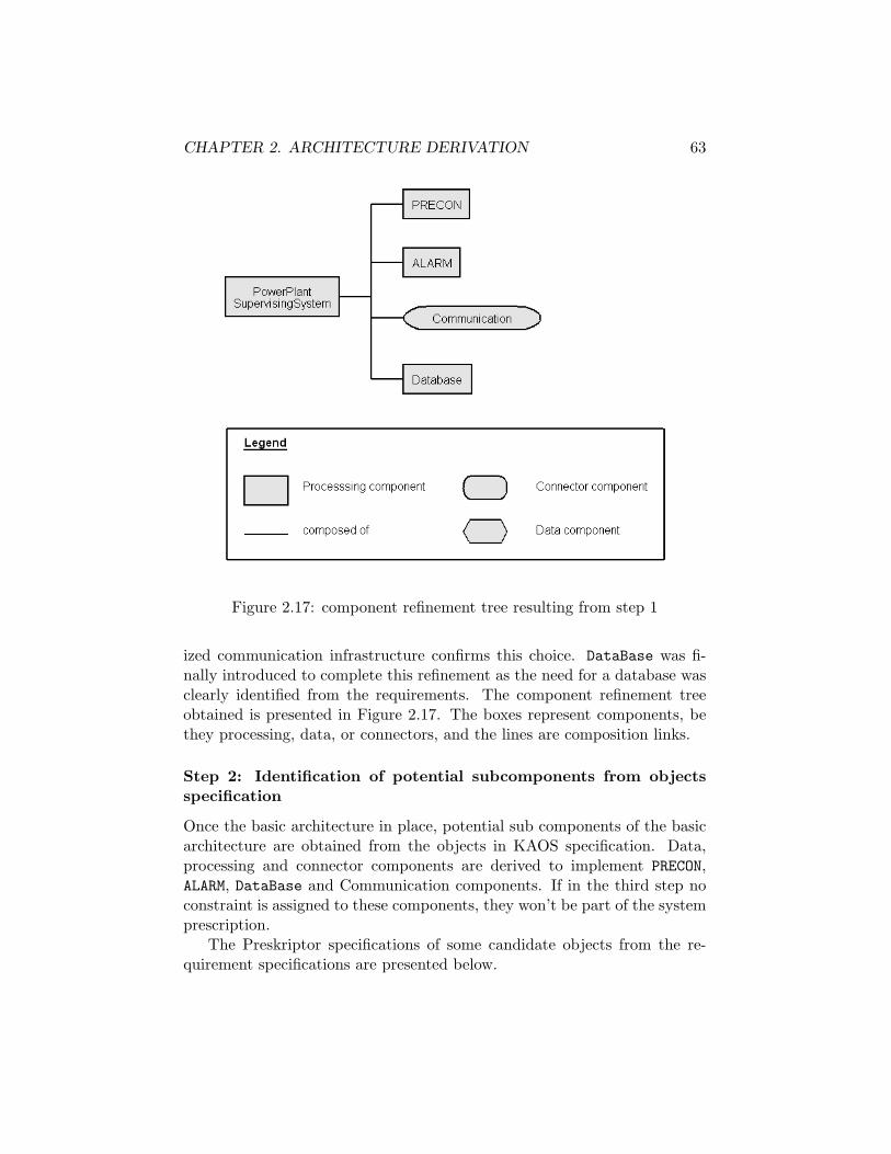
CHAPTER 2. ARCHITECTURE DERIVATION 63
Figure 2.17: component refinement tree resulting from step 1
ized communication infrastructure confirms this choice. DataBase was fi-nally introduced to complete this refinement as the need for a database wasclearly identified from the requirements. The component refinement treeobtained is presented in Figure 2.17. The boxes represent components, bethey processing, data, or connectors, and the lines are composition links.
Step 2: Identification of potential subcomponents from objectsspecification
Once the basic architecture in place, potential sub components of the basicarchitecture are obtained from the objects in KAOS specification. Data,processing and connector components are derived to implement PRECON,ALARM, DataBase and Communication components. If in the third step noconstraint is assigned to these components, they won’t be part of the systemprescription.
The Preskriptor specifications of some candidate objects from the re-quirement specifications are presented below.

CHAPTER 2. ARCHITECTURE DERIVATION 64
Component Fault
Type Data
Constraints . . .
Composed of . . .
Component FaultInformation
Type Data
Constraints . . .
Composed of . . .
Component SensorConnect
Type Connector
Constraints . . .
Composed of . . .
Component QueryManager
Type Processing
Constraints . . .
Composed of . . .
One can note that the Database component defined in step 1 would havebeen derived automatically since a database object is present in the KAOSobject model.
Since all the components derived from KAOS specifications are data,various processing components need to be defined at this stage to effectivelyimplement the component from step 1. In the same way connector com-ponents are specified to permit communication between the newly definedcomponents. The latest two components forementioned are an example. Atthe next stage it will be decided which of these components would be partof the final prescription based on the assignment of the goals responsibility.The decision will be guided by the goal diagram. The components of step1 come from goals present in the goal diagram and are thus roots of goalssubtrees. Since goal definitions are expressed in terms of objects one looks,in which subtree is the object from which a component is derived. Of coursesome objects can be present in the definitions of goals in two different sub-trees. The choice is then based on what goal this object is the most relatedto. This is fairly qualitative though.

CHAPTER 2. ARCHITECTURE DERIVATION 65
Step 3: Selection among potential components via constraints as-signment
In this step it is determined which of the subgoals are achieved by the systemand they are assigned to the previously defined components. With the goalrefinement tree as reference, it is decided which of the potential componentsof step two would take the responsibility of the various goals. Note that thisis a design decision made by the architect based on the way he or she choosesto realize the system. The components with no constraints are discarded,and it is ended up with the first complete prescription of the system.
Components like Fault were discarded from the prescription becausethey were not necessary to achieve the sub goals of the system. Instead ofthe Fault component it was chosen to keep FaultInformation. This choicewas motivated by the fact FaultInformation is the software representationof Fault. Different architects may use different approaches.
It is interesting to note that in the first iteration of the prescriptionCommunication was a leaf connector with no subcomponents. It was respon-sible for realizing the necessary communication of the system. However thepower plant communication was not uniform throughout the system. Duringthe first iteration it was assumed that Communication component could han-dle these varying types of requirements. However it was then realized thatcreating sub components for Communication component could help to illus-trate these differences. Therefore the sub components - UpdateDBConnect,FaultDetectionEngineAlarmManagerConnect and QueryDBConnect werecreated. As their name suggests, each of them is responsible for the com-munication in different parts of the system. It was therefore easier to illus-trate the different time and security constraints needed for each of them.Note that the fault tolerance requirement introduced after obstacle anal-ysis constrains the connector linking the processing components in chargeof fault detection and alarm management, namely FaultDetectionEngineand AlarmManager.
Please find below the prescriptions for the sub components:
Component UpdateDBConnect
Type Connector
Constraints SecureTimeConstraint = 2 s
Composed of /
Uses /

CHAPTER 2. ARCHITECTURE DERIVATION 66
Component QueryDBConnect
Type Connector
Constraints TimeConstraint = 5 s
Composed of /
Uses /
Component FaultDetectionEngineAlarmManagerConnect
Type Connector
Constraints TimeConstraint = 1 sSecureMaintain[FaultTolerantCommunication(PRECON,ALARM)]
Composed of /
Uses /
Figure 2.18 shows the resulting component refinement tree.
Step 4: Architecture refinement to achieve non-problem goals
An additional fourth step in the prescription design process focuses on thenon-functional requirements. Goals like reusability, reliability, etc. can beachieved by refining the prescription. This step is iterated till all the nondomain goals are achieved.
During step 2, the fault-tolerant constraint has been added on the con-nector linking ALARM and PRECON. However the architecture in itself wasnot constrained so to ensure fault tolerance. Additional architectural con-straints were thereby added to the connector and two copies of both PRECONand ALARM were introduced. The constraints added state for example thatonly one copy should work at a time and that whenever a failure of theactive copy occurs the other one should take the relay.
A comprehensive list of additional constraints together with the modifiedsystem prescriptions is presented in Appendix B.2.
Box-and-line diagram
Once the architecture created, a box-and-line diagram was added to illus-trate the various components and connectors. The component tree createdas a result of the three steps did not show how the various components are

CHAPTER 2. ARCHITECTURE DERIVATION 67
Figure 2.18: Component refinement tree resulting from step 3

CHAPTER 2. ARCHITECTURE DERIVATION 68
Figure 2.19: Box-and-line diagram
linked through the connectors. The box-and-line diagram helps in visual-izing this and gives a more complete view of the architecture. Figure 2.19shows the resulting diagram.
2.3.3 Comparing the Resulting Architectures
This section will focus on derived architecture characteristics strictly speak-ing. The general differences such as the formalism used, the level of detailsprovided, the way non-functional requirements are addressed will be exam-ined in Section 2.4.3. First the architectures will be examined with regardto their components in order to check whether they share a subset of com-ponents. If some components are missing in an architecture, the reasonwill be stated. Secondly the presence of an internal structure will be dis-cussed. The ability of the architecture to meet the architectural constraintwill then be assessed. Finally the way the two architectures deal with thenon-functional goals imposing fault-tolerant communication between PRECON

CHAPTER 2. ARCHITECTURE DERIVATION 69
and ALARM and ensuring accurate data between Acquisition Unit and IMSwill be inspected.
For reporting purpose, it will thereafter be referred to the architecturederived by the KAOS method by architecture number one and to the onederived using the Preskriptor process by architecture number two.
The two derived architectures have similarities but also differences. Firsta set of components are common to both architectures. Among those thetwo main components of the system, namely PRECON and ALARM, the com-munication facilities and the database. The functions performed by thosecomponents are roughly equivalent except for PRECON. In fact, the first ar-chitecture assigns to it as sole function fault detection while the secondone adds it sensors management. This results into two additional compo-nents in the first architecture, one for data acquisition and the other fordata validation and sensor operation checking. Since fault detection andsensor management are two separate concerns, the first architecture can beconsidered as better with respect to the high cohesion design heuristic.
An other important aspect is that the second architecture is hierarchi-cally structured while the first one is not. The components are consideredas a whole in the first architecture while they have an internal structure inthe second one. The case of PRECON is symptomatic. It is composed of foursubcomponents – one processing, two data, and one connector component.
One architectural constraint identified from the domain was the use ofa centralized communication infrastructure. In both architectures this re-quirement is met. This is clearly the case in the first one. One can convincehimself by a single at Figure 2.16. This results from the application of cen-tralized communication style defined in Figure 2.12. The situation is less ob-vious in the second architecture because of the multiple connectors defined.Nonetheless all the connectors used for interaction between PRECON, ALARMand Database belong to the same component, namely Communication. Thecommunication can thereby be said centralized. However, there is some in-ternal communication into the PRECON component. It results from the factthat FaultDetectionEngine needs the measured values of the variablesmonitored by sensors stored in the SensorInformation component in orderto detect faults in the power plant.
The obstacle analysis has enabled to identify the fault tolerance require-ment for the communication between PRECON and ALARM. The way botharchitectures address this issue have common points. Two copies of thecomponents are introduced. There are nevertheless some differences. In thefirst architecture, a connector links the copies and each copy of PRECON islinked to one copy of ALARM. In the second architecture, there is no linking
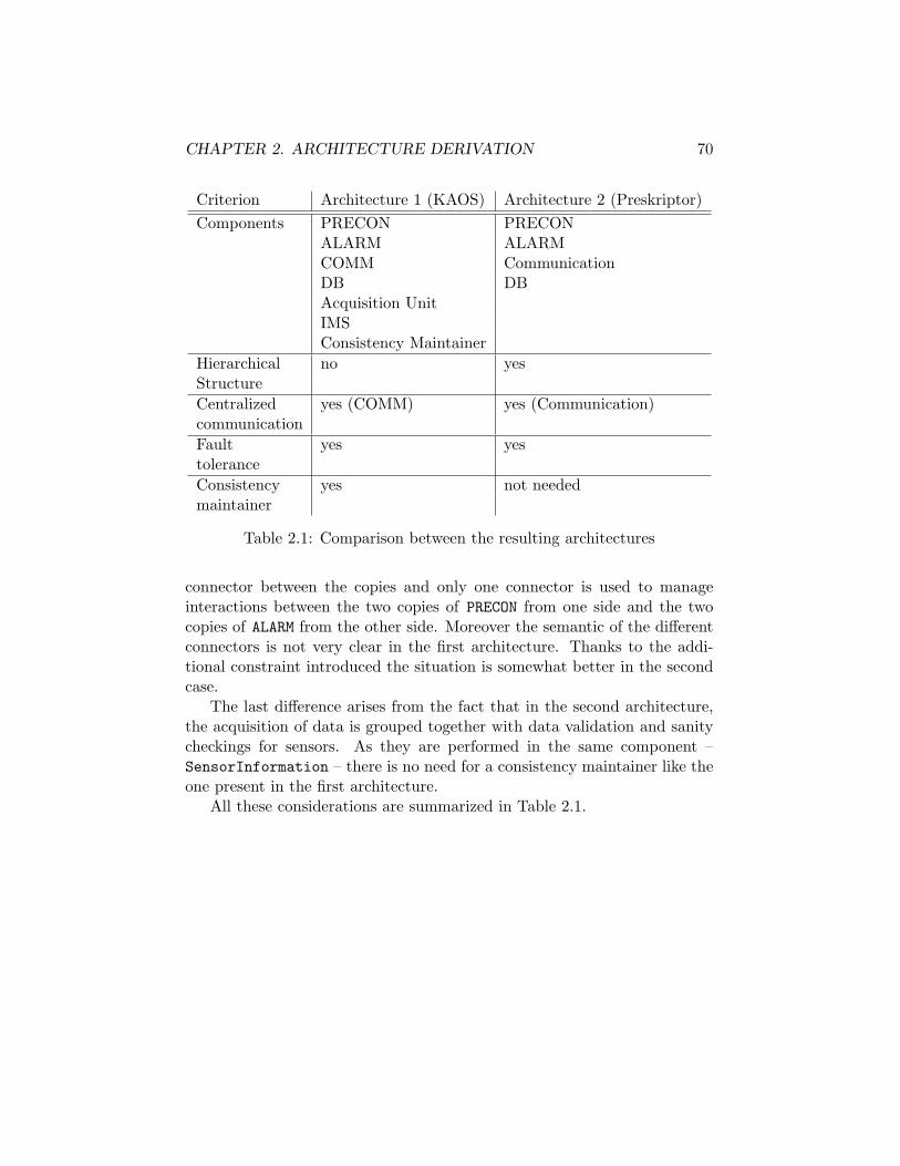
CHAPTER 2. ARCHITECTURE DERIVATION 70
Criterion Architecture 1 (KAOS) Architecture 2 (Preskriptor)Components PRECON PRECON
ALARM ALARMCOMM CommunicationDB DBAcquisition UnitIMSConsistency Maintainer
Hierarchical no yesStructureCentralized yes (COMM) yes (Communication)communicationFault yes yestoleranceConsistency yes not neededmaintainer
Table 2.1: Comparison between the resulting architectures
connector between the copies and only one connector is used to manageinteractions between the two copies of PRECON from one side and the twocopies of ALARM from the other side. Moreover the semantic of the differentconnectors is not very clear in the first architecture. Thanks to the addi-tional constraint introduced the situation is somewhat better in the secondcase.
The last difference arises from the fact that in the second architecture,the acquisition of data is grouped together with data validation and sanitycheckings for sensors. As they are performed in the same component –SensorInformation – there is no need for a consistency maintainer like theone present in the first architecture.
All these considerations are summarized in Table 2.1.

CHAPTER 2. ARCHITECTURE DERIVATION 71
2.4 Discussion
2.4.1 Evaluating the Methods
This section will evaluate the two methods used. In a first time the deriva-tion process will be examined. Since in both cases it consists of interme-diate steps, each one will be carefully examined. Various concerns will bereviewed such as the easiness of application, the level of guidance/freedomprovided/allowed, the issues encountered during the architecture derivation.In a second time the formalism used will be studied considering its advan-tages and disadvantages in terms of capabilities/limitations . Thirdly themapping from the requirements will be examined. Finally the remaining gapbetween the final architecture and the implementation will be discussed.
The KAOS Method
Once the requirements finalized, the first step allows to get an abstractdataflow architecture. Dataflow architecture is obtained by using functionalgoals assigned to software agents. The agents become architectural com-ponents and then dataflow connectors are derived from data dependencies.This stage is fairly systematic and its application is thus straightforward.The abstract dataflow architecture can be obtained from the agent contextdiagram by suppressing all the environment agents. The guidance is heremaximal and there is no doubt that this step can be automated easily. Animportant issue here is that the dataflow connectors do not reflect perfectlythe actual data flows but the data dependencies. And those two are notalways equivalent. Moreover, “absorbent” components appear when someagent do not control any variables. It was the case for COMM and DB since,due to their inherent function – communication and storage, it could not besaid they control the variables transmitted/stored.
In the next stage architectural styles are applied to meet architecturalconstraints. This step is the most qualitative. Only one style is mentionedin [27] and it does not match the architectural constraints of the system(centralized communication). A new transformation rule had to be designed.The design of the transformation rule was driven by two facts:
1. initial situationCOMM was one of the absorbent components discussed here above.
2. desired situationThe architecture needs to reflect the actual data flows by having allthe communications centralized through the COMM component.
CHAPTER 2. ARCHITECTURE DERIVATION 72
This enterprise was almost a complete success. The only remaining prob-lem is that DB is still an absorbent component although the information onsensors are for example provided by the database to PRECON. The architec-tural constraint was nonetheless achieved since all the communications arecentralized through the COMM component.
The third step prescribes the use of patterns to achieve non-functionalrequirements. Various sample patterns are given in [27], however they areonly suggested. Their description is very partial and informal, leaving lots ofshadow areas. First their applicability condition is very vague, defined onlyby an initial configuration of components in terms of box and lines and bythe name of non-functional goal concerning the initial architecture fragment.Secondly the resulting refined fragment of architecture often leads to theintroduction of new connectors and components. Neither the componentsnor the connectors introduced are described in terms of operations performedor data carried. For example, fault-tolerant communication was introducedbetween PRECON and ALARM thanks to the pattern presented in Figure 2.14but no information is provided about how the two copies communicate, howthey are coordinated and how the surrounding components are affected.Similarly, for the consistency maintainer pattern (see Figure 2.15) appliedon Acquisition Unit and IMS, the consistency maintainer component hasno associate operations and there is no semantic for the newly introducedconnectors. Those investigations lead to the discovery of an other issue:combination of patterns. When two different patterns can be applied onthe same components the method does not provide any guidelines. Yet, thissituation brings many questions:
• Do the patterns conserve their efficiency if they are combined?
• If not, how to choose the one to apply?
• Does the order of pattern application matter?
• Once one pattern has been applied, will the resulting piece of archi-tecture still match the applicability condition of the other?
Finally, some non-functional requirements are not handled by the pro-posed patterns. For example the performance requirements so important inreal-time systems are not ensured by any patterns.
The KAOS method uses a graphical formalism which is completed byformal definitions coming from the requirements specifications. A structuralview of the architecture is provided by a box-and-line diagram, boxes rep-resenting components and arrows connectors. This diagram gives a good

CHAPTER 2. ARCHITECTURE DERIVATION 73
overview of the general structure of the system. The components are de-scribed by a set of operations that are formally defined in temporal logic.The connectors are specified by the data they carry if they are dataflowwhile no precise notation is introduced otherwise. The description of theconnectors is so far not sufficient. The way the different components inter-act needs to be described in a precise way. In fact the behavioral view ofthe architecture is globally missing. Operations describe pieces of behaviorof components but there is until now little information on how this differentoperations form the global behavior of the components. Moreover there isno information on how the different components coordinate their effort toachieve the general system behavior.
The mapping from requirements to architecture is first based on agents.Each agent ensuring a functional goal becomes a software component. Theoperations ensuring the functional goals are part of its description. Thecontrolled/monitored variables – described in the object model – are used toderive dataflow connectors. Patterns are used to achieve the non-functionalrequirements. Each model is used and it can thereby be said that the KAOSmethod uses fully the requirements specifications.
As explained in Section 1.2, architecture should serve as a basis for thedesign. This method provides a well structured architecture whose func-tions of the different components are clear thanks to operations specifica-tions. The remaining work concerns mostly the description of the behaviorof the components, the way they interact through connectors and how theycoordinate their effort to act as a whole. The design phase comes thereafter,specifying the needed data structures, algorithms, communications proto-cols and so on. The method provides so a good structural basis for thedesign but is unsatisfactory with respect to the description of the behaviorof the system.
The Preskriptor Process
In the first step the basic prescription is derived from the root goal of thesystem and the knowledge of the other systems it has to interact with. It wasdifficult to determine how to start and how much to try to do in the first step.The dilemma was the following: what decisions regarding the architectureare made at step one? Is a root component simply assigned or is it neededto anticipate the next steps and to have a basic thought-out structure? Thesecond solution was chosen by defining four subcomponents to the root one,namely PRECON, ALARM, Communication and Database because a generalstructure was thought to be needed.

CHAPTER 2. ARCHITECTURE DERIVATION 74
In the second step objects in the KAOS specification are used to de-rive potential sub components of the basic architecture. This step was verysystematic and did not present any major difficulties. Nonetheless the possi-bility of using agents instead of objects to derive components was discussed.In fact, it was initially thought at using the IMS agent as a sub componentbut SensorInformation (which is an object) was finally used instead.
In the third step an appropriate degree of refinement of the goal refine-ment tree is selected. At this point the sub goals achieved by the system areassigned to the sub components created in step two. The component thatare not constrained by any goals are discarded. The decision of the assign-ment of goal to a particular component is left to the architect. The methoddoes not provide any guidance. It was sometimes difficult to choose to whichcomponent assign a goal. The eventuality of sharing the responsibility of agoal between two components even came up.
The fourth step aims at satisfying the non-problem requirements. Thegoal of this step is clear but there is no real methodology to achieve this.Once again this lack of guidance was an obstacle to overcome. In order todescribe more precisely the architectural implications of the fault tolerancerequirement, it was decided to add multiple copies of PRECON and ALARMsimilarly to what has been done with the KAOS method and to add a fewconstraints to the connector linking. All these were personal decisions notmotivated by the method.
Architectural prescriptions form the core of the architectural descrip-tion. They define the components in a hierarchical way. Each componentis described by its type, the constraints it has to ensure, the various com-ponents it is composed of and the components with whom some interactionis performed as well as the connectors used for those interactions. An im-portant characteristic is here that connectors can have associate constraintslike any other component. They can therefore be more active than if theironly purpose was to carry data or to call a remote procedure. However con-nectors cannot specify the data passed through them. Two graphical viewsare used to support prescriptions. The component refinement tree showsthe hierarchy of the components while the box-and-line diagram exhibitsthe actual structure of the architecture. The behavioral view of the systemis not addressed. The views proposed are only static.
The Preskriptor process takes as starting point the objects present inthe requirements specification. The various goals of the system are thenassigned as constraints to those components. Neither the agents nor theoperations are used in the derivation process. The Preskriptor process doesthus not make a full use of the requirements specifications.

CHAPTER 2. ARCHITECTURE DERIVATION 75
As the components are only described by constraints, nothing is saidabout how those constraints are actually realized. This is up to the designer.The whole behavior of each component has to be defined. Even the struc-ture is not totally clear since this method focuses essentially on componenthierarchy. There is so a lot of remaining work to achieve even before beingable to effectively design the system, in terms of implementation choices forexample.
2.4.2 Opportunities for Improvements
The KAOS Method
Suggested improvements belong to two main categories: the first dealingwith patterns and style description, the second adding a behavioral view tothe architecture descriptions.
In Section 2.4.1, patterns description has been identified as an obsta-cle to the derivation process. They should therefore be better documented.First their applicability condition should be clearly stated presenting thenon-functional goal achieved and the conditions the concerned part of ar-chitecture has to satisfy. Secondly the resulting piece of architecture mustbe clearly defined. Introduced components should be described by a set ofoperations (like any other component) and new connectors by the data car-ried and by the interaction protocol used. These considerations also applyto style except that architectural constraints replace non-functional goals.
The behavioral view of the architecture is essentially missing from theKAOS method. Pieces of behavior component are described by operationsbut the way these operations are coordinated to form the global componentbehavior, the way the different components interact through connectors andthe way all the components coordinate their efforts to achieve a global be-havior are not addressed. Therefore, a better description of connectors isessential since they provide the mean of communication and coordinationbetween components. Moreover, the way the different operations of a com-ponent form its global behavior in terms of a sequential or parallel executionorder for example needs to be further detailed.
The Preskriptor Process
The lack of guidance especially in the first step was really felt as a hardobstacle to overcome and therefore the first improvement suggested concernsa better definition of the method. For the various steps, there should beat least explanations of the different possible strategies, their impact on

CHAPTER 2. ARCHITECTURE DERIVATION 76
the resulting prescriptions, their associate advantages and disadvantages.For example in step 1, the issue of the refinement of the root componentshould be addressed. An other example is the assignment of constraints tocomponents in step 3. Different strategies lead to different prescriptions andthe impact of such strategies should be examined.
An other important improvement should be to develop further the methodconcerning the satisfaction of non-functional requirements. The way theyare handled at the present time is all but clear. There is no methodology toachieve them and very few examples are addressed in [8, 9, 10]. The methodprovides so far too little support to be useful.
2.4.3 Comparing the Methods
The first important thing to note is that both architectures ensure the sat-isfaction of all functional requirements, by different means, though. TheKAOS method takes every functional goal and creates a component fromthe responsible agent. The derived component is described by the opera-tions operationalizing the goals so ensuring its satisfaction. The Preskriptorprocess derives components from objects and uses the goals to constraintthem. The KAOS method ensures thus goals satisfaction by adding neededoperations to components while the Preskriptor process constraints the com-ponents.
The most significant difference is that the KAOS method is more “lowlevel”. The components are described together with the operations thatthey have to perform creating a more rigid design. The Preskriptor processuses an architecture prescription language which tends to be more “highlevel”. This allows the designer more freedom to pick a better solution ata low level. This results in significantly more work for the designer in thelater case.
An other important difference is that the KAOS method offers moreguidance. Two different architects starting from the same requirements spec-ifications would probably obtain very similar architectures with the KAOSmethod while the resulting architectures could be very different with thePreskriptor Process.
The first method provides a more ’network type’ view showing the var-ious relationships and interactions between the components. The secondmethod resulted in a component tree which is more hierarchical in nature.An additional box-and-line diagram was needed to better explain the com-ponent interactions. However both views though different were useful. Andthe ability to describe an architecture in terms of hierarchical structures

CHAPTER 2. ARCHITECTURE DERIVATION 77
could also be an improvement to the KAOS method.In both cases a behavioral view of the architecture was not really present.
In the KAOS method, parts of the component behavior are implicitly presentthrough operations definitions while in the Preskriptor process behavior ofthe system is not treated at all.
The mapping from requirements is also quite different since agents areused in one case and objects in the other one to create components. More-over the KAOS method uses all the different models of the requirementsspecifications while the Preskriptor process only uses the goal and the ob-ject model.
The way non-functional requirements are addressed is also different. TheKAOS methods uses patterns to ensure them while Preskriptor achievesthem by further constraining the components.
Chapter 3
Toward More PreciseArchitecture Derivation
From Section 2.4.2 two areas of improvement for the KAOS method havebeen suggested in order to both facilitate the architecture derivation processand to obtain a more complete and precise architecture description.
On the one hand, the behavioral view of the architecture is essentiallymissing and its addition to the KAOS method would complete the structuralview already present.
On the other hand, better descriptions of patterns and styles from thepoint of view of their applicability conditions and of the non-functionalgoals/architectural constraints they achieved would enable to make the iden-tification of the suitable pattern/style easier so providing more guidance tothe architect in its choices. Moreover, current patterns descriptions are weakwith respect to fragment of architecture produced by their application. Newcomponents and connectors are introduced but no information describes theoperations they performed, the way they interact with pre-existing compo-nents. Another important concern with patterns is their application cannotmodify the ability of the system to achieve its functionalities. They have toachieve some non-functional requirement while keeping all the other func-tional requirements satisfied. Find a way to check that patterns do notaffect the general behavior of the system would be highly beneficial. Inconclusion architecture description could be more powerful on the one handthanks to the addition of a procedure to specify the component behavior aswell as their interactions, and on the other hand via a precise description ofarchitecture parts resulting from patterns application.
This chapter aims at making the architecture description more precise
78

CHAPTER 3. TOWARD MORE PRECISE DERIVATION 79
and will therefore focused on two improvement areas: first bring a behavioralview to the architectural descriptions and secondly on describe precisely thestructural and behavioral effects of patterns application. Section 1.2 identi-fies Architectural Description Languages (ADL) as a good mean to describearchitectures precisely. Indeed they offer formal notations allowing accuratedescriptions of various aspects of the architecture such as its structure, itsbehavior, the presence of style and formal reasoning capabilities. The useof an ADL will therefore be explored to this end.
The comparative study presented in Section 1.2 serves as a basis for thechoice of the ADL. Considering the particular needs of this problem Wrightappears as the best solution. Indeed, the main concern is the behavioraldescription of the architecture and Wright allows the description of bothindividual component behavior and their interactions through connectors.Moreover, Wright supports styles and allows some formal reasoning capabil-ities as for example, the possibility to check the absence of deadlocks in thearchitecture. Another element in favor of Wright is its well-known formalismsince it uses a CSP-like notation.
This chapter is structured as follows: Section 3.1 introduces the Wrightarchitecture description language, Section 3.2 presents ways to derive archi-tecture descriptions in Wright, Section 3.3 describes the application of thederivation mechanisms to the power plant supervisory system and Section3.4 presents a comprehensive description of the two patterns applied to thepower plant supervisory system.
3.1 Wright
In order to provide the reader with the necessary basis to understand thischapter, Wright will be presented. For further details please refer to [1].In a first time its syntax will be exposed. Then will be examined the threearchitectural abstractions present in Wright, that is, components, connectorsand configurations. Next the semantic of components and connectors will beinformally explained in order to show how the global behavior of the systemis derived from their specifications. Finally the various kinds of possibleanalysis will be briefly discussed.
The notation used is a subset of CSP, containing the following elements:
• Processes and Events: A process describes an entity that can en-gage in communication events. Events may be primitive or they canhave associated data (as in e?x and e!x, representing respectively data
CHAPTER 3. TOWARD MORE PRECISE DERIVATION 80
input and output). The simplest process, STOP, is the one that en-gages in no events. The event
√is used to represent the “success”
event. The symbol § is used to denote a successful terminated process,formally § def
=√→ STOP. A distinction is made between initiating an
event and observing an event. Practically an event initiated by a pro-cess is written with an overbar while an event observed by a processis written without overbar.
• Prefixing: A process that engages in event e and then becomes pro-cess P is denoted e → P .
• Deterministic choice: P []Q refers to a process that can behave likeP or Q depending of its environment (the environment relates to theother processes interacting with the process) .
• Non-deterministic choice: P uQ denotes a process that can behavelike P or Q, the choice being made (non-deterministically) by theprocess itself.
• Parallel composition P‖Q refers to the parallel execution of pro-cesses P and Q.
• Condition: The when operator is used to have a different processbehavior depending on some condition on its state variables.
Pv ={
Q when A(v)R otherwise
denotes a process over variable v that be-
haves like Q or R depending on the truth value of A(v).
• Named processes: Process names can be associated with a processexpression through the where operator.
In Wright, the description of a component has two important parts,the interface and the computation. An interface consists of a number ofports. Each port represents an interaction in which the component mayparticipate and describes its behavior at that particular point of interaction.The computation section explicits what the component actually does. Thecomputation carries out the interactions described by the ports and showshow they are tied together to form a coherent whole. It consists of all theinteractions described in the port fields together with internal processingand combines all these information to provide a full specification of thecomponent behavior.

CHAPTER 3. TOWARD MORE PRECISE DERIVATION 81
A Wright description of a connector divides it into a set of roles andthe glue. Each role specifies the behavior of a single participant in the in-teraction. The glue specifies how the activities of the different roles arecoordinated. In a similar way to the computation field of components, theglue consists of all the interactions described in the role field together withinternal processing. It composed these data to specify how the participantswork together to create an interaction so providing the full behavioral spec-ification.
In order to get a complete system architecture, the components and con-nectors of a Wright description must be combined into a configuration. Aconfiguration is a collection of component instances combined via connec-tors. A configuration consists of the definition of instances and attachments.Instances are necessary since there may be many components or connectorsof the same type. Attachments define the system topology by linking com-ponents instances via connectors instances. Note also that Wright supportshierarchical descriptions.
The behavior of an architectural configuration is constituted by eachbehavior of the individual components, each operating independently exceptthe fact they are coordinated by the glue of the connectors to which they areattached. The computation of each component forms a part of the overallbehavior, where the order in which the computations occur and the datatransfer from one to the other is coordinated by the connectors.
Wright provides also means to analyze the architecture. Classic checksinclude detection of deadlocks, starvation, races conditions. Another im-portant issue is to check whether attached ports and role are behaviorallycompatible. As Wright uses a subset of the CSP notation, all the analysisare performed using the FDR[13] model checker.
3.2 Deriving Architectures in Wright
3.2.1 Integration within the KAOS method
Two solutions can be imagined to derive Wright specifications from thearchitecture description resulting from the KAOS method. The first onetightly couples the two derivation processes where Wright specifications areconstructed incrementally on the basis of the intermediate architectures pro-duced by the KAOS 3 steps process. The second possibility is to deriveWright specifications only once the whole architectural description has beenbuilt.

CHAPTER 3. TOWARD MORE PRECISE DERIVATION 82
The first alternative has been chosen for two reasons. First one can con-vince that it is far more easy to derive Wright specification from the initialabstract dataflow architecture than from the final pattern-based architec-ture. Assuming the existence of well defined transformation rules for pat-terns and styles, the continuation of the Wright derivation process should notpresent any major problems. Secondly incremental construction of Wrightspecifications enables to validate the architecture after each transformationensuring that this transformation does not prevent from satisfying any func-tional requirements.
Of course this solution has the drawback to demand more work. ThreeWright specifications are built instead of one. Nevertheless it is believedthat the advantages forementioned largely counterbalance this inconvenient.Moreover appropriate tools can support the process so as to minimize theimpact of extra work.
As a result from this approach, this subsection will focus on how to derivea Wright specification from the abstract dataflow architecture produced bythe first step of the KAOS method while Section 3.4 aims at refining thisinitial Wright specification by patterns application.
3.2.2 Structure
Even if not the prime objective, architecture structure is an integral part ofa Wright description and must therefore be handled. Structure descriptionin Wright consists of the identification of the different components and con-nectors types as well as the description of their interface (via ports and roles,respectively), and the way those components and connectors are linked so asto form the system topology (via instances and attachments). It is impor-tant to note that two levels of description exist. Since there may be manyinstances of the same component or connector, the concept of type is in-troduced. The type describes the properties of the component or connectorwhile instances are actual examples of them in use. As the structural viewis already present under graphical form in the abstract dataflow architec-ture and as components and connectors are the main constitutive elementsin both formalisms, the mapping to Wright is straightforward. It can beexpressed by the following rules. Rules 1 and 2 express the correspondencesbetween components and connectors types in KAOS and Wright. Rules3 and 4 deal with the instance level. Rule 5 is concerned by the systemtopology.
Rule 1 Let CKAOS be a component type in the KAOS architecture descrip-
CHAPTER 3. TOWARD MORE PRECISE DERIVATION 83
tion. Let n be the number of dataflow connectors coming from or to CKAOS.The translation of CKAOS in Wright is a component CWright with n portsp1, . . . , pn.
component CWright
port p1...
...port pn
Rule 2 The dataflow connector type in the KAOS architecture descriptionis translated in Wright by a connector type Dataflow with two roles, namelyProducer and Consumer.
connector Dataflowrole Producerrole Consumer
Rule 3 Let CKAOS be a component type in the KAOS architecture descrip-tion and CWright its correspondence in Wright. For each instance of CKAOS
present in the KAOS architecture description an instance CWright is definedin the Wright specifications.
Rule 4 For each instance of a dataflow connector in the KAOS architec-ture description an instance of the Dataflow connector type is defined in theWright specifications.
Rule 5 Let CKAOS1 , CKAOS
2 two components linked by a dataflow connectorDKAOS coming from CKAOS
1 to CKAOS2 in the KAOS architecture descrip-
tion. Let CWright1 , CWright
2 be the corresponding Wright components andOutput and Input be the ports used by each one to interact with the other.Let DataflowWright be the corresponding Wright dataflow connector with itstwo roles Producer and Consumer. The corresponding instances cWright
1 ,cWright2 and dWright of the components and connectors are attached in Wright
as follows:
attachments cWright1 .Output as dWright.P roducer
cWright2 .Input as dWright.Consumer

CHAPTER 3. TOWARD MORE PRECISE DERIVATION 84
Figure 3.1: Fragment of an abstract dataflow architecture
Considering for example two components C1 and C2 linked througha dataflow connector d. From the graphical representation of Figure 3.1and with the help of the rules defined, the following Wright specification isobtained without any difficulty.
configuration Example
component C1
port Output
component C2
port Input
connector Dataflow
role Producerrole Consumer
instances a: C1b: C2d: Dataflow
attachments a.Output as d.Producerb.Input as d.Consumer
end Example
3.2.3 Behavior
Connectors
Since dataflow connectors are the only type of connectors present in theabstract dataflow architecture, they will be our only concern. A dataflowconnector expresses the interaction of a component providing some data –the producer – with a component needing this data – the consumer. Onecan consider two alternative behaviors: the “push” and the “pull” behavior.In the push behavior (see Figure 3.2), the producer initiates an event withdata attached to it each time new data have been produced. In the pullbehavior (see Figure 3.3), each time new data are produced, the producer
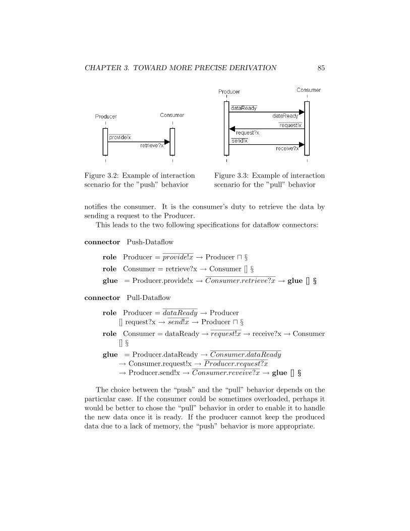
CHAPTER 3. TOWARD MORE PRECISE DERIVATION 85
Figure 3.2: Example of interactionscenario for the ”push” behavior
Figure 3.3: Example of interactionscenario for the ”pull” behavior
notifies the consumer. It is the consumer’s duty to retrieve the data bysending a request to the Producer.
This leads to the two following specifications for dataflow connectors:
connector Push-Dataflow
role Producer = provide!x → Producer u §role Consumer = retrieve?x → Consumer [] §glue = Producer.provide!x → Consumer.retrieve?x → glue [] §
connector Pull-Dataflow
role Producer = dataReady → Producer[] request?x → send!x → Producer u §
role Consumer = dataReady → request!x → receive?x → Consumer[] §
glue = Producer.dataReady → Consumer.dataReady→ Consumer.request!x → Producer.request?x→ Producer.send!x → Consumer.reveive?x → glue [] §
The choice between the “push” and the “pull” behavior depends on theparticular case. If the consumer could be sometimes overloaded, perhaps itwould be better to chose the “pull” behavior in order to enable it to handlethe new data once it is ready. If the producer cannot keep the produceddata due to a lack of memory, the “push” behavior is more appropriate.
CHAPTER 3. TOWARD MORE PRECISE DERIVATION 86
Components
Parts of components behavior are expressed in the architecture descriptionby the operations a component has to perform. The idea is to use as muchas possible this information so as to extract a global component behavior.A set of heuristics will be presented in order to derive the Wright specifi-cation of a component given its operations specifications in temporal logic.These heuristics result from an attempt to infer generalizations from con-crete examples. In fact, the system was first specified partially in Wrightand these heuristics are a tentative to structure the derivation process. Oneshould keep in mind that these are only heuristics and not proven correctrules. They nonetheless provide a useful help in the derivation of Wrightspecifications.
Heuristics are grouped into two main parts. First it is tried to trans-late a KAOS operation specification in Wright. Secondly the control flowis inferred so as to combine the different operations to obtain the full be-havior specification of the component. The presentation of each heuristicconsists of three parts. The first one explains in an intuitive way what isthe justification behind the heuristic. The second part defines the heuristicas formally as possible. Finally the third part applies the defined heuristicon examples coming from the power plant supervisory system specification.
Translating a individual operation
Pre-, post- and trigger conditions As explained in Section 1.1.2operations are defined in KAOS by a set of fields. The input/output fieldsdefine the object(s) received in parameters and modified by the operationrespectively, so defining the operation signature. Domain pre-/post condi-tions describe the elementary conditions on input and output states in thedomain. Required pre-/post conditions prescribe additional conditions oninput and output states that are necessary for ensuring some goals. Re-quired trigger conditions capture sufficient conditions on input state thatrequire the immediate application of the operation.
In Wright two constructs can be used to represent conditions: events, andconditions preceded by the when operator. As the when operator is used todescribe different behaviors depending on the truth value of some condition,it is only appropriate to express trigger and preconditions. Postconditionsare therefore always expressed by events. But what about preconditions?It depends. A precondition of an operation can also be a postcondition ofanother operation of the same component. In that case, the precondition

CHAPTER 3. TOWARD MORE PRECISE DERIVATION 87
will be expressed as an event. If it is not the case, two possibilities remain;either they are postconditions of an operation performed by another com-ponent or they are only preconditions of that particular operation. Theformer case implies some transmission from that other component to theconsidered component in order to notify the satisfaction of the condition.Otherwise the precondition will be forever false since the component willnot know the operation precondition has just become true. Who says trans-mission says there will be an event coming from one of the ports and theprecondition will thus be represented as an event. The latter case will beexpressed through the when operator. Classical situations include precon-ditions representing the state of an internal variable or some property ofthe environment. The preceding considerations can be summarized by thedefinitions of the following heuristics.
Heuristic 1 Let C be a component, Op1,. . . ,Opn be its operations.The postconditions (required or from the domain) of Op1,. . . ,Opn are ex-pressed in Wright by events.
Heuristic 2 Let C be a component, Op1,. . . ,Opn be its operations.The pre-(required or from the domain) and trigger conditions of Op1,. . . ,Opn
can be expressed either by events or by condition preceded by the when op-erator. Conditions preceded by when are used when the pre- or triggerconditions refer to the state of an internal variable or some property of theenvironment. Events are used otherwise.
These heuristics will now be illustrated with an example. Consideringthe operation SwitchSensorOff whose pre- and postconditions are givenby:
DomPre s.Status = onDomPost s.Status= offReqTrig ¬ s.WorkingProperly
The postcondition s.Status=Off will be expressed by the event TurnOff(s)as prescribed by heuristic 1. Both the pre- and the trigger conditions re-fer to the environment since the variable s denotes a sensor and Sensor isan environment agent. They will be therefore expressed by the conditions.Status=on ∧ ¬ s.WorkingkingProperly as said in heuristic 2.
Limitations of Wright regarding to temporal logic As Wrightdoes not support temporal logic there is an inevitable loss of semantic re-sulting from the translation of pre-, trigger and postconditions into Wright

CHAPTER 3. TOWARD MORE PRECISE DERIVATION 88
constructs. The time constraints will be in particular not translated. Nev-ertheless it is sometimes possible to be more restrictive than asked by thepre-, trigger and postconditions. Consider the typical example of boundedachieve goals expressed by A ⇒ ♦≤tsB that produces a trigger condition ofthe form ¬BSt−1sA ∧ ¬B. The trigger condition can be enforced to A sotransforming the goal in an immediate achieve instead of a bounded achieve.The operationalization looses in that case its minimality property but keepsits completeness and consistency.
Data transmission Data transmission is a particular case of the twopreceding heuristics since Wright has a dedicated construct for data trans-mission. As explained in Section 3.1 data can be associated to events via?d for a reception and !d for a transmission. In the abstract dataflow ar-chitecture, data transmissions are expressed through dataflow connectors.Assume that a dataflow connector links C1 and C2 via ports P1 and P2and transmits some data d from C1 to C2, there must be an event in thespecification of C1 specifying the sending of d and an event in the specifica-tion of C2 specifying the reception of d. This is expressed by the followingheuristic:
Heuristic 3 Let C1, C2 be two components linked by a dataflow connectorvia ports p1 and p2, let d be the transmitted data from C1 to C2. There mustbe an event e1 of the form p1.e1!d in the specification of C1 and an event e2
of the form p2.e2?d in the specification of C2.
Looking at the abstract dataflow architecture presented in Figure 2.11one can for example note the dataflow connector between the componentAcquisition Unit and Database carrying sensor information (si). Assum-ing that ToDB and FromAcq are the ports used by Acquisition Unitand DB to communicate, there will be an event ToDB.transmit!si and anevent FromAcq.receive?si in the specifications of Acquisition Unit andDB respectively.
Operations Once the various pre-, trigger and postconditions havebeen expressed by events or conditions in Wright, they have to be linked toform the operation. As pre- and trigger conditions precede postconditions,there should be a sequential order between them. The pre- and trigger con-ditions that are expressed by events are therefore linked to the correspondingpostconditions using→ in Wright. The pre- and trigger conditions expressedby a condition are added through the when operator. Note that in some

CHAPTER 3. TOWARD MORE PRECISE DERIVATION 89
case all the preconditions are expressed by events or by conditions. Conse-quently three cases should be distinguished:
1. all the pre- and trigger conditions are expressed by events
2. all the pre- and trigger conditions are expressed by conditions
3. the pre- and trigger conditions are expressed by events and conditions
Depending on the case the operation specification can be constructed asstated by the following heuristic:
Heuristic 4 Let Op be an operation. Let pre be the event expressing pre-and trigger conditions if there exists. Let cond be the condition expressingpreconditions if there exists. Let post be the event expressing postconditions.Depending on the case the Wright specification of the process representingOp is given by:
1. if all the pre- and trigger conditions are expressed by eventspre → post
2. if all the pre- and trigger conditions are expressed by conditionspost when cond
3. if the pre- and trigger conditions are expressed by events and conditionspre → post when cond
Wright allows to associate a process name with a process expression. Aprocess in Wright is an entity that can engage in events. Since at least thepostconditions of the operations are expressed by events, operations are thusprocesses. In order to make the mapping from the architecture descriptionresulting from the KAOS method as clear as possible processes correspond-ing to operations should be associated with the name of the operations.
Heuristic 5 Let Op be an operation.The process representation of Op in Wright should be associated with thename of Op.
Continuing with the example of SwitchSensorOff, its complete Wrightspecification can be derived using heuristic 4 and the resulting process canbe named SwitchSensorOff as advised by heuristic 5.
SwitchSensorOff = TurnOff(s) when s.Status=on∧ ¬ s.WorkingkingProperly

CHAPTER 3. TOWARD MORE PRECISE DERIVATION 90
Infering the control flow
Sequential Composition First in order to facilitate the followingexplanations two definitions are introduced: the global precondition andglobal postcondition. They formalize the fact that in order to perform anoperation, all its preconditions, be they required or from the domain, and atleast one of its trigger condition must hold. Similarly, once an operation hasbeen performed, all its postconditions, be they required or from the domain,must hold. The following definitions result from those considerations.
Definition 1 Let Op be an operation, DomPre1,. . . , DomPrem be its asso-ciate domain preconditions, ReqPre1,. . . , ReqPren be its associate requiredpreconditions and let ReqTrig1, . . . , ReqTrigp be its associate trigger con-ditions, DomPost1,. . . , DomPostq be its associate domain postconditions,ReqPost1,. . . , ReqPostr be its associate required postconditions.
DomPre(Op) =∧m
i=1 DomPrei
ReqPre(Op) =∧n
i=1 ReqPrei
Trig(Op) =∨p
i=1 ReqTrigi
DomPost(Op) =∧q
i=1 DomPostiReqPost(Op) =
∧ri=1 ReqPosti
Pre(Op) = DomPre(Op) ∧ReqPre(Op) ∧ Trig(Op)Post(Op) = DomPost(Op) ∧ReqPost(Op)
It will now be attempted to characterize the concept of sequentialitybetween two operations. Let C be a component, and Op1 and Op2 two of itsoperations. The question is: “Is there any relationship between Post(Op1)and Pre(Op2) that constraints Op1 to be applied before Op2?”. By definitionof Post(Op1) and Pre(Op2), Post(Op1) holds after the application of Op1
and Pre(Op2) must hold in order to apply Op2. Intuitively Post(Op1) ⊃Pre(Op2)1 appears directly as a condition since this formula states thatafter applying Op1, Pre(Op2) holds since Post(Op1) implies Pre(Op2) andOp2 can therefore be applied. However this is not the sole case where twooperations must be applied sequentially. Consider the following example:
Post(Op1) : x = 5Pre(Op2) : x = 5 ∧ y = 6
1⊃ will be used instead of the classical graphic notation for implication → to preventany confusion with the Wright operator
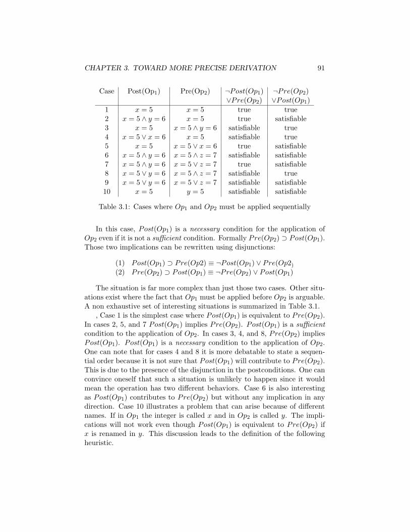
CHAPTER 3. TOWARD MORE PRECISE DERIVATION 91
Case Post(Op1) Pre(Op2) ¬Post(Op1) ¬Pre(Op2)∨Pre(Op2) ∨Post(Op1)
1 x = 5 x = 5 true true2 x = 5 ∧ y = 6 x = 5 true satisfiable3 x = 5 x = 5 ∧ y = 6 satisfiable true4 x = 5 ∨ x = 6 x = 5 satisfiable true5 x = 5 x = 5 ∨ x = 6 true satisfiable6 x = 5 ∧ y = 6 x = 5 ∧ z = 7 satisfiable satisfiable7 x = 5 ∧ y = 6 x = 5 ∨ z = 7 true satisfiable8 x = 5 ∨ y = 6 x = 5 ∧ z = 7 satisfiable true9 x = 5 ∨ y = 6 x = 5 ∨ z = 7 satisfiable satisfiable10 x = 5 y = 5 satisfiable satisfiable
Table 3.1: Cases where Op1 and Op2 must be applied sequentially
In this case, Post(Op1) is a necessary condition for the application ofOp2 even if it is not a sufficient condition. Formally Pre(Op2) ⊃ Post(Op1).Those two implications can be rewritten using disjunctions:
(1) Post(Op1) ⊃ Pre(Op2) ≡ ¬Post(Op1) ∨ Pre(Op2)
(2) Pre(Op2) ⊃ Post(Op1) ≡ ¬Pre(Op2) ∨ Post(Op1)
The situation is far more complex than just those two cases. Other situ-ations exist where the fact that Op1 must be applied before Op2 is arguable.A non exhaustive set of interesting situations is summarized in Table 3.1.
, Case 1 is the simplest case where Post(Op1) is equivalent to Pre(Op2).In cases 2, 5, and 7 Post(Op1) implies Pre(Op2). Post(Op1) is a sufficientcondition to the application of Op2. In cases 3, 4, and 8, Pre(Op2) impliesPost(Op1). Post(Op1) is a necessary condition to the application of Op2.One can note that for cases 4 and 8 it is more debatable to state a sequen-tial order because it is not sure that Post(Op1) will contribute to Pre(Op2).This is due to the presence of the disjunction in the postconditions. One canconvince oneself that such a situation is unlikely to happen since it wouldmean the operation has two different behaviors. Case 6 is also interestingas Post(Op1) contributes to Pre(Op2) but without any implication in anydirection. Case 10 illustrates a problem that can arise because of differentnames. If in Op1 the integer is called x and in Op2 is called y. The impli-cations will not work even though Post(Op1) is equivalent to Pre(Op2) ifx is renamed in y. This discussion leads to the definition of the followingheuristic.
CHAPTER 3. TOWARD MORE PRECISE DERIVATION 92
Heuristic 6 Let C be a component, Op1, Op2 be two of its operations. As-suming that Post(Op1) and Pre(Op2) are not equal to the constant true orfalse. Op1 application precedes Op2 application if there exists a renaming ofvariables such as
Post(Op1) ⊃ Pre(Op2) or Pre(Op2) ⊃ Post(Op1)
Two things should be kept in mind: first the heuristic does not say thatapplication of Op2 takes place straight after Op1 application but only thatOp2 follows Op1 application without saying anything about when exactlyOp2 is applied; secondly other operations can have to be performed sequen-tially; the heuristic is not exhaustive.
To illustrate this heuristic, the operation SwitchSensorOff already dis-cussed and its dual operation SwitchSensorOn will be examined. Theirpre-, trigger and postconditions are given by:
Operation SwitchSensorOffDomPre s.Status = onDomPost s.Status= offReqTrig ¬ s.WorkingProperly
Operation SwitchSensorOnDomPre s.Status = offDomPost s.Status= onReqPre s.WorkingProperly
One can note that Pre(SwitchSensorOn) ⊃ Post(SwitchSensorOff) andthat Pre(SwitchSensorOff) ⊃ Post(SwitchSensorOn). Heuristic 6 thereforeprescribes that there is a sequential order between the two operations wichis logical since to turn a sensor off it has to be turned on before and viceversa. One can also note that although there is a sequential order, the twooperations do not have to be successive. Indeed other operations can slot intheir application.
Direct sequential composition The next heuristic goes further im-posing a direct succession between two operations. The heuristic bases onthe milestone pattern for goal refinement. It prescribes that some milestonestates are mandatory in order to reach the final one, that is, it imposes thatthe milestone state precedes the final state. The intermediate goals thispattern produces are Achieve goals. These can be operationalized by thebounded achieve pattern. The two resulting operations must therefore beexecuted sequentially. The two patterns are presented in Figure 3.4.
One can note interesting characteristics. DomPost(Op1) is a necessarycondition to Trig(Op2), that is, Trig(Op2) ⊃ �DomPost(Op1)2. It is thus
2the � operator is needed because the ASB operator implies that A has been true but
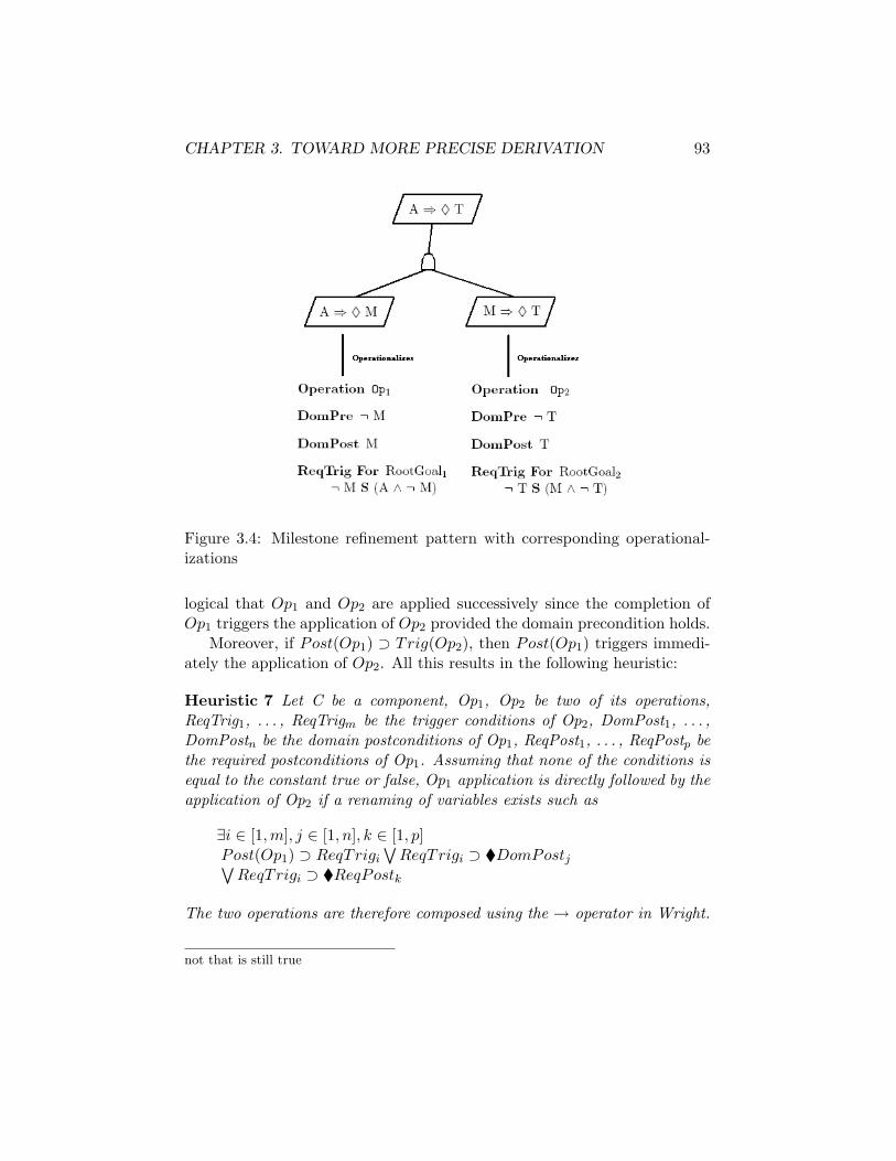
CHAPTER 3. TOWARD MORE PRECISE DERIVATION 93
Figure 3.4: Milestone refinement pattern with corresponding operational-izations
logical that Op1 and Op2 are applied successively since the completion ofOp1 triggers the application of Op2 provided the domain precondition holds.
Moreover, if Post(Op1) ⊃ Trig(Op2), then Post(Op1) triggers immedi-ately the application of Op2. All this results in the following heuristic:
Heuristic 7 Let C be a component, Op1, Op2 be two of its operations,ReqTrig1, . . . , ReqTrigm be the trigger conditions of Op2, DomPost1, . . . ,DomPostn be the domain postconditions of Op1, ReqPost1, . . . , ReqPostp bethe required postconditions of Op1. Assuming that none of the conditions isequal to the constant true or false, Op1 application is directly followed by theapplication of Op2 if a renaming of variables exists such as
∃i ∈ [1,m], j ∈ [1, n], k ∈ [1, p]Post(Op1) ⊃ ReqTrigi
∨ReqTrigi ⊃ �DomPostj∨
ReqTrigi ⊃ �ReqPostk
The two operations are therefore composed using the → operator in Wright.
not that is still true

CHAPTER 3. TOWARD MORE PRECISE DERIVATION 94
As an example of the application of this heuristic, consider the two oper-ations RaiseAlarm and SwitchAlarmStatusOn performed by ALARM. Theirsimplified specification is given by:
Operation RaiseAlarmDomPre ¬ Raise(fi,a)DomPost Raise(fi,a)ReqTrig @ Transmitted(fi,PRECON,ALARM)
Operation SwitchAlarmStatusOnDomPre powerPlant.AlarmStatus = offDomPost powerPlant.AlarmStatus= onReqTrig Raise(fi,a)
As DomPost(RaiseAlarm) ⊃ ReqTrig(SwitchAlarmStatusOn) the twooperations must be applied successively as prescribed by heuristic 7.
Parallel composition The preceding heuristic defines a mean to linktwo successive operations but not how to compose the others, be they se-quentially related or not. The remaining operators to compose operations inWright are u, [], ‖. Different choices will result in different behaviors. How-ever one must pay attention to certain important considerations. When twooperations are composed using the ‖ operator, they are executed in paralleland parallelism can lead to race conditions. Race conditions occur when twooperations try to update the same data at the same time. Although Wrightenables their detection, it might be better to ensure their absence by con-struction. That is why the use of the parallel composition operator betweentwo operations is advocated only provided their Output field is different.Moreover operations that are linked sequentially, be they successive or not,cannot be executed in parallel. This leads to the following definition andheuristic.
Definition 2 Let Op be an operation, Obj1, . . . , Objn the objects presentin its output field., the set of objects updated by Op is defined by:
Update(Op)={Obj1, . . . , Objn}
Heuristic 8 Let Op1 and 0p2 be two operations such as Op1 must not pre-cede Op2 and Op2 must not precede Op1. Op1 and Op2 can be composedusing the parallel composition operator (‖) in Wright only if:
Update(Op1) ∩ Update(0p2) = ∅

CHAPTER 3. TOWARD MORE PRECISE DERIVATION 95
Variable application order For the remaining operations, the choicebetween [] and u is essentially guided by the semantic associated to thoseoperators. If at least one of their preconditions refers to the environment,for example because the transmission of some data from another componentis needed, then the [] operator is used. If no precondition refers to theenvironment, then the u. This is expressed by the following heuristic:
Heuristic 9 Let Op1 and 0p2 be two operations such as Op1 and Op2 arenot successive operations and cannot be executed in parallel. Op1 is composedwith Op2 using the [] operator in Wright if at least one of their preconditionsrefers to the environment, otherwise the u operator is used.
Let’s come back to the two operations SwitchSensorOff and Switch-SensorOn. It has been discussed that they are linked by a sequential orderbut no operator linking them has been imposed so far. Since their precondi-tion typically refer to the environment through Sensor, the [] operator will beused to compose them. The specification resulting from their compositionis given by:
SwitchSensorOff [] SwitchSensorOn whereSwitchSensorOff = TurnOff(s) when s.Status=on
∧ ¬ s.WorkingkingProperlySwitchSensorOn = TurnOn(s) when s.Status=off
∧ s.WorkingkingProperly
3.2.4 Elaboration of Scenarios
An important by-product of the Wright description is the ability to gener-ate scenarios. An animator for CSP (ProBE) can be used to visualize thebehavior of the architectural Wright specification. Of course from a singleWright specification a lot of scenarios can be generated due to the presenceof the different components running in parallel. Even within a component,the behavior can lead to many different scenarios because of the presenceof a choice operator (u or []) for example. The scenarios so elaborated canbe compared with the ones envisioned during requirements analysis to see ifthey match. This could be used to validate the architecture with respect toits functional requirements and to detect faults in the translation to Wright.Depending on the case the requirements or the architecture could be cor-rected. This outlines that the different phases of the software developmentprocess are interwoven and that this process is iterative rather than sequen-tial.

CHAPTER 3. TOWARD MORE PRECISE DERIVATION 96
3.3 Application to the Power Plant System
This section aims at illustrating the derivation from the abstract dataflowarchitecture to a Wright description using the various techniques presentedin Section 3.2. The Wright specification will be elaborated step by step inorder to highlight how the different heuristics can be applied. For briefnesspurpose, only the fragment of the architecture dealing with PRECON andALARM will be examined as presented in Figure 3.5.
Figure 3.5: Fragment of the dataflow architecture containing PRECON andALARM
From the graphical representation a first draft of the Wright specificationcan be very easily obtained according to what has been explained in Section3.2.2. The resulting Wright specification is:
configuration PRECON-ALARM
component PRECON
port ALARMOutput
component ALARM
port PRECONInput
connector Dataflow
role Producerrole Consumer
instances Precon: PRECONAlarm: ALARMPrecon2Alarm: Dataflow

CHAPTER 3. TOWARD MORE PRECISE DERIVATION 97
Attachements Precon.ALARMOutput as Precon2Alarm.ProducerALARM.PRECONInput as Precon2Alarm.Consumer
end PRECON-ALARM
Once the basic structure in place, the type of dataflow connector canbe chosen. Since ALARM can be busy with the management of an alarm,the pull-dataflow is selected. So doing ALARM will only ask for informationon fault when it will be ready to handle them. The specification of thepull-dataflow connector is given in Section 3.2.3.
The specification of the PRECON and ALARM behavior can now be derived.PRECON will be considered first. It has to perform the following operations:
1. Calculate
2. DetectFault
3. SwitchFaultStatusOn
4. SwitchFaultSTatusOff
Consider the first operation: Calculate. Its KAOS specification is givenby:
Operation Calculate
Input si: SensorInformation
Output /
DomPre ¬ CalculationDone
DomPost CalculationDone
ReqTrig For CalculationDone¬ CalculationDone S=1s Transmitted(si,DB,PRECON) ∧ ¬ Cal-culationDone
PerformedBy PRECON
Heuristic 1 states that postconditions are expressed through events. Theevent CalculationDone is so created. Figure 3.5 shows that there is adataflow connector between Acquisition Unit and PRECON carrying sen-sor information. Heuristic 3 states there must be an event e of the forme?si in PRECON Wright specification. Moreover heuristic 2 states that the
CHAPTER 3. TOWARD MORE PRECISE DERIVATION 98
trigger conditions can be expressed by events. The required trigger condi-tion is thereby expressed by the event AcquisitionInput.receive?si. Oneshould note two things: first the formalization of the operation states theinformation on sensors have to be transmitted from DB to PRECON and notfrom Acquisition Unit, secondly the event does not exactly express all thetrigger conditions.
This first problem has already been discussed in Section 2.3.1. It isbecause the dataflow architecture derived does not always reflect the actualdataflow. The problem is therefore not from the heuristics but from theabstract dataflow architecture itself. For this reason it will next be assumedthat sensor information are transmitted from Acquisition unit.
The second problem arises from the fact that Wright does not supporttemporal constraint specification. Part of the information is consequentlylost.
The application of heuristic 4 enables to link the events representingthe trigger and postconditions of Calculate by the → operator in orderto build the operation specification. In accordance with heuristic 5 theassociate process has Calculate as name. From there a first draft of PRECONspecification can be constructed:
component PRECON
port AcquisitionInput = receive?si → AcquisitionInput
port ALARMOutput = . . .
computation = Calculate . . .whereCalculate = AcquisitionInput.receive?si → calculationDone
Consider now the second operation DetecFault whose KAOS specifica-tion is:
Operation DetectFault
Input f: Fault, l: Location
Output /
DomPre ¬ Detected(f,l)
DomPost Detected(f,l)
ReqTrig For FaultDetectedWhenCalculationDone¬Detected(f,l) S=1s CalculationDone ∧Occurs(f,l) ∧ ¬Detected(f,l)
PerformedBy PRECON

CHAPTER 3. TOWARD MORE PRECISE DERIVATION 99
Comparing the trigger condition of Calculate and the postcondition ofCalculate one can note that heuristic 7 applies in this case since
¬ Detected(f,l) S=1s CalculationDone ∧ Occurs(f,l) ∧ ¬ Detected(f,l)⊃ � CalculationDone
DetectFault should therefore be applied directly after Calculate. Apart of the trigger condition DetectFault matches the postcondition ofCalculate and will therefore be expressed by the same event. Heuristic2 applies to Occurs(f, l) since it is clearly a property of the environment.Occurs(f,l) will thus be expressed by a condition using the when operator.Heuristic 1 enables to express the postcondition Detected(f, l) as an event.Note that since the pull dataflow connector has been chosen, the event ofdetect a fault corresponds to the DataReady event of the connector. In fact,the interaction between PRECON and ALARM is structured as follows: whenPRECON detects a fault, it notifies ALARM that will subsequently ask for thecorresponding fault information. The event Detected(f, l) has therefore tobe sent on the port AlarmOutput. Heuristics 4 and 5 allow to complete thespecification. The specification of PRECON can be rewritten as follows withthe added operation:
component PRECON
port AcquisitionInput = receive?si → AcquisitionInput
port ALARMOutput = ALARMOutput.Detected(f, l)
computation = Calculate where
Calculate ={
AcquisitionInput.receive?si → calculationDone→ DetectFault
DetecFault ={
ALARMOutput.Detected(f, l) → . . . whenOccurs(f, l)computation when¬Occurs(f, l)
Since the two following operations – SwitchFaultStatusOn and Switch-FaultStatusOff are very similar they will be handled simultaneously. Theirspecicification is given by:
Operation SwitchFaultStatusOn
Input f: Fault, l: Location, PowerPlant
Output PowerPlant/FaultStatus
DomPre PowerPlant.FaultStatus = off
DomPost PowerPlant.FaultStatus =on
ReqTrig For FaultStatusUpdatedDetected(f,l)
Operation SwitchFaultStatusOff
Input f: Fault, l: Location, PowerPlant
Output PowerPlant/FaultStatus
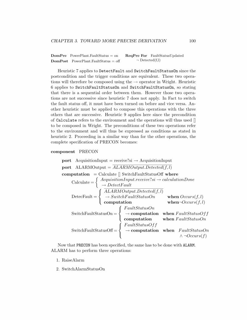
CHAPTER 3. TOWARD MORE PRECISE DERIVATION 100
DomPre PowerPlant.FaultStatus = on
DomPost PowerPlant.FaultStatus = off
ReqPre For FaultStatusUpdated¬ Detected(f,l)
Heuristic 7 applies to DetectFault and SwitchFaultStatusOn since thepostcondition and the trigger conditions are equivalent. These two opera-tions will therefore be composed using the → operator in Wright. Heuristic6 applies to SwitchFaultStatusOn and SwitchFaultStatusOn, so statingthat there is a sequential order between them. However those two opera-tions are not successive since heuristic 7 does not apply. In Fact to switchthe fault status off, it must have been turned on before and vice versa. An-other heuristic must be applied to compose this operations with the threeothers that are successive. Heuristic 9 applies here since the preconditionof Calculate refers to the environment and the operations will thus used []to be composed in Wright. The preconditions of these two operations referto the environment and will thus be expressed as conditions as stated inheuristic 2. Proceeding in a similar way than for the other operations, thecomplete specification of PRECON becomes:
component PRECON
port AcquisitionInput = receive?si → AcquisitionInput
port ALARMOutput = ALARMOutput.Detected(f, l)
computation = Calculate [] SwitchFaultStatusOff where
Calculate ={
AcquisitionInput.receive?si → calculationDone→ DetectFault
DetecFault =
ALARMOutput.Detected(f, l)→ SwitchFaultStatusOn when Occurs(f, l)computation when¬Occurs(f, l)
SwitchFaultStatusOn =
FaultStatusOn→ computation when FaultStatusOffcomputation when FaultStatusOn
SwitchFaultStatusOff =
FaultStatusOff→ computation when FaultStatusOn
∧ ¬Occurs(f)
Now that PRECON has been specified, the same has to be done with ALARM.ALARM has to perform three operations:
1. RaiseAlarm
2. SwitchAlarmStatusOn
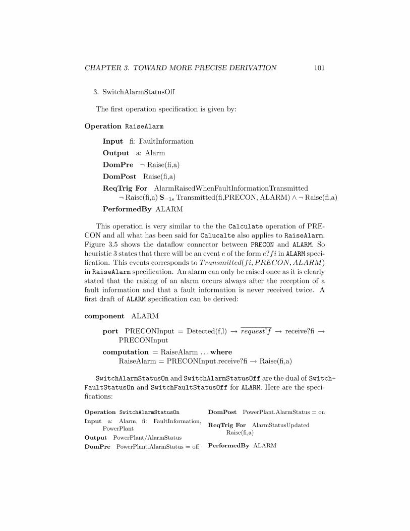
CHAPTER 3. TOWARD MORE PRECISE DERIVATION 101
3. SwitchAlarmStatusOff
The first operation specification is given by:
Operation RaiseAlarm
Input fi: FaultInformation
Output a: Alarm
DomPre ¬ Raise(fi,a)
DomPost Raise(fi,a)
ReqTrig For AlarmRaisedWhenFaultInformationTransmitted¬ Raise(fi,a) S=1s Transmitted(fi,PRECON, ALARM) ∧ ¬ Raise(fi,a)
PerformedBy ALARM
This operation is very similar to the the Calculate operation of PRE-CON and all what has been said for Calucalte also applies to RaiseAlarm.Figure 3.5 shows the dataflow connector between PRECON and ALARM. Soheuristic 3 states that there will be an event e of the form e?fi in ALARM speci-fication. This events corresponds to Transmitted(fi, PRECON,ALARM)in RaiseAlarm specification. An alarm can only be raised once as it is clearlystated that the raising of an alarm occurs always after the reception of afault information and that a fault information is never received twice. Afirst draft of ALARM specification can be derived:
component ALARM
port PRECONInput = Detected(f,l) → request!f → receive?fi →PRECONInput
computation = RaiseAlarm . . .whereRaiseAlarm = PRECONInput.receive?fi → Raise(fi,a)
SwitchAlarmStatusOn and SwitchAlarmStatusOff are the dual of Switch-FaultStatusOn and SwitchFaultStatusOff for ALARM. Here are the speci-fications:
Operation SwitchAlarmStatusOn
Input a: Alarm, fi: FaultInformation,PowerPlant
Output PowerPlant/AlarmStatus
DomPre PowerPlant.AlarmStatus = off
DomPost PowerPlant.AlarmStatus = on
ReqTrig For AlarmStatusUpdatedRaise(fi,a)
PerformedBy ALARM
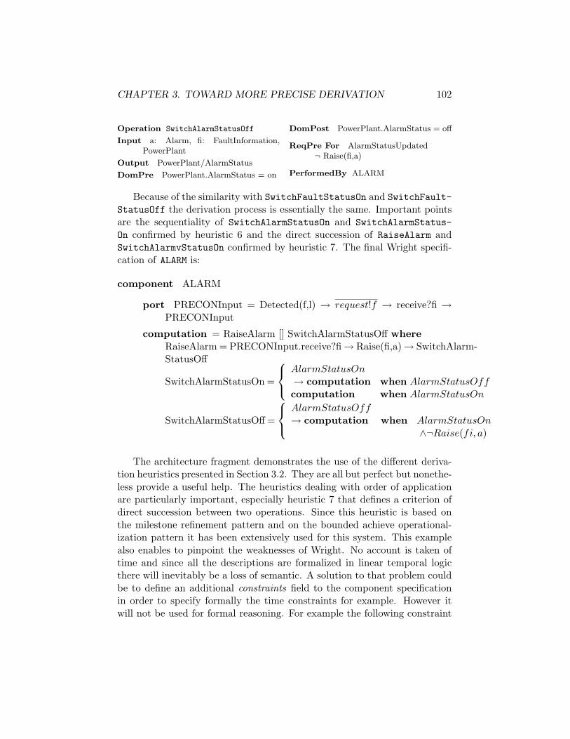
CHAPTER 3. TOWARD MORE PRECISE DERIVATION 102
Operation SwitchAlarmStatusOff
Input a: Alarm, fi: FaultInformation,PowerPlant
Output PowerPlant/AlarmStatus
DomPre PowerPlant.AlarmStatus = on
DomPost PowerPlant.AlarmStatus = off
ReqPre For AlarmStatusUpdated¬ Raise(fi,a)
PerformedBy ALARM
Because of the similarity with SwitchFaultStatusOn and SwitchFault-StatusOff the derivation process is essentially the same. Important pointsare the sequentiality of SwitchAlarmStatusOn and SwitchAlarmStatus-On confirmed by heuristic 6 and the direct succession of RaiseAlarm andSwitchAlarmvStatusOn confirmed by heuristic 7. The final Wright specifi-cation of ALARM is:
component ALARM
port PRECONInput = Detected(f,l) → request!f → receive?fi →PRECONInput
computation = RaiseAlarm [] SwitchAlarmStatusOff whereRaiseAlarm = PRECONInput.receive?fi→ Raise(fi,a)→ SwitchAlarm-StatusOff
SwitchAlarmStatusOn =
AlarmStatusOn→ computation when AlarmStatusOffcomputation when AlarmStatusOn
SwitchAlarmStatusOff =
AlarmStatusOff→ computation when AlarmStatusOn
∧¬Raise(fi, a)
The architecture fragment demonstrates the use of the different deriva-tion heuristics presented in Section 3.2. They are all but perfect but nonethe-less provide a useful help. The heuristics dealing with order of applicationare particularly important, especially heuristic 7 that defines a criterion ofdirect succession between two operations. Since this heuristic is based onthe milestone refinement pattern and on the bounded achieve operational-ization pattern it has been extensively used for this system. This examplealso enables to pinpoint the weaknesses of Wright. No account is taken oftime and since all the descriptions are formalized in linear temporal logicthere will inevitably be a loss of semantic. A solution to that problem couldbe to define an additional constraints field to the component specificationin order to specify formally the time constraints for example. However itwill not be used for formal reasoning. For example the following constraint

CHAPTER 3. TOWARD MORE PRECISE DERIVATION 103
can be added to component ALARM to state that an alarm has to be raisedwithin one second after the reception of the fault information.
constraints ∀ fi:FaultInformation, ∃ !a:AlarmTransmitted(fi,PRECON,ALARM) ⇒ ♦≤1s Raise(fi,a)
3.4 Making Architectural Patterns Further Pre-cise
The description of pattern has been identified as a weak point in the KAOSmethod. This section aims at correcting part of this weakness. Wright willbe used to describe precisely the structural and behavioral effects of patternapplication. Two patterns are studied: the fault-tolerant communicationpattern and the observer pattern, as they are the only applied to the powerplant supervisory system. This allows the validation of the pattern descrip-tion on a real example although the intent of the description is to be generaland applicable to any system.
3.4.1 The Fault-Tolerant Communication Pattern
General Considerations on Fault Tolerance
The aim of this work is certainly not to focus on fault tolerance but somenotions are nevertheless useful. This subsection will explain the foundationsof fault-tolerant distributed computing and set up the underlying model andhypotheses used further. The interested reader can find a summary in [17].
Fault tolerance aims at making distributed systems more reliable byhandling faults in complex computing environments. There is now an in-creasing demand for dependable systems, i.e., systems with quantifiable re-liability properties. This is particularly true in safety and security-criticalapplications.
The underlying model used for fault tolerance is the asynchronous systemmodel. A distributed system is asynchronous if there is no bound on messagedelay, clock drift, or the time necessary to execute a step. So no timeassumptions will be made whatsoever.
It is also important to clearly state what kind of faults will be tolerated bythe pattern. Faults are traditionally grouped in fault classes or fault models.Well-known examples are the crash failure model (in which processors simplystop executing at a specific point in time) or Byzantine (in which processors

CHAPTER 3. TOWARD MORE PRECISE DERIVATION 104
may behave in arbitrary, even malevolent, ways). The faults handled by thepattern belong to the crash failure model.
Systems are characterized by two major properties: safety and liveness.Informally, the safety property states that some specific “bad thing” neverhappens. It describes the set of “legal” system configurations, i.e, the invari-ant. The liveness property claims that some “good thing” will eventuallyhappen during system execution. A common example of liveness is termi-nation. For formal definitions, please refer to [17].
Different forms of Fault-Tolerance have been defined according to howthe safety and liveness properties of the distributed system hold over timein the presence of faults. If a program A still satisfies both its safety andliveness properties in the presence of faults from a specified fault class F,then it is said that A is masking fault tolerant for fault class F. This is thestrictest, most costly and most desirable form of fault tolerance because theprogram is able to tolerate the faults transparently. This is the form of faulttolerance this pattern will achieve. The other forms of fault tolerance aresummarized in Table 3.23.
live not livesafe masking fail safenot safe nonmasking none
Table 3.2: Four Forms of Fault Tolerance
The notion of redundancy is omnipresent in the field of fault toleranceand it arises for a simple reason: redundancy is a necessary condition to faulttolerance. Two forms of redundancy can be distinguished, namely in spaceand in time. Redundancy in space refers to the superfluous part of the stateof a system, i.e., states never reached when faults do not occur. It is usuallyachieved by supplying a component more than once. It will be the case inthis pattern. Redundancy in time refers to superfluous state transitions ofa system, i.e., the superfluous work it performs. Practical examples includeroll-back recovery or reset procedures. Considering the fault handled by thepattern – process crash – the second one will be used.
Pattern description
Introduction The aim of the pattern is to achieve masking fault-tolerance,i.e., preserve safety and liveness. The pattern will proceed in a stepwise
3live means satisfying the liveness property and safe means satisfying the safety propery
CHAPTER 3. TOWARD MORE PRECISE DERIVATION 105
manner, achieving first nonmasking fault tolerance and then masking faulttolerance. This approach is similar to the one described in [3].
The first stage will transform an intolerant component into a nonmaskingone. The fault class considered here is the process crash. Ensuring livenessfor a certain fault class means that when a fault of that class occurs thecomponent will eventually recover from this fault. So, the pattern has toensure that in case of a process crash the process will be restarted. This isthe correction phase.
The second stage will make component masking tolerant. The aim ofthis transformation is to ensure safety, i.e., preventing the violation of theinvariant. This can only be done via the fault detection, i.e., the detectionphase.
Important remarks have to been made at this point. Due to the underly-ing model – the asynchronous system model – the problem of the detectionof a process crash cannot be solved deterministically. Intuitively, it is be-cause it is impossible to determine whether a process has actually crashedor is only “very slow”.
Various approaches have been used to solve this problem. Chandra andToueg [7] proposed to use what they called unreliable failure detectors, a de-tection mechanism that can make mistakes. An alternative approach, takenby the Isis team [25], is based on the assumption that failure detectors rarelymake mistakes. In those cases where a correct process p is falsely suspectedby the failure detector, p is effectively forced “to crash”. The detector forcesthe system to conform to its view. From the application’s point of view, thisfailure detector looks perfect. This is the approach followed here.
One will concentrate on abstract concepts rather than giving some spe-cific implementations. The purpose is indeed to help the programmer butnot to substitute to him.
Description A first glance of the pattern is presented in Figure 3.6. Aspreviously mentioned, the pattern application encompasses two phases, cor-rection and detection. Each of them will be described further.
Stage 1: Correction phase The aim of this phase is to correct theoccurring faults. To do so, a mechanism of recovery should be introduced.As the fault considered in this case are process crashes, the designated mech-anism is naturally reset procedures. However the problem with reset proce-dures is the time it takes. Some systems can not afford any delay especiallywhen some time constraints have to be ensured. It is so desirable that the

CHAPTER 3. TOWARD MORE PRECISE DERIVATION 106
Figure 3.6: Fault-tolerant communication pattern
system goes on with working without any delay. To this end a copy of thecomponent is introduced. Whenever a process crashes, its copy should takeon its role. It is important that only one component should be working ata time. After a process has been reset it remains inactive until its copycrashes.
The resulting system has so the following properties.
1. Introduction of reset proceduresA reset mechanism should be introduced to restart any componentthat may have crashed.
2. Introduction of copies of componentsAn exact copy of the components between which the communicationhas to become fault-tolerant is added to the system. The two copieshave exactly the same capabilities, i.e, the same specifications in termsof their ADL descriptions.
3. Switch in case of failureWhen, for whatever reasons, a component goes down, its copy shouldtake on its role. This change of operating component should not resultneither in any error of treatments nor in any loss of information. Thecrashed component should also be reset.
4. One at a timeIn order to avoid duplicate treatments and so on, only one of the twocopies should work at a time.
Let’s try now to introduce transformations to generics ADL componentspecifications to ensure those four properties.
First a reset mechanism has to be added to components. This is not assimple as it seems. If a process has crashed, it will not reply to any solicita-tion from the outside. In fact what should be done is killing the process and

CHAPTER 3. TOWARD MORE PRECISE DERIVATION 107
restart it. This leads to some difficulties. The connectors through whichthe process communicates have to remain active in order not to disturbthe surrounding processes. Moreover once the process restarted it shouldcommunicate through those connectors. In an aim of simplicity it will beconsidered that some reset procedure exists and works even if the processhas crashed saving to deal with all the implementation aspects. The speci-fications can be modified as followed.
component C
port . . .
computation = compute
component newC
port . . .
computation = compute [] reset → computation
The introduction of copies is straightforward. As the specifications ofthe two copies are strictly equal, an extra instance of the component hassimply to be added.
instances x: C1y: C2
instances x1, x2: C1y1, y2: C2
The last two properties are tightly linked and so will be the transforma-tions introduced on the system. In order to have two copies of C1 and C2and if only one copy can operate at a time, the state of the component mustbe stored in some way in the component specification. A component can beeither passive or active. This will be modeled by adding two external eventsto which the component will react. Those two events are simply wakeUpand sleep. A component should never be placed in an inactive state if it didnot crash before. So this change of state should take place after the resetprocedure. The modification can be generalized as follows. The followingmodification simply states that either the component operates normally or,after crashing, it receives a sleep event and will not go on with its dutyunless it receives a wakeUp event.
component C
CHAPTER 3. TOWARD MORE PRECISE DERIVATION 108
port . . .
computation = compute [] reset → computation
component newC
port . . .
computation = compute [] reset→ sleep→ wakeUp→ computation
Afterward it should be ensured that the switch in active component onlytakes place in case of failure, that any crashed component will be reset andthat only one copy is working at a time. So to say, the failure should firstbe corrected and that correction should not be visible to the surroundingcomponents. The inherent problem of restarting a component is that ittakes time and that time delay might not be affordable. As soon as thereset procedure has been called on the crashed component, its copy shouldbe made active. So the failure triggers first the reset of the component andthen the change of active component. Once the crashed component reset itreceives a sleep signal signifying that it is now the inactive component. Onecould suggest to first wake up the safe component before restarting the otherone. But resulting from the asynchronous nature of the underlying model, itis impossible to detect whether or not a component has crashed. Doing thatit would be possible to have both copies of the components working at thesame time. Resulting from those considerations, a preliminary definition ofthe connector linking the two copies can be introduced.
connector copyConnect
role Copy1,2
glue = (Copy1.failure → Copy1.reset → Copy2.wakeUp → Copy1.sleep)[](Copy2.failure → Copy2.reset → Copy1.wakeUp → Copy2.sleep)
With these transformations the four properties stated above hold. Thiscompletes the first stage of the method – the corrective one.
Stage 2: Detection phase Now that correction mechanisms havebeen introduced, mechanisms to detect the occurrence of faults need tobe defined. One should remember that the problem of detecting processcrashes cannot be solved deterministically. This impossibility results fromthe inherent difficulty of determining whether a system has actually crashedor is only “very slow”. The chosen approach to solve this problem is to

CHAPTER 3. TOWARD MORE PRECISE DERIVATION 109
force any suspected process to reset, based on the assumption that the faultdetector rarely makes mistakes. The suspicion of a process will be based ontime-outs. The choice of an adequate time-out value is of great importancefor the global performance of the system. The value should not be too smallto prevent any working process from resetting unnecessarily while it shouldnot be too long in order not to slow down all the system when a process haseffectively crashed.
Two main properties must be achieved in this phase. First faults have tobe detected and secondly all what has been made so far must be transparentfor all the surrounding components. They should not be aware neither ofthe presence of two copy components nor of any process crash nor of anyswitch in active components .
A third one states there can be no precedence between the two copies ofa component.
Those properties can be summarized as followed.
1. Introduction of fault detection mechanismA mechanism to detect process crashes should be added. One shouldnote that this detection mechanism could suspect correctly workingprocesses.
2. No precedence between the two copiesThere is no master and slave component. The two copies are exactlyequal. This equality results in the following policy: the switch ofoperating component occurs only in case of failure. When a componentrecovers from a failure it becomes inactive.
3. Transparency of switching The switch in the operating componentshould be done in a completely transparent way to other interact-ing components. They should not even notice that a switch occurred.Moreover the surrounding components should not be aware of the pres-ence of duplicate copies of the component they interact with.
As in the previous subsection, those properties will be translated in termsof concrete transformations to apply to the ADL description of components.
The introduction of a fault detection mechanism leads to some problems.As previously mentioned the classic solution consists of sending messages tothe processes and if they do not answer within a certain time-out value theyare suspected of having crashed. The difficulty arises from the fact thatWright does not support such time constraints. However it is possible tospecify it using the when operator in a very understandable way. First the
CHAPTER 3. TOWARD MORE PRECISE DERIVATION 110
connector between the two copies has to send the message to the copies.Second some answering procedure should be added to the components tosay “Yes I’m alive”. The modified specifications are given below:
connector copyConnect
role Copy1,2
glue = Copy1
Copy1 = Copy1.isAlive →{
Copy1 when Copy1.ImAlive within t sCopy1Failure when ¬Copy1.ImAlive within t s
Copy2 = Copy2.isAlive →{
Copy2 when Copy2.ImAlive within t sCopy2Failure when ¬Copy2.ImAlive within t s
Copy1Failure ={
Copy1.reset → Copy2.wakeUp
→ Copy1.sleep → Copy2
Copy2Failure ={
Copy2.reset → Copy1.wakeUp
→ Copy2.sleep → Copy1
component newC
port Copylink={
isAlive → ImAlive → Copylink[] reset → sleep → wakeUp → Copylink
computation =
compute[] reset → sleep → wakeUp → computation[] Copylink.isAlive → Copylink.ImAlive → computation
One can note in the previous specification it has been arbitrarily specifiedthat Copy1 is the first to be active. As both copies are strictly equivalentthis does not invalidate the no precedence policy between the copies.
When considering transparency, things are getting far more complicated.Transparency means that first every component interacting with a “double”component should not even notice this fact and secondly the switch in op-erating component should also not be noticed. The solution adopted is a“forked” connector. In fact all the interaction with a “double” componentwill be made with the two at the same time, as it was previously ensured onlyone will respond as the other will be asleep. It could appear a bit strangebut it is in fact a simple and practical solution. For the components it isexactly the same situation as before. They just do not know that they usenow a “forked” connector. Of course the specification of the role of the con-nectors can not change otherwise it will be visible to the component becausethe role has to be compatible with the port to have a working specification.
CHAPTER 3. TOWARD MORE PRECISE DERIVATION 111
So only the glue will be modified. So two new kinds of connectors will beintroduced. A right-forked connector for the components interacting with a“double” component that are not “doubled” themselves, a left-forked for thedouble components interacting with a single component and a double-forkedconnector to link two “double” components. The modified connectors aredefined as follows:
connector oldConnect
role r1
role r2
glue = r1.eventA → r2.eventB → . . .→ glue
connector right-forked
role r1
role Copy1
role Copy2
glue = r1.eventA → (Copy1.eventB ‖ Copy2.eventB) → . . .→ glue
connector left-forked
role r1
role Copy1
role Copy2
glue = (r1Copy1.eventA [] r1Copy2.eventA) → r2.eventB → . . .→glue
connector double-forked
role r1Copy1
role r1Copy2
role r2Copy1
role r2Copy2
glue = (r1Copy1.eventA [] r1Copy2.eventA) → (r2Copy1.eventB ‖r2Copy2.eventB) → . . .→ glue
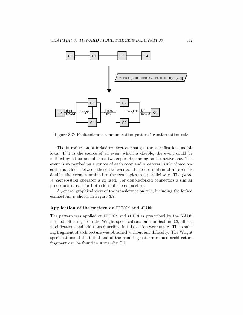
CHAPTER 3. TOWARD MORE PRECISE DERIVATION 112
Figure 3.7: Fault-tolerant communication pattern Transformation rule
The introduction of forked connectors changes the specifications as fol-lows. If it is the source of an event which is double, the event could benotified by either one of those two copies depending on the active one. Theevent is so marked as a source of each copy and a deterministic choice op-erator is added between those two events. If the destination of an event isdouble, the event is notified to the two copies in a parallel way. The paral-lel composition operator is so used. For double-forked connectors a similarprocedure is used for both sides of the connectors.
A general graphical view of the transformation rule, including the forkedconnectors, is shown in Figure 3.7.
Application of the pattern on PRECON and ALARM
The pattern was applied on PRECON and ALARM as prescribed by the KAOSmethod. Starting from the Wright specifications built in Section 3.3, all themodifications and additions described in this section were made. The result-ing fragment of architecture was obtained without any difficulty. The Wrightspecifications of the initial and of the resulting pattern-refined architecturefragment can be found in Appendix C.1.

CHAPTER 3. TOWARD MORE PRECISE DERIVATION 113
Figure 3.8: Observer pattern
3.4.2 The Observer Pattern
The aim of the Observer pattern is to maintain consistency between re-lated objects. When one of these objects undergoes some change, all itsdependents are notified and updated automatically. This should be done byminimizing interdependencies between objects, so achieving Low Coupling.
One classical use of this pattern is the decoupling of the presentationalaspects from the underlying application data. Consider for example a set ofnumerical data. This information can be viewed from different ways, e.g., aspreadsheet, a bar chart or a pie chart. All these views are related to thesame data and should thereby be coherent and consistent all together. Ifany modification is introduced via the spreadsheet for example, it should bereflected on the related views.
The Observer pattern distinguishes two main concepts : the subject andthe observers. A subject may have any number of dependent observers. Allobservers are notified whenever the subject undergoes a change in state. Inresponse each observer will query the subject to synchronize its state withthe subject’s state.
Description
A graphic overview of the pattern is presented in Figure 3.8 such as suggestedin [27].
Before explaining how the pattern is applied it will first be focused on theconcepts and mechanisms involved in order to have a general idea of whatproperties should have the resulting architecture. This description will bebased on the Observer pattern description made by Gamma et al in [15].There are nonetheless adaptations so as to make it applicable to Wright.
The pattern is composed of two different components types: the subjectand the observers. The subject is what makes the observers dependent fromeach other. It is the common data that are either accessed or updated by
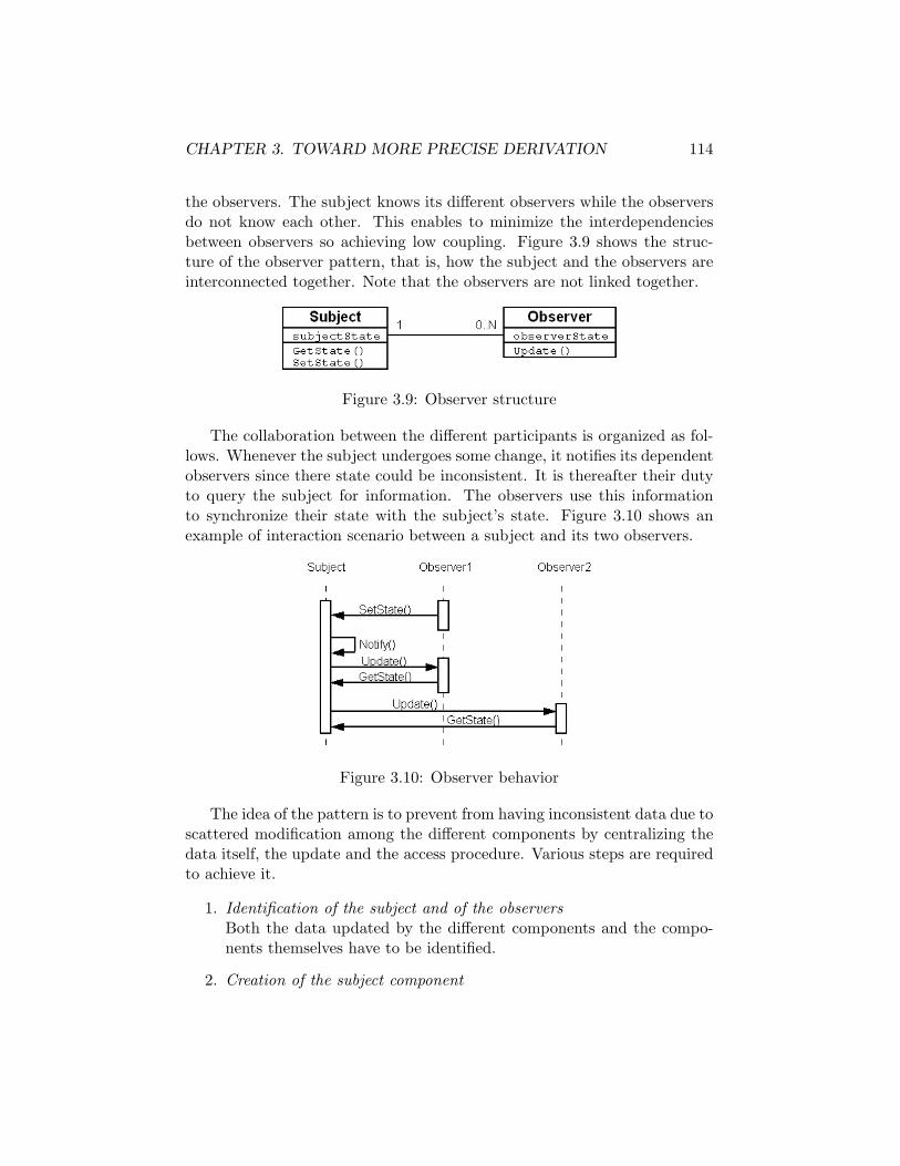
CHAPTER 3. TOWARD MORE PRECISE DERIVATION 114
the observers. The subject knows its different observers while the observersdo not know each other. This enables to minimize the interdependenciesbetween observers so achieving low coupling. Figure 3.9 shows the struc-ture of the observer pattern, that is, how the subject and the observers areinterconnected together. Note that the observers are not linked together.
Figure 3.9: Observer structure
The collaboration between the different participants is organized as fol-lows. Whenever the subject undergoes some change, it notifies its dependentobservers since there state could be inconsistent. It is thereafter their dutyto query the subject for information. The observers use this informationto synchronize their state with the subject’s state. Figure 3.10 shows anexample of interaction scenario between a subject and its two observers.
Figure 3.10: Observer behavior
The idea of the pattern is to prevent from having inconsistent data due toscattered modification among the different components by centralizing thedata itself, the update and the access procedure. Various steps are requiredto achieve it.
1. Identification of the subject and of the observersBoth the data updated by the different components and the compo-nents themselves have to be identified.
2. Creation of the subject component

CHAPTER 3. TOWARD MORE PRECISE DERIVATION 115
Figure 3.11: Identification of the subject and the observers
Once the subject has been identified, the subject component can becreated. More accurately, a generic subject component is instantiatedto suit the particular needs of the data. The subject component shoulddefine in its interface a procedure to enable observers to update andto obtain its state.
3. Adaptation of the observers behaviorEach time an observer modifies the data, it has to update the subjectstate and each time it receives a notification from the subject it hasto get the new state from the object
4. Suppression of the old synchronization mechanismsThe old interactions between the different observers in order to syn-chronize their data have to be deleted since this is now done throughthe subject.
5. Addition of new connectors between the subject and the observersIn order to enable the subject and the observers to communicate, newconnectors have to be added.
The identification of the subject and observers is done without any realdifficulty from the initial fragment. As shown in Figure 3.8 the two observersare C1 and C2. The subject is the common data updated by both C1 and C2.It is indicated on the graphical representation by two dataflow connectors,each one carrying different attributes of the same object. This is illustratedin Figure 3.11.
The subject component should have three operations: one to allow ob-server to update its state, one to allow observer to get its state and one tonotify all its observers when some modifications has occured. The Update

CHAPTER 3. TOWARD MORE PRECISE DERIVATION 116
operations should therefore be directly followed by the notify operation. Thecomponent subject can be defined in Wright as follows:
component Subject
port Observer1,2Link ={
SetState?x → Notify → Observer1,2Link[] GetState?x → SendState!y → Observer1,2Link
computation = SetState → Notify [] GetState whereSetState=(Observer1.SetState?x [] Observer2.SetState?x)Notify = (Observer1.Notify ‖Observer2.Notify)→ computation
GetState =
(Observer1.GetState?x → Observer1.SendState!y→ computation)[](Observer2.GetState?x → Observer2.SendState!y→ computation
Thereafter the observers behavior has to be modified so as to ensuretwo things. First every update on the observer state is effectively reflectedon subject state. Secondly every notification of a change received from thesubject leads to a query to the subject in order to synchronize observer stateand subject state. In order to support these new characteristics, the Wrightcomponent of the observer can be modified as follows:
component Observer
port ToOtherObserver . . .
computation = compute [] §wherecompute = . . .→ Modify(x) → . . .
component NewObserver
port ToOtherObserver . . .
port SubjectLink ={
SetState!x → SubjectLink[] Notify → GetState!x → SendState?y → SubjectLink
computation = compute [] Update wherecompute = . . .→ Modify(x) → SubjectLink.SetState!x . . .
Update =
Subject.Notify → SubjectLink.GetState!x→ SubjectLink.SendState?y → SynchronizeV alue→ computation
All the communications between the observers aiming at keeping thestate of the subject consistent and coherent must be deleted. This may re-sult in the suppression of a connector and therefore of a port in the Wright
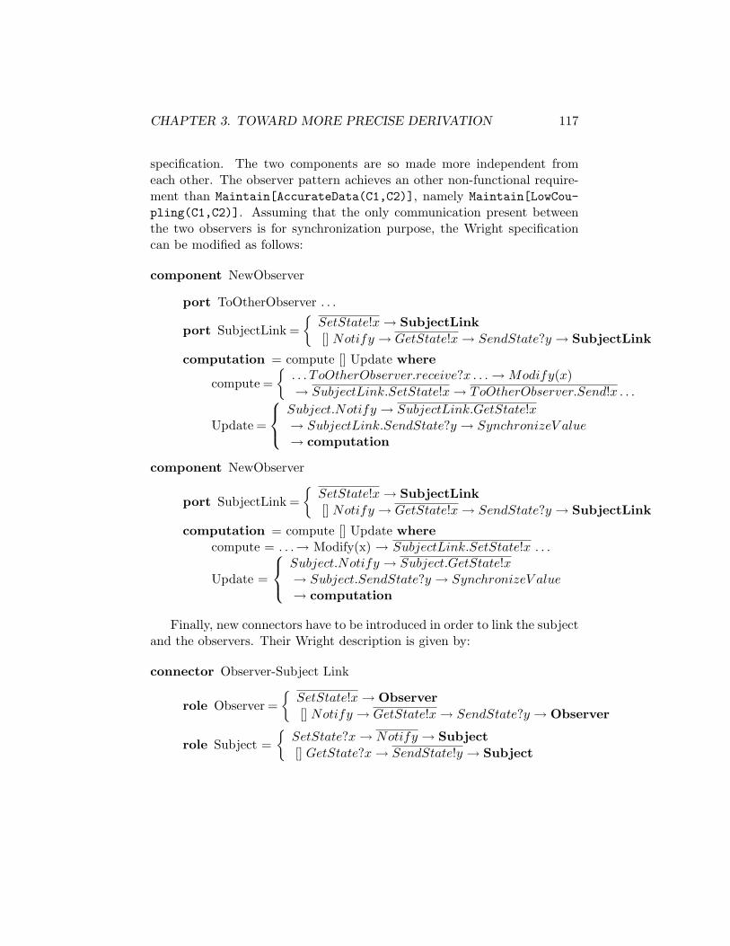
CHAPTER 3. TOWARD MORE PRECISE DERIVATION 117
specification. The two components are so made more independent fromeach other. The observer pattern achieves an other non-functional require-ment than Maintain[AccurateData(C1,C2)], namely Maintain[LowCou-pling(C1,C2)]. Assuming that the only communication present betweenthe two observers is for synchronization purpose, the Wright specificationcan be modified as follows:
component NewObserver
port ToOtherObserver . . .
port SubjectLink ={
SetState!x → SubjectLink[] Notify → GetState!x → SendState?y → SubjectLink
computation = compute [] Update where
compute ={
. . . T oOtherObserver.receive?x . . . → Modify(x)→ SubjectLink.SetState!x → ToOtherObserver.Send!x . . .
Update =
Subject.Notify → SubjectLink.GetState!x→ SubjectLink.SendState?y → SynchronizeV alue→ computation
component NewObserver
port SubjectLink ={
SetState!x → SubjectLink[] Notify → GetState!x → SendState?y → SubjectLink
computation = compute [] Update wherecompute = . . .→ Modify(x) → SubjectLink.SetState!x . . .
Update =
Subject.Notify → Subject.GetState!x→ Subject.SendState?y → SynchronizeV alue→ computation
Finally, new connectors have to be introduced in order to link the subjectand the observers. Their Wright description is given by:
connector Observer-Subject Link
role Observer ={
SetState!x → Observer[] Notify → GetState!x → SendState?y → Observer
role Subject ={
SetState?x → Notify → Subject[] GetState?x → SendState!y → Subject

CHAPTER 3. TOWARD MORE PRECISE DERIVATION 118
Figure 3.12: Observer pattern transformation rule
glue =
Observer.SetState!x→ Subject.SetState?x → Notify where[]Notify
Notify =
Subject.Notify → Observer.Notify
→ Observer.GetState!x → Subject.GetState?x→ Subject.SendState!y → Observer.SendState?y → glue
The observer pattern as described here is a bit different from what wassuggested in Figure 3.8 since the connector between C1 and C2 is deleted(only if its only purpose is to transmit the object x). This enables to achievelow coupling between C1 and C2 in addition to the initial non-functional re-quirement (Maintain[AccurateData(C1,C2)]). The graphical representa-tion of the transformation rule is therefore slightly different and is presentedin Figure 3.12.
Application of the pattern on Acquisition Unit and IMS
The pattern was applied on Acquisition Unit and IMS without any partic-ular difficulty. The specification of the initial architecture fragment together

CHAPTER 3. TOWARD MORE PRECISE DERIVATION 119
with the architecture specification resulting from the application of the ob-server pattern can be found in Appendix C.2.
3.5 Discussion
In this chapter, the use of Wright has been examined in order to derive amore precise architecture. The two goals pursued were the addition of abehavioral view to the architecture resulting from the KAOS method andto describe the architecture parts resulting from the application of patterns.
The first objective was reached through the introduction of translationmechanisms from KAOS architecture descriptions to Wright specifications.Those mechanisms deal with both the structural and the behavioral aspects.Rules expressed the former while heuristics the latter. This difference ofpower is caused by two facts:
1. The constructs used by KAOS and Wright dealing with the structureare essentially the same.
2. The behavioral view is only partially present in the KAOS architec-ture description and the global control flow has to be inferred fromoperations specification.
Moreover Wright does not support temporal logic and there is inevitablya loss of semantic during the translation. Nevertheless Wright specificationsof architecture provide a significantly more precise architecture description.From the addition of behavior specifications, might follow the possibility tovalidate the architecture with respect to the functional requirements. Theanimator ProBE[14] available for CSP could be used to visualize the possibleexecution traces so enabling to check whether the architecture meets thefunctional requirements.
Two patterns have been examined using Wright: the fault-tolerant com-munication pattern and the observer pattern. Both the resulting architec-ture fragment and the transformation process have been described. It is nowclear how the application of these patterns modifies the involved componentsand connectors specification as well as the exact functionalities performedby the added ones.
These two areas of improvement have been validated on the power plantsupervisory system. In both cases the results are very encouraging. Thedefined rules and heuristics provide a significant help to derive the Wrightspecifications from the KAOS architecture description and the application

CHAPTER 3. TOWARD MORE PRECISE DERIVATION 120
of the two patterns does not present any difficulty. The introduced approachseems very productive.
Conclusion
This thesis evaluated and compared two methods for deriving architecturefrom goal-oriented requirements. The KAOS method and the Preskriptorprocess were validated via their application on a power plant supervisorysystem. The system was developed by ENEL, this Italian electricity com-pany and its description was extracted from papers reporting the project.
The conducted analysis shows as main result that both approaches seemeffective. The two resulting architectures satisfy all the functional and mostof the non-functional requirements. Performance was for example left un-handled in both cases. Some weaknesses were nonetheless present. Nei-ther method produced an architecture description dealing with behavioralaspects. The descriptions were essentially structural while the way the dif-ferent components interact with each other remained uncovered. Moreoverthe derivation processes in themselves appear to be a bit hazy in certainaspects. Pattern and styles description with respect to their choice, theirapplicability and the architecture resulting from their application is up tonow only suggested by the KAOS method. The treatment of non-functionalrequirements in the Preskriptor process is so far only done for particularexamples and does not provide sufficient guidance to be really useful.
The two methods differ greatly by their intent and this is reflected by theresulting architectures. On the one hand the KAOS method aims at makingthe derivation process as automated and clear as possible so as to providethe maximum level of guidance to the architect. It also targets an archi-tectural description as precise and complete as possible in order to bringthe maximum support to designers. On the other hand the Preskriptor pro-cess lets more freedom to the architect and uses the concept of architecturalprescriptions – expressed in the domain language by opposition to classicaldescriptions expressed in solution language – so as to make the transitionfrom requirements as smooth as possible. The resulting architecture is there-fore less constraining and complete, so letting free the designer to choose thelow level design.
121
CONCLUSION 122
In order to improve the KAOS method the use of an architecture descrip-tion language was explored. Wright was chosen for its ability to describethe multiple facets of an architecture and more particularly the behavioralaspect. Moreover it provides formal reasoning capabilities enabling for ex-ample to check for absence of deadlock. It has been argued for an integraterather than a sequential approach where the Wright specification is derivedincrementally from the intermediate results produced by the KAOS method.Various mechanisms have therefore been introduced to derive a Wright spec-ification from the abstract data flow architecture. These include a set ofrules and heuristics enabling to derive the component behavior from KAOSoperations specifications. The one ruling the application order of opera-tions seems particularly useful. The ability of Wright to describe patternsthereafter has been examined. Two pattern examples were inspected in de-tails: the fault-tolerant communication pattern and the observer pattern.Each of them has been described extensively in terms of the architecturaltransformation involved as well as regarding the resulting architecture. Itemerges from their application to the power plant supervisory system thatthe introduced approach is highly productive.
The work presented in this thesis contributes to both methods studiedby confronting them to a real safety-critical system whose size is reasonable.Moreover significant improvements have been made to the KAOS methodby integrating the benefits of architectural descriptions languages.
Nonetheless a lot of questions remain open, leaving space for furtherwork.
Although styles description was identified as a weakness of the KAOSmethod, no improvement has been proposed in this direction. Few styles areavailable and both their choice and application are so far very qualitative.They should therefore be investigated further.
Proposed improvements on patterns do not address all the problems.When two patterns are applicable, the issue of combining them, providedthey can be combined, is still unclear. Do they keep their efficiency towardnon-functional requirements satisfaction while they are combined? If not,how to choose the one to apply? Does the order of application matter? Onceone pattern has been applied, will the resulting piece of architecture stillmatch the applicability condition of the other? In addition, the descriptionof the applicability condition is up to now very informal. All those concernsneed to be studied.
Wright is currently underused since none of its formal reasoning capa-bilities have been explored so far. Patterns are not supposed to preventsatisfaction of any functional goal they should therefore not modify the

CONCLUSION 123
global behavior of the fragment affected by their application. Some furtherwork should include a validation of the introduced patterns with respect tothat condition.
More globally, the validation of the architecture with respect to func-tional requirements should be examined. To this end, the use of the existinganimator for CSP (ProBE) should be inspected. The visualization of thepossible execution traces could be a mean to check whether the architecturemeets the functional requirements.
Finally, the architecture derivation process is so far not supported by anytool. A potential tool should integrate closely with the derivation process,that is, each step should be supported separately. The support provided ateach step should include a derivation part as well as a validation part. Thederivation part should help the architect both in his choices (e.g., choiceof the suitable style/pattern, application of the correct heuristic) and intheir application. The validation part should include an animator so as toprovide the architect with a graphical mean to explore the system behaviorand a model checker to verify the satisfaction of system properties such asdeadlock freedom.

Bibliography
[1] Allen, R. A Formal Approach to Software Architecture. PhD thesis,Carnegie Mellon University, May 1997.
[2] Allen, R., and Garlan, D. A formal basis for architectural connec-tion. ACM Transactions on Software Engineering and Methodology 6,3 (July 1997), 213–249.
[3] Arora, A., and Kulkarni, S. S. Designing masking fault-tolerancevia nonmasking fault-tolerance. IEEE Transactions On Sofware Engi-neering 24, 6 (June 1998), 435–450.
[4] Brandozzi, M. From goal oriented requirements specifications to ar-chitectural prescriptions. Master’s thesis, The University of Texas atAustin, 2001.
[5] Brandozzi, M., and Perry, D. E. Transforming goal oriented re-quirement specifications into architectural prescriptions. In Proceedingsof STRAW 2001 - From Software Requirements to Architectures (2001),Castro and Kramer, Eds., pp. 54–60.
[6] Brandozzi, M., and Perry, D. E. Architectural prescriptions fordependable systems. In Proceedings of ICSE 2002 - International Work-shop on Architecting Dependable Systems (Orlando, May 2002).
[7] Chandra, T. D., and Toueg, S. Unreliable failure detectors forreliable distributed systems. Journal of the ACM 43, 2 (March 1996),225–267.
[8] Ciapessoni, E., Mirandola, P., Coen-Porisini, A., Mandrioli,D., and Morzenti, A. From formal models to formally based meth-ods: an industrial experience. ACM Transactions on Software Engi-neering and Methodology 8, 1 (January 1999), 79–113.
124

BIBLIOGRAPHY 125
[9] Coen-Porisini, A., and Mandrioli, D. Using trio for designing acorba-based application. Concurrency: Practical and Experience 12, 10(August 2000), 981–1015.
[10] Coen-Porisini, A., Pradella, M., Rossi, M., and Mandrioli, D.A formal approach for designing corba based applications. In Proceed-ings of the 22nd International Conference on on Software Engineering- ICSE’2000 (Limerick, June 2000), ACM Press, pp. 188–197.
[11] Darimont, R. Process Support for Requirement Elaboration. PhDthesis, Universite catholique de Louvain, 1995.
[12] Darimont, R., and van Lamsweerde, A. Formal refinement pat-terns for goal-driven requirements elaboration. In Proceedings of the 4thACM Symposium on the Foundations of Software Engineering - FSE’96(San Fransisco, October 1996), ACM Press, pp. 179–190.
[13] Formal Systems (Europe) Ltd. Failures-Divergence Refinement:FDR2 User Manual. Oxford, England, May 2003. http://www.fsel.com.
[14] Formal Systems (Europe) Ltd. Process Behavior Explorer: ProBEUser Manual. Oxford, England, January 2003. http://www.fsel.com.
[15] Gamma, E., Helm, R., Johnson, R., and Vlissides, J. Design pat-terns - Elements of reusable object-oriented software. Addison-Wesley,1995, pp. 293–299.
[16] Garlan, D. Formal modeling and analysis of software architecture:Components, connectors, and events. In Formal Methods for SoftwareArchitectures, M. Bernardo and P. Inverardi, Eds., vol. 2804 of LectureNotes in Computer Science. Springer-Verlag, 2003, pp. 1–24.
[17] Gartner, F. C. Fundamentals of fault-tolerant distributed computingin asynchronous environments. ACM Computing Surveys 31, 1 (March1999), 1–26.
[18] Kramer, J., Magee, J., and Uchitel, S. Software architecturemodeling & analysis: A rigorous approach. In Formal Methods forSoftware Architectures, M. Bernardo and P. Inverardi, Eds., vol. 2804of Lecture Notes in Computer Science. Springer-Verlag, 2003, pp. 44–51.

BIBLIOGRAPHY 126
[19] Letier, E., and van Lamsweerde, A. Agent-based tactics for goal-oriented requirements elaboration. In Proceedings of the 24th Interna-tional Conference of Software Engineering - ICSE’2002 (Orlando, May2002), ACM Press, pp. 83–93.
[20] Letier, E., and van Lamsweerde, A. Deriving operational soft-ware specifications from system goals. In Proceedings of the 10th ACMSymposium on the Foundations of Software Engineering - FSE’2002(Charleston, November 2002), ACM Press, pp. 119–128.
[21] Magee, J., Dulay, N., Eisenbach, S., and Kramer, J. Specify-ing distributed software architectures. In Proceedings of the 5th Euro-pean Software Engineering Conference - ESEC’95 (September 1995),Springer-Verlag, pp. 137–153.
[22] Manna, Z., and Pnueli, A. The Temporal Logic of Reactive andConcurrent Systems: Specification. Springer-Verlag, 1992, ch. 3.
[23] Medvidovic, N., Oreizy, P., Robbins, J. E., and Taylor, R. N.Using object-oriented typing to support architectural design in the c2style. In Proceedings of the 4th ACM SIGSOFT symposium on Founda-tions of software engineering - FSE’96 (1996), ACM Press, pp. 24–32.
[24] Perry, D. E., and Wolf, A. L. Foundations for the study of soft-ware architecture. ACM SIGSOFT Software Engineering Notes 17, 4(October 1992), 40–52.
[25] Ricciardi, A. M., and Birman, K. P. Using process groups toimplement failure detection in asynchronous environments. In Proceed-ings of the tenth annual ACM symposium on Principles of distributedcomputing (1991), ACM Press, pp. 341–353.
[26] Shaw, M., and Garlan, D. Software Architecture: Perspectives onan Emerging Discipline. Prentice-Hall, 1996.
[27] van Lamsweerde, A. From system goals to software architecture. InFormal Methods for Software Architectures, M. Bernardo and P. Inver-ardi, Eds., vol. 2804 of Lecture Notes in Computer Science. Springer-Verlag, 2003, pp. 25–43.
[28] van Lamsweerde, A., Darimont, R., and Letier, E. Managingconflicts in goal-driven requirements engineering. IEEE Transaction onSoftware Engineering 24, 11 (November 1998), 908–926.

BIBLIOGRAPHY 127
[29] van Lamsweerde, A., and Letier, E. Handling obstacles in goal-oriented requirements engineering. IEEE Transaction on Software En-gineering 26, 10 (October 2000), 978–1005.
List of Figures
1.1 Preliminary goal graph for the power plant supervisory system 121.2 First draft of the object model . . . . . . . . . . . . . . . . . 131.3 Second draft of the object model . . . . . . . . . . . . . . . . 131.4 Addition of missing goals via WHY elicitation . . . . . . . . . 141.5 Addition of missing subgoals via HOW elicitation . . . . . . . 151.6 Potential agents . . . . . . . . . . . . . . . . . . . . . . . . . . 151.7 Assigned agents, their interfaces and data dependencies . . . 251.8 Derived dataflow architecture . . . . . . . . . . . . . . . . . . 261.9 Event-based style transformation rule . . . . . . . . . . . . . 271.10 Style-based architecture . . . . . . . . . . . . . . . . . . . . . 271.11 The NoReadUpNoWriteDown pattern for condidentiality goals . 291.12 The 3 required steps of the Preskriptor process . . . . . . . . 311.13 Step 4 of the Preskriptor process . . . . . . . . . . . . . . . . 33
2.1 The ENEL’s supervision and control system[8] . . . . . . . . 362.2 Milestone refinement pattern . . . . . . . . . . . . . . . . . . 392.3 General Structure of the goal diagram . . . . . . . . . . . . . 402.4 Refinement of the goal FaultsDetected . . . . . . . . . . . . 402.5 Refinement of the goal AlarmCorrectlyManaged . . . . . . . 412.6 Communication reliability refinement subtree . . . . . . . . . 422.7 Transmission meta-relationship . . . . . . . . . . . . . . . . . 432.8 Bounded achieve opeartionalization pattern . . . . . . . . . . 472.9 Immediate achieve operationalization pattern . . . . . . . . . 482.10 Refinement and obstacles for the goal FaultDetectedWhen-
CalculationDone . . . . . . . . . . . . . . . . . . . . . . . . 522.11 Abstract dataflow architecture . . . . . . . . . . . . . . . . . 572.12 Centralized communication architectural style . . . . . . . . . 582.13 Style-based refined architecture . . . . . . . . . . . . . . . . . 592.14 Fault-tolerant refinement pattern . . . . . . . . . . . . . . . . 60
128

LIST OF FIGURES 129
2.15 Consistency maintainer refinement pattern . . . . . . . . . . . 612.16 Pattern-based refined architecture . . . . . . . . . . . . . . . 622.17 component refinement tree resulting from step 1 . . . . . . . 632.18 Component refinement tree resulting from step 3 . . . . . . . 672.19 Box-and-line diagram . . . . . . . . . . . . . . . . . . . . . . 68
3.1 Fragment of an abstract dataflow architecture . . . . . . . . . 843.2 Example of interaction scenario for the ”push” behavior . . . 853.3 Example of interaction scenario for the ”pull” behavior . . . . 853.4 Milestone refinement pattern with corresponding operational-
izations . . . . . . . . . . . . . . . . . . . . . . . . . . . . . . 933.5 Fragment of the dataflow architecture containing PRECON and
ALARM . . . . . . . . . . . . . . . . . . . . . . . . . . . . . . . 963.6 Fault-tolerant communication pattern . . . . . . . . . . . . . 1063.7 Fault-tolerant communication pattern Transformation rule . . 1123.8 Observer pattern . . . . . . . . . . . . . . . . . . . . . . . . . 1133.9 Observer structure . . . . . . . . . . . . . . . . . . . . . . . . 1143.10 Observer behavior . . . . . . . . . . . . . . . . . . . . . . . . 1143.11 Identification of the subject and the observers . . . . . . . . 1153.12 Observer pattern transformation rule . . . . . . . . . . . . . . 118
A.1 Functional goal diagram . . . . . . . . . . . . . . . . . . . . . 132A.2 Non-functional goal diagram . . . . . . . . . . . . . . . . . . . 143A.3 ObjectDiagram . . . . . . . . . . . . . . . . . . . . . . . . . . 144A.4 Responsibility assignment of the different agents . . . . . . . 150A.5 Agent context diagram . . . . . . . . . . . . . . . . . . . . . . 151A.6 Modifications brought to the NFG diagram after the obstacle
analysis . . . . . . . . . . . . . . . . . . . . . . . . . . . . . . 163

List of Tables
1.1 Comparison between C2, Darwin and Wright . . . . . . . . . 231.2 Mapping KAOS entities to APL entities[4] . . . . . . . . . . . 31
2.1 Comparison between the resulting architectures . . . . . . . . 70
3.1 Cases where Op1 and Op2 must be applied sequentially . . . 913.2 Four Forms of Fault Tolerance . . . . . . . . . . . . . . . . . 104
130

Appendix A
KAOS Specifications
A.1 Goal specifications
A.1.1 Functional goals
The functional goals are listed following an alphabetical order. Figure A.1shows the functional goal diagram.
1. Goal AlarmCorrectlyManaged
Def The system must raised an alarm each time a fault is de-tected. In addition, it must trace and keep the state of allthe alarms previously raised.
Concerns Alarm, FaultAndRefines PerformanceOfThePlantMonitoredRefinedTo AlarmRaisedIffFaultDetected, AlarmTraced, Oper-
atorInterractionManaged
2. Goal AlarmDiagnosisWritten
Def Each time an alarm is raised, information on that alarmmust be kept in the DataBase.
Concerns Alarm, AlarmInformation, FaultInformationAndRefines AlarmInformationStoredWhenAlarmRaisedRefinedTo AlarmDataTransmittedToDB,
DataCorrectlyUpdatedFormalDef ∀ a: Alarm, ∃ !fi:FaultInformation, ∃ !ai: AlarmIn-
formation, ∃ !ad: AlarmDiagnosisRaise(fi,a) ⇒ ♦ Stored(ai,DB)∧ Representation(ai,a)∧ Concerns(ad,fi,ai) ∧ Stored(ad,DB)
131

APPENDIX A. KAOS SPECIFICATIONS 132
Figure A.1: Functional goal diagram

APPENDIX A. KAOS SPECIFICATIONS 133
3. Goal AlarmInformationProvidedUponUserRequest
Def Operators should be able to retrieve informations about allthe alarms previously raised
Concerns Alarm, AlarmInformationAndRefines AlarmTracedRefinedTo CorrectDataPersistentlyStored, QuerryTransmitted,
QuerryAnsweredFormalDef ∀ a:Alarm, ∃ !ai:AlarmInformation
Querry(a) ⇒ ♦ Answer(ai) ∧ Representation(ai,a)
4. Goal AlarmInformationStoredWhenAlarmRaised
Def Each time an alarm is raised, information on that alarmmust be kept in the DataBase.
Concerns Alarm, AlarmInformation, PowerPlant/AlarmStatusAndRefines AlarmTracedRefinedTo AlarmDiagnosisWritten, AlarmStatusUpdatedFormalDef ∀ a:Alarm, ∃ ! fi: FaultInformation, ∃ !ai: AlarmIn-
formation, ∃ !fd: FaultDiagnosisRaise(fi,a) ∧ Representation(ai,a) ⇒ ♦ Stored(ai,DB)∧ Stored(fd,DB) ∧ Concerns(fd,fi,ai)∧ PowerPlant.AlarmStatus =’on’
5. Goal AlarmNotRaisedIfFaultNotDetected
Def If no fault is detected no alarm can be raisedConcerns Alarm, FaultAndRefines AlarmRaisedIffFaultDetectedUnderResponsabilityOf ALARMFormalDef ∀ a:Alarm, ∃ !f:Fault,∃ !l:Location
Raise(f,a) ⇒ � Detected(f,l)
6. Goal AlarmRaisedIffFaultDetected
Def The alarm has to be raised if and only if a fault has beendetected
Concerns AlarmAndRefines AlarmCorrectlyManagedRefinedTo FaultInformationTransmittedWhenFaultDetected,
AlarmRaisedWhenFaultInformationTransmitted,AlarmNotRaisedIfFaultNotDetected

APPENDIX A. KAOS SPECIFICATIONS 134
FormalDef ∀ f:Fault, ∃ !l:Location,∃ !a:AlarmDetected(f,l) ⇒ ♦ Raise(f,a)∧∀ a:Alarm, ∃ !f:Fault,∃ !l:Location
Raise(f,a) ⇒ � Detected(f,l)
7. Goal AlarmRaisedWhenFaultInformationTransmitted
Def Each time the ALARM unit receive information on a fault,an alarm has to be raised
Concerns Alarm, FaultInformationAndRefines AlarmRaisedIffFaultDetectedUnderResponsabilityOf ALARMFormalDef ∀ fi:FaultInformation, ∃ !a:Alarm
Transmitted(fi, PRECON, ALARM) ⇒ ♦ Raise(fi,a)
8. Goal AlarmStatusUpdated
Def If there is at least one alarm raised, the AlarmStatus mustbe set to on, otherwise it must be set to off.
Concerns Alarm, Fault, PowerPlant/AlarmStatusAndRefines AlarmInformationStoredWhenAlarmRaisedUnderResponsabilityOf ALARMFormalDef ∀ a: Alarm, ∃ !fi:FaultInformation
Raise(fi,a) ⇒ ◦ PowerPlant.AlarmStatus=’on’
9. Goal AlarmTraced
Def Informations on alarms previously raised can be retrievedConcerns AlarmAndRefines AlarmCorrectlyManagedRefinedTo AlarmInformationStoredWhenAlarmRaised,
AlarmInformationProvidedUponUserRequest
10. Goal AnalogDataAcquired
Def All the data coming from working analog sensors are ac-quired
Concerns Sensor, SensorInformationAndRefines DataAcquiredFromTheFieldFormalDef ∀ s: Sensor, si:SensorInformation
s.type =’Analog’ ∧ s.status =’on’ ∧ s.id = si.id ⇒ ♦ Ac-quired(s) ∧ s.DataValue=si.DataValue

APPENDIX A. KAOS SPECIFICATIONS 135
11. Goal CalculationDone
Def All the calculations needed to detect fault in the Power-Plant are done
Concerns SensorInformationAndRefines ChecksPerformedWhenDataAcquiredUnderResponsabilityOf PRECONFormalDef ∀ si:SensorInformation
Transmitted(si,DB,PRECON) ⇒ ♦ CalculationDone
12. Goal ChecksPerformedWhenDataAcquired
Def Checks must be performed when all the data needed isavailable in order to detect faults in the Steam Condenseror in the Cooling Circuit
Concerns SensorInformation, FaultAndRefines PeriodicalChecksPerformedRefinedTo CalculationDone, FaultDetectedWhenCalculation-
DoneFormalDef ∀ f:Fault, si: SensorInformation, l:Location
Occurs(f,l) ∧ Transmitted(si,DB,PRECON)⇒ ♦≤5min Detected(f,l)∧¬ Occurs(f,l) ∧ Transmitted(si,DB,PRECON)
⇒ ♦ ¬ Detected(f,l)
13. Goal ComputedVariablesStored
Def The variables resulting from the different calculations needin order to detect Fault must be stored.
AndRefines ReportWrittenWhenCheckPerformedRefinedTo DataTransmittedToDB
14. Goal ConsistencyCheckPerformed
Def Consistency checks are performed on all the acquired datain order to ensure consistency within all the sensor datas
Concerns SensorInformationAndRefines CorrectDataPersistentlyStoredUnderResponsabilityOf ACQUISITION UNITFormalDef ∀ s: Sensor
Acquired(s) ⇒ ♦ Consistent(s)
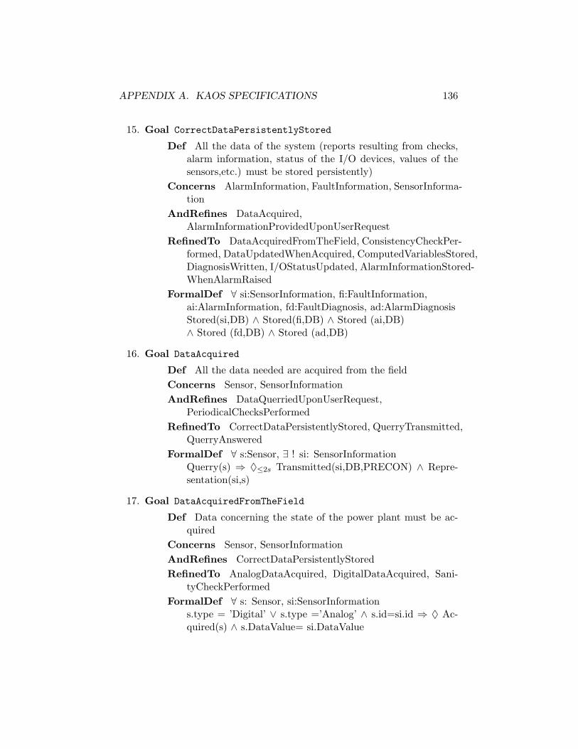
APPENDIX A. KAOS SPECIFICATIONS 136
15. Goal CorrectDataPersistentlyStored
Def All the data of the system (reports resulting from checks,alarm information, status of the I/O devices, values of thesensors,etc.) must be stored persistently)
Concerns AlarmInformation, FaultInformation, SensorInforma-tion
AndRefines DataAcquired,AlarmInformationProvidedUponUserRequest
RefinedTo DataAcquiredFromTheField, ConsistencyCheckPer-formed, DataUpdatedWhenAcquired, ComputedVariablesStored,DiagnosisWritten, I/OStatusUpdated, AlarmInformationStored-WhenAlarmRaised
FormalDef ∀ si:SensorInformation, fi:FaultInformation,ai:AlarmInformation, fd:FaultDiagnosis, ad:AlarmDiagnosisStored(si,DB) ∧ Stored(fi,DB) ∧ Stored (ai,DB)∧ Stored (fd,DB) ∧ Stored (ad,DB)
16. Goal DataAcquired
Def All the data needed are acquired from the fieldConcerns Sensor, SensorInformationAndRefines DataQuerriedUponUserRequest,
PeriodicalChecksPerformedRefinedTo CorrectDataPersistentlyStored, QuerryTransmitted,
QuerryAnsweredFormalDef ∀ s:Sensor, ∃ ! si: SensorInformation
Querry(s) ⇒ ♦≤2s Transmitted(si,DB,PRECON) ∧ Repre-sentation(si,s)
17. Goal DataAcquiredFromTheField
Def Data concerning the state of the power plant must be ac-quired
Concerns Sensor, SensorInformationAndRefines CorrectDataPersistentlyStoredRefinedTo AnalogDataAcquired, DigitalDataAcquired, Sani-
tyCheckPerformedFormalDef ∀ s: Sensor, si:SensorInformation
s.type = ’Digital’ ∨ s.type =’Analog’ ∧ s.id=si.id ⇒ ♦ Ac-quired(s) ∧ s.DataValue= si.DataValue

APPENDIX A. KAOS SPECIFICATIONS 137
18. Goal DataCorrectlyUpdated
Def Each time alarm information is transmitted to the Data-Base, this information has to be stored
Concerns AlarmInformation, DataBaseAndRefines AlarmInformationStoredWhenAlarmRaisedUnderResponsabilityOf DBFormalDef ∀ ai:AlarmInformation, ad:AlarmDiagnosis
Transmitted(ai,ALARM,DB) ⇒ ♦ Stored(ai,DB)Transmitted(ad,ALARM,DB) ⇒ ♦ Stored(ad,DB)
19. Goal DataCorrectlyUpdated
Def Each time fault information is transmitted to the DataBase,this information has to be stored
Concerns FaultInformation, DataBaseAndRefines FaultDiagnosisWritten, ComputedVariablesStoredUnderResponsabilityOf DBFormalDef ∀ fi:FaultInformation, fd:FaultDiagnosis
Transmitted(fi,ALARM,DB) ⇒ ♦ Stored(fi,DB)Transmitted(fd,ALARM,DB) ⇒ ♦ Stored(fd,DB)
20. Goal DataQuerriedUponUserRequest
Def All the data concerning the state of the Power Plant mustbe provided upon operators request
ConcernsAndRefines FaultDetectedInSteamCondensor, FaultDetected-
InCoolingCircuitRefinedTo CorrectDataPersistentlyStored,
QuerryTransmitted, QuerryAnsweredFormalDef ∀ s: Sensor, ∃ ! si: SensorInformation
Querry(s) ⇒ ♦ Answer(si) ∧ Representation(si,s)
21. Goal DataTransmittedToDB
Def Each time an alarm is raised, corresponding informationmust be transmitted to the DataBase
Concerns Alarm, AlarmInformation, FaultInformationAndRefines AlarmInformationStoredWhenAlarmRaisedUnderResponsabilityOf COMMUNICATION

APPENDIX A. KAOS SPECIFICATIONS 138
FormalDef ∀ a:Alarm, ∃ ! fi: FaultInformation,∃ ! ai:AlarmInformation, ∃ !ad: AlarmDiagnosisRaise(fi,a) ∧ Representation(ai,a)⇒ ♦ Transmitted(ai,ALARM,DB) ∧ Transmitted(ad,ALARM,DB)∧ Concerns(ad,fi,ai)
22. Goal DataTransmittedToDB
Def Each time an fault is detected, corresponding informationmust be transmitted to the DataBase
Concerns Fault , FaultInformation, SensorInformationAndRefines FaultDiagnosisWritten, ComputedVariablesStoredUnderResponsabilityOf COMMUNICATIONFormalDef ∀ f:Fault, ∃ l:Location, ∃ ! fi: FaultInformation,
∃ ! si: SensorInformation ∃ !ad: FaultDiagnosisDetected(f,l) ∧ Representation(fi,f)⇒ ♦ Transmitted(fi,PRECON,DB) ∧ Transmitted(fd,ALARM,DB)∧ Concerns(ad,si,fi)
23. Goal DataUpdatedWhenAcquired
Def When the data have been acquired, they must be storedcorrectly
Concerns Sensor, SensorInformationAndRefines CorrectDataPersistentlyStoredUnderResponsabilityOf DBFormalDef ∀ si:Sensor
Acquired(s) ∧ Consistent(s) ⇒ ♦ Stored(si,DB)∧ Representation(si,s)
24. Goal DigitalDataAcquired
Def All the data coming from working digital sensors are ac-quired
Concerns Sensor, SensorInformationAndRefines DataAcquiredFromTheFieldUnderResponsabilityOf Acquisition UnitFormalDef ∀ s: Sensor, si:SensorInformation
s.type =’Digital’ ∧ s.status =’on’ ∧ s.id=si.id⇒ ♦ Acquired(s)∧ s.DataValue=si.DataValue
25. Goal FaultDetected

APPENDIX A. KAOS SPECIFICATIONS 139
Def Faults occurring in any location (i.e.,the steam condenseror the cooling) circuit must be detected. Fault occur in onlyone location at a time.
Concerns SteamCondensor, CoolingCircuit, FaultAndRefines PerformanceOfThePlantMonitoredRefinedTo FaultDetectedInSteamCondensor,
FaultDetectedInCoolingCircuitFormalDef ∀ f:Fault, ∃ !l:Location
Occurs(f,l) ⇒ ♦ Detected(f,l)
26. Goal FaultDetectedInCoolingCircuit
Def Faults in the cooling circuit must be detectedConcerns CoolingCircuit, FaultAndRefines FaultDetectedRefinedTo DataQuerriedUpondUserRequest,
PeriodicalChecksPerformed&RepportsWrittenFormalDef ∀ f:Fault
Occurs(f,CoolingCircuit) ⇒ ♦ Detected(f,CoolingCircuit)
27. Goal FaultDetectedInSteamCondenser
Def Faults in the steam condenser must be detectedConcerns SteamCondenser, FaultAndRefines FaultDetectedRefinedTo DataQuerriedUpondUserRequest,
PeriodicalChecksPerformed&RepportsWrittenFormalDef ∀ f:Fault
Occurs(f,SteamCondenser)⇒ ♦ Detected(f,SteamCondenser)
28. Goal FaultDetectedWhenCalculationDone
Def When the calculations are done, all the faults present ei-ther in the cooling circuit or in the steam condenser must bedetected
Concerns Fault, SteamCondenser, CoolingCircuitAndRefines ChecksPerformedWhenDataAcquiredUnderResponsabilityOf PRECONFormalDef ∀ f:Fault,l:Location
CalculationDone ∧ Occurs(f,l) ⇒ ♦ Detected(f,l)∧CalculationDone ∧ ¬ Occurs(f,l) ⇒ � ¬ Detected(f,l)

APPENDIX A. KAOS SPECIFICATIONS 140
29. Goal FaultDiagnosisWritten
Def Each time a fault is detected, informations concerning thefault and the diagnosis must be written
Concerns SensorInformation, FaultAndRefines ReportWrittenWhenChecksPerformedRefinedTo DataTransmittedToDB, DataCorrectlyUpdatedFormalDef ∀ f:Fault, ∃ !l: Location, ∃ !fi:FaultInformation,
∃ si:SensorInformation, ∃ !fd:FaultDiagnosisDetected(f,l) ⇒ ♦ Store(fi,DB) ∧ Representation(fi,f)∧ Stored(fd,DB) ∧ Concerns(ds, di,si)
30. Goal FaultInformationTransmittedWhenFaultDetected
Def Each time a Fault is detected, information on that faulthas to be transmitted to the ALARM unit
Concerns AlarmAndRefines AlarmRaisedIffFaultDetectedUnderResponsabilityOf COMMUNICATIONFormalDef ∀ f:Fault, ∃ !l:Location, ∃ !fi:FaultInformation
Detected(f,l) ∧ Representation(fi,f)⇒ ♦ Transmitted(fi, PRECON, ALARM)
31. Goal FaultStatusUpdated
Def If there is a least one fault detected, the FaultStatus mustbe set to on, otherwise it must be set to off
Concerns Fault, PowerPlant/FaultStatusAndRefines ReportWrittenWhenChecksPerformedUnderResponsabilityOf PRECONFormalDef ∀ f:Fault, ∃ !l :Location
Detected(f,l) ⇒ ◦ PowerPlant.FaultStatus = ’on’
32. Goal Maintain[SensorCorrectValue]
Def The values of the variables measured by the sensor shouldbe equal to the actual values of the variables.
Concerns SensorAndRefines DataAcquiredFromTheFieldUnderResponsabilityOfSensor Sensor
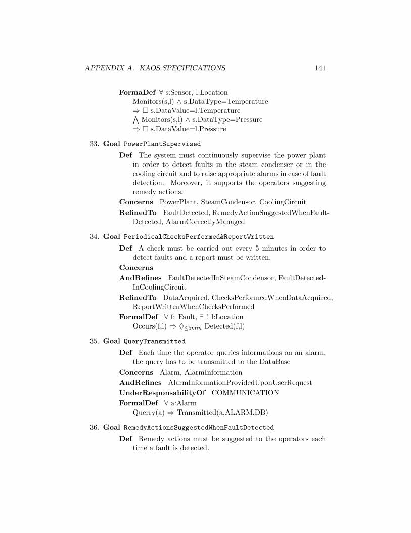
APPENDIX A. KAOS SPECIFICATIONS 141
FormaDef ∀ s:Sensor, l:LocationMonitors(s,l) ∧ s.DataType=Temperature⇒ � s.DataValue=l.Temperature∧
Monitors(s,l) ∧ s.DataType=Pressure⇒ � s.DataValue=l.Pressure
33. Goal PowerPlantSupervised
Def The system must continuously supervise the power plantin order to detect faults in the steam condenser or in thecooling circuit and to raise appropriate alarms in case of faultdetection. Moreover, it supports the operators suggestingremedy actions.
Concerns PowerPlant, SteamCondensor, CoolingCircuitRefinedTo FaultDetected, RemedyActionSuggestedWhenFault-
Detected, AlarmCorrectlyManaged
34. Goal PeriodicalChecksPerformed&ReportWritten
Def A check must be carried out every 5 minutes in order todetect faults and a report must be written.
ConcernsAndRefines FaultDetectedInSteamCondensor, FaultDetected-
InCoolingCircuitRefinedTo DataAcquired, ChecksPerformedWhenDataAcquired,
ReportWrittenWhenChecksPerformedFormalDef ∀ f: Fault, ∃ ! l:Location
Occurs(f,l) ⇒ ♦≤5min Detected(f,l)
35. Goal QueryTransmitted
Def Each time the operator queries informations on an alarm,the query has to be transmitted to the DataBase
Concerns Alarm, AlarmInformationAndRefines AlarmInformationProvidedUponUserRequestUnderResponsabilityOf COMMUNICATIONFormalDef ∀ a:Alarm
Querry(a) ⇒ Transmitted(a,ALARM,DB)
36. Goal RemedyActionsSuggestedWhenFaultDetected
Def Remedy actions must be suggested to the operators eachtime a fault is detected.

APPENDIX A. KAOS SPECIFICATIONS 142
Concerns SteamCondensor, CoolingCircuit, FaultAndRefines PerformanceOfThePlantMonitoredUnderResponsabilityOf PRECON
37. Goal ReportWrittenWhenChecksPerformed
Def Whether a fault is detected or not, all the results of thecheck must be stored.
Concerns SensorInformation, Fault, FaultInformationAndRefines PeriodicalChecksPerformedRefinedTo ComputedVariablesStored, DiagnosisWritten,
FaultStatusUpdatedFormalDef ∀ f: Fault, ∃ !fi: FaultInformation, ∃ !l:Location,
∃ ! fd: FaultDiagnosis,∃ !si:SensorInformationDetected(f,l) ⇒ ♦ Stored(fi,DB) ∧ Representation(fi,f)∧ Stored(fd,DB) ∧ Concerns(fd,si,fi)
38. Goal SanityCheckPerformed
Def Sanity checks are performed in order to ensure that allworking sensors work correctly
Concerns SensorAndRefines DataAcuiredFromTheFieldFormalDef ∀ s:Sensor
s.workingProperly = false ∧ s.status = ’on’⇒ ◦ s.status = ’off’∧
s.workingProperly = true ∧ s.status =’off’⇒ ◦ s.status = ’on’
A.1.2 Non-functional goals
Non-functional goals are listed by category. Figure A.2 shows the NFGdiagram.
• Reliability goals
Goal NoDataIntroduced
FormalDef ∀ x:Data, X:P(Data)1, A1,A2:AgentTransmitted(X,A1,A2) ∧ x ∈ Transmitted(X,A1,A2) ⇒ x ∈X
1P(Data) denotes the set of subsets of Data
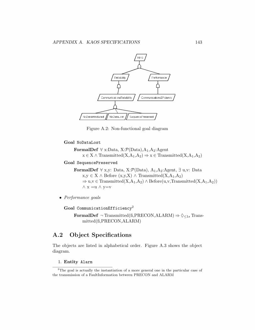
APPENDIX A. KAOS SPECIFICATIONS 143
Figure A.2: Non-functional goal diagram
Goal NoDataLost
FormalDef ∀ x:Data, X:P(Data),A1,A2:Agentx ∈ X ∧ Transmitted(X,A1,A2)⇒ x ∈ Transmitted(X,A1,A2)
Goal SequencePreserved
FormalDef ∀ x,y: Data, X:P(Data), A1,A2:Agent, ∃ u,v: Datax,y ∈ X ∧ Before (x,y,X) ∧ Transmitted(X,A1,A2)⇒ u,v ∈ Transmitted(X,A1,A2) ∧ Before(u,v,Transmitted(X,A1,A2))∧ x =u ∧ y=v
• Performance goals
Goal CommunicationEfficiency2
FormalDef ¬ Transmitted(fi,PRECON,ALARM)⇒ ♦≤1s Trans-mitted(fi,PRECON,ALARM)
A.2 Object Specifications
The objects are listed in alphabetical order. Figure A.3 shows the objectdiagram.
1. Entity Alarm
2The goal is actually the instantiation of a more general one in the particular case ofthe transmission of a FaultInformation between PRECON and ALARM
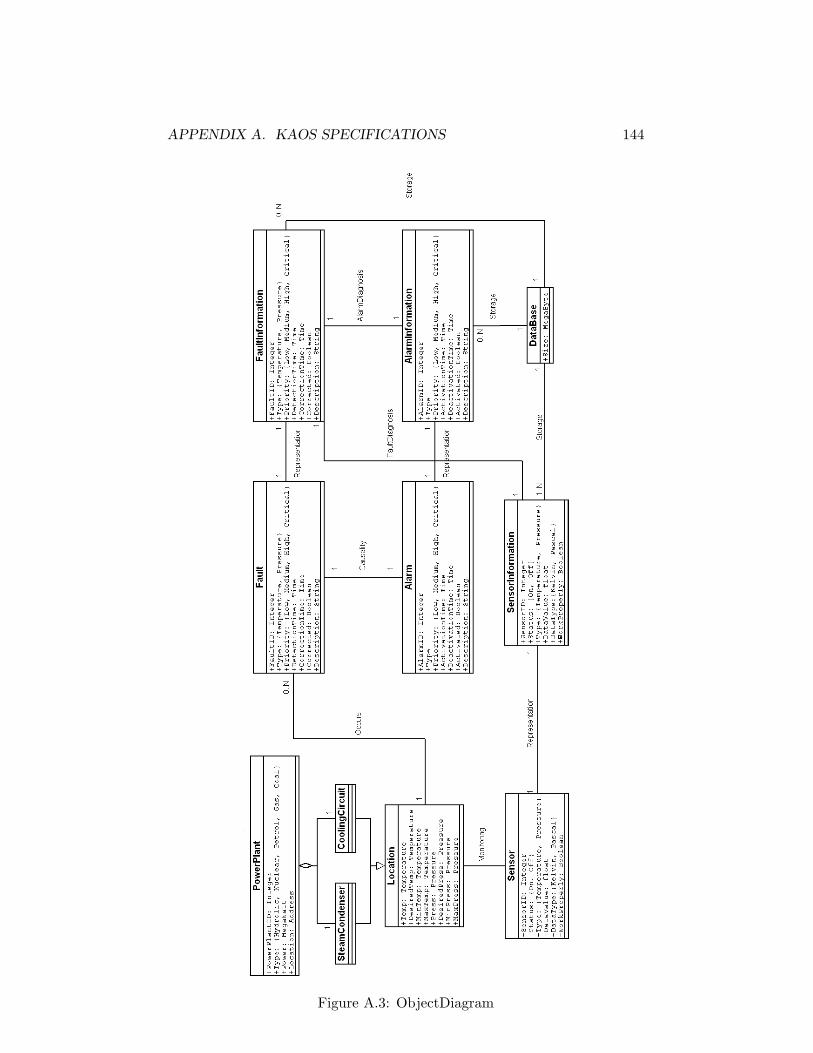
APPENDIX A. KAOS SPECIFICATIONS 144
Figure A.3: ObjectDiagram

APPENDIX A. KAOS SPECIFICATIONS 145
Def An alarm is raised when a fault is detectedHas AlarmID: Integer
Type:Priority: Low, Medium, High, CriticalActivationTime: TimeDeactivationTime: TimeActivated: BooleanDescription: String
DomInvar ActivationTime ¡ DeactivationTimeActivated = true ⇒ DeactivationTime = nullActivated = false ⇒ DeactivationTime 6= null
DomInit Activated = trueDeactivationTime = null
2. Entity AlarmInformation
Def representation of the AlarmHas AlarmID: Integer
Type:Priority: Low, Medium, High, CriticalActivationTime: TimeDeactivationTime: TimeActivated: BooleanDescription: String
DomInvar ActivationTime ¡ DeactivationTimeActivated = true ⇒ DeactivationTime = nullActivated = false ⇒ DeactivationTime 6= null
DomInit Activated = trueDeactivationTime = null
3. Entity CoolingCircuit
Def cools the power plant. It is a component of the powerplant. It accounts for temperature, desired temperature anda range, similarly pressure, a desired pressure and a pressurerange.
IsA LocationHas Inherited from Location
Temp: TemperatureDesiredTemp: TemperatureMinTemp: Temperature
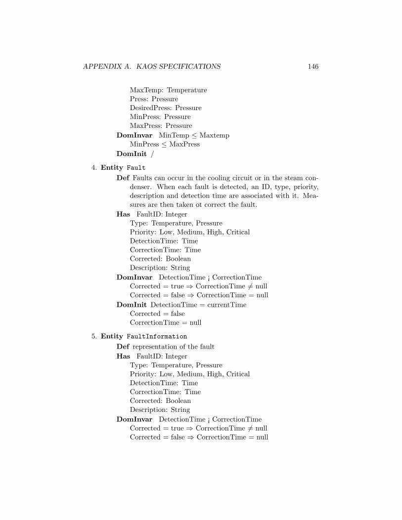
APPENDIX A. KAOS SPECIFICATIONS 146
MaxTemp: TemperaturePress: PressureDesiredPress: PressureMinPress: PressureMaxPress: Pressure
DomInvar MinTemp ≤ MaxtempMinPress ≤ MaxPress
DomInit /
4. Entity Fault
Def Faults can occur in the cooling circuit or in the steam con-denser. When each fault is detected, an ID, type, priority,description and detection time are associated with it. Mea-sures are then taken ot correct the fault.
Has FaultID: IntegerType: Temperature, PressurePriority: Low, Medium, High, CriticalDetectionTime: TimeCorrectionTime: TimeCorrected: BooleanDescription: String
DomInvar DetectionTime ¡ CorrectionTimeCorrected = true ⇒ CorrectionTime 6= nullCorrected = false ⇒ CorrectionTime = null
DomInit DetectionTime = currentTimeCorrected = falseCorrectionTime = null
5. Entity FaultInformation
Def representation of the faultHas FaultID: Integer
Type: Temperature, PressurePriority: Low, Medium, High, CriticalDetectionTime: TimeCorrectionTime: TimeCorrected: BooleanDescription: String
DomInvar DetectionTime ¡ CorrectionTimeCorrected = true ⇒ CorrectionTime 6= nullCorrected = false ⇒ CorrectionTime = null

APPENDIX A. KAOS SPECIFICATIONS 147
DomInit DetectionTime = currentTimeCorrected = falseCorrectionTime = null
6. Entity Location
Def represent a location in the power plantHas Temp: Temperature
DesiredTemp: TemperatureMinTemp: TemperatureMaxTemp: TemperaturePress: PressureDesiredPress: PressureMinPress: PressureMaxPress: Pressure
DomInvar MinTemp ≤ MaxtempMinPress ≤ MaxPress
DomInit /
7. Entity PowerPlant
Def Defines the power plant system. Its components includesteam condenser and cooling circuit.
Has PowerPlantID: IntegerType: Hydrolic, Nuclear, Petrol, Gas, CoalPower: MegaWattLocation: AddressFaultStatus: on,offAlarmStatus: on,off
DomInvar ∀ p:PowerPlantp.faultStatus = on ⇔ (∃ f:Fault,∃ l:Location)(Occurs(f,l) ∧PartOf(l,p) ∧ f.Corrected = falsep.alarmStatus = on⇔ (∃ a:Alarm,∃ l:Location,∃ f:Fault)(Occurs(f,l)∧ PartOf(l,p) ∧ Raise(f,a) ∧ f.Activated = true
DomInit FaultStatus = offAlarmStatus = off
8. Entity Sensor
Def it obtains information from the power plant using physicallyplaced sensors. Informations obtained includes data type andits value. Sensors are also checked to ensure that they areworking correctly
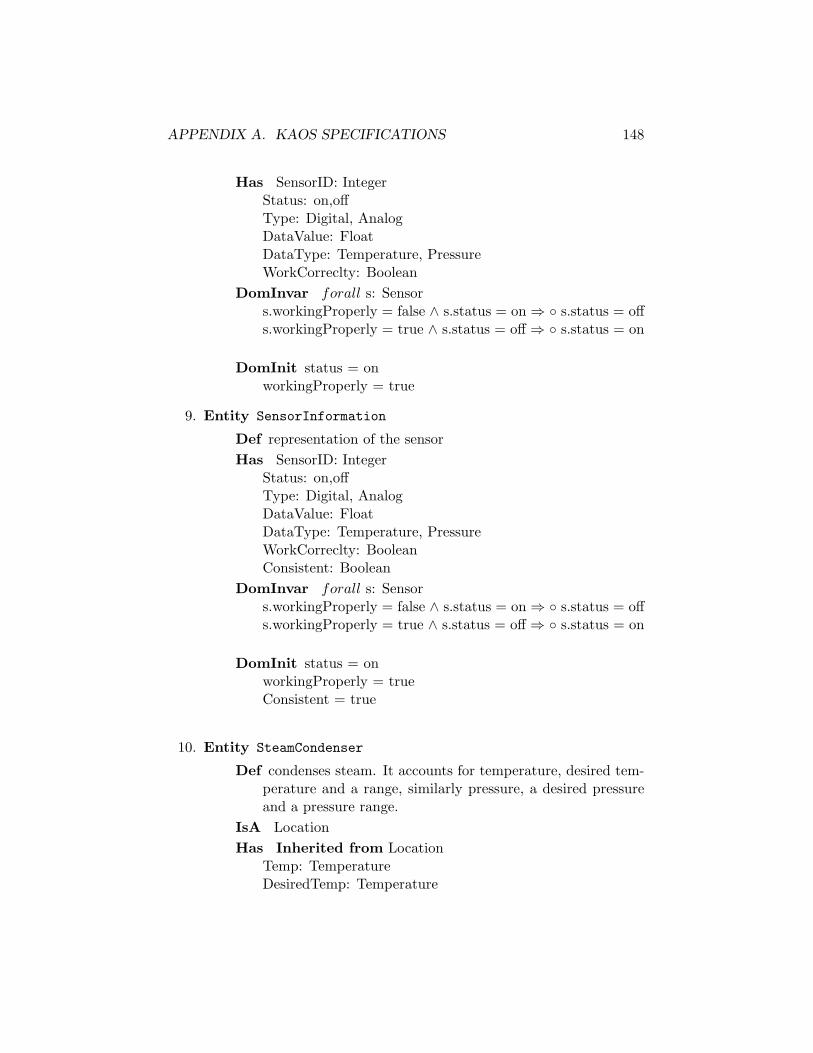
APPENDIX A. KAOS SPECIFICATIONS 148
Has SensorID: IntegerStatus: on,offType: Digital, AnalogDataValue: FloatDataType: Temperature, PressureWorkCorreclty: Boolean
DomInvar forall s: Sensors.workingProperly = false ∧ s.status = on ⇒ ◦ s.status = offs.workingProperly = true ∧ s.status = off ⇒ ◦ s.status = on
DomInit status = onworkingProperly = true
9. Entity SensorInformation
Def representation of the sensorHas SensorID: Integer
Status: on,offType: Digital, AnalogDataValue: FloatDataType: Temperature, PressureWorkCorreclty: BooleanConsistent: Boolean
DomInvar forall s: Sensors.workingProperly = false ∧ s.status = on ⇒ ◦ s.status = offs.workingProperly = true ∧ s.status = off ⇒ ◦ s.status = on
DomInit status = onworkingProperly = trueConsistent = true
10. Entity SteamCondenser
Def condenses steam. It accounts for temperature, desired tem-perature and a range, similarly pressure, a desired pressureand a pressure range.
IsA LocationHas Inherited from Location
Temp: TemperatureDesiredTemp: Temperature

APPENDIX A. KAOS SPECIFICATIONS 149
MinTemp: TemperatureMaxTemp: TemperaturePress: PressureDesiredPress: PressureMinPress: PressureMaxPress: Pressure
DomInvar MinTemp ≤ MaxtempMinPress ≤ MaxPress
DomInit /
A.3 Agents Specifications
The agents are listed by alphabetical order. Figure A.4 shows the respon-sibility assignment of the different agents and Figure A.5 shows the agentsinterfaces in terms of its monitored and controlled variables.
The agents are listed by alphabetical order. Figure A.4 shows the re-sponsibility assignment of the different agents.
1. Agent Acquisition Unit
Def An agent that acquires data from the various sensors mon-itoring the power plant
Has /Monitors Sensor/ID, Sensor/Status, Sensor/Type, Sensor/DataValue,
Sensor/DataTypeControls SensorInformation/ID, SensorInformation/Status, Sen-
sorInformation/Type, SensorInformation/DataValue, Sensor-Information/DataType
ResponsibleFor AnalogDataAcquired, DigitalDataAcquiredDependsOn SensorPerfoms Acquire Analog Data, Acquire Digital Data
2. Agent ALARM
Def An agent that controls the status of the alarmHas AlarmID, Type, Priority, ActivationTime, Deactivation-
Time, Activated, DescriptionMonitors FaultInformation/FaultID, FaultInformation/Type, Fault-
Information/Priority, FaultInformation/DetectionTime, Fault-Information/CorrectionTime, FaultInformation/Corrected, Fault-Information/Description
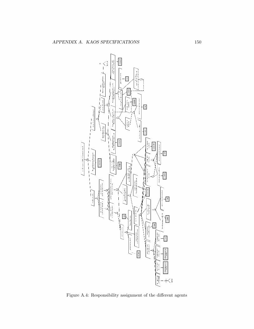
APPENDIX A. KAOS SPECIFICATIONS 150
Figure A.4: Responsibility assignment of the different agents

APPENDIX A. KAOS SPECIFICATIONS 151
Figure A.5: Agent context diagram
APPENDIX A. KAOS SPECIFICATIONS 152
Controls Alarm/AlarmID, Alarm/Type, Alarm/Priority, Alarm/ActivationTime,Alarm/DeactivationTime, Alarm/Activated, Alarm/Description
ResponsibleFor AlarmRaisedWhenFaultInfoTransmitted, Alarm-NotRaisedIfFaultNotDetected, AlarmStatusUpdated
DependsOn PRECONPerfoms Raise Alarm When Alarm Info Transmitted, Update
alarm status, Not Raise Alarm if Fault Not Detected
3. Agent COMM
Def Handles communication between the different objectsHas /Monitors FaultInformation/FaultID, FaultInformation/Type, Fault-
Information/Priority, FaultInformation/DetectionTime, Fault-Information/CorrectionTime, FaultInformation/Corrected, Fault-Information/Description, AlarmInformation/AlarmID, AlarmIn-formation/Type, AlarmInformation/Priority, AlarmInforma-tion/ActivationTime, AlarmInformation/DeactivationTime,AlarmInformation/Activated, AlarmInformation/Description,SensorInformation/SensorID, SensorInformation/Status, Sen-sorInformation/Type, SensorInformation/DataValue, Sensor-Information/DataType, SensorInformation/WorkCorrectly
Controls /ResponsibleFor NoDataIntroduced, NoDataLost, SequenceP-
reserved, DataTransmittedInTime, FaultInfoTransmittedWhen-FaultDetected
DependsOn Sensor, PRECON, ALARM, DatabasePerfoms Transmit Query, Transmit Data to DB, Transmit Fault
Info When Fault Detected
4. Agent DB
Def Stores, updates and returns queries on sensor, fault andalarm information
Has SizeMonitors FaultInformation/FaultID, FaultInformation/Type, Fault-
Information/Priority, FaultInformation/DetectionTime, Fault-Information/CorrectionTime, FaultInformation/Corrected, Fault-Information/Description, AlarmInformation/AlarmID, AlarmIn-formation/Type, AlarmInformation/Priority, AlarmInforma-tion/ActivationTime, AlarmInformation/DeactivationTime,

APPENDIX A. KAOS SPECIFICATIONS 153
AlarmInformation/Activated, AlarmInformation/Description,SensorInformation/SensorID, SensorInformation/Status, Sen-sorInformation/Type, SensorInformation/DataValue, Sensor-Information/DataType, SensorInformation/WorkProperly
Controls Database/SizeResponsibleFor DataCorrectlyUpdated, QueryAnsweredDependsOn Communication, PRECON, ALARM, SensorPerfoms Update Data Correctly, Answer Query
5. Agent Instrumentation Maintenance System(IMS)Def Ensures efficient working of the sensors, checks consistency
in data obtained from the sensorsHas /Monitors SensorInformation/SensorID, SensorInformation/Type,
SensorInformation/DataValue, SensorInformation/DataType,SensorInformation/WorkProperly
Controls SensorInformation/Status, SensorInformation/ConsistentResponsibleFor SanityChecksPerformed, ConsistencyChecksPer-
formedDependsOn SensorPerfoms Perform Sanity Check, Perform Consistency Check
6. Agent OPERATOR
Def Represents user who interacts with the systemHas /Monitors Alarm/AlarmID, Alarm/Type, Alarm/Priority, Alarm/ActivationTime,
Alarm/DeactivationTime, Alarm/Activated, Alarm/DescriptionControls /ResponsibleFor OperatorInteractionsManagedDependsOn /Perfoms Manages Operator Interaction
7. Agent PRECON
Def Detects faults from the data and handles fault statusHas /Monitors SensorInformation/SensorID, SensorInformation/Status,
SensorInformation/Type, SensorInformation/DataValue, Sen-sorInformation/DataType, SensorInformation/WorkCorrectly,SensorInformation/Consistent
APPENDIX A. KAOS SPECIFICATIONS 154
Controls FaultInformation/FaultID, FaultInformation/Type, Fault-Information/Priority, FaultInformation/DetectionTime, Fault-Information/ CorrectionTime, FaultInformation/Corrected,FaultInformation/Description
ResponsibleFor CalculationDone, FaultDetectedWhenCalcu-lationDone, RemedyActionSuggestedWhenFaultDetected, Fault-StatusUpdated
DependsOn DataBasePerfoms Do Calculation, Detect Fault When Calculation is
Done, Suggest Remedy Action When Fault Detected, Up-date Fault Status
8. Agent Sensor
Def Physical sensors provide plant informationHas SensorId, Status, Type, DataValue, DataType, WorkCor-
rectlyMonitors SteamCondensor/Temperature, SteamCondensor/DesiredTemp,
SteamCondensor/MinTemp, SteamCondensor/MaxTemp, Steam-Condensor/Pressure, SteamCondensor/DesiredPress, Steam-Condensor/ MinPress, SteamCondensor/MaxPress, Cooling-Circuit/Temperature, CoolingCircuit /DesiredTemp, Cool-ingCircuit /MinTemp, CoolingCircuit /MaxTemp, Cooling-Circuit /Pressure, CoolingCircuit /DesiredPress, CoolingCir-cuit /MinPress, CoolingCircuit /MaxPress, Sensor/Status,
Controls Sensor/SensorID, Sensor/Type, Sensor/DataValue, Sen-sor/DataType
ResponsibleFor Maintain[SensorCorrectValue]
A.4 Operations specifications
Operations are listed by alphabetical order.
1. Operation AcquireAnalogData
Def Acquire the data coming from an analog deviceInput s:Sensor,si:SensorInformationOutput si:SensorInformation/ValueDomPre s.value 6= si.valueDomPost s.value = si.value

APPENDIX A. KAOS SPECIFICATIONS 155
ReqTrig for AnalogDataAcquireds.value 6= si.value S=9s s.Type = ’Analog’ ∧ s.ID=si.ID ∧s.Value 6= si.Value
PerformedBy Acquisistion Unit
2. Operation AcquireDigitalData
Def Acquire the data coming from an digital deviceInput s:Sensor,si:SensorInformationOutput si:SensorInformation/ValueDomPre s.value 6= si.valueDomPost s.value = si.valueReqTrig For DigitalDataAcquired
s.value 6= si.value S=9s s.Type = ’Digital’ ∧ s.ID = si.ID ∧s.Value 6= si.Value
PerformedBy Acquisition Unit
3. Operation AnswerAlarmQuery
Def Answer to a alarm queryInput a: AlarmOutput ai: AlarmInformationDomPre ¬ Transmitted(ai,DB,ALARM)DomPost Transmitted(ai,DB,ALARM)ReqTrig For AlarmQueryAnswered
¬ Transmitted(ai,DB,ALARM) S=1s Transmitted(a,ALARM,DB)∧Query(a)∧ Stored(ai) ∧ ai.ID = a.ID ∧ ¬ Transmitted(ai,DB,ALARM)
PerformedBy DB
4. Operation AnswerSensorQuery
Def Answer to a sensor queryInput s: SensorOutput si: SensorInformationDomPre ¬ Transmitted(si,DB,PRECON)DomPost Transmitted(si,DB,PRECON)ReqTrig For SensorQueryAnswered
¬ Transmitted(si,DB,PRECON) S=1s Transmitted(s,PRECON,DB)∧Query(s)∧ Stored(si) ∧ si.ID = s.ID ∧ ¬ Transmitted(si,DB,PRECON)
PerformedBy DB
APPENDIX A. KAOS SPECIFICATIONS 156
5. Operation Calculate
Def calculate all needed things in order to detect faultsInput si: SensorInformationOutput /DomPre ¬ CalculationDoneDomPost CalculationDoneReqTrig For CalculationDone
¬ CalculationDone S=1s Transmitted(si,DB,PRECON) ∧ ¬CalculationDone
PerformedBy PRECON
6. Operation DetectFault
Def detect FaultInput f: Fault, l: LocationOutput /DomPre ¬ Detected(f,l)DomPost Detected(f,l)ReqTrig For FaultDetectedWhenCalculationDone
¬ Detected(f,l) S=1s CalculationDone ∧ Occurs(f,l) ∧ ¬ De-tected(f,l)
PerformedBy PRECON
7. Operation RaiseAlarm
Def Raise the alarmInput fi: FaultInformation, a: AlarmOutput a: AlarmDomPre ¬ Raise(fi,a)DomPost Raise(fi,a)ReqTrig For AlarmRaisedWhenFaultInformationTransmitted
¬ Raise(fi,a) S=1s Transmitted(fi,PRECON, ALARM) ∧ ¬Raise(fi,a)
PerformedBy ALARM
8. Operation SwitchAlarmStatusOff
Def switch the Alarm Status offInput a: Alarm, fi: FaultInformation, PowerPlantOutput PowerPlant/AlarmStatus

APPENDIX A. KAOS SPECIFICATIONS 157
DomPre PowerPlant.AlarmStatus = onDomPost PowerPlant.AlarmStatus = offReqPre For AlarmStatusUpdated
¬ Raise(fi,a)Operationalizes AlarmStatusUpdatedPerformedBy ALARM
9. Operation SwitchAlarmStatusOn
Def switch the Alarm Status onInput a: Alarm, fi: FaultInformation, PowerPlantOutput PowerPlant/AlarmStatusDomPre PowerPlant.AlarmStatus = offDomPost PowerPlant.AlarmStatus = onReqTrig For AlarmStatusUpdated
Raise(fi,a)Operationalizes AlarmStatusUpdatedPerformedBy ALARM
10. Operation SwitchFaultStatusOff
Def switch the Fault Status offInput f: Fault, l: Location, PowerPlantOutput PowerPlant/FaultStatusDomPre PowerPlant.FaultStatus = onDomPost PowerPlant.FaultStatus = offReqPre For FaultStatusUpdated
¬ Detected(f,l)PerformedBy PRECON
11. Operation SwitchFaultStatusOn
Def switch the Fault Status onInput f: Fault, l: Location, PowerPlantOutput PowerPlant/FaultStatusDomPre PowerPlant.FaultStatus = offDomPost PowerPlant.FaultStatus =onReqTrig For FaultStatusUpdated
Detected(f,l)PerformedBy PRECON
APPENDIX A. KAOS SPECIFICATIONS 158
12. Operation SwitchSensorOff
Def Turn the sensor offInput s:SensorOutput s:Sensor/StatusDomPre s.Status = ’on’DomPost s.Status = ’off’ReqTrig For SanityCheckPerformed
¬ s.WorkingProperlyPerformedBy ACQUISITION UNIT
13. Operation SwitchSensorOn
Def Turn the sensor onInput s:SensorOutput s:Sensor/StatusDomPre s.Status = ’off’DomPost s.Status = ’on’ReqPre For SanityCheckPerformed
s.WorkingProperlyOperationalizes SanityCheckPerformedPerformedBy ACQUISITION UNIT
14. Operation TransmitAlarmData
Def Transmit the alarm data to the DataBaseInput fi: FaultInformation, a: Alarm, ai: AlarmInformation,
ad: AlarmDiagnososisOutput /DomPre ¬ Transmitted(ai,ALARM,DB) ∨ ¬ Transmitted(ad,ALARM,DB)
∨ ¬ Concerns(ad,fi,ai)DomPost Transmitted(ai,ALARM,DB) ∧ Transmitted(ad,ALARM,DB)
∧ Concerns(ad,fi,ai)ReqTrig For AlarmDataTransmitted
¬ Transmitted(ai,ALARM,DB) ∨ ¬ Transmitted(ad,ALARM,DB)∨ ¬ Concerns(ad,fi,ai) S=1s Raise(fi,a) ∧ a.ID = ai.ID ∧
(¬
Transmitted(ai,ALARM,DB) ∨ ¬ Transmitted(ad,ALARM,DB)∨ ¬ Concerns(ad,fi,ai)
)PerformedBy COMMUNICATION

APPENDIX A. KAOS SPECIFICATIONS 159
15. Operation TransmitAlarmQuery
Def transmit a alarm query to the DataBaseInput a: AlarmOutput /DomPre ¬ Transmitted(a,ALARM,DB)DomPost Transmitted(a,ALARM,DB)ReqTrig For AlarmQuerryTransmitted
¬ Transmitted(a,ALARM,DB) S=1s Query(a) ∧ ¬ Transmit-ted(a,ALARM,DB)
PerformedBy COMMUNICATION
16. Operation TransmitDiagnosisData
Def Transmit the data concerning the diagnosis of a fault tothe DataBase
Input f: Fault, l: Location, fi: FaultInformation, si: SensorIn-formation, fd: FaultDiagnosis
Output /DomPre ¬ Transmitted(fi,PRECON,DB) ∨ ¬ Transmitted(ad,PRECON,DB)
∨ ¬ Concerns(ad,si,fi)DomPost Transmitted(fi,PRECON,DB) ∧ Transmitted(ad,PRECON,DB)
∧ Concerns(ad,si,fi)ReqTrig For DiagnosisDataTransmitted
¬ Transmitted(fi,PRECON,DB) ∨ ¬ Transmitted(ad,PRECON,DB)∨ ¬ Concerns(ad,si,fi) S=1s Detected(f,l) ∧ f.ID = fi.ID ∧
(¬
Transmitted(fi,PRECON,DB) ∨ ¬ Transmitted(ad,PRECON,DB)∨ ¬ Concerns(ad,si,fi)
)PerformedBy COMMUNICATION
17. Operation TransmitFaultInformation
Def Transmit Fault Information to The ALARM Managementunit
Input f: Fault, l: Location, fi: FaultInformationOutput /DomPre ¬ Transmitted(fi,PRECON, ALARM)DomPost Transmitted(fi,PRECON, ALARM)ReqTrig For FaultInformationTransmittedWhenFaultDetected
¬ Transmitted(fi,PRECON, ALARM) S=1s Detected(f,l) ∧f.ID = fi.ID ∧ ¬ Transmitted(fi,PRECON, ALARM)
APPENDIX A. KAOS SPECIFICATIONS 160
PerformedBy COMMUNICATION
18. Operation TransmitSensorData
Def Transmit the data to the DataBaseInput si: SensorInformationOutput /DomPre ¬ Transmitted(si,ACQUISITION,DB)DomPost Transmitted(si,ACQUISITION,DB)ReqTrig For SensorDataTransmitted
¬ Transmitted(si,ACQUISITION,DB) S=1s si.Consistent ∧¬ Transmitted(si,ACQUISITION,DB)
PerformedBy COMMUNICATION
19. Operation TransmitSensorQuery
Def transmit a sensor query to the DataBaseInput s: SensorOutput /DomPre ¬ Transmitted(s,PRECON,DB)DomPost Transmitted(s,PRECON,DB)ReqTrig For SensorQuerryTransmitted
¬ Transmitted(s,PRECON,DB) S=1s Query(s) ∧ ¬ Trans-mitted(s,PRECON,DB)
PerformedBy COMMUNICATION
20. Operation UnValidateData
Def Unvalidate the sensor data if they are not considered plau-sible
Input si: SensorInformationOutput si: SensorInformation/ConsistentDomPre si.ConsistentDomPost ¬ si.ConsistentReqTrig For ConsistencyChecksPerformed
(si.DataType = ’Temperature’ ∧ (si.Value < minTemp ∨si.Value > maxTemp))∨ (si.DataType = ’Pressure’ ∧ (si.Value < minPres ∨ si.Value> maxPres))
PerformedBy ACQUISITION UNIT

APPENDIX A. KAOS SPECIFICATIONS 161
21. Operation UpdateAlarmData
Def Update Alarm data in the DataBaseInput ai: AlarmInformation, ad: AlarmDiagnosisOutput /DomPre ¬ Stored(ai) ∨ ¬ Stored(ad)DomPost Store(ai) ∧ Stored(ad)ReqTrig For AlarmDataCorrectlyUpdated
¬ Stored(ai) ∨ ¬ Stored(ad) S=1s Transmitted(ai,ALARM,DB)∧ Transmitted(ad,ALARM,DB) ∧ ( ¬ Stored(ai) ∨ ¬ Stored(ad))
PerformedBy
22. Operation UpdateDiagnosisData
Def Store the data concerning a detected fault in the DataBaseInput fi: SensorInformation, fd: FaultDiagnosisOutput /DomPre ¬ Stored(fi) ∨ ¬ Stored(fd)DomPost Stored(fi) ∧ Stored(fd)ReqTrig For DiagnosisDataUpdated
¬ Stored(fi) ∨ ¬ Stored(fd) S=1s Transmitted(fd,PRECON,DB)∧ Transmitted(fi,PRECON,DB) ∧ (¬ Stored(fi) ∨ ¬ Stored(fd))
PerformedBy DB
23. Operation UpdateSensorData
Def Update the data in the DataBaseInput si: SensorInformationOutput /DomPre ¬ Stored(si)DomPost Stored(si)ReqTrig For SensorDataUpdated
¬ Stored(si) S=1s Transmitted(si,ACQUISITION,DB)∧ ¬ Stored(si)PerformedBy DB
24. Operation ValidateData
Def Validate the sensor data if they are considered plausibleInput si: SensorInformationOutput si: SensorInformation/Consistent
APPENDIX A. KAOS SPECIFICATIONS 162
DomPre ¬ si.ConsistentDomPost si.ConsistentReqPre For ConsistencyChecksPerformed
(si.DataType = ’Temperature’ ∧ (minTemp ≤ si.Value ≤maxTemp))∨ (si.DataType = ’Pressure’ ∧minPres≤ si.Value≤maxPres))
PerformedBy ACQUISITION UNIT
A.5 Modifications resulting from the obstacle anal-ysis
Figure A.6 shows the modifications brought to the NFG diagram. Modifi-cations are highlighted through thicker lines. The following goals have beenadded:
• Safety goals
Goal Avoid[AllSensorOff]
Def There must always be at least one sensor workingConcerns SensorFormalDef � ¬ ∀ s:Sensor
s.status=off
Goal Avoid[LocationNotMonitored]
Def Every location must always be monitored by at least a sen-sor
Concerns SensorFormalDef � ¬ ∃ l:Location, ∀ s:Sensor
¬ Monitor(s,l)
• Reliability goals
Goal Maintain[FaultTolerantCommunication(PRECON,ALARM)]
Def The communication between PRECON and ALARM shouldbe fault-tolerant
• Accuracy Goals
Goal Maintain[AccurateData(Acquisition Unit,IMS)]

APPENDIX A. KAOS SPECIFICATIONS 163
Figure A.6: Modifications brought to the NFG diagram after the obstacleanalysis
APPENDIX A. KAOS SPECIFICATIONS 164
Def The Sensor informations possessed by the agents Acquisi-tion Unit an IMS should always be equal
Concerns SensorInformation
Goal Maintain[AccurateRepresentation(ai,a)]
Def The software representation of an alarm should always re-flect the alarm state
Concerns Alarm, AlarmInformationFormalDef ∀ a:Alarm, ∃! ai:AlarmInformation
a.id=ai.id ⇒ � ( a.Type = ai.Type ∧ a.Priority = ai.Priority∧ a.ActivationTime = ai.ActivationTime∧ a.CorfectionTime = ai.CorrectionTime∧ a.Corrected = ai.Corrected∧ a.Description = ai.Description )
Goal Maintain[AccurateRepresentation(fi,f)]
Def The software representation of a Fault should always reflectthe fault state
Concerns Fault, FaultInformationFormalDef ∀ f:Fault, ∃! fi:FaultInformation
f.id=fi.id ⇒ � ( f.Type = fi.Type ∧ f.Priority = fi.Priority∧f.DetectionTime = fi.DetectionTime∧ f.CorfectionTime = fi.CorrectionTime∧ f.Corrected = fi.Corrected∧ f.Description = fi.Description )
Goal Maintain[AccurateRepresentation(si,s)]
Def The software representation of a sensor should always re-flect the sensor state
Concerns Fault, FaultInformationFormalDef ∀ s:Sensor, ∃! si:SensorInformation
s.id=si.id ⇒ � ( s.Status=si.Status ∧ s.Type = si.Type∧ s.DataValue = si.DataValue ∧ s.DataType = si.DataType∧ s.WorkingCorrectly = si.WorkingCorrectly )

Appendix B
Architectural Prescriptions
B.1 Initial Prescriptions
Preskriptor Specification: PowerPlant Monitoring System
Problem Goals Specifications: PowerPlant Monitoring Process
Components:
1. Component PowerPlantSupervisingSystem[1,1]Type ProcessingConstraints PerformancOfThePlantMonitoredComposed of PRECON
ALARMDataBaseCommunication
Uses /
2. Component PRECON[1,1]Type ProcessingConstraints FaultDetected
RemedyActionSuggestedPeriodicalChecksPerformed&ReportWritten
Composed of FaultDetectionEngineFaultInformationFaultDiagnosis
165

APPENDIX B. ARCHITECTURAL PRESCRIPTIONS 166
SensorInformationSensorConnect
Uses /
3. Component ALARM[1,1]Type ProcessingConstraints AlarmCorrectlyManaged
AlarmRaisedIffFaultDetectedAlarmTraced
Composed of AlarmManagerAlarmInformationAlarmDiagnosisInteractionManager
Uses /
4. Component Database[1,1]Type ProcessingConstraints CorrectDataPersistentlyStoredComposed of QueryManager
UpdateManagerUses /
5. Component Communication[1,1]Type ConnectorConstraints NoDataIntroduced
NoDataLostSequencePreservedDataTransmittedInTimeDataTransmittedToTheDBQueryTransmittedFaultInformationTransmittedWhenFaultDetected
Composed of UpdateDBConnectQueryDBConnectFaultDetectionEngineAlarmManagerConnect
Uses /
6. Component FaultDetectionEngine[1,1]Type ProcessingConstraints CalculationDone
FaultDetectedWhenCalculationDoneFaultStatusUpdated

APPENDIX B. ARCHITECTURAL PRESCRIPTIONS 167
CheckPerformedWhenDataAcquiredReportWrittenWhenCheckPerformed
Composed of /Uses SensorConnect to interract with SensorInformation
FaultDetectionEngineAlarmManagerConnect to interractwith AlarmManagerUpdateDBConnect to interact with UpdateManager
7. Component FaultInformation[0,n]Type DataConstraints FaultInformationTransmittedWhenFaultDetectedComposed of /Uses FaultDetectionEngineAlarmManagerConnect to inter-
ract with AlarmManagerUpdateDBConnect to interact with UpdateManager
8. Component FaultDiagnosis[0,n]Type DataConstraints DiagnosisWritten
ComputedVariablesStoredComposed of /Uses UpdateDBConnect to interact with DBUpdateMan-
ager
9. Component SensorInformation[l,n]1
Type DataConstraints AnalogDataAcquired
DigitalDataAcquiredSanityCheckPerformedConsistencyCheck
Composed of /Uses UpdateDBConnect to interact with DB
SensorConnect to interact with FaultDetectionEngine
10. Component SensorConnect[1,1]Type ConnectorConstraints DataAcquiredFromTheFieldComposed of /
1To achieve the non-functional goal Avoid[LocationNotMonitored] there must be atleast l sensors where l is the number of locations

APPENDIX B. ARCHITECTURAL PRESCRIPTIONS 168
Uses /
11. Component UpdateDBConnect[1,1]Type ConnectorConstraints Secure
TimeConstraint = 2sComposed of /Uses /
12. Component QueryDBConnect[1,1]Type ConnectorConstraints TimeConstraint = 5sComposed of /Uses /
13. Component FaultDetectionEngineAlarmManagerConnect[1,1]Type ConnectorConstraints Maintain[FaultTolerantCommunication(PRECON,ALARM)]
SecureTimeConstraint = 1s
Composed of /Uses /
14. Component AlarmManager[1,1]Type ProcessingConstraints AlarmRaisedWhenFaultInformationTransmitted
FaultInformationTransmittedAlarmStatusUpdatedAlarmNotRaisedIfFaultNotDetected
Composed of /Uses FaultDetectionEngineAlarmManagerConnect to inter-
ract with FaultDetectionEngine UpdateDBConnect to in-teract with UpdateManager
15. Component AlarmInformation[0,n]Type DataConstraints AlarmInformationStoredWhenAlarmRaisedComposed of /Uses UpdateDBConnect to interact with UpdateManager
16. Component AlarmDiagnosis[0,n]
APPENDIX B. ARCHITECTURAL PRESCRIPTIONS 169
Type DataConstraints DiagnosisWrittenComposed of /Uses UpdateDBConnect to interact with UpdateManager
17. Component InteractionManager[1,1]Type ProcessingConstraints OperatorInteractionManagedComposed of /Uses QueryDBConnect to interact with QueryManager
18. Component QueryManager[1,1]Type ProcessingConstraints QueryAnswered
DataQueriedUponUserRequestAlarmInformationProvidedUponUserRequestDataAcquired
Composed of /Uses QueryDBConnect to interact with InteractionMan-
ager
19. Component UpdateManager[1,1]Type ProcessingConstraints DataCorrectlyUpdated DataUpdatedIfConsis-
tentComposed of /Uses SensorConnect to interact with SensorInformation
UpdateDBConnect to interact with FaultDetectionEngineUpdateDBConnect to interact with FaultDiagnosisUpdateDBConnect to interact with AlarmManagerUpdateDBConnect to interact with AlarmDiagnosis
B.2 Prescriptions resulting from step 4
Definition of the new constraints
1. Constraint Achieve[SwitchInCaseOfFailure]
Informal Def : Every time a component fails (PRECON or ALARM),the copy should take te relay

APPENDIX B. ARCHITECTURAL PRESCRIPTIONS 170
Formal Def : ∀ x:Component (x.type = PRECON ∨ x.type =ALARM ) ∧ x.Status = failure ⇒ ∃ y:Component x.type =y.type ∧ y.Status = working ∧ ◦ ( y.Work ∧ ¬ x.Work )
2. Constraint Maintain[OneActiveComponent]
Informal Def : Only one component (PRECON or ALARM)should be working at a time
Formal Def : ∀ x:Component ( x.type = PRECON ∨ x.type =ALARM ) ∧ x.Work ⇒ ¬ ∃ y:Component x.type=y.type ∧¬ x = y ∧ y.Work
3. Constraint Maintain[NoPrecedenceRelation]
Informal Def : There is no difference in importance betweenthe copies. So the switch should only occur in case of afailure
Formal Def : • ¬ x.Work ∧ x.Work ⇒ ∃ y • y.status=working∧ y.status=failure ∧ x.type=y.type ∧ ¬ x = y ∧ x ≡ y
4. Constraint Achieve[TransparencyOfSwitching]
Informal Def : A failure of PRECON or ALARM should notaffect the other. The other should continue to work fine
Formal Def : ∃ x:Component • x.Status = working ∧ x.Status=failure⇒ ( ∀ y:Component x.type 6= y.type ∧ • y.Satus=working ⇒y.Status =woking )
Prescriptions of the modified components
The modifications are highlighted in bold.
1. Component FaultDetectionEngine[2,2]Type ProcessingConstraints CalculationDone
FaultDetectedWhenCalculationDoneFaultStatusUpdatedCheckPerformedWhenDataAcquiredReportWrittenWhenCheckPerformed
Composed of /Uses SensorConnect to interract with SensorInformation
FaultDetectionEngineAlarmManagerConnect to interract withAlarmManagerUpdateDBConnect to interact with UpdateManager

APPENDIX B. ARCHITECTURAL PRESCRIPTIONS 171
2. Component AlarmManager[2,2]
Type ProcessingConstraints AlarmRaisedWhenFaultInformationTransmitted
FaultInformationTransmittedAlarmStatusUpdatedAlarmNotRaisedIfFaultNotDetected
Composed of /Uses FaultDetectionEngineAlarmManagerConnect to interract
with FaultDetectionEngine UpdateDBConnect to interact withUpdateManager
3. Component FaultDetectionEngineAlarmManagerConnect[1,1]
Type ConnectorConstraints Maintain[FaultTolerantCommunication(PRECON,ALARM)]
SecureTimeConstraint = 1sAchieve[SwitchInCaseOfFailure]Maintain[OneActiveComponent]Maintain[NoPrecedenceRelation]Achieve[TransparencyOfSwitching]
Composed of /Uses /
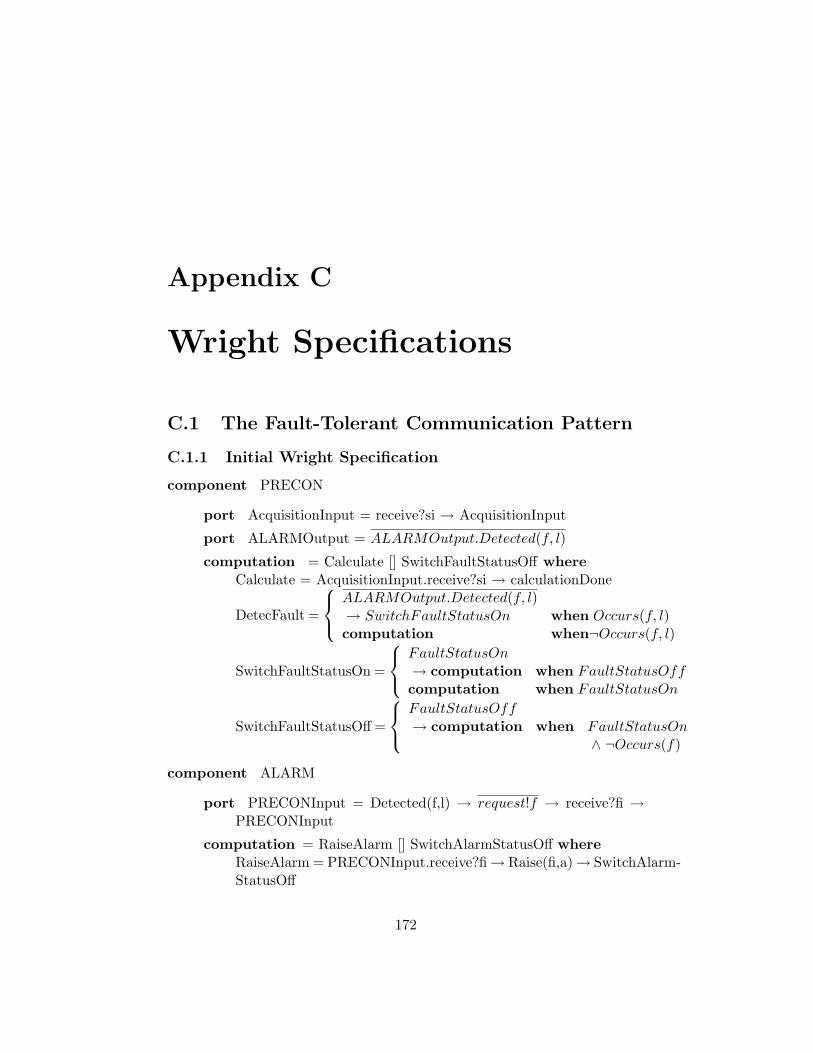
Appendix C
Wright Specifications
C.1 The Fault-Tolerant Communication Pattern
C.1.1 Initial Wright Specification
component PRECON
port AcquisitionInput = receive?si → AcquisitionInput
port ALARMOutput = ALARMOutput.Detected(f, l)
computation = Calculate [] SwitchFaultStatusOff whereCalculate = AcquisitionInput.receive?si → calculationDone
DetecFault =
ALARMOutput.Detected(f, l)→ SwitchFaultStatusOn when Occurs(f, l)computation when¬Occurs(f, l)
SwitchFaultStatusOn =
FaultStatusOn→ computation when FaultStatusOffcomputation when FaultStatusOn
SwitchFaultStatusOff =
FaultStatusOff→ computation when FaultStatusOn
∧ ¬Occurs(f)
component ALARM
port PRECONInput = Detected(f,l) → request!f → receive?fi →PRECONInput
computation = RaiseAlarm [] SwitchAlarmStatusOff whereRaiseAlarm = PRECONInput.receive?fi→ Raise(fi,a)→ SwitchAlarm-StatusOff
172

APPENDIX C. WRIGHT SPECIFICATIONS 173
SwitchAlarmStatusOn =
AlarmStatusOn→ computation when AlarmStatusOffcomputation when AlarmStatusOn
SwitchAlarmStatusOff =
AlarmStatusOff→ computation when AlarmStatusOn
∧¬Raise(fi, a)
constraints ∀ fi:FaultInformation, ∃ !a:AlarmTransmitted(fi,PRECON,ALARM) ⇒ ♦≤1s Raise(fi,a)
connector Pull-Dataflow
role Producer = dataReady → Producer[] request?x → send!x → Producer u §
role Consumer = dataReady → request!x → receive?x → Consumer[] §
glue = Producer.dataReady→ Consumer.dataReady → Consumer.request!x→ Producer.request?x→ Producer.send!x→ Consumer.reveive?x→ glue [] §
instances Precon: PRECONAlarm: ALARMPrecon2Alarm: PullDataflow
attachements Precon.ALARMOutput as Precon2Alarm.ProducerAlarm.PRECONInput as Precon2Alarm.Consumer
C.1.2 Resulting Wright Specification
component PRECON
port AcquisitionInput = receive?si → AcquisitionInput
port ALARMOutput = ALARMOutput.Detected(f, l)
port Copylink={
isAlive → ImAlive → Copylink[] reset → sleep → wakeUp → Copylink
computation =
compute[] reset → sleep → wakeUp → computation[] Copylink.isAlive → Copylink.ImAlive → computation where
compute = Calculate [] SwitchFaultStatusOffCalculate = AcquisitionInput.receive?si → calculationDone

APPENDIX C. WRIGHT SPECIFICATIONS 174
DetecFault =
ALARMOutput.Detected(f, l)→ SwitchFaultStatusOn when Occurs(f, l)computation when¬Occurs(f, l)
SwitchFaultStatusOn =
FaultStatusOn→ computation when FaultStatusOffcomputation when FaultStatusOn
SwitchFaultStatusOff =
FaultStatusOff→ computation when FaultStatusOn
∧ ¬Occurs(f)
component ALARM
port PRECONInput = Detected(f,l) → request!f → receive?fi →PRECONInput
port Copylink={
isAlive → ImAlive → Copylink[] reset → sleep → wakeUp → Copylink
computation =
compute[] reset → sleep → wakeUp → computation[] Copylink.isAlive → Copylink.ImAlive → computation where
compute= RaiseAlarm [] SwitchAlarmStatusOffRaiseAlarm = PRECONInput.receive?fi→ Raise(fi,a)→ SwitchAlarm-StatusOff
SwitchAlarmStatusOn =
AlarmStatusOn→ computation when AlarmStatusOffcomputation when AlarmStatusOn
SwitchAlarmStatusOff =
AlarmStatusOff→ computation when AlarmStatusOn
∧¬Raise(fi, a)
constraints ∀ fi:FaultInformation, ∃ !a:AlarmTransmitted(fi,PRECON,ALARM) ⇒ ♦≤1s Raise(fi,a)
connector Pull-Dataflow
role ProducerCopy1 = dataReady → Producer[] request?x → send!x → Producer u §
role ProducerCopy2 = dataReady → Producer[] request?x → send!x → Producer u §
role ConsumerCopy1 = dataReady→ request!x→ receive?x→ Con-sumer [] §

APPENDIX C. WRIGHT SPECIFICATIONS 175
role ConsumerCopy2 = dataReady→ request!x→ receive?x→ Con-sumer [] §
glue =
ProducerCopy1.dataReady[]ProducerCopy2.dataReady
→ (ConsumerCopy1.dataReady ‖ ConsumerCopy2.dataReady)→ (ConsumerCopy1.request!x [] ConsumerCopy2.request!x)→ (ProducerCopy1.request?x ‖ ProducerCopy2.request?x)→ (ProducerCopy1.send!x [] ProducerCopy2.send!x)→ (ConsumerCopy1.reveive?x ‖ ConsumerCopy2.reveive?x)→ glue [] §
connector copyConnect
role Copy1,2
glue = Copy1
Copy1 = Copy1.isAlive →{
Copy1 when Copy1.ImAlive within t sCopy1Failure when ¬Copy1.ImAlive within t s
Copy2 = Copy2.isAlive →{
Copy2 when Copy2.ImAlive within t sCopy2Failure when ¬Copy2.ImAlive within t s
Copy1Failure ={
Copy1.reset → Copy2.wakeUp
→ Copy1.sleep → Copy2
Copy2Failure ={
Copy2.reset → Copy1.wakeUp
→ Copy2.sleep → Copy1
instances Precon1, Precon2: PRECONAlarm1, Alarm2: ALARMPrecon2Alarm: PullDataflowAlam2Alarm, Precon2Precon: copyConnect
attachements Precon1.ALARMOutput as Precon2Alarm.ProducerCopy1
Precon2.ALARMOutput as Precon2Alarm.ProducerCopy2
Precon1.CopyLink as Precon2Precon.Copy1
Precon2.CopyLink as Precon2Precon.Copy2
Alarm1.PRECONInput as Precon2Alarm.ConsumerCopy1
Alarm2.PRECONInput as Precon2Alarm.ConsumerCopy2
Alarm1.CopyLink as Alarm2Alam.Copy1
Alarm2.CopyLink as Alarm2Alam.Copy2

APPENDIX C. WRIGHT SPECIFICATIONS 176
C.2 The Observer Pattern
C.2.1 Initial Wright Specification
component Acquisition Unit
port ToIMS = transmitted!si → ToIMSport FromIMS = receive?si → FromIMScomputation = (AcquireAnalog [] AcquireDigital) [] Update where
AcquireAnalog =
Update(si.value)→ ToIMS.transmitted!si→ computation when s.value 6= si.value
∧si.Type = Analog∧si.Status = on
AcquireDigital =
Update(si.value)→ ToIMS.transmitted!si→ computation when s.value 6= si.value
∧si.Type = Digital∧si.Status = on
Update = FromIMS.receive?si→ Synchronize(si)→ computation
component IMS
port ToAcquisition = transmitted!si → ToAcquisitionport FromAcquisition = receive?si → FromAcquisition
computation ={
SwitchSensorOff [] SwitchSensorOn[]V alidateData [] UnV alidateData[]Update where
SwitchSensorOff =
TurnOff(s) → Update(si.status)→ ToAcquisition.transmitted!si when ¬s.WorkingProperly
∧s.Status = on
SwitchSensorOn =
TurnOn(s) → Update(si.status)→ ToAcquisition.transmitted!si when s.WorkingProperly
∧s.Status = off
ValidateData=
Update(si.consistent)→ ToAcquisition.transmitted!si when s.value /∈ PossibleRange
∧¬si.consistent
UnValidateData=
Update(si.consistent)→ ToAcquisition.transmitted!si when s.value ∈ PossibleRange
∧si.consistent
Update = FromAcquisition.receive?si→ Synchronize(si)→ computation

APPENDIX C. WRIGHT SPECIFICATIONS 177
connector Push-Dataflow
role Producer = provide!x → Producer u §role Consumer = retrieve?x → Consumer [] §glue = Producer.provide!x → Consumer.retrieve?x → glue [] §
instances Acq: Acquisition UnitIms: IMSIms2Acq: PushDataflowAcq2Ims: PushDataflow
attachements Acq.ToIMS as Acq2Ims.ProducerIms.FromAcquisition as Acq2Ims.ConsumerAcq.FromIMS as Ims2Acq.ConsumerIms.ToAcquisisition as Ims2Acq.Producer
C.2.2 Resulting Wright Specification
component Acquisition Unit
port SubjectLink ={
SetState!x → SubjectLink[] Notify → GetState!si → SendState?si → SubjectLink
computation = compute [] Update wherecompute= AcquireAnalog [] AcquireDigital
AcquireAnalog =
Update(si.value)→ SubjectLink.SetState!si→ computation when s.value 6= si.value
∧si.Type = Analog∧si.Status = on
AcquireDigital =
Update(si.value)→ SubjectLink.SetState!si→ computation when s.value 6= si.value
∧si.Type = Digital∧si.Status = on
Update =
Subject.Notify → Subject.GetState!x→ Subject.SendState?y → SynchronizeV alue→ computation
component IMS

APPENDIX C. WRIGHT SPECIFICATIONS 178
port SubjectLink ={
SetState!x → SubjectLink[] Notify → GetState!si → SendState?si → SubjectLink
computation = compute [] Update where
compute ={
SwitchSensorOff [] SwitchSensorOn[]V alidateData [] UnV alidateData
SwitchSensorOff =
TurnOff(s) → Update(si.status)→ SubjectLink.SetState!si when ¬s.WorkingProperly
∧s.Status = on
SwitchSensorOn =
TurnOn(s) → Update(si.status)→ SubjectLink.SetState!si when s.WorkingProperly
∧s.Status = off
ValidateData=
Update(si.consistent)→ SubjectLink.SetState!si when s.value /∈ PossibleRange
∧¬si.consistent
UnValidateData=
Update(si.consistent)→ SubjectLink.SetState!si when s.value ∈ PossibleRange
∧si.consistent
Update =
Subject.Notify → Subject.GetState!x→ Subject.SendState?y → SynchronizeV alue→ computation
component Subject
port Observer1,2Link ={
SetState?x → Notify → Observer1,2Link[] GetState?x → SendState!y → Observer1,2Link
computation = SetState → Notify [] GetState whereSetState=(Observer1.SetState?x [] Observer2.SetState?x)Notify = (Observer1.Notify ‖Observer2.Notify)→ computation
GetState =
(Observer1.GetState?x → Observer1.SendState!y→ computation)[](Observer2.GetState?x → Observer2.SendState!y→ computation
connector Observer-Subject Link
role Observer ={
SetState!x → Observer[] Notify → GetState!x → SendState?y → Observer
role Subject ={
SetState?x → Notify → Subject[] GetState?x → SendState!y → Subject

APPENDIX C. WRIGHT SPECIFICATIONS 179
glue =
Observer.SetState!x→ Subject.SetState?x → Notify where[]Notify
Notify =
Subject.Notify → Observer.Notify
→ Observer.GetState!x → Subject.GetState?x→ Subject.SendState!y → Observer.SendState?y → glue
instances Acq: Acquisition UnitIms: IMSSensorInformation : SubjectIms2SensorInformation: Observer-Subject LinkAcq2SensorInformation: Observer-Subject Link
attachements Acq.SubjectLink as Acq2SensorInformation.ObserverSensorInformation.Observer1Link as Acq2SensorInformation.SubjectIms.SubjectLink as Ims2SensorInformation.ObserverSensorInformation.Observer2Link as Ims2SensorInformation.Subject