deriving-3 - amman.pptbochmann/curriculum/pub/slides... · 2016-06-26 · gregor v. bochmann,...
TRANSCRIPT

HNUST, 2009 1Gregor v. Bochmann, University of Ottawa
ICICSInternational Conference on Information and
Communication Systems
December 2009
Gregor v. BochmannSchool of Information Technology and Engineering (SITE)
University of OttawaCanada
http://www.site.uottawa.ca/~bochmann/talks/Deriving-3.ppt
Service composition:Deriving Component Designs from
Global Requirements

HNUST, 2009 2Gregor v. Bochmann, University of Ottawa
AbstractDistributed systems are difficult to design because (1) message exchanges between the
different system components must be foreseen in order to coordinate the actions at the different locations, and (2) the varying speed of execution of the different system components, and the varying speed of message transmission through the different networks through which the components are connected make it very hard to predict in which order these messages could be received. This presentation deals with the early development phases of distributed applications, such as communication systems, service compositions or workflow applications. It is assumed that first a global requirements model is established that makes abstraction from the physical distribution of the different system functions. Once the architectural (distributed) structure of the system has been selected, this global requirement model must be transformed into a set of local behavior models, one for each of the components involved. Each local behavior model, implemented on a separate device, realizes part of the system functions and includes the exchange of messages necessary to coordinate the overall system behavior. The presentation will first review several methods for describing global requirements and local component behaviors, such as state machines, activity diagrams, Petri nets, BPEL, sequence diagrams, etc. Then a new description paradigm based on the concept of collaborations will be presented, together with some examples. The second part of the presentation will concentrate on the problem of how local component behaviors can be derived automatically from a given global requirements model. First it is assumed that the ordering between different activities is defined by explicit control flow relations. This is then generalized to the case where so-called weak sequencing is used to describe the ordering of activities. Weak sequencing is the natural ordering relation for the composition of sequence diagrams. Finally, an outlook at remaining problems and possible applications in the context of service compositions, workflow modeling,

HNUST, 2009 3Gregor v. Bochmann, University of Ottawa
Historical notes (some of my papers)
1978: meaning of “a protocol P provides a
service S” (Finite State Description of Communication Protocols)
1980: submodule construction (with Philip Merlin)
1986: protocol derivation (with Reinhard Gotzhein)
2006: service modeling with collaborations (with Rolv
communicationservice
Site A Site B
underlying service
protoc.entity
protoc.entity
Site A Site B
S
P P

HNUST, 2009 4Gregor v. Bochmann, University of Ottawa
The problem – a figure Service2
Service1
Service3
C 1 C 2 C 3 C 4
Service models
Design models
Implementations
S1.1 S1.2
Design synthesis
Code generation
Service2
Service1
Service3
C 1 C 2 C 3 C 4
Service models
Design models
Implementations
S1.1 S1.2
Design synthesis
Code generation

HNUST, 2009 5Gregor v. Bochmann, University of Ottawa
Type of applications Communication services
telephony features (e.g. call waiting) teleconference involving many parties Social networking
Workflows Intra-organization, e.g. banking application,
manufacturing inter-organisations, e.g. supply-chain management Different underlying technologies:
Web Services GRID computing Cloud computing
Dynamic partner selection: negotiation of QoS – possibly involving several exchanges

HNUST, 2009 6Gregor v. Bochmann, University of Ottawa
The problem (early phase of the software development process)
Define Global functional requirements Non-functional requirements
Make high-level architectural choices Identify system components Define underlying communication service
Define behavior of system components: Locally performed functions Communication protocol
Required messages to be exchanged and order of exchanges
Coding of message types and parameters
HNUST, 2009 7Gregor v. Bochmann, University of Ottawa
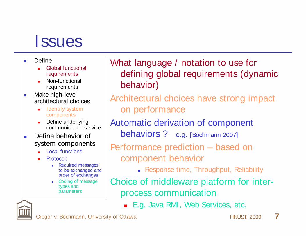
Issues Define
Global functional requirements
Non-functional requirements
Make high-level architectural choices Identify system
components Define underlying
communication service
Define behavior of system components Local functions Protocol:
Required messages to be exchanged and order of exchanges
Coding of message types and parameters
What language / notation to use for defining global requirements (dynamic behavior)
Architectural choices have strong impact on performance
Automatic derivation of component behaviors ? e.g. [Bochmann 2007]
Performance prediction – based on component behavior
Response time, Throughput, Reliability
Choice of middleware platform for inter-process communication E.g. Java RMI, Web Services, etc.

HNUST, 2009 8Gregor v. Bochmann, University of Ottawa
Different system architectures Distributed architectures
Advantages: concurrency, failure resilience, scalability
Difficulties: communication delays, coordination difficulties
Distribution-concurrency at different levels: Several organizations Different types of computers (e.g. servers, desk-
tops, hand-held devices, etc.) Several CPUs in multi-core computers

HNUST, 2009 9Gregor v. Bochmann, University of Ottawa
Proposed notations for global requirements
UML Sequence diagrams UML Activity Diagrams XPDL (workflow) - BPMN (business process) Use Case Maps BPEL (Web Services) – Note: defines centralized behavior
WS-CDL (“choreography”) Collaborations (as proposed by joint work with
university of Trondheim, Norway – see later)
Question: How do they fit with the above
issues ?

HNUST, 2009 10Gregor v. Bochmann, University of Ottawa
Overview of this talk1. Introduction2. Formalisms for describing global
dynamic behaviors3. Deriving component behaviors
3.1 Distributed workflows3.2 Strong sequencing between sub-collaborations3.3 Weak sequencing between sub-collaborations 3.4 Summary
4. Conclusions

HNUST, 2009 11Gregor v. Bochmann, University of Ottawa
2. Describing functional requirements
The functional requirements are usually defined through a number of use cases.
Use cases may be complex and need to be defined precisely.
We consider the following notations for this purpose For structural aspects: Collaboration diagrams For the dynamic behavior:
Activity diagrams (formalization: Petri nets) Sequence diagrams (only for simple cases)

HNUST, 2009 12Gregor v. Bochmann, University of Ottawa
Example of an Activity Diagram

HNUST, 2009 13Gregor v. Bochmann, University of Ottawa
Concepts Each Use Case is a scenario
Actions (Activities) done by actors in some given order Actor: Swimlane - we call it component or role Order of execution:
sequence, alternatives, concurrency, arbitrary control flows (can be modeled by Petri nets)
Interruption through priority events (not modeled by Petri nets)
Abstraction: refinement of activity Data-Flow: Object flow - Question: what type of data is
exchanged (an extension of control flow) Input assertions for input data flow Output assertions for output data flow Conditions for alternatives

HNUST, 2009 14Gregor v. Bochmann, University of Ottawa
Other similar notations The following notations have very similar
semantics: Activity Diagrams (UML version 2) Use Case Maps (standardized by ITU) XPDL / BPMN (for workflow / business process
modeling) BPEL (for Web Services)
Our new approach: An activity may be distributed, we also call it a collaboration
Formalization: Petri nets [Petri 1960]
HNUST, 2009 15Gregor v. Bochmann, University of Ottawa
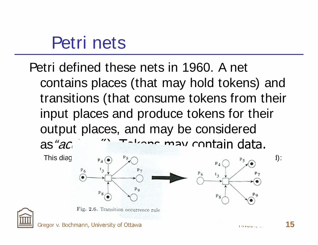
Petri netsPetri defined these nets in 1960. A net
contains places (that may hold tokens) and transitions (that consume tokens from their input places and produce tokens for their output places, and may be considered as“actions” ). Tokens may contain data.This diagram shows what happens when one transition is executed (fired):

HNUST, 2009 16Gregor v. Bochmann, University of Ottawa
Petri net and token machine
Different transitions may execute concurrently. This leads to a large number of possible interleavings (execution orders).
A Petri net is a more condensed representation of all possibilities than a corresponding state machine model (on the right), also called “token machine”.
The token machine is infinite if the number of tokens in some place is not bounded.

HNUST, 2009 17Gregor v. Bochmann, University of Ottawa
Activity Diagram: the corresponding Petri net

HNUST, 2009 18Gregor v. Bochmann, University of Ottawa
Free-choice nets – local choiceno choice
non-free choice
free choice
Component A
Component A
Component B
local choice
Non-localchoice
with conflict place

HNUST, 2009 19Gregor v. Bochmann, University of Ottawa
C
B
Example of a collaboration
sub-collab. SA sub-collab. SB
A A
A
A AB
B C
C
A collaboration is an activity that involves several parties, called roles.
The following example is a collaboration involving three roles A, B and C. Each transition of the Petri net is performed by one of these roles. The order of execution is defined by the Petri net.
BB

HNUST, 2009 20Gregor v. Bochmann, University of Ottawa
Abstract view
Here the internals of the Collaboration SA are hidden. Only places that must contain tokens for starting the execution of the collaboration are shown on the left interface, and places for resulting output tokens are shown on the right interface.
sub-collab. SA
A AB
B
Csub-collab. SA
A
B
B

HNUST, 2009 21Gregor v. Bochmann, University of Ottawa
Composition and abstraction in Petri nets
Composition by joining places
Simplification by introducing abstracted “transitions”
(we will call them “collaborations”).

HNUST, 2009 22Gregor v. Bochmann, University of Ottawa
A “collaboration” is not a transitionThe semantics of an abstracted
transition (a collaboration) is not the same as a transition:
A collaboration may begin some partial execution when some of the inputs are present.
A transition can fire (begin execution) only when all inputs are present.
Note: In UML Activity Diagrams, an activity has this transition property.
When we use Activity Diagrams for modeling collaborations, we assume that an activity is a “collaboration” in the sense above.

HNUST, 2009 23Gregor v. Bochmann, University of Ottawa
Sequence diagrams Sequence diagram (or Message Sequence
Chart - MSC) is a well-known modeling paradigm showing a scenario of messages exchanged between a certain number of system components in some given order.
Limitation: Normally, only a few of all the possible scenarios are shown.
High-Level MSC can be used to describe the composition of MSCs (with weak sequencing – see below)

HNUST, 2009 24Gregor v. Bochmann, University of Ottawa
Example: Taxi system (an activity diagram - each activity is a collaboration between several roles: client, taxi, manager)
new client C
Request Free
Assign
Meet
Pick-up
Drive
Pay
FreeWithdraw
new taxi Ttaxi leaves
client leaves
client leaves
T
T
T
TTT T
T
T
C
C
C C
M
C
M
M
M
M
M
M : taxi manager
initiating role
terminating roles
Off-duty
HNUST, 2009 25Gregor v. Bochmann, University of Ottawa
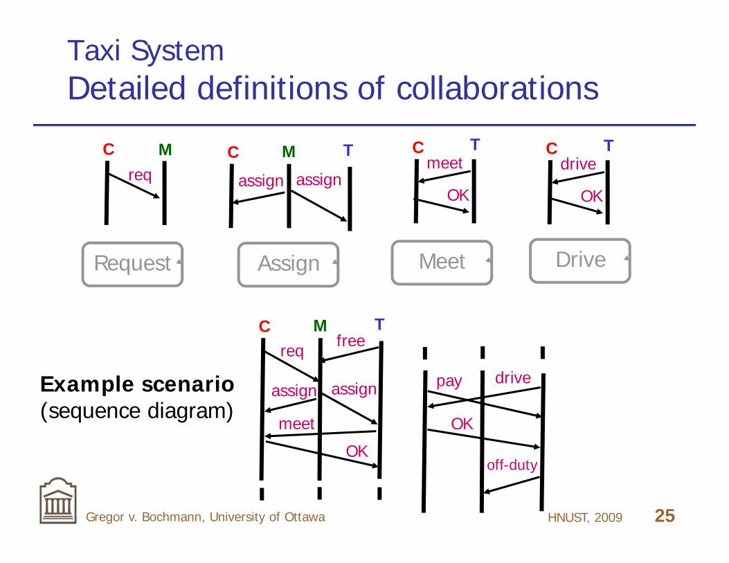
Taxi SystemDetailed definitions of collaborations
reqC M
Request
meet
Drive
OK
CM
Meet
Tdrive
OK
C T
assign
C
Assign
T
assign
M
assign
C T
assign
req free
meet
OK
drivepay
OK
off-duty
Example scenario(sequence diagram)

HNUST, 2009 26Gregor v. Bochmann, University of Ottawa
Taxi System : Problematic scenarios
M
assign
C T
assign
reqfree
non-localchoice
[Gouda 84] suggests: define different priorities
for different roles
M
assign
C T
assign
req free
meetwith-draw
racecondition
M
assign
C1 T
assign
reqfree
C2
pick-up
non-localChoice
(conflict over taxi)“implied scenario”:
[Alur 2000] component behaviors that realize the normal scenario
will also give rise to implied scenarios
HNUST, 2009 27Gregor v. Bochmann, University of Ottawa
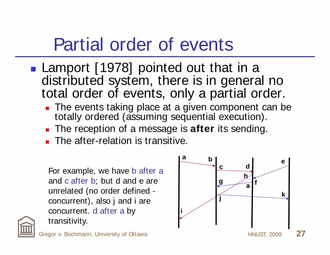
Partial order of events Lamport [1978] pointed out that in a
distributed system, there is in general no total order of events, only a partial order. The events taking place at a given component can be
totally ordered (assuming sequential execution). The reception of a message is after its sending. The after-relation is transitive.
a bc
j
a
e
f
d
i
k
hg
For example, we have b after aand c after b; but d and e are unrelated (no order defined -concurrent), also j and i are concurrent. d after a by transitivity.

HNUST, 2009 28Gregor v. Bochmann, University of Ottawa
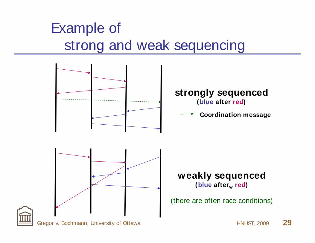
Weak sequencingWeak sequencing (introduced for the High-
Level MSCs) is based on this partial order. Normal (strong) sequencing: C1 ; C2
all actions of C1 must be completed before any action of C2 may start.
Weak sequencing: C1 ;w C2 for each component c, all actions of C1 at c must be
completed before any action of C2 at c may start.(only local sequencing is enforced by each component, no
global sequencing – this often leads to race conditions)
HNUST, 2009 29Gregor v. Bochmann, University of Ottawa
Example of strong and weak sequencing
strongly sequenced(blue after red)
weakly sequenced(blue afterw red)
(there are often race conditions)
Coordination message

HNUST, 2009 30Gregor v. Bochmann, University of Ottawa
Notations for collaborationsUML proposes several notations to describe
different aspects of a system.[Castejon 2010] proposes the following UML
notations (with slight modifications) for the description of collaborations: Collaboration diagram to show the sub-collaborations
and the parties involved (structural aspects) Activity diagram to show the execution order of sub-
collaborations (with extensions to show the initiating and terminating parties)
Sequence diagram to show (for a sub-collaboration) the details of message exchanges

HNUST, 2009 31Gregor v. Bochmann, University of Ottawa
Example: tele-consultationHere is an example of a tele-consultation involving a patient
terminal (pt), doctor terminal (dt) and a testing device (dl) at the patient’s premises.
DataLogger DocTrmPatTrm
doTest
logValues
query
report
loop
ack
discalt
ack
ack
disc
sd Test ow CallDisconnect
LogV
alue
s D
oTes
tG
etV
alue
s
Cal
lDis
conn
ect
Test
Collaborationdiagram
Activitydiagram
SequenceDiagram
(CallSetup not shown)

HNUST, 2009 32Gregor v. Bochmann, University of Ottawa
3. Deriving component behaviors
Do you remember the problem ?

HNUST, 2009 33Gregor v. Bochmann, University of Ottawa
The problem (early phase of the software development process)
Define Global functional requirements Non-functional requirements
Make high-level architectural choices Identify system components Define underlying communication service
Define behavior of system components: Locally performed functions Communication protocol
Required messages to be exchanged and order of exchanges
Coding of message types and parameters

HNUST, 2009 34Gregor v. Bochmann, University of Ottawa
3.1 Distributed workflows We consider here the following situation:
The global dynamic behavior is defined by an Activity diagram (or a similar notation) where each activity either represent a local action at a single component or a collaboration among several components.
Explicit flow relations define a partial order between terminating actions of some activities and initiating actions of other activities.
No weak sequencing is explicitely specified.

HNUST, 2009 35Gregor v. Bochmann, University of Ottawa
An example collaborationPetri nets are a more simple formalism than Activity Diagrams. Therefore it is useful to first look for a general algorithm to derive component behaviors from global behavior specifications in the form of a Petri net. We saw this example earlier.
sub-collab. SA sub-collab. SB
A A
A
A AB
B
B C
C
CBB
HNUST, 2009 36Gregor v. Bochmann, University of Ottawa
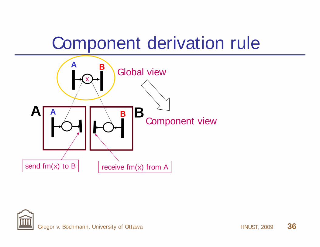
Component derivation ruleA B Global view
Component viewA B
send fm(x) to B receive fm(x) from A
x
A B
HNUST, 2009 37Gregor v. Bochmann, University of Ottawa
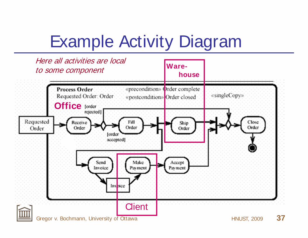
Example Activity DiagramWare-
house
Client
Office
Here all activities are local to some component

HNUST, 2009 38Gregor v. Bochmann, University of Ottawa
Office component
OfficeSend
to wareh.
Receive from
wareh.
to Client
Payment
from Client
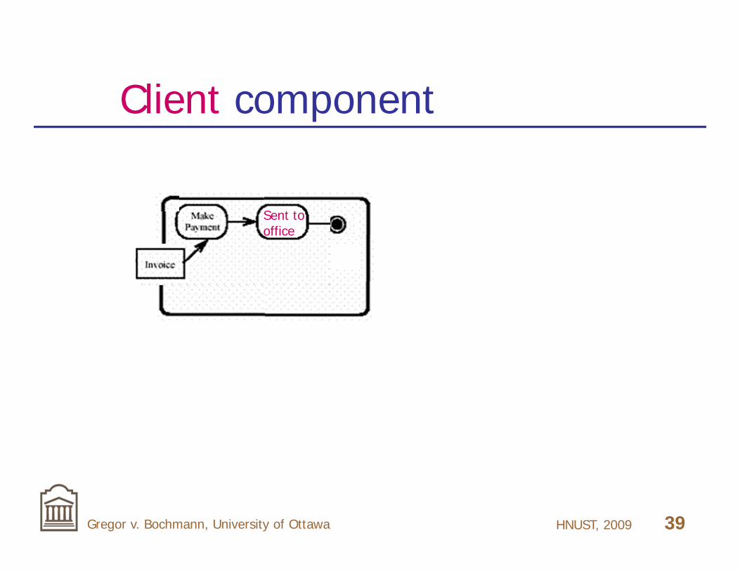
If a partial order relation goes from one component to another, then it should give rise to a send and receive operation in the respective components.
HNUST, 2009 39Gregor v. Bochmann, University of Ottawa
Client component
Sent tooffice

HNUST, 2009 40Gregor v. Bochmann, University of Ottawa
3.2. Strong sequencingbetween abstract sub-collaborations
Collab. SA Collab. SBs
This strong sequence means: all actions of SA must be completed before actions of SB can start.
The diagram below does not give strong sequencing: e.g. the transition of C of collaboration SA may occur after or during collaboration SB.
sub-collab. SA sub-collab. SB
A
A
A AB
B
B C
C
BB

HNUST, 2009 41Gregor v. Bochmann, University of Ottawa
Initiating and terminating actions
initiating action - no action is earlier (according to the partial order)
terminating actions - no action is later Strong sequencing SA ;s SB can be enforced
by ensuring that all terminating actions of SA occur before all initiating actions of SB.
Transition C in SA is a terminating action.
Only after a, b and c have a token should tokens arrive in d and e.
sub-collab. SA sub-collab. SB
A
A
A AB
B
B CC
BB
a
b
c
d
e

HNUST, 2009 42Gregor v. Bochmann, University of Ottawa
Realizing strong sequence
Collab. SA
A
B
C
Collab. SB
A
B B
located at some given component
centralizedrealization
Collab. SA
A
B
C
Collab. SB
A
B B
Distributed Realization (first described in [Bochmann 86])
then apply derivation rule
A
B
B
A
C
Two ways to coordinate the terminating and initiating actions: centralizedand distributed
B
B

HNUST, 2009 43Gregor v. Bochmann, University of Ottawa
Choice propagation
Collab. SC
A
AA B
B
C
Component B should know which alternative was chosen (include parameter xi in flow message)
x1
x2
Here the choice is done by component A (local choice)

HNUST, 2009 44Gregor v. Bochmann, University of Ottawa
3.3. Component design for weak sequencing
We have described an algorithm for deriving component designs from global behavior specifications – including weak sequencing [Bochmann 2007]
It uses the approach described above and includes the following features for dealing with weak sequencing: Selective consumption of received messages
Received message enter a pool. The component fetches (or waits for) a given message when it is ready to consume it (like the Petri net models, see also [Mooij 2005])
An additional type of message: choice indication message
Additional message parameters, e.g. loop counters

HNUST, 2009 45Gregor v. Bochmann, University of Ottawa
Need for choice indication message (cim)
With weak sequencing, each component must know when the current sub-collaboration is locally complete in order to be ready to participate (or initiate) the next sub-collaboration.• This is difficult for component C at the end of sub-collaboration B (above) if the upper branch was chosen (no message received).
Therefore we propose a choice indication message( from A to C in this case )
A
B
sub-collab. SA sub-collab. SB
A
A
AB
B CC
BB
a
b
c
d
e
C
;w
;w

HNUST, 2009 46Gregor v. Bochmann, University of Ottawa
Need for loop countersWith weak sequencing, a message referring to the
termination of a loop may arrive before a message referring to the last loop execution. See example:
R1 R2 R3
b(u2)
a(u1)
a(u2)b(u1)
c(v2)
R1a
R2 R3
b
UR1 R2 R3
V
cd
e f
Note: Nakata [1998] proposed to include in each coordination messagean abbreviation of the complete execution history.

HNUST, 2009 47Gregor v. Bochmann, University of Ottawa
3.4 Summary1. Define requirements in the
form of a collaboration model2. Architectural choices: allocate
collaboration roles to different system components
3. Derive component behavior specifications (automated)
4. Evaluate performance and other non-functional requirements (revise architectural choices, if necessary)
5. Use automated tools to derive implementations of component behaviors.
Service2
Service1
Service3
C 1 C 2 C 3 C 4
S1.1 S1.2
Design synthesis
Code generation
Service2
Service1
Service3
C 1 C 2 C 3 C 4
S1.1 S1.2
Design synthesis
Code generation

HNUST, 2009 48Gregor v. Bochmann, University of Ottawa
Algorithm for deriving component behaviors
Step 1: Calculate starting, terminating and participating roles for each sub-collaboration
Step 2: Use architectural choices to determine starting, terminating and participating components.
Step 3: For each component, use a recursively defined transformation functionto derive the behavior of the component from the global requirements (principles explained above, for details see [Bochmann 2007])

HNUST, 2009 49Gregor v. Bochmann, University of Ottawa
Historical comments Initially, only strong sequencing, choice and
concurrency operators, plus sub-behaviors [Bochmann and Gotzhein, 1986 and Gotzhein and Bochmann 1990]
Main conclusions: Strong sequencing requires flow messages; need to identify
initiating and terminating roles Choice propagation: need for unique message parameters
More powerful languages LOTOS [Kant 1996]
recursive process call: >> ; disruption operator: [> (impossibility of distributed implementation)
Language with recursion and concurrency [Nakata 1998]

HNUST, 2009 50Gregor v. Bochmann, University of Ottawa
… for Petri nets
Restriction: free-choice PN and “local choice”(as discussed above) [Kahlouche et al. 1996]
general Petri nets [Yamaguchi et al. 2007]
It is quite complex (distributed choice of transition to be executed, depending on tokens in places associated with different sites)
Note: These methods can be easily extended to Colored Petri nets (or Predicate Transition nets): exchanged messages now contain tokens with data parameters
Petri nets with registers (see next slide) [Yamaguchi et al. 2003]

HNUST, 2009 51Gregor v. Bochmann, University of Ottawa
… for Petri net with registersThe Petri net has Local registers (e.g. R, R’)
A transition has External input or output
interaction (e.g. G) Enabling predicate Update operations on
registers
• The component behavior includes messages to exchange register values for evaluating predicates and updating registers. • The number of required messages depends strongly on the distribution of the registers over the different components. –Optimization problem.

HNUST, 2009 52Gregor v. Bochmann, University of Ottawa
Remaining problems Support complex temporal order relationships
with weak sequencing Example:
Data flow from non-terminating components
Concurrent sessions and dynamic selection of collaboration partners
Proof of correctness of derivation algorithm
HNUST, 2009 53Gregor v. Bochmann, University of Ottawa
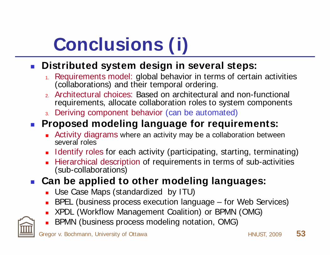
Conclusions (i) Distributed system design in several steps:
1. Requirements model: global behavior in terms of certain activities (collaborations) and their temporal ordering.
2. Architectural choices: Based on architectural and non-functional requirements, allocate collaboration roles to system components
3. Deriving component behavior (can be automated) Proposed modeling language for requirements:
Activity diagrams where an activity may be a collaboration between several roles
Identify roles for each activity (participating, starting, terminating) Hierarchical description of requirements in terms of sub-activities
(sub-collaborations) Can be applied to other modeling languages:
Use Case Maps (standardized by ITU) BPEL (business process execution language – for Web Services) XPDL (Workflow Management Coalition) or BPMN (OMG) BPMN (business process modeling notation, OMG)

HNUST, 2009 54Gregor v. Bochmann, University of Ottawa
Conclusions (ii)
Many fields of application: service composition for communication services workflows e-commerce applications - Web Services Grid and Cloud computing Multi-core computer architectures
Further work: proving correctness of derivation algorithm tools for deriving component behavior specifications performance modeling for composed collaborations “agile dynamic architectures”

HNUST, 2009 55Gregor v. Bochmann, University of Ottawa
References [Alur 2000] Alur, Rajeev, Etessami, Kousha, & Yannakakis, Mihalis. 2000. Inference of message sequence charts.
Pages 304–313 of: 22nd International Conference on Software Engineering (ICSE’00). [Boch 86g] G. v. Bochmann and R. Gotzhein, Deriving protocol specifications from service specifications, Proc. ACM
SIGCOMM Symposium, 1986, pp. 148-156. [Bochmann 2008] G. v. Bochmann, Deriving component designs from global requirements, Proc. Intern. Workshop on
Model Based Architecting and Construction of Embedded Systems (ACES), Toulouse, Sept. 2008. [Castejon 2007] H. Castejón, R. Bræk, G.v. Bochmann, Realizability of Collaboration-based Service Specifications,
Proceedings of the 14th Asia-Pacific Soft. Eng. Conf. (APSEC'07), IEEE Computer Society Press, pp. 73-80, 2007. [Castejon 2010] H. Castejón , G.v. Bochmann, R. Bræk, Using Collaborations in the Development of Distributed
Services, submitted for publication. [Gotz 90a] R. Gotzhein and G. v. Bochmann, Deriving protocol specifications from service specifications including
parameters, ACM Transactions on Computer Systems, Vol.8, No.4, 1990, pp.255-283. [Goud 84] M. G. Gouda and Y.-T. Yu, Synthesis of communicating Finite State Machines with guaranteed progress,
IEEE Trans on Communications, vol. Com-32, No. 7, July 1984, pp. 779-788. [Lamport 1978] L. Lamport, "Time, clocks and the ordering of events in a distributed system", Comm. ACM, 21, 7, July,
1978, pp. 558-565. [Kant 96a] C. Kant, T. Higashino and G. v. Bochmann, Deriving protocol specifications from service specifications
written in LOTOS, Distributed Computing, Vol. 10, No. 1, 1996, pp.29-47. [Mouij 2005] A. J. Mooij, N. Goga and J. Romijn, "Non-local choice and beyond: Intricacies of MSC choice nodes", Proc.
Intl. Conf. on Fundamental Approaches to Soft. Eng. (FASE'05), LNCS, 3442, Springer, 2005. [Nakata 98] A. Nakata, T. Higashino and K. Taniguchi, "Protocol synthesis from context-free processes using event
structures", Proc. 5th Intl. Conf. on Real-Time Computing Systems and Applications (RTCSA'98), Hiroshima, Japan, IEEE Comp. Soc. Press, 1998, pp.173-180.
[Sanders 05] R. T. Sanders, R. Bræk, G. v. Bochmann and D. Amyot, "Service discovery and component reuse with semantic interfaces", Proc. 12th Intl. SDL Forum, Grimstad, Norway, LNCS, vol. 3530, Springer, 2005.
[Yama 03a] H. Yamaguchi, K. El-Fakih, G. v. Bochmann and T. Higashino, Protocol synthesis and re-synthesis with optimal allocation of resources based on extended Petri nets., Distributed Computing, Vol. 16, 1 (March 2003), pp. 21-36.
[Yama 07] H. Yamaguchi, K. El-Fakih, G. v. Bochmann and T. Higashino, Deriving protocol specifications from service specifications written as Predicate/Transition-Nets, Computer Networks, 2007, vol. 51, no1, pp. 258-284
HNUST, 2009 56Gregor v. Bochmann, University of Ottawa
Thanks !
Any questions ??
For copy of slides, see
http://www.site.uottawa.ca/~bochmann/talks/Deriving-3.ppt