derek piggott - amazon s3...illustrations 1 difference between gliders and sailplanes 2 developments...
TRANSCRIPT

DEREK PIGGOTT
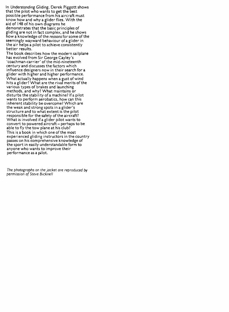
In Understanding Gliding, Derek Piggott shows that the pilot who wants to get the best possible performance from his aircraft must know how and why a glider flies. With the aid of 148 of his own diagrams he demonstrates that the basic principles of gliding are not in fact complex, and he shows how a knowledge of the reasons for so me of the seemingly wayward behaviour of a glider in the air helps a pilot to achieve consistently better results.The book describes how the modern sailplane has evolved from Sir George Cay ley's 'coachman-carrier' of the mid-nineteenth century and discusses the factors which influence designers now in their search for a glider with higher and higher performance. What actually happens when a gust of wind hits a glider? What are the rival merits of the various types of brakes and launching methods, and why? What maintains or disturbs the stability of a machine? If a pilot wants to perform aerobatics, how can this inherent stability be overcome? Which are the weak and strong spots in a glider's structure and to what extent is the pilot responsible for the safety of the aircraft? What is involved if a glider pilot wants to convert to powered aircraft - perhaps to be able to fly the tow plane at his club? This is a book in which one of the most experienced gliding instructors in the country passes on his comprehensive knowledge of the sport in easily understandable form to anyone who wants to improve their performance as a pjlot.
The photographs on the jacket are reproduced by permission of Steve Bicknell

Understanding Gliding

By the same author
Gliding: A Handbook on Soaring FlightBeginning Gliding: The Fundamentals of Soaring Flight

UnderstandingGliding
The Principles of Soaring Flight
Derek PiggottWith illustrations by the author
ADAM AND CHARLES BLACK • LONDON

First published 1977Reprinted 1979A & C Black (Publishers) Limited35 Bedford Row, London WCiR 4JH
ISBN o 7136 1640 7
© Derek Piggott 1977
All rights reserved. No part of this publication may be reproduced, stored in a retrieval system, or trans mitted, in any form or by any means, electronic, mechanical, photocopying, recording or otherwise, without the prior permission of A & C Black Limited
Printed and bound in Great Britain by Morrison and Gibb Ltd., London and Edinburgh

Contents
List of illustrations 6
Introduction 9
1 The evolution of the modern sailplane 112 How and why a glider flies 223 The effect of the wind 704 Design for performance 1065 Airbrakes and other drag producing devices 1246 Launching methods 1337 Fore and aft stability and control 1458 Lateral stability and control 1759 Directional and spiral stability and control 186
10 Flight limitations 19511 Glider structures 21012 Converting from gliders to powered aircraft 218
AppendixesA The Yates effect 238B A suggested syllabus for training a Silver *C' glider pilot to
Private Pilots' Licence standard 240C Vectors and force diagrams simply explained 242D Conversion tables 251
Index 253

Illustrations
1 Difference between gliders and sailplanes
2 Developments 1800-19273 Developments 1935-19734 Comparison of bicycle and glider5 How gliders gain height6 Gravity and climbing gliders7 Flat plates to aerofoils8 Bernoulli's theorem9 Flying attitude and angles of
attack10 Angles of incidence and attack11 The stall12 Balance of forces in flight13 Gliding angles and the lift/drag
ratio14 Attitude and the gliding angle15 Stick position and angle of attack16 Landing17 Lift and angle of attack18 Loading in manoeuvres19 Forces in a turn20 Adverse yaw effect21 Effect of wing span22 A.S.I, errors23 Aileron movements at the stall24 Spinning off turns25 Circular flow effects in turns26 Stalling speeds in turns27 Speed margins in turns28 Control moves for a turn29 Incipient and full spins30 Lateral damping31 Autorotation32 Excess rudder at low speeds
12
141523
24
25
27
28
3i323334
36373940
434446464748495i5253545758596i
3334353637383940414243444546474849
50
525354555657585960616263646566
Special glider characteristics 62Rudder blanketing in spins 65 Effect of C of G position on spins 67
36 Normal and inverted spins 68Stalling in loops 69The wind sock 71Weather map 72Variation in wind with height 73Veering and backing 73Wind shear and landings 74Buys Ballots law 75Gradient winds 75Blocks of air 76
46 Effect of wind on gliding angle 78Kiting on the launch 79
48 Circling in a strong wind 79 Turning onto the base leg instrong wind 80Drifting across the wind 81Squalls 82Wind gradient 83Effect of wind gradient 84The 'clutching hand' effect 85Lee waves and turbulent flow 88
56 Exchanging height for speed 90The result of the Yates effect 91Formation of thermal bubbles 92Using rotating thermals 93Cross-section of thermal bubble 94Flying through thermals 95Inflow and outflow in a thermal 96
63 Circling near a hill 97Low turns into and downwind 99
65 Double gradient effect 101Dynamic soaring 103

67 Model aircraft in still air and in wind
68 Polar curve69 Aspect ratio70 Induced drag71 Wing shapes72 Effects of washout73 Wingtip shapes74 Form drag75 Laminar and turbulent flow76 Types of aerofoil77 Need for clean wing surfaces78 Induced, form and total drag79 Airbrakes and geometric lock80 Types of airbrakes and flaps81 Comparison between airbrakes
and flaps82 Tail parachutes83 Sideslipping84 Winching and car launching85 Effect of hook position86 Important facts about launching87 Extra stresses during launching88 The release hook and safety
devices89 Longitudinal stability90 Forces on an aerofoil91 Lift and drag forces92 Centre of pressure movements93 Flying wing gliders94 Action of the stabiliser95 Trimming devices96 Stick fixed stability97 Instability98 Tail loads at high speeds99 All-moving stabilisers
100 Spring trimming101 Types of tail102 Vee tails103 Horn balances104 Mass balances105 Pilot induced oscillations106 Stopping phugoid oscillations107 How to trim
105 108 no inH3 114
116117118121
122
125
126
128
130
131
134
137139
141
143
146
146
147148
149
150
153
1 56
1571 5 8
1 60
161162163165166167169170
108 Trimming in turns 172109 Sideslipping in turns 176no Dihedral and sweepback 177in Sweepback and anhedral 179112 Aileron reversal 180113 Reducing aileron drag 182114 Aileron flutter 184115 Directional stability 187116 Sideslipping characteristics 187117 Directional control when wheel
is ahead of C of G 189118 Directional control when wheel
is behind C of G 190119 Spiral stability 191120 Cockpit placards 196121 Typical flight envelope 198122 Looping 202123 Wing loads with airbrakes 203124 Stall turns and chandelles 204125 Tailslides 205126 Rolling 207127 Inverted flying 208128 Wing structures and bending
loads 2ii129 Torsional loads 212130 Looking for damage 215131 Effects of changing power 221132 Take off 223133 Slipstream effect 224134 Offset blade effect 225135 Gyroscopic effect 226136 Torque 226137 Nose and tail wheel aircraft 228138 Effect of drag curve 229139 Typical power circuit 231140 The Yates effect 239141 Forces in equilibrium 243142 Resultant of two forces 243143 Vector diagrams 244144 Balance of forces in flight 245145 Straight and level flight 246146 Forces in turns 247147 Measuring track angle 248148 Triangle of velocities 249

Introduction
There are very few mysteries left in flying and yet the majority of glider -«, pilots do not really understand why an aircraft behaves as it does. The fundamental principles are easy to grasp and should not involve complicated mathematical and algebraic formulae. In this book I have tried to write about gliding and soaring in a really practical manner and to explain most of the mysteries.
As I said in Beginning Gliding) both 'glider' and 'sailplane* are correct terms to describe soaring aircraft and it is unimportant which we choose to use. In Britain we speak of flying gliders and of gliding, whereas in the USA, and a few other countries, the same aircraft are always known as sailplanes.
Some readers may not be familiar with the use of knots (nautical miles per hour) as a unit of speed in connection with flying. A knot is almost exactly 100 feet per minute and this makes it particularly useful for glider flying where the pilot may want to estimate his gliding angle quickly. For example, a rate of descent of 2 knots at a speed of 60 knots indicates a gliding angle of 1130 in no wind. The same calculation with the variometer calibrated in feet or metres a second and speeds of miles or kilometres per hour requires a mental calculation involving multiplying by 60 twice, and this is not practical for the average pilot in flight.
It seems probable that, in spite of the move towards metrication, dis criminating glider pilots will continue to use knots and nautical miles for measurement, at least in countries where heights are referred to in hundreds and thousands of feet. The nautical mile has the added advantage of being one minute of latitude and this enables a pilot to measure or estimate distances on any map or chart by referring to the distance between lines of latitude, instead of having to find the scale - which may be inaccessible at the time.
Conversion tables are given in Appendix D.Learning to glide and understanding about gliding are the foundations of
soaring flight.

The evolution of the modern sailplane
Before considering how and why a glider flies, it is interesting to trace the evolution of the design and construction of sailplanes up to the present day. The growing enthusiasm for preserving and renovating gliders of historic interest means that many people will actually be able to see examples of early designs both in museums and being flown regularly at gliding sites.
The first successful man-carrying gliders were almost certainly those designed and built by Sir George Cayley, an Englishman, who lived near Scarborough from 1773-1857.
Recent research into his work and the reconstruction and flights of a near replica of one of his man-carriers, have confirmed that Sir George Cayley was the father of the practical aeroplane as we know it today. He understood streamlining and the need for a cambered aerofoil for efficient lifting power. If his discoveries and experiments had been followed up by other enthusiasts, practical flying machines would probably have been in the air almost fifty years earlier.
By 1804 he had evolved the modern conventional layout, with a stabilising tailplane and fin mounted behind the wing, as a result of his experiments with model-size gliders. Although he did not use any lateral control such as wing warping or ailerons, many of his machines used dihedral and had the wings mounted high above the centre of gravity in order to provide extra lateral stability. Encouraged by the success of his smaller models he built very large machines and tested them with ballast before attempting flights, first with animals and finally with human passengers. History recounts how his coachman resigned after being flown across the valley at Brompton Dale in 1853. At the time Sir George was 80, and therefore unable to fly himself.
After Cayley's death there was little progress in the design of heavier than air machines until 1891 when Otto Lilienthal built and flew a number of hang gliders in Germany. Similar types of glider were flown by Percy Pilcher and other pioneers, but since the only means of controlling them was by the pilot shifting his weight, their success was rather limited and there were several fatal accidents.
At about the same time, Orville and Wilbur Wright started their experi ments with gliders in the USA, but, unlike their predecessors, they relied upon proper controls rather than built-in stability. This involved them in the problems of learning to fly but gave them enough control to correct the effects of gusts of wind and to make turns. They made many soaring flights using the upcurrent created by the wind blowing over a ridge of hills, including one very notable flight of nine and three-quarter minutes. However, gliding was for
11

1 All motorless aircraft are gliders. Sailplanes are gliders designed for soaring flight. Gliders
Hamilcar Tank Carrier
Sailplanes
them a means of teaching themselves how to fly and as soon as they had developed a suitable engine, they concentrated on the problem of producing a practical powered machine.
The possibility of making long, soaring flights with gliders was more or less forgotten until after the First World War. Then many German pilots and flying enthusiasts realised that gliding was a way of flying which they could afford and which had not been specifically denied to them by the terms of the Versailles treaty. As a result, within a few years glider flights were being measured in hours instead of minutes and the sport of soaring was established in many countries.
Whereas the First World War had resulted in rapid advances in aircraft design, it was the spirit of friendly competition and, in particular, the enthusiasm inspired by the international gliding competitions held in Germany in the 19208 and 19308 which were responsible for the development of the high performance sailplane.
The effect of the wind blowing over a ridge of hills was well understood by this time and with an adequate wind strength in the right direction, hill soaring was possible with comparatively low-performance gliders. The strength of the hill lift depends mainly on the wind speed and the average angle of the slope, and even a moderate wind of 20 knots blowing up a slope of 113 will produce an upcurrent of about 600 feet per minute.
12

It is not difficult, therefore, to produce a satisfactory hill soaring machine for use in strong wind conditions. Since the rate of sink is proportional to both the gliding angle and the flying speed, an acceptably low sink rate may be obtained just by making the glider fly slowly, even if the gliding angle is relatively poor. A low flying speed is largely a matter of building a very light machine with a large wing area; i.e. having a low wing loading. The weight of the wing structure can be kept very low if it is wire or strut braced. This would have a serious drag penalty at high speed but for normal hill soaring at low speed the extra drag is not sufficient to affect the soaring performance significantly.
The modern Rogallo type of sailwing hang glider is an extreme example of a large wing area and low weight. The gliding angle is only about 5:1 but, with its low flying speed of about 20 knots, it can be soared quite successfully in strong winds if the slope of the hill is steep. However, unless you happen to live in an area with good hills and strong winds, flying this kind of machine will not be very rewarding.
The pioneers of the 19208 found this out for themselves and soon realised the need to obtain much lower rates of sink in order to be able to soar in light winds. It was still important to keep the wing loading and flying speed low, but an improvement in the gliding angle was even more valuable. This could only come from an increase in efficiency - that is by improving the lift and reducing the drag.
Up to this stage of development most of the gliders relied on two mainspars in the wing to take both the bending loads and the twisting forces which act on a wing in flight. Struts or wires were used to stop the twisting tendency and they also greatly reduced the strength and weight of the spars necessary for a strong, stiff wing. Gliders were becoming much more streamlined and soon the drag of the struts represented a significant amount of the total drag of the whole machine and could no longer be tolerated. Doing away with the struts and using a cantilever wing required a much stronger and heavier main spar and it also presented new problems in keeping the wing sufficiently stiff. Torsional stiffness is of vital importance because there is a very distinc tive tendency for a wing to twist at high speeds and when the ailerons are used. If this happens the ailerons become ineffective, or produce the opposite effect, and the twisting may even result in structural failure.
The solution to this problem was to adopt the D, or torsion box leading edge to the wing. With this design the main spar takes the bending and shear loads and the torsion box prevents the wing from twisting. In addition, the thin plywood skin used for the torsion box greatly improves the shape and surface of the leading edge and enhances the performance. Not only the rate of sink at low speeds but also the gliding angle at a higher speed were much improved, so that the glider could make more headway against stronger winds. This meant that it could make better progress from one hill to another and so fly across country.
It was at about this stage of development that glider pilots began to notice
13

1808 Cayley's kite-type model glider
1853 The coachman carrier (replica 1973)
1850 Cayley's model glider
Sir George Cayley, 1773-1857The true inventor of the aeroplane
1890-1898 Otto Lilienthal andPercy Pilcher hang gliders
1920 Schwarze Teufll
1900-1911 The Wright Brothers' glider
1927 Darmstadt D H 1922 Vampyr
2 The evolution of the modern sailplane 1800-1927.
14

1930-1950 SG 38 Primary glider
1938 DPS Meise (Olympia)
1935 Grunau Baby
1938 DPS Reiher
1938 Horten Tail-less
1972 Rogallo hang glider
1973 SB 10
1960 SZD Foka
3 Sailplane development from 1935-1973.
15

that whenever shower clouds drifted over their hill sites the lift improved and they were able to climb to much greater heights. Soon the pilots were deliber ately leaving their hill lift to explore the area under the clouds for this new kind of lift. The glider pilot had at last become free of his dependence on the hills and the wind. Cross-country flying, as we know it today, had begun.
It did not take long to discover that the most efficient way to climb under and inside these cumulus clouds was to circle like the birds. A simple type of variometer was soon developed to help the pilot find the best areas of lift and within a short time flights of over a hundred miles were not uncommon.
It soon became clear that the so-called cloud lift was really the result of thermals leaving the ground and that these often occurred in spite of there being no actual cloud formation. Whereas with hill soaring the primary aim had been to keep a very low rate of descent, with thermalling it became more important to have a flat gliding angle so that more air could be covered in the search for the next thermal. It also became very important to be able to turn quickly and manoeuvre as accurately as possible in the turbulent air of the thermals.
While the hill lift was limited to a few times the height of the hill, thermals usually went to three or four thousand feet and often gave rates of climb of several hundred feet per minute. The penalty of a slight increase in the rate of sink of the glider became insignificant compared with the bonus of being able to glide a little further in search of a new thermal. It became an advantage to reduce the drag even at the expense of extra weight. The very thick, bulbous aerofoils which had been developed for hill soaring machines were replaced by thinner, more streamlined ones. These perhaps did not produce quite so much lift at low speeds but they had far less drag when the glider was flown with extra speed against the wind or through sinking air between thermals.
As the gliding angles improved, so the problems of landing in a restricted area became much worse and the technique of sideslipping down was inadequate as a means of approaching steeply over tall trees or other obstruc tions. Spoilers and airbrakes were introduced in order to give the pilot an easy way to control the approach and to make a spot landing.
By the outbreak of the Second World War, glider designs were very refined and the best machines had glide ratios of about 1130. An inter national competition for the design of a 15 metre span glider suitable for use in the Olympic games had inspired many fine designs and although these games never took place because of the outbreak of war, the winning design by Hans Jacob, known in Germany as the Meise and elsewhere as the Olympia, was produced all over the world in large numbers. The design set new standards in control and handling, had powerful airbrakes, a good all-round soaring performance, and yet was suitable for even a beginner to fly.
At about the same time, the German Horten brothers were developing their flying wing designs to challenge the conventional machines such as the Weihe (pronounced as in Viaduct) and the Darmstadt 030. In spite of the
16

Horten's very clean design and the elimination of a normal stabiliser and fuselage, the conventional Weihe remained supreme in championship flying.
During the war years, the quest for faster fighters and bombers led to research and the development of the so-called laminar flow aerofoils. Wind tunnel tests in the USA had shown that the NACA 6000 series of aerofoils offered a possible bonus for gliders as well as powered machines. However, the problem of constructing a lightweight glider wing with a good enough surface to obtain this bonus still had to be solved. It was easy with a thick metal skin on a powered machine but quite another problem with the plywood skin of a glider, which is often only one-sixteenth of an inch thick.
In order to maintain the necessary smoothness, the ply skin of the torsion box had to be extended back over most of the wing. The spacing of the sup porting ribs had also to be closed up to prevent the plywood sagging. Most importantly, the contours of the whole wing had to be built to hitherto un- thought of tolerances while keeping the weight as low as possible.
The new low-drag sections were an almost instant success. There was a noticeable improvement in both the best gliding angle and the gliding angles at higher speeds. In addition there was an unexpected advantage in the form of better aileron control. It soon became clear that the reason for having to use large, wide chord ailerons on the earlier designs was that the wings had been twisting under load. The thicker skins needed for the laminar flow wings resulted in a much stiffer wing and allowed the designer to reduce the size of the ailerons considerably.
Soon all but the basic training machines were using laminar flow aerofoils and in the quest for still better performance designers began to look again at the fuselage shape and wing root joints for ways of reducing the drag further.
Up to this time pilots had been sitting more or less normally in an upright position but by redesigning the control runs so that they were either side of the cockpit instead of under the seat, and by making the pilot's position less upright, designers found the frontal area could be reduced. The conventional front skid and main wheel were other sources of drag which had to be elimin ated and this was achieved by moving the wheel forward to ahead of the centre of gravity and by making it retract.
Pilots soon learned to accept the less upright seating position as comfortable and necessary in the interest of lower drag. Before this, good forward visibility had been considered essential and a bulbous canopy shape had been usual. A few designs apeared with the pilot laid out flat in the slimmest possible fuselage, but this extreme soon gave way to the present day compromise of the pilot sitting at an angle of about 45°.
Later, the same principles of maintaining laminar flow over the wing were applied in three dimensional flow over the nose of the fuselage. This involved calculating the pressure gradient over the nose and reshaping it very accur ately. Since any joint or step in the surface would result in turbulent flow, the forward portion of the canopy became fixed so that the joint did not occur until the airflow was past the transition point. Designers also began to pay
17

much more attention to sealing the canopy in order to eliminate any leakage of air which might cause further turbulence. The risk of leakage was also reduced by venting at the tail to reduce the pressure slightly inside the fuselage and cockpit.
Once the airflow in the boundary layer has become turbulent there is less tendency for it to separate and leave the surface than when it is laminar. Many gliders took advantage of this by reducing the cross-section of the fuselage behind the wing and adopting a pod and boom type of fuselage. The drag reduction is the result of a reduction in surface area and there is there fore less skin friction. As with a wing aerofoil, laminar flow cannot be main tained at all speeds and angles of attack on the fuselage nose. The use of variable camber wing flaps helped to extend the range of speeds for main taining extensive laminar flow over both the wing and the nose of the fuselage by reducing the change in angle of attack required for varying the speed. It is possible to make quite a large change in flying speed by raising and lowering the flaps with little or no change in fuselage attitude.
In the USA Doctor Raspet pioneered the development of the modern glider with his work in reducing drag by eliminating surface wavyness and by improving the design of the wing roots and other drag producing areas.
But perhaps the most outstanding contribution to the advancement of glider design has come from Professor Wortman and Doctor Eppler, two German scientists who developed special aerofoils for gliders. These have now superseded the earlier NACA 6000 series and are used on almost all recent designs (1976).
The problem of improving the performance of a modern glider still further can be understood when it is realised that the total drag of a machine weighing 900 Ib flying at about 50 knots is in the order of 20-30 Ib. The performance is therefore drastically reduced by dust and dirt on the wing, or by the failure to seal any joints in the wing root with adhesive tape.
The requirements for the ultimate soaring machine are conflicting ones. In order to use thermals efficiently the glider must have easy handling and good control response so that it can be manoeuvred quickly into the centre of the lift. It must also have a low rate of sink at low speeds in order to use small weak thermals. A low speed gives a small radius of turn and is frequently the key factor which determines whether a particular type of glider can stay up in difficult soaring conditions. However, in cruising flight between areas of lift it needs a flat gliding angle at high speed, and, of course, at the end of the flight it must be easy to land in a confined space.
Good low-speed performance for thermalling is best obtained by having a low wing loading, since the wing loading determines the minimum flying speed, and the radius of turn is proportional to the speed. However, good performance at high speed is easiest to obtain with a high wing loading since this increases the speed for the best gliding angle.
If the lift is strong, the glider with a high wing loading will average a much higher speed, in spite of climbing less efficiently. However, if the lift
18

is very weak it might be unable to climb at all and the extra wing loading is a definite disadvantage. The need for adjustment according to the conditions is to some extent met by carrying jettisonable water ballast in the wings. On a promising looking day when the lift is strong, the wing loading can then be increased by filling up the ballast tanks before take off. If the lift becomes weak and there is a risk that the glider will be unable to stay up, the water can be jettisoned so that the wing loading is reduced again to give the lowest possible sinking speed. Unfortunately, if the weather improves a few minutes later the pilot cannot reverse the process and must make do with his light weight and slower machine for the rest of the flight. The use of water ballast is not new but has become worthwhile owing to the intense competition to achieve the highest possible performance.
The alternative to carrying water ballast is to change the effective wing loading, either by changing the wing area in flight or by altering the aerofoil in order to change the lift coefficient. The wing area may be increased by extending wing flaps for circling flight in the thermals, and reduced again by retracting them for efficient high-speed flight between thermals. However, this is not easy to do without incurring drag losses which more than offset the advantages gained. It is very difficult to design a wing with an extending flap which does not have joints and slots which leak air and create extra drag. In most cases these losses cancel out the advantages, and a simple, clean wing without the complication and weight of flaps is just as efficient. Once the structural problem of making the flaps without the resultant excessive drag losses has been solved, variable geometry like this offers a significant improvement in performance because it allows a much higher wing loading to be used for better performance at high speeds while retaining satisfactory low-speed performance for circling flight and climbing. Unlike water ballast, the two configurations can be used again and again during the same flight.
The use of trailing edge flaps, which vary the camber of the aerofoil, give much the same effect but on a smaller scale. They are easier to construct without large weight or drag penalties. In many machines the ailerons are arranged to raise and droop as the flaps are moved up and down, which has the effect of changing the camber of the wing along the complete span. Unfortunately, when the flaps and ailerons are lowered for low-speed flight, the aileron drag is increased. This spoils the handling of the machine at low speeds and necessitates the use of much more rudder, just at the time when it is important to control the aircraft easily and accurately in order to centre into the strongest lift.
It is difficult to predict what improvements are still possible apart from the development of even better aerofoils. Many of the more recent designs have had some rather poor features which have tended to make them un necessarily difficult to land, or prone to damage on the ground. Apart from these points it is in the structural design that most improvement may be hoped for.
Since the adoption of the laminar flow wing sections, designers have shown
19

great ingenuity in trying out new forms of wing structures in order to produce accurate, smooth surfaces. Some tried stabilising thin plywood skins with numbers of spanwise stringers to eliminate the need for a heavy main spar (SHK and Foka). Others tried using very thick top and bottom plywood skins to form a large box spar and then building fairing shapes onto the leading and trailing edge (Finnish Vasama).
Metal structures are also used in some gliders and have various advantages. However, unless the skins are reasonably thick the surface is scarcely smooth enough to make the best use of the modern aerofoils. A thin skin tends to buckle under load and it is a skilled business to rivet thin skins and smooth out any joints with filler. Stabilising the skin with foam materials and honey combs has also been tried with varying degrees of success (HPio and prototype BGioo).
Perhaps the most striking advance in structural design has been the introduction of glass fibre for primary structure. This was almost entirely due to the wonderful work of the students at various universities and technical institutes in Germany who pioneered the design of glass fibre machines and carried out the testing of the new materials and structures. Almost overnight the supremacy of the wooden gliders was challenged by this material. It had only previously been used for fairing shapes such as the fuselage nose cone and other minor non-load-carrying parts. One of the greatest advantages of the new material was the exceptional smoothness and surface finish which could be obtained with it and its resistance to warping in hot or wet climates. It also lent itself to moulding into complex three dimensional curves which would be impossible or very expensive to duplicate in metal or wood.
A further development, which at the time of writing is still being explored, is the use of carbon fibres to supplement the glass. This results in a much lighter and stiffer structure than normal glass fibre. However, it is very expensive at present and has only just begun being used extensively in a production machine.
Contrary to many predictions, the introduction of glass fibre construction has not radically reduced the cost of producing gliders although it has resulted in an improvement in finish and performance. Although the glider is produced from moulds, it still requires a large number of man hours to com plete, and the laying-up of the glass matting and rovings is a skilled job needing careful supervision. Much of the structure cannot be adequately inspected after it has been made, and if a workman misses out one layer of glass matting the strength of that part may be seriously affected, no one being any the wiser until a structural failure has occurred. Glass fibre is not a miracle material as it is heavy, expensive and rather springy. In many parts of a glider an unnecessary extra amount of material has to be used in order to produce a reasonably stiff structure and prevent flutter. This makes it rather heavy compared with a good metal structure.
The most needed breakthrough now is probably in simplifying glider design to reduce the cost of production. There has been a tendency for
20

designers to use all metal, all wood, or all glass fibre, which is not necessarily the best or the cheapest thing to do. Future designs will probably include a mixture of materials, using each one in the way in which it is most efficient and economical.
Apart from the gliders which are specifically designed for competitive or cross-country soaring, there will always be a need for basic trainers and for gliders designed for the inexperienced pilot to fly solo and gain experience. Again, one of the prime considerations is low cost, but ease of maintenance and repair is also important.
With any kind of training machine, whether it is a motor car or aircraft, there are various possible philosophies. A very simple, foolproof machine will make the initial training easier and will perhaps reduce the number and seriousness of any accidents. However, unless the student is given experience on a less forgiving machine he is liable to have problems at a later stage when he converts to a machine which has different characteristics.
A training machine with difficult flying characteristics would necessitate more comprehensive and perhaps longer training before going solo, but might lead to a higher standard of flying in the long term. However, it might also result in a much larger percentage of trainees being unable to reach a safe solo standard.
It seems best, on balance, to have docile and forgiving machines for all the early training and solo flying. This does not mean having a poor performance but rather a low stalling speed and good airbrakes. The low stalling speed reduces the shocks and risk of damage in the event of a bad landing and the effective airbrakes help to eliminate the risk of the beginner being unable to get down in a confined area.
Most of the modern high-performance machines are docile and easy to handle in flight but from every point of view the beginner is well-advised to gain some cross-country and field landing experience before buying a contest machine. By flying a slightly inferior machine, a pilot learns to work harder to get the best out of it against his competitors and competition of this sort is the best stimulus for improving flying and soaring skill. More important still, it enables a pilot to gain confidence in his ability to select fields and land in them, before flying machines which require a much higher degree of skill and accuracy to spot-land.
21

How and why a glider fliesPropulsion 22Soaring flight 24The wing 26Bernoulli's theorem 26Speed 30Angle of attack 30Angle of incidence 31Lift and drag 32The balancing act 34 The function of the elevator 37Stalling 41 Manoeuvring and its effecton the stalling speed 42Turning 44Aileron drag 45
The effect of extra rudder in aturn 47Stalling in turns 50Control movements in turns 55Stalling, the link betweennormal flight and spinning 56Why yawing makes thingsworse 60The need to avoid largeaileron movements at or nearthe stall 63Recovery from a fullydeveloped spin 64The effect of the position ofthe C of G on the spin 68Inverted spins 68
Most people take flying very much for granted when they are passengers in an airliner, and do not worry themselves about why and how the aeroplane flies. However, when you start learning to fly, you will soon find yourself wondering what can go wrong. You will want to know a little more about it in order to believe that flying is really as safe as it appears from the ground.
It is not necessary to have any detailed knowledge of aerodynamics or of meteorology to become a good soaring pilot. However, the pilot who does have some extra knowledge will be at a definite advantage, as in all walks of life. In practice though, as you gain experience, it is likely that you will get a sudden thirst for knowledge in order to understand how to improve your flying.
The explanations which follow will form a basis for understanding the principles of flight. Further simple explanations about the theory of flight will be found in my other books. However, you will not find any mathematical formulae in them as piloting is all a very practical business.
Propulsion With a powered aircraft the thrust of the jet engines or propellers drives the machine through the air so that the wings can develop the lift to support its weight.
In gliding flight, the aircraft must descend and use the force of gravity to maintain a steady speed. This is exactly the same principle as the cyclist freewheeling down a hill. If the hill is too gentle, the cycle moves too slowly to keep control and balance. Similarly, if the glider pilot attempts to fly in too shallow a glide, or on the level, the speed becomes too slow for good control and the wings are unable to produce enough lift to support the weight in steady flight.
With a bicycle the angle of slope required for a certain speed will depend upon the friction or 'drag' of the cycle. Extra friction caused by applying
22

4 The gliding angle compared with a freewheeling bicycle. With high drag a steeper slope is needed to maintain speed.
low drag, flat glide
low drag, shallow slope
the wheel brakes continuously would make a much steeper slope necessary for freewheeling at a given speed.
In the same way with gliders, a crude machine with struts and wires will have much higher drag and will, therefore, need a steeper descent to maintain speed. A very flat angle of glide is only possible with a highly streamlined aircraft fitted with a very efficient wing (Fig. 4).
Speed can only be maintained with either the bicycle or the glider when they are moving down their respective slopes. They are both being propelled by gravity and are converting their height (potential energy) into speed and distance (kinetic energy).
Any attempt to make the bicycle freewheel uphill is doomed to failure, although, if it has excess speed, it will be possible to ride level or go up a short slope while the excess speed is used up. Similarly with the glider, extra speed may be turned into height by 'zooming' upwards for a few moments. But any attempt to keep climbing or to fly level for more than a few seconds would result in the speed becoming too low for controlled flight and the glider would soon stall and start to lose height again.
The glider must, therefore, start any flight by being launched or released at height. It may be carried to the top of a hill and thrown off, be pulled up by a winch or car, like a kite on a string, or it may be towed to height by another aircraft and then released. It begins to glide down and, in the absence of any rising air and apart from any momentary zooms, the whole flight will be a gradual descent to the ground.
23

The majority of gliders fly most efficiently at about 50 miles per hour and lose height at 150-200 feet per minute. Whereas the cyclist has very limited freedom to turn and zig-zag down any hill, the glider pilot's hill slopes away in any direction that he cares to point the glider. He can also vary the angle of the slope, making it steeper if he wishes, but he must not attempt to climb, or to glide down a slope which is too shallow to maintain the minimum speed for support and control.
Soaring flight We must now consider how the glider can make use of rising air to gain height without losing flying speed. A simple explanation is shown in Fig. 5.
Imagine that you are walking down a stationary escalator at the rate of 200 steps every minute. This is equivalent to gliding normally in still air and losing 200 feet per minute.
Now the stairs start to move slowly upwards so that, although you continue walking at the same pace, it now takes you much longer to reach the bottom of the stairway. This situation is similar to the glider flying into weakly rising air, thus slightly reducing the rate of descent (known usually as 'reduced sink').
man walking down 200 steps per minute
man makes no progress
airspeed 50 knots gliding angle 1:25
stairs stationary
moving stairs
200 steps up per minute
moving stairs
300 steps up per minute
rate of sink 200 ft/min
25
air moving up at 200 ft/min gives zero sink
air moving up at 300 ft/mm gives a rate of climb of 100 ft/min
5 How a glider gains height in rising air. Like the man on the escalator, the glider gains height although it is moving down continuously through the surrounding air>
24

can has gained height while rolling down the slope
finish
finish
start
reaction from surface
6 The force of gravity propels an object down an inclined surface, even when the surface is lifted bodily upward. In the same way a glider is propelled by gravity as it gains height in rising air.
If the speed of the escalator is increased to give a movement upwards of 200 steps per minute you will get nowhere, although you continue walking steadily down the stairs ('zero sink' in the glider).
Any further increase in the rate of ascent of the stairs results in your being gradually taken to the top of the escalator, in spite of walking downwards continuously. This is what happens when the glider is soaring and has flown into air which is rising more rapidly than the glider sinks. It does not matter whether this air is rising vertically or at an angle, as when blowing over a hill. The effect of gravity is not changed by the glider flying in rising air so that in relation to the ground it is actually gaining height. Fig. 6 shows a little experiment you can do at home to confirm this last statement.
Take a tin can and roll it down a sloping board set at a slight angle. This represents the glider in a steady glide. Then, start it off again at the top, but at the same time lift the board upwards. The can continues to roll steadily even when the movement is quick enough for it to reach the bottom of the board when it is higher than the starting point.
25

The major difference between all these examples and the aeroplane or glider is that the cyclist or object is supported by a solid surface, whereas aircraft have to get their support by flying fast enough to develop the necessary amount of lift. In this respect, the wing of an aircraft is similar to water skis, which only support their rider when the speed and angle of the ski is sufficient to develop enough lift to do so.
The wing The wing of an aircraft is designed to create the lift which supports the weight of the whole machine. It does this by acting as a deflector, pushing the air downwards behind it as it moves through the air. When the air is pushed downwards by the wing the reaction tends to raise the wing upwards with the force that we call lift. Since the wing is doing work in forcing the air downwards, a certain amount of resistance is inevitable. In aerodynamics, resistance to motion is always known as drag.
For efficient flight, the wing must be designed to give a large amount of lift in relation to the amount of drag that it produces at the same time.
The crudest form of wing is just a flat plate set at an angle to the direction of movement as in Fig. 7. Air is deflected downwards by the lower surface and the reaction to this is lift and drag (unfortunately not much lift and rather a lot of drag in this case). If the angle is increased, more lift is created but at the expense of even more drag because the airflow over the top surface of the flat plate breaks away at the sharp 'leading edge' and forms turbulent eddies which cause excessive drag. Practical flying machines might have been delayed for many years had it not been for the realisation that a cambered wing section as also shown in Fig. 7 offered both greatly increased lift and a greatly reduced amount of drag. With a cambered aerofoil, even at quite large angles the air flows smoothly over the cambered leading edge and down over the top surface of the wing. But, in addition, the cambered shape is efficient at reducing the air pressure slightly over the wing and this effect accounts for up to two-thirds of the total lift created. In simple terms, the cambered wing is better at deflecting the airflow downwards, and is a much more streamlined shape which creates far less drag. This is fortunate, as the designer needs a fairly deep wing section in order to have room to put the spars for strengthening the wing. A flat section would be structurally difficult - if not impossible.
Bernoulli's Bernoulli's theorem concerns the properties of fluids in motion and is a verytheorem useful way of explaining the greater lifting properties of a cambered aerofoil.
For all practical purposes air behaves in a similar manner to a fluid, providedthat the speed of an object through it is well below that of sound (760 m.p.h.at sea level).
Bernoulli's theorem states that in the streamlined flow of a perfect fluid (one with no viscosity) the sum of the energies remains constant. In other words, if there is a change in potential energy or height, there will be a corresponding change in pressure or speed of the flow. Similarly, if there is
26

Lift is the reaction to air deflected downwards by the wing
Flat plate at small angles. Some lift but considerable drag.
lift
drag
Flat plate at larger angles. More lift but much more drag.
Cambered plate. More lift for less drag than a flat plate.
Shaped aerofoil section. High lift, low drag.
7 The wing as a simple deflector. From flat plates to aerofoils. The cambered aerofoil is more efficient and also provides the necessary depth for proper wing spars.
no change in height, an increase in the speed of flow, for example, will result in a corresponding decrease in pressure (Fig. 8a and b).
At first sight it may seem questionable that if a fluid or gas, like air, flowing through a smooth restriction is accelerated, the pressure in the narrow part is reduced. This is because the flow has to speed up in order to allow the same volume of fluid or air to flow through the narrow restriction as is flowing along the larger diameter tube. Because the speed of flow is increased (more kinetic energy) the pressure drops.
This will happen with any smooth restriction and is known as a 'venturi effect'. A venturi is a tube with a smooth restriction in it designed to produce a suction. The same principle is used to draw fuel through the jets of a carburettor and also in many paint spray guns.
The relation between a venturi tube and the top surface of an aerofoil is easiest to explain diagrammatically. Fig. 8d shows two curved plates mounted in a wind tunnel with the airflow blowing through them. The speed of the air is increased as it passes through the narrow gap and this results in a drop in the pressure. An increase in the speed gives a marked further drop in the pressure, an important fact to remember when considering the variations in lift with speed. If the angles of the plates are changed to give a narrower restriction as in Fig. 8f, the result is again a further reduction in the pressure.
This venturi effect still occurs if the top plate is replaced by a flat one, or even if the top plate is removed altogether. In this case, the layers of air above the single curved plate act as the top of the restriction. The similarity
27

8 Bernoulli's theorem explains the cambered aerofoil and the operation of flaps and control surfaces.
Fluid flowpotential energy (height) speed of flow high
kinetic energy (speed)
Air behaves like a liquid
faster airflow ^~
lower pressure
flat plate
Venturi effect still occurs
typical tailplane or fin and rudder
airflow A speeds up reducing! pressure
pressure increased
airflow atnormal pressure dr°P m Pressure
bigger angle
no plate but layers of air
top surface of aerofoil acts like a Venturi
j high-speed wing
leading and trailing edge flaps
28

Other books by Derek Piggott
BEGINNING GLIDING1 ... is the most imaginative and comprehensive analysis that I have seen of the techniques required for handling both the modern and the older glider. I confidently commend it to pilots at all experience levels.'
J. D. Spottiswood \nSailplaneandGliding
'I cannot imagine a more clearly set out, brilliantly illustrated or helpful book for the beginner.'
Royal Air Forces Quarterly
GLIDINGFourth edition
'[Derek Piggott] covers the ground he has set himself completely and with professional perfection. It includes everything that a glider pilot should know from the day he joins his club to the day he enters the elite.'
Sailplane and Gliding (from a review of the first edition)
0713616407
Adam and Charles Black35 Bedford Row, London WCIR 4JH

V
Derek Piggott is without doubt one of the finest and most experienced glidinginstructors in the world. His first flight in a Barnstormer at the age of
four led to a life-long commitment to the air. From being an instructorof instructors for the RAF he turned to gliding and has, over the years
(including twenty as CFI at Lasham Gliding Centre in Hampshire),introduced hundreds of people to the joys of silent flight. Hehas also flown replicas of many early aeroplanes in films and
volunteered to pilot the reconstruction of Sir GeorgeCayley's first (1853) man-carrying glider. He is
also the author of Beginning Gliding andGliding, now in its fourth edition.