deploying voice over wireless land area networks for ...831170/fulltext01.pdf · deploying voice...
TRANSCRIPT

MEE10:17
Deploying Voice over Wireless Land Area Networks for Enterprises
Obimma Ambrose Chukwudi
780806-P373 [email protected]
Ekemezie Emmanuel Ikechukwu 780817-P735
This thesis is presented as part of Degree of
Master of Science in Electrical Engineering With emphasis on Telecommunications
Blekinge Institute of Technology
2008
Blekinge Institute of Technology School of Engineering Department of Signal Processing and Telecommunication Systems Supervisor: Alex Popescu Examiner: Adrian Popescu

Abstract
Voice over WLAN is an extension of Voice over Internet Protocol, a technology that has already taken root in enterprise telecommunication services. This technology allows Voice communication services to be deployed on enterprise/campus networks using WLAN. The use of VoWLAN makes it possible for mobile employee of an enterprise to be provided with cost effective voice and flexible services. The services includes the possibility of making a one- to-one call within the network without using the PBX and yet at no cost to the enterprise. This is also possible with one – to – multiply voice call, where an employee can communicate with an entire department in a walki-talki style also with neither any service cost nor using the PBX. This Thesis work will focus on a proposed deploying VoWLAN on a WLAN architecture that meets the criteria for the Next Generation WLAN taking advantage of a combined Distributed and Centralised switching approaches, in order to ensure mobility within an Enterprise or Campus, efficiency, cost effectiveness, security of information within the network for both data and voice services, and efficient voice communications without undermining data communications.
- 2 -

Introduction
Voice over Wireless LAN (VoWLAN) represents the meeting point of the two converging telecommunication landscapes, the move towards mobile wireless connectivity and the migration of voice telephone service towards IP technology. It introduces mobility to VoIP service delivery, is essentially local VoIP service delivered to the service users over a wireless WLAN instead of a wired Ethernet connection. The idea of using IP technology for voice transport first surfaced in the 1970s, though then faced with the problem its routing technologies has, which lacked the required quality of service capabilities and the capacity to support voice traffic. Through more research works, the concept re-emerged in the early 1990s in the form of providing packet-based voice services over frame relay technology. Over time, the interest in Wide Area packet-based voice technology was focused on providing cheaper voice services for those more concerned of cost than they are of the voice quality. This represented a shift of focus from the enterprise market for IP technology to consumer services. There was also a shift of focus to local IP voice in the IP PBX form, with the aim of eliminating the existing stand alone PBX system and use LAN switch infrastructure to replace this responsibility. Thus the very idea of Voice Over WLAN came out of that movement of local voice service towards IP-based PBX solutions. Voice over wire LAN was first deployed around 2003 and was mostly used in establishments with many employees like hospital environments, manufacturing and warehousing environments, were employees get in touch with each other through the VoWLAN services and yet incurring no extra cost to management. Objective In this thesis work, our focus is on the implementation of the VoWLAN services on the new IEEE802.11n Wireless LAN, for a more reliable, efficient and cost effective service. We looked at the VoWLAN technologies, VoWLAN system components and the signaling fundamentals for the services. Then we analysed the requirements for deploying VoWLAN and the also the design solutions. We also discussed the switch methods and architectures, especially the new Smart Architecture Method of switching. Thesis Overview The overall body of the work is discussed in chapter as below: Chapter one presented the fundamentals of WLAN technology, an overview of VoIP and VoWLAN, the various components of VoWLAN and then its challenges and finally compares VoIP and VoWLAN. Chapter two looked at VoIP signaling and routing, the signaling protocols, transmission control protocols and user datagram protocol. We also discussed call setup and call transmission and then looked at SIP and finally compared SIP and H.323.
- 3 -

In chapter three, we analysed VoWLAN requirements and the design factors/elements, discussed the capacity and quality of service, and then analysed the factors to be considered when designing a VoWLAN solution. Chapter four was about VoWLAN design proper, the deployment models and call processing agents. We also looked at network capacity analysis and finally radio frequency site survey. Then chapter five discussed voice and data packets switching models, we especially looked indebt at the smart architecture model and how it can enhance the performance of VoWLAN and also data traffic on the same network and finally discussed some requirements for the next generation WLANs. Chapter six concludes the thesis and predicted more work VoWLAN application in the area of security to prevent eavesdropping and also an actual cost analysis that will help decision makers in deciding on the deployment of VoWLAN application.
- 4 -

Acknowledgement
To God for His goodness and love; Our parents for their continued support;
And our Supervisor for all his advice and criticism.
- 5 -

MEE10:17
Table of Content
Chapter 1.0 Introduction 1.1 Introduction to Wireless LAN 1.2 WLAN Technology fundamentals 1.2.1 Infrastructure Mode 1.2.2 The Ad-hoc Mode 1.3 802.11 Radio cell Configurations 1.3.1 Partial overlap 1.3.2 Disjointed 1.3.3 Collocated radio cell configuration 1.4 Network Scanning 1.4.1 Passive Scanning 1.4.2 Active Scanning 1.5 802.11 Physical Layer Standards 1.5.1 Direct-sequence spread spectrum 1.5.2 Frequency-Hopping Spread Spectrum 1.5.3 IEEE 802.11a 1.5.4 802.11b 1.5.5 802.11g 1.5.6 802.11n 1.6 Overview of VoIP 1.7 VOIP Architecture and System Component 1.8 VoWLAN Overview 1.8.1 Basic Architecture of VOWLAN 1.8.2 VoWLAN COMPONETS 1.8.3 Challenges of VoWLAN 1.9 Comparing VoIP and VoWLAN Chapter 2.0 VoIP Signaling and Routing 2.1 Signaling Between Routers and PBXs 2.2 Signaling Protocols 2.2.1 H.323 2.2.1.1 Audio Codecs 2.2.1.2 Video Codecs 2.2.1.3 Data Conferencing 2.2.2 H.323 Architecture 2.2.2.1 H.323 Terminals (Endpoints) 2.2.2.2 H.323 Gateways 2.2.2.3 H.323 Gatekeepers 2.2.2.4 Multipoint Control Units 2.2.3.1 Transmission Control Protocol 2.2.3.2 User Datagram Protocol 2.2.3.3 H.225

2.2.3.4 H.245 2.2.3.5 Registration, Administration, and Status 2.2.3.6 Real-Time Transport Protocol 2.2.3.6 T.120 2.2.4 Call Setup 2.2.4.1 Device Discovery and Registration 2.2.4.2 H.323 Call Setup 2.2.4.3 Logical Channel Setup 2.2.4.4 Call Termination 2.2.5 Session Initiation Protocol 2.2.6 Session Initiation Protocol Components 2.2.7 Session Initiation Protocol Messages 2.2.8 Skinny Client Control Protocol 2.2.9 Comparing SIP and H.323 Chapter 3.0 VoWLAN Requirement 3.1 VOWLAN Requirements: Analysis 3.1.1Voices Quality 3.1.2 Transit Delay 3.1.3 Echo Control 3.2 The IEEE802.11e WLAN MAC Qualities of Service enhancements 3.2.1 Collision Avoidance 3.2.2 Capacity and Quality of Service 3.3 Analysis of VOWLAN design factors/elements 3.3.1 The Number of users 3.3.3 Network Utilization 3.3.4 Roaming 3.3.5 Coverage Areas 3.3.6 Stairwells 3.3.7 Restrooms Chapter 4.0 VoWLAN DESIGN 4.1 Voice on Wireless Local Area Network solution: Design 4.2 Deployment Models 4.2.1 The Single-Site Model 4.2.2 The Multi-site WAN with Centralized Call Processing Model 4.2.3 Multi-site WAN with Distributed Call Processing 4.3 Call processing Agents 4.3.1 Gatekeepers 4.4 Network Capacity Analysis 4.4.1 Radio Frequency Site Survey
- 7 -

Chapter 5.0 Packets Switching 5.1 Voice and Data packets switching 5.1.1 The Distributed architecture Model 5.1.2 The Centralised Architecture Model 5.1.3 The Smart Architecture Approach 5.2 Enabling VoWLAN on a massive Scale 5.3 Some Requirements for Next Generation WLANS 5.4 Discussion Chapter 6.0 Conclusion 6.1 Conclusion Reference
- 8 -
List of Abbreviations 802.11a IEEE Wireless LAN Standard (IP over Ethernet, uses 5GHz band) 802.11b Wireless LAN Equipment Standard update (2.4GHz band) AP Access Point ASCII American Standard Code for Information Interchange ATM Asynchronous Transfer Mode BGP Border Gateway Protocol BSS Basic Service Set CPU Central Processing Unit DBPSK Differential Binary Phase Shift Keying DCF Distributed Coordination Function DQPSK Differential Quadrature Phase Shift Keying DSL Digital Subscriber Line DSSS Direct Sequence Spread Spectrum DRQ Data Request EDCA Enhanced Distributed Channel Access E&M Earth-and-Magnet Lead Signaling EIRP Effective Isotropic Radiated Power FHSS Frequency Hopping Spread Spectrum FXS Fax Transmit Format FSK Frequency Shift Keying GFSK Gaussian Frequency Shift Keying GHz Gigahertz (thousands of MHz) HTTP Hyper Text Transfer Protocol HCCA Hybrid Controlled Channel access IEEE Institute of Electrical and Electronics Engineers IETF Internet Engineering Task Force ITU-T International Telecommunication Union IP Internet Protocol ISDN BRI Integrated Services Digital Network Basic Rate Interface ISDN Integrated Services Digital Network IVR interactive voice response MAC Media Access Control Mbps Megabit Per Second MCU Multipoint Conference Unit MIMO multiple-input multiple-output MPLS Multiprotocol Label Switching MGCP Media Gateway Control Protocol MPEG Motion Picture Editors Guild NAV Network Allocation Vector OFD Orthogonal Frequency Division Multiplexing OSI Open Systems Interconnection QoS Quality of Service PBX. Private Branch Exchange POTS Plain Old Telephone Service
- 9 -

PSTN public switched telephone network RAS Registration, Admission, and Status RTP Real Time Transport protocol RF Radio Frequency RSVP Rapid Service Voice Processing RTCP Real-time Transport Control Protocol SCCP Skinny Client Control Protocol SCN Switched Circuit Network SDH Synchronous Digital Hierarchy SG16 Study Group 16 SIP Session Initiation Protocol SRST Survivable Remote Site Telephony TCP Transport Control Protocol TDM Time Division Multiplexer/Multiplexing UDP User Datagram Protocol VoIP Voice over Internet Protocol VoWLAN Voice Over wireless local Area Network WLAN Wireless Area Local Network WIDS/WIP Wireless Intrusion Detection and Prevention XOR Exclusive or
- 10 -

Chapter One Introduction 1.1 Introduction to Wireless LAN Wireless LAN is a replacement of the wired LAN network. Wireless LAN (WLAN) establishes communication between two or more computers without using network cables. It uses spread-spectrum or OFDM technology based on radio waves to enable communication between devices in a limited area. This gives the users the mobility to move around within a coverage area and still be connected to the network.
The motivation for wireless LAN is driven by the need for mobility even while still working, which means a longer man hour on the job. The need is also in line with the latest conference hall, production plant, warehouses designs which has more open spaces and thus not suitable for wired networks, which means running wires in the open spaces.
Wireless LAN provides an effective and more attractive alternative to the work environments as mentioned above when compared to Wired LAN. Also it can be combined in most cases to provide a better service for an enterprise, as it’s the case where W LAN is used as a wired LAN extension to provide better coverage.
Wireless LAN enables users and network administrators to set up a network without installing or moving wires. Wireless LANs render the following productivity, convenience, and cost benefits over traditional wired networks:
•Mobility: Wireless LAN makes it possible for users to be mobile and move about within the coverage area of the network. This increases their productivity and convenience at work. • Scalable: Wireless LAN systems can be configured in a variety of topologies to meet the needs of specific applications and installations. Configurations are easily changed and the range from peer-to-peer networks suitable for a small number of users to full infrastructure networks of thousands of users that enable roaming over a broad area. • Installation Speed and Simplicity: wireless LAN system deployment is always fast and easy and can eliminate the need to pull cable through walls and ceilings. • Installation Flexibility: Wireless technology enables network to be deploy where wired system would not be able to be deployed. • Reduced Cost-of-Ownership: While the initial investment required for wireless LAN hardware can be higher than the cost of wired LAN hardware, overall installation expenses and life-cycle costs can be significantly lower. Long-term cost benefits are greatest in dynamic environments requiring frequent moves and changes. Throughput should be made as efficient as possible in order to maximize capacity. Wireless LANs may need to support hundreds of nodes across multiple cells. Coverage areas, connection to backbone LAN and battery consumption will all be met for adequate service to be given from any Wireless Network.
- 11 -

1.2 WLAN Technology fundamentals Understanding the operation of 802.11 wireless LANs is important in designing a VoWLAN system. An IEEE 802.11 standard which is similar to 802.3 is a common basis for wireless LAN operation. Wireless LAN operates in two modes, Infrastructure mode and Ad hoc mode. 1.2.1 Infrastructure Mode Infrastructure mode WLAN acts as a bridge between the Ethernet wired network and a wireless network. In the infrastructure architecture, one or more access points interface wireless mobile devices to the distribution system, which interconnects the access points and connects them to the rest of the network. Each of the access point forms a radio cell, also called a Basic Service Set (BSS), which enables wireless users located within the cell to have connectivity to the access point. In the Infrastructure mode wireless LAN, data traffic going from one wireless user to another must travel through the access point. The access point is the controller, it determines which traffic is destined for the distribution system or another wireless user, if the traffic is made for the distribution system, the access point forwards the applicable data to the wired side of the access point. The infrastructure mode offers a better option as regards scalability, improved reach, and centralized security management, but due to its hardware requirements, it presents more cost of implementation.
Diagram of infrastructure wireless LAN set up [1] 1.2.2 The Ad-hoc Mode
- 12 -

This mode is a set up where a network device communicates directly with each other in a temporal network environment. The ad-hoc mode allows devices with range of each other to discover and communicate with each other without going through central access point but by using the network card. This is a typical network situation set up temporarily in a business meeting by employee using the laptop to communicate with each other during the meeting.
Diagram of an Ad-Hoc Network set up [1] 1.3 802.11 Radio cell Configurations Radio cell configuration comes in three forms, Partial, Disjointed and Collocated cells. A description of the three is shown below: 1.3.1 Partial overlap The use of Overlapping cell configuration allows network users to be able to roam throughout the area of coverage. The operation is such that the user’s radio card in the mobile device automatically re-associates with an access point within range that has a stronger signal. An example is a mobile IP phone user moving within the network area of coverage area connected to cell a will automatically re-associate with the nearest cell with stronger signal, say B when the signal strength of Cell A becomes low.
- 13 -

Partially Overlapping cells [1] 1.3.2 Disjointed Disjoint cell configuration is used situations where complete coverage of all the areas are not needed but coverage in specific areas, for example conference hall, office areas etc. Thus IP phone users will have to make calls in those areas where the network facility is available and will temporally loss the network connection but will re-associate when within range of another access point. This form of network is supported by IEEE 802.11. A factor to consider here is the time delay in between disconnection and re-association, which is a function of the time it takes the user to get to the next access point within range. This delay may not be tolerated by some applications, for instance Voice application; however, mobile voice application users can initiate and carry on calls from areas at hat areas with network coverage.
Disjointed cells [1] 1.3.3 Collocated radio cell configuration This setup works well; assuming that the access points are set to non conflicting radio channels. It is a good method of increasing capacity for supporting a greater number of voice users.
- 14 -

Collocated cells [1] 1.4 Network Scanning Scanning process is used by Wireless LANs to discover on which channel the access points within range are transmitting, and also to support roaming by finding cells within range with stronger signal. IEEE 802.11 supports two Scanning methods: 1.4.1 Passive Scanning In passive scanning, the wireless card automatically tunes to each RF channel, listens for a period of time, and waiting for the reception of beacon message identifying the access point. Each access point transmits this beacon frame every 100m on a specific RF channel by default. While tuned to a specific channel; the radio card receives these beacon frames if an access point is in range and transmitting on that channel. The radio card records the signal strength of the beacon frame and continues to scan other channels, after scanning each of the RF channels, the radio card decides which access point it will associate. The draw back of this method is the delay associated with it and its strong point is in low overhead advantage. 1.4.2 Active Scanning In the active scanning method, the mobile card broadcasts a Probe Request on each channel and then waits for a period (minimum period MinChannelTime) to receive any Probe Response. When all the channels must have been scanned and all beacon messages or Probe Respond received have been processed, the mobile node can then determine the most appropriate access point to associate to, this is usually the one with higher signal strength (best channel quality). This method takes care of the significant delay associated with the passive scanning method.
- 15 -

1.5 802.11 Physical Layer Standards The two forms supported by 802.11 for transmitting data over a wireless LAN are the Frequency Hopping Spread Spectrum (FHSS) and the Direct Sequence Spread Spectrum (DSSSS). They operate in the 2.4-GHz band to deliver 1-Mbps and 2-Mbps data. 1.5.1 Direct-sequence spread spectrum DSSS operates in the 2.4-GHz ISM band, at data rates of 1Mbps and 2 Mbps. In Direct sequences spread spectrum (DSSS), each bit in the original signal is represented by multiple bits in the transmitted signal, using spreading code. The spreading code spreads the signal across a wider frequency band in direct proportion to the number of bits used. One technique with direct sequence spread spectrum is to combine the digital information stream with the spreading code bit stream using an exclusive-OR (XOR). In the DSSS system, up to seven channels can be used. The number of channels available depends on the bandwidth allocated by the various national regulatory agencies. The encoding scheme that is used is DBPSK for the 1-Mbps rate and DQPSK for the 2-Mbps rate. 1.5.2 Frequency-Hopping Spread Spectrum In FHSS the signal is broadcast over a seemingly random series of radio frequencies, hopping from frequency to frequency at fixed interval. A receiver hopping between frequencies in synchronization with the transmitter, pick up the message .FHSS makes use of a multiple channels with the signal hopping from one channel to another based on a pseudo noise sequence. When it comes to modulation, the FHSS uses two level Gaussian FSK for the 1-Mbps system, the bit zero and one are encoded as derivations from the current carrier frequency. For 2 Mbps, a four –level GFSK scheme is used, in which four different deviations from the center frequency define the two bit combination. 1.5.3 IEEE 802.11a The 802.11a operates in 5-GHZ band with data rate of 54Mbps using 52 sub-carrier Orthogonal Frequency Division Multiplexing (OFDM) which yields achievable throughput in the mid-20Mbit/s. The data rate is reduced to 48, 36, 24, 18, 12, 9, and 6 Mbits/s. 802.11a had 12/13 non-overlapping channels, 12 that can be used indoor and 4/5 of the 12 that can be used outdoor. The main advantage of the 802.11a standard is that it offers very high capacity as compared with other physical layer standard, the reason behind its performance is that the 802.11a 5-GHz spectrum defines 12 RF channels which do not overlap in frequency, thus producing up to 12 access points set to different channels, which can operate within the same environment. This setup produces up to 12 separate radio cells that can support their own group of wireless users.
- 16 -

802.11a also has the advantages of being free from sources of RF interference because of its operation in 5-GHz band, unlike other versions of 802.11 which operates within the range of 2.4-GHz that also has Bluetooth devices, Microwaves etc operating within the range. Thus the increase in the number of usable channels and near absence of other interfering systems give 802.11a significant aggregate bandwidth and reliability advantage over 802.11 versions. The major setback for 802.11a is that it has not been generally accepted by many countries, due to regulatory hiccups, the difficulty in developing 5-GHz 802.11 hardware and its inability to interoperate with initially existing DSSS wireless LANs. 802.11a access points also has interoperability problem with interfacing wireless IP phone, thus not recommended for Voice on WLAN implementation. 1.5.4 802.11b To enhance the initial DSSS physical layer to include additional 5.5-Mbps and 11-Mpbs data rates, 802.11b was developed. The exiting 802.11 DSSS devices can easily be modified to be compatible with 802.11b, this is also same with existing access points and radio cards, which can be upgraded easily thus making its acceptable. The major advantage of 802.11b is its interoperability with many of installed wireless LANs and its compatibility with 802.11g, though it has interface problem with 802.11a. A major problem for 802.11b is its operation within the 2.4-GHz band, thus has interference problem with other devices that operates within the spectrum band. An instance is a microwave oven, which can cause significant degradation in throughput because radio waves from the oven can block 802.11b radio cards from accessing the medium or create bit errors in an 802.11 frame in transit. Another disadvantage of 802.11b is its limited capacity as compared with 802.11a, because it supports only three non-overlapping radio cells in the same area. The 802.11b uses about 30MHz when transmitting limiting the number of access points that can operate with the 2.4GHz spectrum band that is about 84MHz wide, thus 802.11b access point are set to specific channels in order to avoid inter access point interference and overlap. Generally 802.11b has limited capacity as a result of this frequency plan and limited throughput and its potential for RF interference in the 2.4-GHz band is one reason why a company should rather consider using 802.11a solution instead. 1.5.5 802.11g The 802.11g wireless LAN enhances 802.11b by including data rate up to 54Mpbs in the 2.4-GHz band using OFDM and is backward compatible with 802.11b, which is referred as 802.11b/g mixed- mode operation. 802.11g systems offers better performance than 802.11b systems because it provides data rate up to 54Mpbs but has the same limited capacity and interference problem as in 802.11b. The limited capacity when compared with 802.11a is due to its operation in 2.4GHz band, thus has only three non-overlapping channels unlike 802.11a that has 12
- 17 -

nonoverlapping channels which gives it the advantage of higher capacity and also because of the operation effects of other devices within the spectrum band that causes interference and thus a lower throughput 1.5.6 802.11n This is a new standard propose for the next new generation wireless LAN Architecture, with data rates well above 100Mbps and an about 10-fold increase in throughput. It includes multiple input multiple output (MIMO) antenna technology to enable multiple antennas to create simultaneous RF channels that increases the performance of the wireless LANs. It is built on former 802.11 standards by adding multiple-input multiple-output (MIMO) to the physical layer. MIMO uses multiple transmitter and receiver antennas to improve the system performance. The next new generation architecture is designed to use 802.11n for higher performance.
Comparison chart [1]
Protocol Release Date
Op. Frequency
Throughput (Type)
Data Rate (Max)
Modulation Technique
Range (Radius Indoor)
Depends, # and type of walls
Range (Radius Outdoor)
Loss includes one wall
Legacy 1997 2.4 GHz 0.9 Mbit/s 2 Mbit/s ~20
Meters ~100 Meters
802.11a 1999 5 GHz 23 Mbit/s 54 Mbit/s OFDM ~35
Meters ~120 Meters
802.11b 1999 2.4 GHz 4.3 Mbit/s 11 Mbit/s DSSS ~38
Meters ~140 Meters
802.11g 2003 2.4 GHz 19 Mbit/s 54 Mbit/s OFDM ~38
Meters ~140 Meters
- 18 -

1.6 Overview of VoIP The Voice on Internet Protocol, VoIP technology works by connecting two different networks, the Public Switched Telephone Network, PSTN and the Internet. Thus voice signals are carried from the internet through VoIP to the PSTN. VoIP has many meanings to the different players in the industry, to the Investor, VoIP is a single technology investment that has many revenue streams; while to the enterprise network engineer, it's a way to simplify the corporate network and improve the telephony experience for users of the network and to the network user, VoIP becomes a good way of saving cost on telephone services used. Another side to VoIP is its conveying effort, bringing together both voice and data services in one network, thus instead of having two separate global networks , one for making voice calls and the other for internet protocol, all are converged in VoIP. A major motivation for the research into VoIP was cost savings. This is achieved through due to some features present in VoIP , which includes the provision of bypass toll switches; in the long term, due to its low infrastructure requirement, VoIP has lower maintenance cost; VoIP uses low-bit-rate codecs, thus can be compressed into less bandwidths than that used in PSTN (VoIP uses 20kbps while PSTN uses 64kps); Its is a connection-less network , thus optimized bandwidth usage, since there is no need for bandwidth reservation, unlike in PSTN network , which is a connection-oriented network and thus there is need for bandwidth reservation; also the fact that VoIP network is a converged network instead of two physically and logically separate networks also results to lower cost. Other motivations includes: the ability of VoIP to leverage data network capacity , removing the requirement to operate separate voice and data networks; VoIP uses IP equipment, which are typically faster and cheaper than ATM or TDM-based equipment; VoIP uses Re-routing of IP networks (for instance as with MPLS) is cheaper than, for instance, SDH protection switching.
- 19 -

Traditional Architecture: Separate network for voice and data [2] The above Architecture shows the traditional architecture that separate voice network from data network.
- 20 -

` `
PSTN
WAN
SWITCH
PBX PBX
FAXFAX
IP IP
Remote site
SWITCH
Headquaters
VOIP GATEWAY
VOIP GATEWAY
Convergence of voice and data [2] The above diagram shows how VOIP gateway is used to interlink voice and data network. 1.7 VOIP Architecture and System Component VoIP deployments can have various architectures; an insight into where voice transition from the PSTN to the internet, will help in the classification of VoIP architecture.
- 21 -

VVVV
VVVV
PSTN and VoIP [1] VOIP ARCHITECTURE This architecture is a high level classification of VoIP Architecture, here there are four end points of communication, two PSTN devices (A and B) and the other two are internet devices(C and D). Base on this setup two scenarios will be discuss, the voice call between C and D endpoint are internet calls and it never leaves the IP domain and the signaling protocol used will be any peer-to-peer. In the second scenario where one end point is internet device and the other is PSTN device, a VOIP gateway is needed to enable communication. A gateway is a logical entity that interconnects two heterogeneous networks such as PSTN and IP in the case of VOIP. Gateway can be classified based on different criteria like functionality; a VoIP gateway can be signaling gateway or media gateway. Signaling gateway is responsible for ensuring interworking between VoIP and signaling domain, it is therefore the responsibility of the signaling gateway to ensure that a voice call gets established between A and D. Media Gateway is responsible for ensuring that the voice paths transition from the PSTN domain (A-1) to the IP domain (1-D) is transparent to A and D, it does so by reformatting. Gateway can also classified based on size and capacity of the gateway. A residential gateway is one deployed at the customer premise; it connects on one side of the RJ45wiring infrastructure and on the other side to the internet. These devices allow the user to plug in a conventional PSTN phone and make calls over VoIP instead of the PSTN. VoIP comes in many flavours, at high level; we can distinguish between these flavours by considering where in the overall architecture voice transitions from the PSTN to the IP
- 22 -

network. At one extreme is the traditional PSTN model, where one black phone calls another black one and the voice call is established entirely using the PSTN. There is no IP and hence no VoIP in this scenario, the other end of the extreme is the end-to-end VoIP model where an IP phone calls another IP phone without the voice call ever transitioning to the PSTN.In the middle of these two extremes lies the concept of gateways, which connect the IP world to the PSTN. 1.8 VoWLAN Overview Voice over Wireless LAN is an extension of Voice over Internet Protocol. It offers the advantages of efficient mobility and wirelessly converging voice with data application. VoWLAN architecture integrates wired and wireless telephony in the IP infrastructure. Basically, it is the combination of WLAN and VoIP that makes up VoWLAN.Three segment makes up VoWLAN, The wireless LAN segment, Wired LAN segment and IP network segment. Each segment comprise of its own components. VoWLAN comprises of basic element or components that provide mobile phone usage in an enterprises. The basic components are made of Wireless IP Phone which belongs to Wireless LAN segment, voice gateway and Call manger belongs to wired LAN segment, and Wireless LAN infrastructure belongs to IP Network. 1.8.1 Basic Architecture of VOWLAN The basic VoWLAN architecture consist of components that interconnects to makes mobile IP phone usage possible, these components includes: the Wireless IP Phone, the Call Manager, The Voice Gateway, and the Wireless LAN infrastructure. The operation is such that when a user wants to place call to another user, the wireless card in the user’s wireless IP phone will be connect to access point in the network before the call will be initiated. The initiated call travels through the access point which is part of the wireless segment and pass through the connecting cable which is part of the wired network to the call manager, the basic function of the call manager is to process the request. If a user is calling another user from the same network, the call manager will connect the two users. The call between the two users will continue uninterrupted provided the roaming delay is not more than 100 milliseconds. When the roaming delay increases the call drops. For instance if an external call being place by a user, the request will be forwarded to PSTN which in this case can be PBX or the internet. A voice gateway will be connected to the PSTN incase if it is not equipped to handle IP calls, the request for an external calls will be taken care of by the internet or PSTN.
- 23 -

VoWLAN Architecture [1] 1.8.2 VoWLAN COMPONETS • Media Gateway (Call Agent/SIP Server/ SIP Client): This is part of the service provider’s network and its function is in call logic and call control, maintaining call state for all calls within the network. The Call Agent which has different protocols that includes SIP, MPLS, H.323, etc functions in voice signaling and device control flows originating, forwarding and terminating messages. It also provides more detailed information on calls for billing and reconciliation purposes. SIP Server functions as a Call Agent, though for a network using SIP signaling protocol, the major roles are to route and forward SIP request, ensure that policy is enforced and also to maintain call details. SIP Client also provides similar functions to a network with SIP server, thus rather than forward SIP signaling to a phone, it originates or terminates it. •Service Broker: The service broker is located on the edge of the service provider’s network and provides the service distribution, coordination, and control between application servers, media servers, call agents, and services that may exist on alternate technologies. The service broker allows a consistent repeatable approach for controlling applications in conjunction with their service data and media resources to enable services to allow services to be reused with other services to create new value added services2.
- 24 -

•Application Server: This within the service provider’s network and its function is to provide the service logic and execution for one or more applications or services that are not directly connected to the Call Agent. Ideally, the Call Agent routes calls to the appropriate application server when a service, which it does not support is invoked. An instance is voice mail or conference calling facilities. •Media Server: Located within the service provider’s network, to provide voice services, it uses a H.248 as control protocol, under the control of the call agent or application server. The following are some of the functions Media Server can provide: support for 3-way calling, codec transcoding and voice activity detection, tone detection and generation, interactive voice response (IVR) processing, fax processing. •Signalling Gateway: The Trunking Gateway is located within the service provider’s network and acts as a gateway between the carrier IP network and the TDM (Time Division Multiplexing)-based PSTN. The function is to provide transcoding from the packet based voice, VoIP onto a TDM network. •Access Gateway: The Access Gateway is located in the service provider’s network. It provides support for POTS phones and typically, it is under the control of the Call Agent / Media Gateway Controller through a device control protocol such as H.248 (Megaco) or MGCP2. •Bandwidth Manager: This is located within the service provider’s network, its function is in providing the required QoS from the network, for the setting up and tearing down of bandwidth within the network and for controlling the access of individual calls to this bandwidth, in this way it manages the network’s bandwidth. It is also responsible for installing the appropriate policy in edge routers to police the media flows on a per call basis. •Subscriber Gateway: This is located at the network user’s premises and terminates the WAN link (DSL, T1, fixed wireless, cable etc) at the customer premises; it provides both voice ports and data connectivity. It uses H.248 as the device control protocol and is under the control of the Call Agent. It also provides similar function to the Access Gateway but supports many fewer voice ports. •Router: The Router is located at the network user’s premises and terminates the WAN link (DSL, T1, fixed wireless, cable etc) at the customer premises. The major difference between this and the Subscriber Gateway is that router does not provide voice support, although voice services for example SIP phones, can be routed via this device.
- 25 -

•IP Phone/PBX: The IP Phone and PBX systems are located at network user’s premises and provide voice services. They interact with the Call Agent/SIP Server using a signalling protocol such as SIP, H.323 or a device control protocol such as H.248 (Megaco) or MGCP2. 1.8.3 Challenges of VoWLAN A major design criterion for the OSI-layered architecture was to minimize the interdependence between layers. Since VoIP is implemented at layer 3 and above, a change in the layer-2 protocol should be trivial. The 802.11 standard was designed basically for data communication, thus voice traffic on it poses many challenges. Voice traffic also has its own constraints in that it is extremely sensitive to delay and jitter. The quality of a voice call is also dependent on the packet-loss characteristics, while small losses can be tolerated, large gaps will cause serious degradation in voice quality. •System Capacity and QoS System capacity is describe in terms of channel bandwidth, it is the number of simultaneous voice calls that can exist in a BSS. QoS is usually used to refer to the real-time requirements (low delay, low jitter and loss-characteristics) of voice and so forth. The basic approach in getting QoS is to mark real-time packets so they get prioritized access to the network resources like bandwidth. This may or may not involve reserving resources in the network for real-time traffic. Since network resources are limited, real-time traffic should have prioritized access to it. If there are enough network resources available for all traffic, there is no need to prioritized real-time traffic. The concept of system capacity and QoS are inherently linked. If we have enough system capacity, there is no need for QoS mechanisms. Most VoIP implementations simply treat the IP network as a cloud without any information about the underlying link layer, since the VoIP endpoints do not know about what happens in the cloud. This is not to say that VoIP implementations never use layer-2 QoS. There are scenarios where VoIP endpoints are aware of the layer-2 technology being used and layer-2 bandwidth is at premium. Since in the VoIP over WLAN we know the characteristic of the underlying link layer, QoS becomes relevant at layer 2. Voice communication requires low delay and low jitter and it should be given lower priority than data traffic. •Roaming and Handoffs The wireless medium is a harsh medium for signal propagation. Signals undergo a variety of alterations as they traverse the wireless medium. Some of these changes are due to the distance between the transmitter and the receiver; others are due to the physical environment of the propagation path. Attenuation refers to the drop in the signal strength as the signal propagates in any medium. It explains why all wireless transmissions have a limited geographical range.
- 26 -

The signal strength at the receiver decays as the distance between the transmitter and receiver increases. This decay in signal strength means receivers far away from the transmitter are more prone to suffer from transmission error. Mobility is an inherent expectation in wireless networking; the question is how to provide seamless connectivity to a mobile user in 802.11 networks. This is where roaming comes in. Handoff simply means a station that moves out of a range of its AP and enters into the range of another AP which occurs in layer -2. The challenge for VoWLAN is that voice is extremely sensitive to delay. The end-to-end delay budget for voice is 250ms,this means that the accumulative delay between the two endpoints involved in a voice call must not exceed 250ms.This 250ms must include the total transmission delay, propagation delay, processing delays in the network and codec delay at both endpoints. The 802.11 MAC introduces an extra transmission delay increases as networks become more congested or suffer from interference. The bottom line is that the budget for each component of the accumulative delay will typically be specified by the service provider. Given that VoWLAN operates on a very restricted delay budget, the 802.11 handoff times on the order of a few milliseconds are unacceptable for voice. Handoff times are another important area of product differentiation and vendors are competing to minimize handoff times in their product. VoWLAN deployment required some special needs in order to attain effective performance. It needs a strong uplink to reduce jitter and latency. It requires complete coverage and seamless mobility that allows strong security without interrupting services with constant hands off. Capacity increase is also needed in order to provide adequate number of simultaneous voice calls. User must always be close to an AP to cope with power constraints of VoWLAN devices, allowing them to transmit at highest data rates and avoid retransmissions, dropped packets or using lower transmission power. 1.9 Comparing VoIP and VoWLAN The big question any establishment you are proposing to deploy VoWLAN while they have VoIP in existence will ask you is what benefit will it be to their establishment and also what will it cost them to implement it. VoIP is restricted to the wired domain, it is possible to install a media gateway that carries calls from and to wireless cellular subscribers over an IP network, and it is also possible to use cordless phone technology in VoIP architectures, but the VoIP end-devices itself is restricted to being a wired device, this limited the deployment of VoIP in Mobile scenarios. VoWLAN is the extension of VoIP, the integration of Wireless LAN and VoIP leads to innovation of VoWLAN, in other words it is VoIP running on Wireless Area Network. Therefore the major comparison between them is that VoIP operates in wired architecture while VoWLAN operates in both wired and wireless architecture. Wireless LAN gives super opportunity to enable voice communication due to its combination of cost performance of VoIP solutions with cordless mobility.
- 27 -

Chapter Two VoIP Signaling and Routing The major part of VoIP call includes call signaling, which coordinates the placing, offering, and answering of a VoIP telephone call, this involves enabling the transfer of voice packet through an IP network. The highest priority in deploying VoWLAN to any enterprises is to clearly understand the communication links taking place over the wireless interface, but having knowledge of the activities of the entire system is also beneficial. A call is initiated when a caller starts dialing the receiver’s phone number and thus call flow has began, call manager receives this request and transfer it to the receiver. This session sets up two VoIP endpoints to communicate directly with each other. When the receiver answers the call, the two endpoints negotiate a codec type and exchange Transport Control Protocol (TCP) port information to facilitate the connection. The endpoints transfer voice-encoded data through the Real Time Transport protocol (RTP) if active call takes place. RTP provides end-to-end functions adequate for application transmitting Real-Time voice and video and also opens TCP port for the audio stream and another for control. If video is associated with the audio, the video and audio streams are transferred through different RTP sessions. The RTP packets have a header and payload containing the voice data. In the case of VoWLAN systems, TCP initiate connection between the endpoints, but User Datagram Protocol (UDP), defined in IETF RFC768, actually carriers the RTP packets between end points system. In IP network which is connectionless network architecture, the role for Session initialization and signaling depend on the end stations. For emulation of voice services through an IP network successfully requires an improvement to the signaling stack. VoIP signaling is commonly used in three different scenario namely, signaling from the PBX to the router, signaling between routers, and signaling from the router to the PBX. The above mentioned scenario will be discussed coupled with the specification of each of the signaling and their benefit to the achievement of VoIP connection setup. 2.1 Signaling Between Routers and PBXs Signaling from PBX to router involves a user picking up his handset, signaling an Off-hook condition. The PBX and router connection appear as a trunk link which triggered router to seize the trunk line, then the PBX sends the dialed number to the router in the same way the number will be send to the telephone company switch or another PBX. The signaling interface from the PBX to the router may be any of the common signaling methods used to seize a trunk line, such as FXS, FXO, E&M, or T1/E1 signaling. The dialed number is sent to the router the same way the dialed number would be sent to the switch by the PBX. As shown below, the trunk line to the router was taken control of by PBX and the dialed number is also send.
- 28 -

As shown below, the trunk line to the router was seized by the PBX, also the sending of the dialed number was also done by the PBX. The dial planner mapper maps the dialed number to an IP address in the router and establishes a Q.931 call establishment request to the remote router that is indicated by an IP address. The above explanation is clearly indicated by the figure below. The function of the control channel is to set up the Real-Time Protocol (RTP) audio streams, while the RSVP protocol function is to request a guaranteed Quality of Service. Immediately the remote router accepts the Q.931 call request, it sends a signal for a line seizure to the PBX. The PBX acknowledges this seizure; the router sends the dialed number to the PBX and signals a call acknowledgment to the originated router. The figure below illustrates the above explanations
PBX-to-Router Signaling [11]
Router to Router signaling [11]
- 29 -

.
Router-to-PBX signaling [11] 2.2 Signaling Protocols There is several signaling protocol for controlling call over a VoIP system, but we discussed in details H.323 and SIP as below: 2.2.1 H.323 H.323 is the most efficient standard supporting packetized voice technology. The H.323 standard was defined for the purpose of ISDN BRI videophones and videoconferencing systems during 1990. The first H.323 (H.323v.1) was designed for communication and multimedia purposes. These initial attempts were based on proprietary methods for setting up calls, compressing voice, locating and alerting endpoints. The second version of H.323 was developed by the Study Group 16 (SG16) of the Telecommunications Sector of the International Telecommunication Union (ITU-T). The H.323 protocol stack is designed to function above the transport layer of the underlying network which means that H.323 can be used on top of any packet-based network transport like Ethernet, TCP/UDP/IP, ATM, and Frame Relay to enable real-time multimedia communication. H.323 is one of several videoconferencing recommendations issued by ITU-T, while H.310 is for conferencing over broadband ISDN (B-ISDN); H.320 is used for conferencing over narrowband ISDN, H.321 is used for conferencing over ATM. H.322 is used for conferencing over LANs that grant a guaranteed quality of service, and H.324 provides means for conferencing over public switched telephone networks (PSTN). The H.323 standard is developed to give access to clients on H.323 networks in order to enable communication with clients on the other videoconferencing networks. As VoIP introduction started becoming so demanding in IT market, the demand for an efficient way of providing voice communications over the Internet started. H.323 is
- 30 -

An ITU-T recommendation umbrella set of standards that defines the components, Protocols and procedures necessary to provide multimedia communications over IP-based networks. H.323 provides a means that will enable other H.32X-compliant products to communicate with each other. H.323 has the most matured VoIP protocol and it also has widespread industry support. In addition to control and call setup standards, H.323 describe protocols for audio, video, and data as explain below 2.2.1.1 Audio Codecs H.323 defines a series of audio codecs ranging between 5.3-64 kb/s bit rates. G.711 is the most important codec used for pulse modulation in order to produce bit rates of 56 and 64 kb/s. G.711 is developed mainly for telephone networks. Recently, many H.323 terminals Make use of G.723.1 which have better efficient and produces good quality audio at 5.3 kb/s and 6.3 kb/s. The G.728 and G.729 codecs make use of advanced linear prediction quantization of digital audio to produce high quality audio at 16 kb/s and 8 kb/s, respectively. 2.2.1.2 Video Codecs Video communication consumes a lot of bandwidth which leads to its requirement for efficient compression and decompression techniques. H.323 describes two video codecs namely H.261 and H.263 but H.323 clients are not limited to these codecs only. Other codecs can be used provided both terminals agree on and support it. Video support in H.323 terminals and MCUs is optional. The quality of video transmission strongly depends on compression techniques. Active work is on-going in the development of more efficient codecs like MPEG-4 and MPEG-7. The architecture of H.323 is designed to allow the incorporation of new codecs as they become available. 2.2.1.3 Data Conferencing Real-time data conferencing capability is needed for functions such as application sharing, whiteboard sharing, file transfer, fax transmission, and instant messaging. T.120 is a real-time data communication protocol developed mainly for conferencing needs. Like H.323, T.120 is an umbrella for a set of standards that enable the real-time sharing of specific applications data among several clients across different networks.T.120 has much functionality which outline below Multipoint conferencing support: T.120 helps in multipoint data delivery which enables group collaboration activities and MCU takes care of the mixing and switching of data in a the same manner to that used for video and audio.
- 31 -
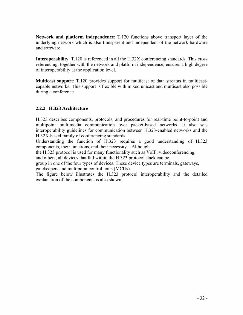
Network and platform independence: T.120 functions above transport layer of the underlying network which is also transparent and independent of the network hardware and software. Interoperability: T.120 is referenced in all the H.32X conferencing standards. This cross referencing, together with the network and platform independence, ensures a high degree of interoperability at the application level. Multicast support: T.120 provides support for multicast of data streams in multicast-capable networks. This support is flexible with mixed unicast and multicast also possible during a conference. syngress.com 2.2.2 H.323 Architecture H.323 describes components, protocols, and procedures for real-time point-to-point and multipoint multimedia communication over packet-based networks. It also sets interoperability guidelines for communication between H.323-enabled networks and the H.32X-based family of conferencing standards. Understanding the function of H.323 requires a good understanding of H.323 components, their functions, and their necessity. . Although the H.323 protocol is used for many functionality such as VoIP, videoconferencing, and others, all devices that fall within the H.323 protocol stack can be group in one of the four types of devices. These device types are terminals, gateways, gatekeepers and multipoint control units (MCUs). The figure below illustrates the H.323 protocol interoperability and the detailed explanation of the components is also shown.
- 32 -

www.syngress.com Graphical representation of H.323 Protocol Interoperability [12] 2.2.2.1 H.323 Terminals (Endpoints) A terminal is an endpoint where H.323 data streams and signaling originate and terminate. A terminal must support audio Communication; video and data communication support is not mandatory. This interface is contingent upon the application for which H.323 is being used. In the case of voice, the H.323 terminal is generally an IP telephone. In the case of video, the H.323 terminal is a videoconferencing terminal. H.323 is also widely deployed using computer. A very common application of the H.323 protocol can be found in the Microsoft NetMeeting software that allows for both voice and video transmissions on a User’s computer. For a device to be graded as an H.323 terminal, the device in question must have the following three components: A network interface, Audio codec, and H.323 software. All H.323 terminals support H.245 also, which helps in negotiating channel usage and capabilities.Q.931 helps in negotiating call signaling and call setup, while Registration/Admission/Status (RAS), a protocol which function is to communicate with a Gatekeeper; and support for RTP/RTCP for sequencing audio and video packets.
- 33 -

The figure below illustrate the various component that makes up the H.323 terminal and their connectivity with each other. It also describes the function of the components graphically.
H.323 Terminal graphical illustration [12]
2.2.2.2 H.323 Gateways A gateway is not a mandatory component in a H.323- network but a gateway is required at the interface when communication between different networks is required. A gateway contributes in providing a translation function between H.323 conferencing endpoints and other terminal types. The gateway has the characteristics of both an H.323 terminal on the H.323 network and the other terminal on the non-H.323 network it connects. A gateway may be able to support several simultaneous calls between the H.323 and non-H.323 networks. In addition, a gateway may connect an H.323 network to a non-H.323 network. This function involves translation between transmission formats (i.e. H.225.0 to H.221) and between communications procedures (i.e. H.245 to H.242), Gateway also translates between audio and video codecs and also performs call setup and clearing on both the LAN side and the switched-circuit network side. The major purpose of the Gateway is to reflect the features of a LAN endpoint to a switched circuit network (SCN) endpoint and vice versa. A gateway basic application includes:
- 34 -

• Provision of links with analog PSTN terminals. • Provision of links with remote H.320-compliant terminals over ISDN-based
switched-circuit networks. • Provision of links with remote H.324-compliant terminals over PSTN networks
Gateway manufacturers are left to incorporate many function on their own for instance the real number of H.323 terminals that can communicate through the gateway is not subject to standardization also, the number of SCN connection, the number of simultaneous independent conferences supported, the audio/video/data conversion functions, and inclusion of multipoint functions are left to the manufacturer. A gateway is a logical component of H.323 which can be deployed as a component of a gatekeeper or a MCU. The figure below illustrate a gateway and its functionalities
Gateway [12] 2.2.2.3 H.323 Gatekeepers
A Gatekeeper is the most valuable component of an H.323 enabled network. It performs the function of being a central point for all calls within its zone and also gives access to call control services to registered endpoints. Most times, an H.323 gatekeeper functions as a virtual switch. Gatekeepers perform two vital call control functions that include address translation from LAN aliases for terminals and gateways to IP or IPX addresses, as defined in the RAS specification. Bandwidth management, which is the second function of a gatekeeper, is also designated within RAS. For example, if a network manager has specified a threshold for the number of simultaneous conferences on the LAN, the Gatekeeper can refuse to make any more connections once the threshold is reached. The effect of this particular function is to reduce the total conferencing bandwidth to some fraction of the total available; the remaining capacity is left for e-mail, file transfers, and other LAN protocols. One feature of a gatekeeper that is not mandatory is its role in routing H.323 calls. Call routed via a gatekeeper can be controlled more effectively. Service providers require this particular function in order to bill for calls placed through their network. This service can also be used to re-route a call
- 35 -

to another endpoint if a called endpoint is unavailable. Gatekeeper also has the ability of routing H.323 calls that can help make decisions involving balancing among multiple gateways. Listed below are some of the functions perform by Gatekeeper.
Address Translation: Translation of alias address to Transport Address using a table that is updated with Registration messages. Other methods of updating the translation table are also allowed. Admissions Control: Authorization of LAN access using Admission Request, Confirm and Reject (ARQ/ARC/ARJ) messages. LAN access may be based on call authorization, bandwidth, or some other criteria. Admissions Control may also be a null function which admits all requests Bandwidth Control: Support for Bandwidth Request, Confirm and Reject (BRQ/BCF/BRJ) messages. This may be based on bandwidth management. Bandwidth Control may also be a null function which accepts all requests for bandwidth changes. Zone Management: The Gatekeeper provides the above functions for terminals, MCUs, and Gateways which have registered within its Zone of control. 2.2.2.4 Multipoint Control Units
The Multipoint Control Unit (MCU) helps to support conferences between three or more endpoints. MCUs is made up of several component which includes Multipoint Controller (MC), which is required, and zero or more Multipoint Processors (MP). The MC is use in performing H.245 negotiations between all terminals to determine common capabilities for audio and video processing. The MC also controls conference resources by determining which, if any, of the audio and video streams will be multicast.
The MC does not deal directly with any of the media streams it is the MP function to mix, switch and processes audio, video, and data bits. MC and MP capabilities can exist in a dedicated component or be part of other H.323 components. Multipoint conference abilities are performed in a variety of methods and configurations under H.323; it uses the concepts of centralized and decentralized conferences. Centralized multipoint conferences need the existence of an MCU to perform a multipoint conference. All terminals send audio, video, data, and control streams to the MCU in a point-to-point fashion. The MC centrally controls the conference using H.245 control functions that also define the capabilities for each terminal. The MP does the audio mixing, data distribution, and video switching/ mixing functions typically performed in multipoint conferences and sends the resulting streams back to the participating terminals. The MP may also provide conversion between different codecs and bit rates and may use multicast to distribute processed video. A typical MCU that supports centralized multipoint conferences consists of an MC and an audio, video, and/or data MP.
- 36 -

Decentralized multipoint conferences can make use of multicast technology. Participating H.323 terminals multicast audio and video to other participating terminals without sending the data to an MCU. Note that control of multipoint data is still centrally processed by the MCU, and H.245 Control Channel information is still transmitted in a point-to-point mode to an MC. The figures below illustrate MCU with its centralized and decentralized multipoint conferencing.
The Multipoint Control Units (MCU) [12]
Hybrid multipoint conferences describe this concept which uses a combination of centralized and decentralized features. H.245 signals and an audio or video stream are processed via point-to-point messages to the MCU. The signal that remains which could be audio or video is transmitted to participating H.323 terminals through multicast. H.323 also supports combine multipoint conferences in which some terminals are in a centralized conference, others are in a decentralized conference, and an MCU function as a bridge between the two types.
- 37 -

The figure below illustrates Hybrid and Decentralized conferencing.
Decentralized and Hybrid [12]
2.2.3 The H.323 Protocol Stack The H.323 protocol describes a series of protocols that work together to deploy end-to-end call functionality in a converged network. The H.323 protocol also depends mostly on the functions provided by other Protocols such as TCP, RTP, and UDP. The protocols that make up the H.323 protocol are Registration, Admission, and Status (RAS), H.245, and H.225.The protocols that make up the protocol stack and the protocols that H.323 depends on them which enable H.323 protocol to provide end-to-end call functionality will be discuss in details below. 2.2.3.1 Transmission Control Protocol TCP is a protocol that provides a reliable transmission control mechanism over the unreliable IP protocol. In order to perform the required function, TCP incorporates such mechanisms as sequencing, windowing, and reassembly of packets. In an H.323 network, TCP function is providing initial connection setup between H.323 endpoints and gateways/gatekeepers. 2.2.3.2 User Datagram Protocol UDP deploy an unreliable, unsequenced and connectionless protocol that provides reliability for speed. UDP depends on higher-layer protocols to perform sequencing
- 38 -

and reliability and also provides a much faster and lower-level transport protocol than TCP can. For this reason, UDP is used for the actual payload for VoIP calls. If a voice packet is lost or dropped, UDP disregards the lost packet, simply because delivering a lost voice packet out of synchronization will hinder rather than aid a call. 2.2.3.3 H.225 H.225.0 uses a subset of Q.931 signaling protocol for this purpose of Call signaling which is the main requirement required to set up and tear down a call between two endpoints. Q.931 was initially developed for signaling in integrated services digital networks (ISDN). H.225.0 adopts Q.931 signaling by incorporating it in its message format. H.225.0 call signaling is sent directly between the endpoints when no gatekeeper exists. When a gatekeeper exists then it may be routed through the gatekeeper. 2.2.3.4 H.245 The flexibility of H.323 demands that endpoints negotiate to determine compatible settings before audio, video, and/or data communication links can be established. H.245 uses control messages and commands that are exchanged during the call to inform and instruct. The deployment of H.245 control is compulsory in all endpoints. H.245 provides the following media control functionalities: • Capability exchange: H.323 enables endpoints to have different receive and send capabilities. Each endpoint takes care of its records, receiving and sending capabilities in a message and sends it to the other endpoint(s). • Opening and closing of logical channels: H.323 audio and video logical channels are uni-directional end-to-end links (or multipoint links in the case of multipoint conferencing). Data channels are bi-directional. A separate channel is needed for audio, video and data communication. H.245 messages control the opening and closing of such channels. H.245 control messages use logical channel 0 which is always open. • Flow control messages: These messages provide feedback to the endpoints when communication problems are encountered. 2.2.3.5 Registration, Administration, and Status RAS is a protocol used mainly between endpoints which can be terminals or gateways and gatekeepers. It performs the function of registration, admission control, bandwidth changes, and to disengage endpoints from gatekeepers.
- 39 -

2.2.3.6 Real-Time Transport Protocol RTP makes available an end-to-end network transport functions that is suitable for transmitting real-time data such as audio, video, or simulation data, over multicast or unicast network services. It is used to transport data through UDP but RTP does not address resource reservation and also gives no guarantee to QoS for real-time services. The data transport is augmented by a control protocol (RTCP) to allow monitoring of the data delivery in a manner scalable to large multicast networks and to provide minimal control and identification functionality. RTP and RTCP are designed to be independent of the underlying transport and network layers. The protocol supports the use of RTP-level translators and mixers. RTCP provides a control transport for RTP. RTCP provides feedback on the quality of data distribution and carries a transport-level identifier for an RTP source used by receivers to synchronize audio and video.
.
2.2.3.6 T.120
H.323 specifies T.120 services for data communications and conferencing within and next to an H.323 session. This T.120 support means that data handling can occur either in conjunction with H.323 audio and video, or separately. T.120 can use the H.225 layer to send and receive data packets or simply create an association with the H.323 session and use its own transport capabilities to transmit data directly to the network. Data from conferencing programs, such as file transfer and program sharing, use T.120 support to operate in conjunction with H.323 connections. Also, H.323-compatible products interoperate with data conferencing products developed under the T.120 specification.
- 40 -

The diagram below shows the various components that make up the protocol stack.
H.323 Protocol Stack [13] 2.2.4 Call Setup Call setup is a phenomenon that describes call processing events that occur during the time a call is being established, but not yet connected. The various procedures involved in creating an H.323 call are outline and explain below 2.2.4.1 Device Discovery and Registration When the discovery and registration stage of the H.323 call occurs, the gatekeeper establish a “discovery” process to find the gatekeeper which will communicate with the endpoint. This discovery can be either a statically configured address or through multicast traffic. Once the gatekeeper is found, the endpoint or gateway registers with the discovered gatekeeper. Registration is a process by which endpoints identifies a zone with which it can be Associated, while a zone is a collection of H.323 components managed by a single gatekeeper. H.323 function is to inform the gatekeeper of the zones’ transport address and alias address. The figure below shows the process of intrazone call placement.
- 41 -

H.323 Gatekeeper Call Control/Signaling: Discovery and Registration [11] Two actions take place in the figure below which portraits intrazone call placement. The first action is that the H.323 gateway forwards a request to register (RRQ) message using H.225 RAS on the RAS channel to the gatekeeper. The second action is when the Gatekeeper acknowledged the registration by forwarding a registration confirmation (RCF) or a “Reject registration” message back to the gateway. 2.2.4.2 H.323 Call Setup After discovery and registration, then call placement are successfully completed, the H.323 calls translate to the call setup stage. Within this stage, the gateways are communicating directly to set up the connection. Another method of call setup is Gatekeeper-routed call Signaling, where all the call setup messages passes through gatekeeper. The figure diagram below helps to explain the call setup process.
- 42 -

CCA. CALL SETUP ILLSUTRATION [11] The setup protocol depends on Q.931, and the setup message involves caller name and IP address. The call setup depends on the ITU-Q.931 and H.225 is a subset of Q.931, this deploys a way to establish, maintain, and terminate network connections across an ISDN. Using the above figure, this process involves six different phase PHASE ONE: Gateway X forwards an H.225 call-signaling setup message to Gateway in order to request a connection. PHASE TWO: Gateway Y forwards an H.225 message back to Gateway X, telling gateway X to carry on with the call. PHASE THREE: Gateway Y forwards an RAS message (ARQ) on the RAS channel to the gatekeeper to ask for permission to acknowledge the call. PHASE FOUR: The gatekeeper confirms that the call can be acknowledged by sending a message (ACF) back to Gateway Y. PHASE FIVE: Gateway Y forwards an H.225 message to Gateway X, signaling that the connection has been established. PHASE SIX: Gateway Y forwards an H.225 message to Gateway X, confirming the call connection and the call are established. www.syngress.com 2.2.4.3 Logical Channel Setup After call setup, all communications passes through over logical channels. The H.245 protocol is now used to define procedures for managing these logical channels. Multiple logical channels of varying types (video, audio, and data) are allowed for a single call. The H.245 Logical Channel Signaling Entity (LCSE) opens a logical channel
- 43 -

for each media stream. Channels may be unidirectional or bidirectional. The Figure below helps us to visualize how the H.323 uses virtual channels.
Media channel Setup [11] 2.2.4.4 Call Termination Call termination helps to stops the media streams and closes the logical channels. It may be requested by any endpoint and it also ends the H.245 session, release H.225/Q.931 connections and deploy disconnect acknowledgement to the gatekeeper through RAS. The Figure below illustrate call termination flow
Illustration of Call Termination (H.245/H.225/Q.931/RAS) [11]
- 44 -

The following phases defined the above illustration PHASE ONE: Gateway Y establishes the call termination by forwarding an H.245 End Session Command message to Gateway X. PHASE TWO: Gateway X releases the call endpoint and acknowledges the release by forwarding an H.245 End Session Command message back to Gateway Y. PHASE THREE: Gateway Y completes the call release by forwarding an H.245 Release Complete message to Gateway X. PHASE FOUR: Gateway X and Gateway Y disengage with the gatekeeper by sending a RAS DRQ message. PHASE FIVE: The gatekeeper disassociated and acknowledges the message by forwarding DCF messages to both Gateway X and Gateway Y. 2.2.5 Session Initiation Protocol
Session Initiation Protocol (SIP) is the Internet Engineering Task Force's (IETF's) standard used for the purpose of multimedia conferencing over Internet Protocol. SIP is an ASCII-based, application-layer control protocol (defined in RFC 2543) that can be used to establish, maintain, and terminate calls between two or more end points.
SIP is developed to take care of signaling and session management within a packet telephony network. Signaling makes call information to be carried across network boundaries. Session management provides the need to control the attributes of an end-to-end call.
SIP provides various functions as outline below
• SIP determines the location of the target end point and also helps in address resolution, name mapping, and call redirection.
• SIP determines the media capabilities of the target end point through Session Description Protocol (SDP); it also determines the "lowest level" of common services between the end points. Conferences are initiated using only the media capabilities that can be supported by all end points.
• SIP determines the availability of the target end point. When call cannot be through because the target end point is unavailable; SIP takes care of the problem, finding out whether the called party is already on the phone or did not answer in the allotted number of rings. It then sends a message showing the reason the target end point was unavailable.
• SIP initiates a session between the originating and target end point, if the call can be completed, SIP initiates a session between the end points and also supports mid-call changes, such as the addition of another end point to the conference or the changing of a media characteristic or codec.
- 45 -

• SIP handles the forward and termination of calls and also takes care of call forwarding from one end point to another. During a call transfer, SIP simply establishes a session between the transferee and a new end point (specified by the transferring party) and terminates the session between the transferee and the transferring party. At the end of a call, SIP terminates the sessions between all parties. SIP is an open, standards-based protocol which is widely supported and is not dependent on a single vendor’s equipment or implementation. SIP is a newer protocol than H.323 and does not have maturity and industry support at this time. However, because of its simplicity, scalability, modularity, and ease with which it integrates with other applications, this protocol is attractive for use in packetized voice architectures. SIP is complementary to MGCP in that MGCP provides for device control while SIP handles session control.
Some major benefits of SIP are outline and explain below,
Simplicity: SIP is a simple protocol. Its software development time is very short compared with that of traditional telephony products. SIP code reuse is possible because of its similarity to HTTP and SMTP. Extensibility SIP has developed a rich set of extensibility and compatibility functions through learning from HTTP and SMTP. Modularity SIP was developed to be highly modular. A major characteristic is its independent use of protocols. For instance SIP issues invitations to called parties, independent of the session itself. Scalability SIP offers two scalability advantages: Server processing SIP has the capability to be either stateful or stateless. Conference sizes Since there is no requirement for a central multipoint controller, conference coordination can be fully distributed or centralized. Integration SIP has the capability to integrate with the Web, e-mail, streaming media applications, and other protocols. Interoperability Because it is an open, RFC-based standard, SIP can offer interoperability between different vendor’s platforms seamlessly. www.syngress.com 2.2.6 Session Initiation Protocol Components The SIP architecture is made up of two components which are user agents and network servers. A user agent (UA) is SIP’s endpoint or terminal, which is used in making and accepting SIP calls. The client which is known as the user agent client (UAC) is used to initialize SIP requests.
UAS is the Server takes care of the application that is responsible for accepting the SIP requests from a UAC, and on reception returns a response to the request back to the UAC. The component that makes up SIP includes IP phones acting in the capacity as
- 46 -

either UACs or UASs, gateways provides call control for a VoIP environment in SIP implementation.
SIP Architecture [14]
A SIP server is made up of three serves as outline and explains below,
Proxy server: Proxy servers handle the issue of which server a request should be sent to and then send the request. The request at times passes through many SIP servers before getting to its destination and the response actually passes through a reverse order. A proxy server can act as both a client and server and can issue requests and responses. Redirect server :The main function perform by the redirect server is to signal the calling party of the actual location of destination or it supplies the client with information about the next hop or hops that a message should take and then the client contacts the next hop server or UAS directly. Registrar server: It takes care of registration services for UACs for their current locations. Registrar servers are always sited alongside with proxy and redirect servers. www.syngress.com 2.2.7 Session Initiation Protocol Messages SIP performs its function based on client and server architectural operation. A unique address is used to differentiate a client from another client and these addresses come in a format that resembles e-mail addresses SIP message structure is the same as HTTP-like request/response transaction model. Any of these transactions consists of a request that involves a particular method, or function,
- 47 -

or the server and at least one reponse.SIP message is made up of two types as explain below There are two types of SIP messages Request: Request is a message sent from the client to the server. SIP request are categorized into many method which are describe below 1. INVITE: Invite initiates a call, changes call parameters 2. ACK: Confirms a final response for invite 3. BYE: Terminates a call 4. CANCEL: It cancels search and ringing 5. Options: Queries the capabilities of the other side 6. REGISTER: Registers with the location service Responses Response message contain numeric response codes. The SIP response code set is partly based on HTTP response code. Provisional and final Reponses are two types of responses, responses also has six classes Provisional response which are used by the server to indicate progress, but they do not terminate SIP transactions, it belongs to class 1xx. A final response terminates SIP transactions which comprise class 2xx, 3xx, 4xx, 5xx, and 6xx. The classes are listed below with their description 1.1xx: Provisional, searching, ringing, queuing 2.2xx: describes success 3.3xx: describes redirection and forwarding 4.4xx: describes server failures (client mistake) 5.5xx: explains server failures 6.6xx: explains global failure SIP message is made up of three parts, the parts are explain below Startline: Startline starts every SIP message; it conveys the message type and the protocol version. The startline may be either a request-line or a status-line. Request-line includes a request URL, which indicates the user or service to which this request is being addressed. The status-line holds the numeric status-code and its associated textual phrase. Headers: SIP header field is used for message modification and convergence of message attributes. They are likely in syntax and semantics to HTTP field’s .Header can span multiple lines. Some SIP header such as via, contact, Route and request. Route can
- 48 -

appear multiple times in a message or alternatively can take multiple comma separated values in a single header occurrence. Body: A message body describes the session to be initiated. It can also used to contain opaque textual or binary data of any type which relates in some way to the session. Message body can be in form of request or response messages. SIP makes a clear distinction between signaling information, conveyed in SIP startline and headers, and the session description information. 2.2.8 Skinny Client Control Protocol Skinny Client Control Protocol is a proprietary terminal control protocol first invented by Selsius corporation but now owned and defines by Cisco systems Inc, Skinny is a lightweight protocol which allows fro efficient communication with Cisco callmanager. A skinny client uses TCP/IP to and from one or more call managers in a cluster. RTP/UDP/IP is used to and from a similar Skinny client or H.323 terminal for the bearer traffic (real-time audio stream).SCCP is a stimulus –based protocol and is designed as a communication protocol for hardware end point and other embedded systems, with significant CPU and memory constraints. SCCP technology was acquired by Cisco when they acquired Selsius corporation in 1998. Considering solution, the end station of a LAN or IP-based PBX must be simple to use, familiar and relative cheap. SCCP defines a simple and easy to use architecture, while the H.323 recommendations are quite expensive system. An H.323 proxy can be used to communicate with the skinny clients using the SCCP. In the SCCP architecture, the vast majority of the H.323 processing power resides in an H.323 proxy. The telephone which is the end points run what is called the skinny client which consumes less processing overhead. The client interacts with the call manger using connection oriented (TCP/IP-based) communication to establish a call with another H.323-complaint end point. Immediately the call is initiated by the call manager, the two H.323 endpoints uses connectionless (UDP/IP-based) communication for audio transmission cost and overhead is thus reduced by confirming the complexities of H.323 call setup to the call manager, and using the skinny protocol for the actual audio communication into and out of the station. Cisco call manager acts as an H.323 proxy and handles the H.323 protocol and takes on the majority of call control, which reduces the burden on the phone and wireless network SCCP provides proprietary VoIP messaging between Cisco IP phones and Cisco call manager.SCCP uses TCP/IP for data transport but RTP and UDP convey the call directly between endpoint after connection is made.
- 49 -

2.2.9 Comparing SIP and H.323
H.323 and SIP are the two signaling protocol that are competing for the dominance of IP telephony signaling, choosing the appropriate one to make use of depends entirely on what application you want to run. The two protocol suites appear to be merging, coping good ideas from one another.
Most importantly, there is still some setback suffered by some of the protocol which makes them not suitable for some application.
The major comparison that arises between SIP and H.323 lies in their functionality, scalability, interoperability and quality of service.
The comparison will be make below and the protocol to be used for a particular application will be clearly understand after going through this compares.
Architectural
Taking architectural point of view, H.323 handles every service which involves features like capability exchange, conference control, basic signaling, QoS, registration, and service discovery, while SIP modular architecture which means that it handles the basic call signaling, user location, and registration.
Philosophy
H.323 was developed basically for the multimedia communication over IP networks. It describes an entire, unified system for performing these functions, leveraging the strengths of the IETF and ITU-T protocols. H.323 was developed to have room for new functionality. The application that makes use of H.323 mostly is Voice over IP followed by Videoconferencing, both of which are described in the H.323 specifications. SIP was developed to be modular and also to setup a session between two terminals. It has no support for multimedia conferencing, and the integration of sometimes disparate standards is largely left up to each vendor.
Scalability
H.323 was developed initially for LANs support, so it was not meant for wide area addressing. Zone concept was incorporated to take care of wide area addressing. Annex G described communication between administrative domains; it also describes ways to allow for address resolution, access authorization and usage reporting between administrative domains. In multi-domain searches, loop detection performance is not easy. Taking care of the loop detection can be done but it brings about other problems like scalability. SIP was designed to supports wide area addressing. Whenever many servers are included in a call setup, SIP uses a loop detection procedure that resemble the one used in BGP, which can be done in a stateless manner, thus avoiding scalability issues. The SIP Registrar and redirect servers develop to support user location.H.323 call
- 50 -

control can be deployed in a stateless manner. A gateway makes use of messages described in H.225 to help the gatekeeper in handling load balancing across gateways. Call control can be implemented in a call stateless manner. SIP supports n to n scaling between UAs and servers and also takes less CPU cycles to generate signaling messages which will make the server to handle more transactions. SIP has defined a procedure of load balancing which depends on the DNS SRV record translation mechanisms.
Complexity H.323 base specification amount to 736 pages excluding its ASN.1 and PER while SIP together with its call control extension and session description protocols has base specification that is equal to 128 pages making it less complex than H.323. Base on ASN.1 and the packed encoding rules (PER), H.323 make use of binary representation for its format for messaging. SIP encodes its message as a text which is similar to HTTP and RTSP and because of this style of encoding by SIP, it brought about simple parsing and generation which makes it less complex than H.323 protocol. H.323 ability of using many components in to accomplice one task also adds to its complexity. A service like call forwarding for example requires several components that includes H.450, H.225 and H.245 in order to be carried out. SIP protocol makes use of a single request that incorporate all the necessary information required to accomplice a demanded service.
Reliability
A good number of features are incorporated in H.323 protocol in order to take care of failure of intermediate. This features includes alternate gatekeepers, alternate endpoints and also it also has a means of recovering from connection issues. SIP as the time of this work is yet to define a methodology that will handle device failure. For instance when a proxy serve fails, it is the responsibility of the user agent to forward a re-INVITE to another proxy which contributes to a long call delay in call initialization.
.
- 51 -

Chapter Three VoWLAN Requirement 3.1 VoWLAN Requirements: Analysis IP technology introduces another form of challenges in designing a voice system. In order to design a system that will ensure quality services, there is need to know beforehand how many voice channels that a company needs and thus design a system that can support such. To determine the number of voice calls a packet network can easily support, it is very important to know the amount of capacity the network guarantees to provide on a route and also the number of bits per second for each voice channel needed. The knowledge of this will ensure that too many voice calls are prevented from being sent. Another factor to be considered is the WLAN infrastructure, a decision is to be made whether to deploy a spot coverage or a total facility coverage. With a spot coverage, there is coverage in selected areas within the company thus only provides services within these areas, while a total facility coverage covers all the areas within the company thus services can be accessed from any part of the company. Also to be considered is the distribution and placing of access points to provide network coverage, while a single access point and WLAN channel can serve an office, in order to build a large –scale, enterprise-grade WLAN a centrally controlled WLAN switch is needed . Then the issue of Quality of Service (QoS) is also very important in designing a VoWLAN system: in a WLAN network, all the users within the range of a given Access Points vies for access to a single shared radio channel on the basis of contention. These traffic from all the contending users are carried on a low-capacity, half duplex radio link, this makes the network jitter and delay worst. Thus the issue of Quality of service (QoS) can be introduced through the following quality issues: 3.1.1 Voices Quality The quality of voice received is dependent on the percentage of packets that are dropped by the network and also the voice encoding system used. Packet loss/drop can be caused by buffer overflow outside of the RTP receive jitter window. 3.1.2 Transit Delay In a network, packet do experience delay on transit to the receiver, the length of this delay determines the effect of the quality of service of the network and these delays are generally longer for a WLAN network. Networks are designed to allow a certain range of delay beyond which the voice quality is affected. Between the speaker and the receiver, once a one-way delay is in excess of 100 MSec, the cadence of the conversation will begin to be affected, when in excess of 150msec, it will certainly lead to user complaints. For a WLAN network, experiment has shown that forwarding voice introduces an additional 20 to 30msec of delay. Then
- 52 -

looking at jitter, which is the variation in packet –to-packet delay that results from the dynamic allocation of network capacity, to remove it, RTP is used. But this process, the RTP buffering process, in itself adds to the overall transit delay. For VoIP devices that uses fixed-size jitter buffer, the problem is more since packets received outside their time window are dropped, this in turn degrades the voice quality. Thus using adaptive jitter buffers are recommended for WLAN voices systems. 3.1.3 Echo Control This is one effect that is usually present in all voice packet networks. For echoes in excess of 35 to 40msc, it becomes noticeable, thus must be removed using equipment. This echo control must be incorporated into the voice system for a good voice quality. 3.2 The IEEE802.11e WLAN MAC Qualities of Service enhancements Considering voice services in WLAN, QoS is very important since poor quality means poor communication. To enhance QoS, the IEEE 802.11e, which was ratified in 2005, defines a new MAC option that provides a QoS capability within the WLAN structure. Stations can vie for the channel using either of the mechanisms. The options defined in the new standard are as following:
1. The Enhanced Distributed Channel Access (EDCA)/ Wi-Fi Multimedia (WMM):
This is a contention-based access mechanism with four priority levels or access categories that has the capacity to provide voice users with preferred access to the shared channel. The four user priority options in EDCA/WMM are implemented by enhancing two mechanisms from the original WLAN access protocol, there are the inter-frame spacing and the back-off counter. In EDCA, different waiting intervals and back-off ranges for each of its four access categories, assigning shorter intervals to higher priority access categories. This is against the old/traditional WLAN where all the user have same access priority since they all use the same Distributed Control Function (DIFS) internal and also the same range of back-off values to address collision and busy channel conditions. EDCA/WMM defines the following four priority categories: Access category (AC) 1: Voice Access category (AC) 2: Video Access category (AC) 3: Best effort data. Access category (AC) 4: Background data. Here AC 1 and 2 has shorter intervals than the normal DIFS , AC 3 has same interval while AC 4 has longer interval.
- 53 -

text
text
text
text
3-7 TIME SLOTS
7-15 TIME SLOTS
15-1023 TIME SLOTS
15-1023 TIME SLOTS
SIFS
10µsec + 2 Time slots
10µsec + 2 Time slots
10µsec + 3 Time slots
10µsec + 7 Time slots
1
2
3
4
ACCESS CATEGORY
TIME SLOT DURATION FOR 802.11a/gµsec
IEEE 802.11e Default Parameters (802.11a/g) [3] 3.2.1 Collision Avoidance When using EDCA/WMM , in a case where a voice or video user is trying to access the channel at the same time as a best effort user, then the voice or video user is always the one to send first, thus avoiding collision between a voice and data user. However, this is not so where two voice users or a voice and video user is involved, there can still be a collision in this case. Also stations, irrespective of their categories could also collide if their nodes are hidden. The 802.11e also specified different ranges for the back-off counters, in the event of collision occurring between a higher priority transmission will select a longer interval. Thus, the voice frame, with a shorter waiting interval has preferred access to the channel, but the access point needs also to be able to differentiate a voice frame, so the frame can be forwarded to the wired LAN part with the right priority.
2. The HCF Controlled Channel Access (HCCA)/Wi-Fi Multimedia – Scheduled Access (WMM_SA):
The Hybrid Coordination Function (HCF), IEEE802.11e function defines a polled or contention-free access known as Hybrid Controlled Channel access (HCCA). The access point or hybrid coordinator in HCCA, controls the channel by way of sending a field in the beacon message which causes all stations to set their Network Allocation Vector, NAV timers; at this instance, all stations assumes that the channel is busy for that period of time.
- 54 -

For a time sensitive traffic, the access period declares a contention-free access point and also determines the required duration of that contention-free interval based on the number of stations receiving HCCA access, the transmission requirements and transmission rate for each. Then, during the period when the system is in the contention-free periods, stations with time sensitive traffic are polled to send by the access point, which is almost the same mechanism as in Point Control Function, PCT , though with the following enhancements:
1. Transmission profile that specifies the requirement for bandwidth, jitter and latency are requested for using the Tspec signaling protocol by the stations.
2. An equivalent of busy signal is returned in the event that access point does not have sufficient capacity to meet the requested profile.
3. In the event that the connection can be supported, the station will be assigned a slot in the access point’s polling table and the contention-free interval will be increased by the required amount. It is only when polled that HCCA stations can transmit.
4. The stations are polled at each round of a contention-free cycle and a disconnect message is send to the access point when the connection is no longer needed and its entry are removed from the polling table.
text textPoll 1 ACK Poll 2 textACK
textFrame
textFrame
BeaconAccess Point
HCCAStations:1
HCCAStations:2
Contention- free Period Contention- BasedAccess(EDCA)
Hybrid Control Channel Access (HCCA) [3]
- 55 -

The down side of using HCCA is in its effect on the capacity and delay experienced by non-HCCA users, since all contention-based traffic are squeezed into some percentage of the available transmission time. Thus, the longer contention-free period there is, less capacity there will be available for the non-contention-free users.
3.2.2 Capacity and Quality of Service The capacity of Voice on WLAN network looks at the number of voice users that a network is capable of supporting simultaneously which the QoS looks at the quality experienced by the users. Capacity and QoS are treated jointed since the issue of providing adequate capacity while at the same time minimizing transit delay and jitter can be taken care of by increasing the overall network capacity or by just ensuring that voice packets are recognized and thus given priority treatment over data packets, thus ensuring QoS for users while keeping the capacity high. Determining the number of simultaneous calls a network can handle has be difficult, but vendor recommendations range from 6 to 14 simultaneously calls on an 11 Mbps network. But this is for a network using 802.11b implementation, thus with an 802.11 implementation the capacity will be increased to support more calls. Again the actual number of calls will normally vary depending of the RF coverage the user is recovering.
text
802.11b Network 802.11a or g NetworkCodec
G.711
G.729A
G.723.1
SKYPE iLBC
11Mbps 5.5 Mbps 2 Mbps 1 Mbps 54 Mbps 36 Mbps 18 Mbps 6 Mbps
23
30
44
28
16
24
36
22
8
14
21
13
8
4
13
7
78
92
138
89
69
86
129
83
51
73
110
69
24
45
66
40
Theoretical Maximum Calls per WLAN (20 msec Voice Sampling) [3]. Then looking at the impact of 802.11e EDCA/WMM, the 802.11e EDCA/WMM implementation makes provision for capacity reservation for voice and video or gives
- 56 -

priority to voice and video services to the shared radio channel. This in itself does not increase the number of voice calls, but the QoS it provides will encounter, thus the effect is a better voices calls than more voice calls. In implementing thus, care must be taken to ensure that data traffic are not squeezed out since increasing the voice reserved capacity means reducing the data traffic capacity and since the network is designed for both care must be taken to protect data traffic.
3.3 Analysis of VOWLAN design factors/elements In analysing the requirements, we look at both the Voice and data traffic need of the company, the security need, the number of prospective users, the need for roaming, and other needs which will help particularly serve the company. To achieve this, we identified three steps to analysing the VoWLAN requirement of a company:
1. Identify the potential VoWLAN requirement:
At this stage, the number of users, the applications to be also used on the WLAN, the network utilisation, the roaming need, and the coverage areas are identified. 3.3.1 The Number of users The number of users who will be accessing the network, using IP phone, laptop or other network devices is important to ensure proper network configuration and properly size the network. Knowing the number of users and their locations within the company will also help in properly distributing the network among the users. 3.3.2 The Application The applications to be used in the network, whether it’s a voice only network or for both data and voice traffic network. For our study, we considered a voice and data traffic network. Other applications such as web browsing, web video viewing, file transfer, price marking for a retail store, wireless patient monitoring for a hospital are to be also taken into consideration. 3.3.3 Network Utilization Network utilization is important for efficiency, thus locating the Access Points, AP to ensure proper utilisation and thus efficiency of the network. In a wireless situation, the location of the AP is important with the company, as users move freely and can transmit from any point, but not simultaneously using the same AP, they must take turns to transmit, thus limiting the performance as the number of network users increases. Properly assessing the current and projected network utilisation will help in properly locating APs and thus properly distribute the traffic load. For instance, a conference room where the top management usually meet, its important the enough APs be provided to handle needs which may arise in the cause of the meeting , for instance many managers needing the use of IP phones at the same time. This is also true with offices where IP Phones are in constant use.
- 57 -

3.3.4 Roaming Weather all users are to be stationary or mobile is to be part of the requirements to be considered, this will better inform the network designer during configuration. For instance, it could be configured to allow some users to roam across IP domains, but this also presents the need to manage IP addresses dynamically; while others are configured to be stationary, using desktop computers. Roaming delays are also to be considered at this stage, VoIP phones normally accept a roaming delay of 100milliseconds or less, but since the network will also be used for data applications, there is bound to be longer delays. 3.3.5 Coverage Areas A proper ulitilisation analysis will help in determining the coverage area and also avoid the needless expenses of providing access where it’s not needed, coverage area generally impact channel planning. Consideration here is given to other special areas, apart from the obvious areas where network is to be provided. These areas include Stairwells, restrooms, Utility rooms, basements and elevators. 3.3.6 Stairwells Fireproofing materials, steel-reinforced concrete, etc generally block radio waves, thus network reception in the stairways is poor and cannot support voice traffic. Thus where the network importance outweighs the cost, access points are to be provided on each floor to provide adequate network for VoWLAN services. 3.3.7 Restrooms The need to cover the restroom is limited, except for critical enterprises like hospital, the restroom is not covered. Utility rooms: There may be the need to ensure network coverage inside the utility room so that for instance, an IT personnel can communicate with a higher staff while working ( e.g. troubleshooting)inside the utility room. Basements: Many companies makes varied use of the basement, thus there maybe the need to provide network coverage at the basement to support such uses or to provide VoWLAN services while at the basement.
- 58 -

Chapter Four VoWLAN Design 4.1 Voice on Wireless Local Area Network solution: Design Designing a VoWLAN solution involves exposes how the technical elements of a system will meet the requirements for the solution and properly documenting them. This also involves making the appropriate element selections that will ensure that the service requirements are met. The system requirements as already discussed in the last chapter is the basis for making the important decisions on which technologies and configuration settings the system will be made of. According to Jim Geier, in Deploying Voice over Wireless LANs, the steps for designing a VoWLAN system are as follows: Step 1 Specify the overall system architecture. This step involve selecting a well-tested model that indicates how the necessary components will interact, specifying how roaming will work , determing security and Quality of Service elements, and defining the network infrastructure. Step 2 Identify access point installation locations. This step involves active testing within the facility to identify the optimum installation location for each access point. Step 3 Document the design. Documenting the design is very important. This documentation is a valuable reference when installing the system and also when supporting the system. 4.2 Deployment Models There are many types of models to be used for deploying wireless voice system, these includes the single-site architecture, the multiple WAN with centralised call processing architecture, the multiple WAN with distributed call processing architecture, etc. When making the choice of the wireless voice system to be used, it is preferable to base it on a model that has been well tested and also one that is from the same manufacturer as the IP phones to be used. Below is a brief description of some of the models: 4.2.1 The Single-Site Model This model is best suited for companies with fewer phone lines, that’s about 30,000 lines. It has a call processing agent located at a single site with wireless LAN used for carrying voice traffic. With this model, when a call is placed to a receiver outside the coverage of the Wireless LAN, the Public Switched telephone Network must be used. The main advantages of the single-site model are in its easy of deployment and requires lower budget. This is especially so as the model does not require a WAN in order to interconnect users with the call processing agent and also a common local infrastructure is responsible for call control and voice traffic. In deploying a single-site model, the following maybe considered:
1. To make the system’s dial plan configuration simple, Media gateway Control Protocol can be used instead of the H. 323 protocol if there is no apparent need for it [1].
- 59 -

2. The single-site model is best suited for a situation where all the calls are within site or calls are destined for PSTN users outside the company [1].
3. There is need to include G. 711 codecs for all endpoints. This will help reduce the phone’s processor consumption for transcoding signals, thus enables the processor handle other functions.
ISDN NETWORK
MCUs
Gatekeepers
Applications
CallManager cluster
H.320 Gateways
Voice Gateways
Single-Site Model for the CISCO VoWLAN System [1]
- 60 -

4.2.2 The Multi-site WAN with Centralized Call Processing Model This model is best for companies with more than 30000 phone lines. The model has a centralised call processing for its multiple sites, thus since there multiple sites, the call processing packets must flow over the WAN. The use of WAN poses its own threat to the reliability of the calls, since any WAN outage will disrupt calls within each site and the WAN must be able to support a certain minimum level of speed, 768 kbps per connection according to Jim Geier, in Deploying Voice over Wireless LANs. Reliability of the WAN should be the major concern, so effort should be made to strengthening the reliability of the WAN for multiple site model architecture. To improve the WAN reliability, the following are recommended:
1. Survivable Remote Site Telephony (SRST):
This approach is designed to be used when WAN fails but only provides reliability for voice services and not data services. When the WAN is functional, the branch office connects over WAN to the Call Manager at the central site, thus it’s the WAN that will carry the Voice signals, data traffic and voice traffics. SRST works in such a way that if a WAN failure occurs, the wireless IP phone rehome to call processing functions available in the local router. That is the wireless IP phone, registers with the local router, which allows internal calls to be placed and also connects external calls over the PSTN. At this point, some of the features available for a WAN system but not for a PSTN system will not be available and the user will be informed with a display message ‘Unified CM fallback Mode’. Then when the WAN is re-established, the wireless IP phone will automatically reregister with the Call Manager at the central site[1].
- 61 -

CallManager cluster
IP WANPSTN
Voice Traffic
CallManager cluster
ISDN Backup
ISDN Backup
IP WAN
PSTN
Voice Traffic
Signalling
Signalling
Branch Office
Branch Office
Central office Central office
SRST Operation in the Presence of a WAN Failure [1]
2. Redundant IP WAN links in the branch router:
This provides IP WAN links that are redundant when the WAN is working but enables the system to continue working when the WAN goes down, thought cannot survive the total loss of a branch router.
3. Data and Voice ISDN backup:
In this approach, the branch router is configured to provide backup connection to the ISDN that will in the event that the WAN going down, maintain voice traffic, call signaling, and data flowing between the central office and the branch office. For this approach to be effective, it requires that the bandwidth requirement of the voice traffic is equal or less than the ISDN bandwidth allocation[1].
4. Survivable Remote Site Telephony (SRST) with ISDN backup for data:
This approach is an advancement of the original SRST approach, with its provision for data backup which is not available with the original SRST. This is done by interfacing the branch router with the ISDN (Integrated Services Digital Network), though there a need to configure the ISDN connection so as not to allow Simple Client Control Protocol (SCCP) traffic from the Wireless IP phone to enter the ISDN interface.
- 62 -

4.2.3 Multi-site WAN with Distributed Call Processing The Multisite WAN with Distributed Call Processing architecture model is best for large sites with a maximum of 30,000 phone lines each, mostly with a maximum of six large sites. The model has multisite all with a call processing agent at each site. Thus in this architectural model, when there is a WAN failure in a site, it does not affect calls in order WANs. Then to offer some improvement, just like in the order models, in addition to those methods for improving the other models, the following also offers significant improvement for the Multisite WAN with Distributed Call Processing model: The Session Initiation Protocol (SIP) proxies: In designing the system, there is need to ensure that the SIP proxies have adequate redundancy and also that the SIP proxies have the capacity for the rate and number of calls required in the network. 4.3 Call processing Agents Consider the possibility of using different call processing agents at each site. Call processing Agent Recommended Size Comments Cisco Unified Call Manager Express(CME)
Up to 240 phones For small remote sites Capacity depends on Cisco IOS platform
Cisco Unified Call Manager 50 to 30,000 phones Small to large sites, depending on the size of the Cisco Unified Call Manager cluster. Supports centralized or distributed call processing.
Legacy PBX with Voice over Internet Protocol(VoIP) gateway
Depends on PBX Number of IP WAN calls and functionality depends on the PBX-to-VoIP gateway protocol and the gateway platform.
Recommended Call Processing Agents [1] Gatekeepers This is an H.323 device which provides Call Admission Control and also E.164 dial plan resolution. To improve on the multisite with distributed call processing, consider using Hot Standby Router Protocol (HSRP) gatekeeper pairs, gatekeeper clustering and alternate gatekeeper support to provide a higher reliability of the gatekeeper[1].
- 63 -

Network Capacity Analysis In analyzing the capacity of a network, consider the coverage area that each Access Point will produce around its location. Since voice services is of higher load than data, configuring the Access Points in order to produce the largest cell size/coverage area will not produce an efficient network for voice services, rather, the better method is to determine the maximum number of simultaneous voice devices that will be operating on the network, this will help to determine the number of access points that can effectively support voice traffic. Thus, in order to create a wireless LAN network with capacity to support voice call requires that the access point’s cell size are reduced, in this way the capacity of the wireless network is increased. In other words, this method leads to having access points serve just fewer users, thus resulting in an improved capacity and performance of service. Capacity analysis also involves using the defined requirement for the number and placement of voice users and also their corresponding network utilisation. For instance, to arrive at the access point density to use for a particular area, the number of simultaneous voice users within the area. In doing this, first determine the coverage area to be covered, and then determine the number of access points and the radio cell size. The maximum number of simultaneous calls that a network on 802.11b can support is 8[1], thus the area to be covered is divided in such a way that the access points are located at the optimum points and configured at reduced radio cell size to support high performing voice service. A good example is a conference room that is expected to support a maximum of 30 simultaneous voice users. Here since an access point can only support a maximum of 8 users, then about 5 access points are needed for the conference room which has the capacity to support up to 35 simultaneous users. Then, the access points are configured to cover not more than one third of the total area. In this way the whole area is covered, but efforts must be made to ensure that users outside the conference room do not connect to the access points set aside for conference usage. Using the new 802.11n will offer a larger network, more user’s capability and also better efficiency and QoS. 4.4.1 Radio Frequency Site Survey Taking a point radius around a radio antenna, it will be discovered that there is a varying degree of attenuation due to different obstacles, thus causing the radio frequency radiation pattern around the antenna to be irregular and unpredictable. Thus, the need to conduct an RF site survey of a company’s facility to get a grasp of the behaviour of the radio waves to aid in properly locating the access points. An RF survey will help in revealing information necessary to determine among other things, the placement of the access points, and the number of access points needed to provide adequate coverage throughout the whole company’s facilities that needed coverage. A proper survey will also detect the presence of any form of interference that could degrade the performance of the wireless LAN. A proper survey also will eliminate the need to relocate and/or add new access points within the facility after installing and interconnecting many access points that may arise due to interference, inadequate coverage and/or low performance in some areas.
- 64 -

The following tasks are recommenced to be performed when conducting an RF survey [1]: 1. Obtain a facility Diagram. A comprehensive company layout blueprint, with detailed facility plans is needed in carrying out a site survey. Thus, the first step is to get hold of it. 2. Make a Visual inspection of the facility: Start with a walk through the facility with the aim of confirming the blueprint, look out for major obstacles that can interfere and/or be a barrier with RF signal propagation and also look out for potential installation points. 3. Identify user areas: On the facility diagram, mark the areas fixed and mobile users. In addition to illustrating where mobile users may roam, indicate where they will not go. 4. Determine preliminary access point locations: Considering the location of wireless users and range estimations of the wireless LAN products you are using, approximate the locations of access points that will provide adequate coverage throughout the user areas. Plan for some propagation overlap among adjacent access points, but keep in mind that channel assignments for access points need be far enough apart to avoid interaccess point interference. 5. Gather tools: In gathering tools, an access point is needed for testing, the access point is configured to the same setting as the deployment design, especially the transmit power. Thought its good to use this stage to determine the mist suitable transmit power for the access points in the design conditions and also the antenna type to be used to produce the design radio cell size that is required to support the designated number of and utilisation of users. 6. Verify Access Point locations: This is the major step in testing the network design. Use the free tool kit, that is usually included by the equipment manufacturers, to identify the data rate, signal strength, associated access point and signal quality. 7. Install an access point at each preliminary location, and monitor the site survey
software readings by walking varying distances away from the access point. 8. Identify the client devices: Its is convenient to start by determining the client device that has the lowest Effective Isotropic Radiated Power (EIRP). Also identify the client device with the lowest association signal strength. Thus ensure that the client devices to be installed will ensure two-way communications in all covered areas for that which has the lowest EIRP or weakest uplink signal with connected/associated with the access point. 9. Base the design solution on range measurement with the weaker uplink signal: The signal strength of the client device at the access point may be lower than the signal strength of the access point beacons at the client device. Another consideration can be making the EIRP of the client device lower than the access point to be deployed. In both cases, consider the uplink signal and use the weaker wireless client if the network will support multiple client devices. 10. Perform signal testing by measuring the uplink signals:
- 65 -

This can be measured by moving the device to different locations throughout the coverage area. In doing this, ensure that the device is periodically refreshed for accurate measurement.
- 66 -

Chapter Five Packets Switching 5.1 Voice and Data packets switching Switching of voice and data packets in WLAN systems currently can be done through the Distributed or the Centralised Architecture approach. These two approaches have their advantages and disadvantages 5.1.1 The Distributed architecture Model This model was designed in such a way that the access points are very intelligent, and thus acts as a self-contained router, with the intelligence needed to associate with client devices and manage traffic flow. This WLAN architecture model is simple to implement and the Access Points with this model can easily and quickly be connected as a stand alone device(s). This model makes it possible for traffic flow optimization, the enforcement of firewall policies, such as prioritization and packet filtering and also distribution cryptography operations at the access point[10]. Then, the model has its down side, which includes its independence from each other in operation, requiring separate individual software, configuration and management. This makes it difficult and expensive to manage many access points in this model as the access points increase. 5.1.2 The Centralised Architecture Model The model was designed to have minimal intelligence and is connect to a controller which is responsible for the control of access points and it associated client traffic. The model is a consequence of the need to deploy wireless more broadly and cost-effectively led to the rise of the centralised WLAN architecture.
- 67 -

Typical thin acess point
Typical bottleneck in centrilized forwarding
Centrilized WLAN controller
Enterprise wide area network
Core network
An illustration of Centralized only switching, which cannot support Next Generation Wireless Application [10] In the centralized architecture model, one or more WLAN controllers in the data centre handle the intelligence for access points placed throughout the network. Since the intelligence is centralized, it is possible for it to use centralized software and configuration management and also sophiscated controls for coordinated operations such as Radio Frequency Auto Time and WIDS/WIP, allowing it to manage all of the WLAN switches as a single entity, while the switches manage the individual access points. The central WLAN controller is responsible for traffic encryption and decryption, traffic forwarding and packet filtering and prioritization. When compared to the distributed model, the centralized architecture improves control and management and thus able to lower operational costs, but its downside is it’s inefficiency in forwarding traffic. Here, the access points forwards all traffic to the central WLAN appliance that in turn forwards it to its final destination. In this way, wireless traffic on the wired LAN is doubled, since every wireless packet takes a longer indirect path to its destination passing the wired infrastructure twice- that is to the WLAN controller and then to the desired destination. When deploying on the 802.11n, the centralized architecture faces the following challenges:
(1) It requires costly upgrade, since it cannot handle the IEEE 802.11n: For WLAN deployed on 802.11a/g with peak rate of 54mbps, the doubling of wireless traffic may be acceptable, but when 802.11n is involved with its 10-fold increase in throughput, a centralized-only architecture becomes impractical. Also, the need to handle all of the WLAN encryption centrally will become a problem for the current WLAN controllers, thus there will be a need to upgrade the WLAN controllers to handle 802.11n and also double the switching power of the
- 68 -

architecture. These are contrary to the attractive simplicity and economies of overlay WLAN.
(2) Centralized WLANs cannot support large-scale voice deployments: The centralized architecture has problem scaling voice service beyond a handful of roaming users. Latency and jitter are increased with the longer time taken for traffic to go from the client to access point through the central controller and out to its destination. And voice qualify from this type of set up is further affected when the WLAN spans multiple buildings and many access points are located physically across the campus Switching infrastructures far away from the WLAN controller, this also increases the problem of centralized forwarding.
ITPITP
Typical bottleneck in centrilized forwarding
Centrilized WLAN controller
Enterprise core network
802.11n thin access points
5 Gbps
5 Gbps
Illustration of Centralized WLAN, which cannot support large scale deployment [10]
5.1.3 The Smart Architecture Approach The fact that both the distributed and the centralized architecture model each have limitations is an indication of a need for a new approach, since different applications can have different needs. According to the Trapeze Networks while paper. “Voice over wireless requires very low latency and jitter, but centralized forwarding cannot provide
- 69 -

the traffic optimized packet flow required to deliver toll-quality voice at scale. In contrast, security-sensitive applications like quest access benefit from centralized forwarding, by consolidating traffic to a secured segment outside the enterprise firewall and adjacent to the internet services that quests are likely to seek first. Control can be maintained at the WLAN Switch, ensuring that quest traffic remains strictly segregated from the internal network”. Thus a restricted WLAN architecture is not what is needed but one that is optimized to support different application requirements. How it Works The Smart Architecture approach was designed to overcome the limitations of both the centralized and the distributed architectures and also merge both of their advantages in order to deliver an improved and efficient method of switching. Unlike either of distributed and centralized approach which restricts its intelligence to the access points or the centre, this approach combines both, using one depending on the need and sensitivity of the application. This approach allows the network to optimized performance according to the requirement of an application. Some features of the Smart architecture model [10]:
1. Comprehensive Security: This architecture model supports all the elements needed to provide comprehensive security, which includes advanced authentication and encryption, firewall policy enforcement, intrusion protection, application-optimized traffic flow and endpoint assurance.
2. Distributed Cryptography: With this model, network managers can centrally define policies encryption, authentication, and packet filtering based on the individual user’s identities that can be enforced at the access points after decrypting the data flow. The approached as employed in this model helps in maximizing scalability at less cost, since WLAN controllers will not be subject to an increased encryption load when the number of access points increases or when aggregate throughput requirements increase substantially and because of increase cryptographic performance that is associated with an increase in the number of access point. The model can also facilitate the fast implementation of emerging wireless standards by deploying more access points to the network, instead of more expensive, bigger controllers.
3. Centralized Management: The design of this model is such that it retains fully centralized WLAN management and control, integrating complete lifecycle management in a single console.
4. Application optimized intelligent switching: The idea behind the Smart architecture design is on the principle that the application requirements should drive the WLAN architecture, to give a flexible switching model. Thus data or voice traffic can be forwarded at either the controller , as in a centralized architecture or at the access points, as in a distributed architecture, the one used depending on the type of traffic and the preference and policies of the enterprise.
- 70 -

ITPITP
Typical bottleneck in centrilized forwarding
Centrilized WLAN controller
Enterprise core network
802.11n thin access points
5 Gbps
5 Gbps
Limited enterprises 802.11n scalability
802.11n will break current Generation WLANs
5. Enterprise-Wide Extensibility: Extending Coverage Outdoors. The smart architecture model delivers a comprehensive architecture to support consolidated operations for bother indoor and outdoor application mobility throughout the enterprise. Distributed data forwarding is responsible for extending enterprise WLAN service to outdoor and unwired areas using the mesh point and mesh portal services. The use of Distributed forwarding eliminates the need to backhaul traffic to the central WLAN controller to make policy decisions. Instead the policies are implemented by the mesh point and mesh portal access points at the mesh. In this way, bandwidth which is scarce is conserved and optimised.
- 71 -

Enterprise feature set intelligent switching support distributed policy enforcement mesh portal service
One management Platform Single Operations Model Self Optimizing
Mesh portal
Mesh portal
Mobility Point
Mobility PointPoint to Point Bridging
Wireless backhaul Service Outdoor Enterprise WLAN Enthernet Mesh Point
An illustration of Outdoor WLANs with Indoor Sophistication [10] Intelligent Switching in Smart Mobile: Optimized for performance and scalability. Smart Architecture model can be configured to fit the specific traffic requirements and thus, enables Network Managers to determine the traffics to be forwarded centrally and those to be forwarded on a distributed basis. They set up service profile to fit the requirements of different applications to be carried on the network. An instance is using distributed forwarding for voice traffics while other traffics are forwarded centrally. High Performance Investment Protection for 802.11n Investment protection for 802.11n is provided by Distributed forwarding by taking the load off the WLAN switches and eliminating the 10/100 Mbps bottleneck. The model makes it possible for enterprises to deploy 802.11n without replacing the Mobility Exchange WLAN controllers.
- 72 -

ITPITP
Typical bottleneck in centrilized forwarding
Smart mobile intelligent WLAN controller
Enterprise core network
802.11n thin access points
5 Gbps
An illustration of a Smart Architecture model with intelligent WLAN controller [10]. 5.2 Enabling VoWLAN on a massive Scale The Distributed forwarding feature of the Smart Architecture model resembles the SIP/UDP VoIP architecture and supports optimized traffic flow for voice applications. In its operation, once the central WLAN controller assures the handset and authenticates the caller, the VoIP handsets talks to one another as peers. Thus with Distributed forwarding in Smart architecture model, the voice traffics can take the shortest path through the network, having the lowest possible latency and jitter and this ensure high voice call quality. Thus the Smart architecture model can deliver too-quality voice service to hundred of users, while the current-generation WLAN architecture cannot support voice for more than one user.
- 73 -

An illustration of Voice Optimized traffic flow [10]. 5.3 Some Requirements for Next Generation WLANS In deploying the next generation WLANs, the following are the major requirements to guide in an enterprise’s evaluation: • 802.11n. IEEE 802.11n is an emerging specification, it differs from others specifications preceding it in its ability to provide for a variety of optional modes and configurations that dictate different maximum raw data rates. Thus enabling the standard to provide baseline performance parameters for most, if not all 802.11n devices and at the same time allowing manufacturers to enhance or tune capabilities to accommodate different applications and price points. The IEEE 802.11n standard is more than ten times faster than 802.11b/g or 802.11a, thus any new WLAN investment must be one that supports this standard once it’s available and ready for enterprise deployment. • Voice over WLAN. Voice over WLAN is an extension to wireless, of the adoption of Voice on IP to significantly reduce phone costs for Enterprises. But since current generation WLANs cannot deliver toll-quality service to large numbers of users, it presents limitations to its adoption by enterprise. Thus, Next generation WLANs must overcome these limitations to support hundreds of roaming users with clear, reliable service. • Seamless indoor and outdoor coverage. This is the need by Enterprises to extend mobility services that is same and consistent, across all their working area, including outdoor and unwired areas such as shop floors and warehouses. This point to the need for
- 74 -

a single wireless data/voice infrastructure that covers indoors and outdoors, thus enabling enterprises to get maximum functionality at the lowest cost of operation. • Comprehensive security. The assurance that company’s data and voice traffic remain secured to protect her information flow remains the top concern for enterprises deploying WLANs. Enterprises need a strong multi-layer approach and strategy in order to meet their business continuity and data privacy requirements. This approach includes state-of-the-art technologies for endpoint security such as Microsoft Network Access Protection (NAP) or the Trusted Computing Groups' Trusted Network Computing (TNC); advanced Wireless Protected Access (WPA2) authentication and encryption; and Federal Information Processing Standards (FIPS) compliant wireless intrusion detection (WIDS) and prevention (WIPS). • Centralized management. This provides an easier way of managing a large WLAN which may comprise thousands of access points (APs), tens or hundreds of switches, and tens of thousands of mobile users who need constant connectivity to their critical data and voice applications. Thus providing an efficient way of management as wireless networks continue to increase in size, and as mobility becomes pervasive. 5.4 Discussion The smart Architecture model plays into both the strength and weakness of both the Distributed and the Centralised Architecture model to give an efficient and optimal result. The model makes it possible for managers to make decision on the priority of her service needs and thus, on which traffic to be channelled with Distributed model or Centrally. An enterprise deploying VoWLAN for instance, the manager may decide that voice traffic is their top priority and thus configure their network such that all calls are forwarded using the distributed model with its data traffic are forwarded using the centralised model. Yet the prioritisation may be for a designated phone lines and/or mails due to an emphasis on security, thus the smart architecture model makes it possible for the network manager to take proper control of the traffic flow and security within the network.
- 75 -

Chapter six Conclusion 6.1 Conclusion During the course of this study, we reviewed the Voice on IP, looked at how the Voice on Wireless LAN (VoWLAN) works and how it solves some of the problems of VoIP, the necessity for VoWLAN and the factors to be considered in designing a VoWLAN network for an enterprise and also the Next Generation WLAN architecture. We also studied the switching methods and looked at how the Smart architecture method can be used for efficient switching for maximum result. At the end, it’s our believe that VoWLAN can effectively deployed by an enterprise for use in place of the traditional Telephone lines for a company’s internal and external telephone services. With proper design, where all the factors were taken into account as described in this work, an efficient and cost effective telephone network service is produced without undermining data services and other network services. Outlook The deployment of VoIP application was successful due largely to the ability to improve the network to an acceptable level of quality of service through research. In the same line, more work need to be done for the VoWLAN application especially in the security area to prevent eavesdropping and also an actual cost analysis work to determine the cost saves both immediate and future to guide decision makers in deciding on deploying the VoWLAN application.
- 76 -

References [1] Jim Geier (2007), “Deploying Voice over Wireless LANs”, Cisco Press. [2] Praphul Chandra, David Lide (2007), “Wi-Fi Telephony: Challenges and Solutions for Voice over WLANs”, Newnes An Imprint of Elsevier. [3] Micheal F. Finneran (2008), “Voice over WLANs: The Complete Guide”, Newnes An Imprint of Elsevier. [4] Theodore S. Rappaport (2002), “Wireless Communications: Principles and Practice” Second Edition , Prentice Hall. [5] Simon Haykin (2006), “Digital Communications”, Wiley. [6] Sonia Waharte, Kevin Ritzenthaler and Raouf Boutaba (2006), “Selective Active Scanning for Fast Handoff in WLAN Using Sensor Networks”, Springer Boston. [7] Next-Generation VoIP Network Architecture: http://www.msforum.org/ . [8] Collins. D (2003) “Carrier Grade Voice Over IP Second Edition” McGraw-Hill. [9] Jones. P (2004) “H.323 Overview” Rapporteur ITU-TQ2/SG16 “www.packetizer.com/viop/h323/papers/”. [10] White Paper: “Next-generation WLAN architecture for high performance networks” (2007), Trapeze Network. [11] Jason Sinclair, Paul Fong, Scott M. Harris, and Martin Walshaw (2002), “Configuring Cisco Voice Over IP”, Syngress. [12] http://www.packetizer.com/ipmc/h323/papers/primer/ [13] http://www.pulsewan.com/data101/h323_basics.htm [14] http://www.cisco.com/univercd/cc/td/doc/product/voice/sipsols/biggulp/bgsipov.htm [15] Singh.K, Schulzrinne.H (200) “Interworking between SIP/SDP and H.323”, IPTEL.
[16] Wang.L, Agarwal.A, William.J. A (2003) “Modelling and verification of interworking between SIP and H.323, G.G. Xie”. [17] Camarillo.G, Garcia-Martin.M (2006) “The 3G IP Multimedia Subsystem (IMS) Second Edition: Merging The Internet And The Cellular Worlds”. [18] John G. Van Bosse, Fabrizio U. Devetak, (2006) “Signalling in Telecommunication Networks” Second Edition. Wiley.
[19] Cisco − Voice Network Signalling and Control (2005) “http://www.cisco.com/warp/public/788/signalling/net_signal_control.pdf”
[20] Travis Russell T. (2002), “Signalling System # 7 Forth Edition”, McGraw-Hill.
- 77 -

- 78 -