deploying multiple service chain (sc) instances per...
TRANSCRIPT

Deploying Multiple Service Chain
(SC) Instances per Service Chain
BY
ABHISHEK GUPTA
FRIDAY GROUP MEETING
JULY 14, 2017

Virtual Network Function (VNF) Service Chain (SC)
2

Multiple VNF SC Placement and Routing
3

Continued…
4
1 SC instance for each SC
s1
s2
s3
d1
d2
d3
s4d4
s5 d5

Single Instance Per SC
5
Service Chain 1
1
5
98
6
3
2
12
7
11
14
13
4
10
SC2
SC1
2 Demand Requests SC1r1 = 14 𝟏, 𝑺𝑪𝟏r2 = 4 𝟕, 𝑺𝑪𝟏
2 Demand Requests SC2r3 = 14 𝟐, 𝑺𝑪𝟐r4 = 7 4, 𝑺𝑪𝟐
Service Chain 2

Multiple Instances per SC
6
1
5
98
6
3
2
12
7
11
14
13
4
10
SC1(1)
SC2 (1)
SC2 (2) SC1 (2)
2 Demand Requests SC1r1 = 14 𝟏, 𝑺𝑪𝟏r2 = 4 𝟕, 𝑺𝑪𝟏
2 Demand Requests SC2r3 = 14 𝟐, 𝑺𝑪𝟐r4 = 7 4, 𝑺𝑪𝟐
Service Chain 1
Service Chain 2

Inferences and Questions
• 1 SC instance per SC leads to suboptimal results
• Having SC instances replicated on every node will lead to
to optimal results
• Large capital expenditure to make all nodes NFV capable
• High Orchestration Overhead for large number of instances
• The question therefore becomes:
• How many SC instances to deploy to reduce bandwidth
consumption while also reducing nodes used?
7

Issue of symmetric flows
8
Service Chain
A B
A B
VNFs placed in different nodes

Continued…
9
A B
A B
VNFs placed in same node

Continued…
• Placing VNFs for SC at different nodes
• makes symmetric flow take longer path
• Placing VNFs for SC at one node
• symmetric flow takes shorter path
• placement and routing becomes easier
• chaining aspect is forgone
• Is this more realistic?
• Represents the case of a DC
10

Configuration Type 1 – (ILP, CG)
11
1
1
1
2 23
3

CG Model
12

Configuration Type 2 – (2 Phase Model)
13
1
1
1
2 2
Phase 1 : Traffic flows are
clustered using SPTG
Phase 2 : Configurations of Type
2 are generated for clustered
traffic of Phase 1

Comparison (ILP, CG, 2 Phase Model)
14

Continued…
15

Full Traffic Matrix, 1 SC deployment, 1 SC instance
16
1
5
98
6
3
2
12
7
11
14
13
4
10
SC instance location
All nodes are NFV-capable.
All node pairs have requests for the same service chain.

Grouping of traffic pairs
17

Continued …
• Create traffic flow groups
• Assign dummy SC Id’s to traffic flow groups
• Big Question: How to do we make traffic groups?
• Model accounting for traffic groups becomes quadratic.
Subsequent, linearization reduced the scalability of the
model
• We, therefore, use a heuristic to do make the traffic
groups
18

Grouping traffic flows around a node
• Betweenness Centrality
19
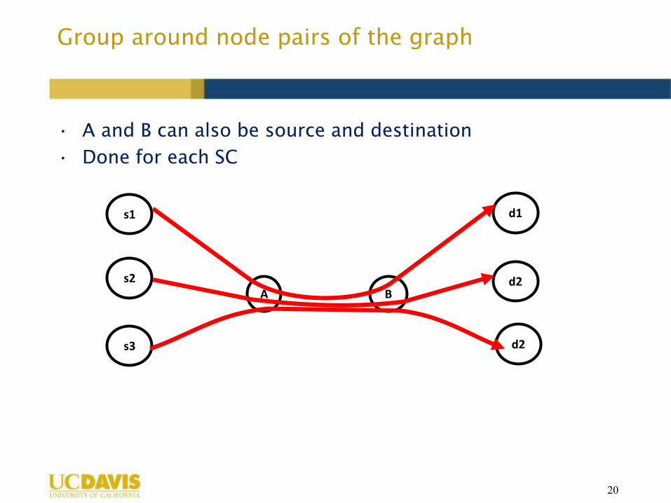
Group around node pairs of the graph
• A and B can also be source and destination
• Done for each SC
20
A B
s1
s2
s3
d1
d2
d2

Continued…
• Ordered node pair with highest traffic flow count passing
through on shortest paths
• Traffic flows which share sub-paths in common
• Deploying one SC instance for each such group
21

Shortest Path Traffic Grouping
(SPTG)
• Given: the number of instances for a SC, the traffic flows
for the SC
• The heuristic will:
1. Find the node pair with highest number of flows
2. This becomes another (s, d) pair group/cluster
3. All flows in group/cluster are removed from global flow list
4. Repeat step 1 to 3 until number of instances is reached
5. Iterate through the remaining flows:
1. Find best group based on which path length through node pair
2. Add flow to that group/cluster
22

Shortest Path Traffic Grouping
– Traffic Aware (SPTG-TA)
• Cluster around the heaviest/largest traffic flow
• The heuristic will:
1. Find the node pair with highest number of flows and the largest
flow
2. This becomes another (s, d) pair group/cluster
3. All flows in group/cluster are removed from global flow list
4. Repeat step 1 to 3 until number of instances is reached
5. Iterate through the remaining flows:
1. Find best group based on which path length through node pair
2. Add flow to that group/cluster
23

2 Phase Model
• 1st
phase
• Apply SPTG/SPTG-TA for each SC and create the required number of
groups
• Assign dummy SC ids to groups of flows
• 2nd
phase
• Use the column generation model which decides on 1 SC instance
per SC
• Also we can control the number of nodes that can host VNFs, we
refer to this number as ‘K’
24

Assumptions
• All nodes are capable of hosting VNFs
• No CPU constraints are enforced
• No link capacity constraints are enforced
• Only one SC instance per SC model
• All traffic pairs have 1Gb traffic flow
25

NSFNET K=14
26

NSFNET K=14,5,4,3,2,1
27

Partitioning of Traffic Load
28

Partitioning of CPU resources
29

VNF Replica Constraints
30

Correlation between ‘K’ and ‘VNF Replica Count’
31

Mean Maximum Link Load
32

Cluster Counts (Uniform Traffic – Same Load)
33

ASP Bandwidth Variation (Uniform Traffic – Same
Load)
34

Bandwidth Used (Uniform, Same Load, Across
Clusters and Traffic)
35

Continued…
36

Continued…
37

Compare Cluster Counts (Skewed Traffic – Same Load)
38

ASP Bandwidth Variation (Skewed Traffic – Same Load)
39

40
Bandwidth Used (Skewed, Same Load, Across
Clusters and Traffic)

Continued…
41

Continued…
42

Continued…
43

Scenario 2 (4 Service Chains, 1 Tb Load)
44
VNF 3 VNF 1 VNF 7 VNF 4 VNF 5
VNF 3 VNF 1 VNF 7 VNF 1 VNF 3
VNF 3
VNF 3
VNF 1
VNF 1
VNF 7
VNF 9
VNF 9
VNF 4
VNF 5
VNF 5
Web – 18.2%
VoIP – 11.8%
Video – 69.8%
Cloud Gaming - .2%

Continued…
45
VNF ID SC’s Traffic Load (Tbps)
3 0,1,2,3 1.118
1 0,1,2,3 1.118
7 0,1,2 .998
5 0,2,3 .882
4 0,3 .184
9 2,3 .700

K = 2
46
VNF ID SC’s Traffic Load (Tbps)
3 0,1,2,3 1.118
1 0,1,2,3 1.118
7 0,1,2 .998
5 0,2,3 .882
4 0,3 .184
9 2,3 .700

Continued…
47
VNF ID SC’s Traffic Load (Tbps)
3 0,1,2,3 1.118
1 0,1,2,3 1.118
7 0,1,2 .998
5 0,2,3 .882
4 0,3 .184
9 2,3 .700

K=3
48
VNF ID SC’s Traffic Load (Tbps)
3 0,1,2,3 1.118
1 0,1,2,3 1.118
7 0,1,2 .998
5 0,2,3 .882
4 0,3 .184
9 2,3 .700

K=4
49
VNF ID SC’s Traffic Load (Tbps)
3 0,1,2,3 1.118
1 0,1,2,3 1.118
7 0,1,2 .998
5 0,2,3 .882
4 0,3 .184
9 2,3 .700

K=5
50
VNF ID SC’s Traffic Load (Tbps)
3 0,1,2,3 1.118
1 0,1,2,3 1.118
7 0,1,2 .998
5 0,2,3 .882
4 0,3 .184
9 2,3 .700

K=14
51
VNF ID SC’s Traffic Load (Tbps)
3 0,1,2,3 1.118
1 0,1,2,3 1.118
7 0,1,2 .998
5 0,2,3 .882
4 0,3 .184
9 2,3 .700

Scalability of 2 Phase Model
52

Future Work Directions
• Cases where distribution of VNFs occur:
• Cases where CPU resources are constrained or VNF replicas (because
of licenses) are enforced
• Any additional cases?
53