department of the army technical manual · department of the army technical manual operator,...
TRANSCRIPT

TM 11-5985-284-15D E P A R T M E N T O F T H E A R M Y T E C H N I C A L M A N U A L
OPERATOR, ORGANIZATIONAL,
DS, GS, AND DEPOT MAINTENANCE
INCLUDING REPAIR PARTS
SPECIAL TOOLS LISTS
MANUAL
ANTENNA, LOOP AT-784/PRC( N S N 5 8 2 0 - 0 0 - 0 8 6 - 7 6 5 1 )
This copy is a reprint which includes current
p a g e s f r o m C h a n g e s 1 t h r o u g h 5 . T i t l ew a s c h a n g e d b y C h a n g e 5 .
H E A D Q U A R T E R S , D E P A R T M E N T O F T H E A R M Y
F E B R U A R Y 1 9 6 7

CONDENSED OPERATING INSTRUCTIONSCautioa: Use for reception oniy. Do not transmit.
Whenever loop antenna is not in use, keep ATTENUATORswitch set in O position. Choose operating location freefrom obstructions.
To Operate
u. From .Iiodtflutcd Carrier tli~(al Sowcc. The nuru-bers of steps 1 through 3 and 8 belo\v nre the same asthose on the illustration.
( 1 ) Swing loop antwma up from the case. Do notextend the whip.
(2) Connect imtennu cable from connettor jl (ofAT–10t32/PRC ) to the tintenna coaxial connectorof the receiver. Set r~eiver v{}iunle rontrol to
(3)(4)
(3)
{6)
muxirnurm and squelch off.Set the ATTEN[l.\TOR s!vitcb to positio]) 0.Set the BAN IMIWITCH to the desired frequencyband.Adjust FISE T[’SE (mntrf)l to fiesi!w! operatingfrequency within ~elf[twl 1,:11)(1.Hold 100IJ antw]na ut eye ievel ti]ltl rottite u]jtil
signal is received. Adjust FIXE TUNE (5) formaximum reeponee. If resporme is too fstrOUg,advance A!IY’ENUATOR (3) to htgher number.
( 7 ) Rotating the loop will obtain two Poait!on% 180”apart corresponding to SIGNAL NULL arrows,giving maximum signal response.
( fiJ Extend the whip and note signal reaponae in oneposition. Rotate the antenna one-haM turn( 160° ) and note response in second position.
(0) Orient the antenna to obtain stronger signal reslmuse. The SIGNAL MAX arrow (on thecase) now points toward the transmitter.
( 10) Retract the whip. Rotate the antenna one-quarter turn (60” ) to SIGNAL NULL positionfor sharp and accurate bearing Indication.
h From Unmodulated Carrier Signal 8our&. @era-
tion procedure for direction finding from tits source ithe same as tlescribsd above. However, the shlmal IW-s~mnw sought in stel)s 6 through 9 is maximum quietingaction of cnrrier over noise. NULL is defined as maxi-munl noise obtained.

*TM 11-5985-284-15
T E C H N I C A L M A N U A L H E A D Q U A R T E R SD E P A R T M E N T O F T H E A R M Y
N o . 1 1 - 5 9 8 5 - 2 8 4 - 1 5 W A S H I N G T O N, DC, 3 F e b r u a r y
C H A P T E R 1 .Section I.
II.
C H A P T E R 2 .Section I.
II.
II.
Operator’s, Organizational, Direct Supportr General Supportand Depot Maintenance Manual
ANTENNA, LOOP AT-784/PRC(NSN 5820-00-086-7651)
ParagraphINTRODUCTIONGeneralScope - - - - - - - - - - - - - - - - - - - - - - - - - - - - - - - - - - -- - - - - - - - - - - - - - - - - - - - - - - - - - - - - 1-1Indexes of publications - - - - - - - - - - - - - - - - - - - - - - - - - - - - - - - - - - - - - - - - - - - - - - - - - -1-2Forms and Records - - - - - - - - - - - - - - - - - - - - - - - - - - - - - - - - - - - - - - - - - - - - - - - - - 1-3Reporting of errors - - - - - - - - - - - - - - - - - - - - - - - - - - - - - - - - - - - - - - - - 1-3.2Reporting equipment improvement recommendations (EIR) - - - - - - - - - - - - - - - - - - - -- - - 1-3.3Destruction of Army electronics material - - - - - - - - - - - - - - - - - - - - - - - - - - - - - - - - - - - - - - 1-3.3Description and DataPurpose and use - - - - - - - - - - - - - - - - - - - - - - - - - - - - - - - - - - - - - - - - - - - - - - - - - - - - - - - - - - 1-4Technical characteristics - - - - - - - - - - - - - - - - - - - -- - - - - - - - - - - - - - - - - -- - - - - - - - - - - - 1 - 5Components of Antenna, Loop AT-784/PRC - - - - - - - - - - - - - - - - - - - - - - - - - - - - - - - - - - - 1-6Items comprising an operable Antenna Loop AT-784/PRC - - - - - - - - - - - - - - - - - - - - - 1-6.1Description of Antenna AT-1082/PRC - - - - - - - - - - - - - - - - - - - - - - - - - - - - - - - - - - - - - - - - - - 1-7Description of associated components - - - - - - - - - - - - - - - - - - - - - - - - - - - - - - - - - - - - - - - - - - 1-8Additional equipment required - - - - - - - - - - - - - - - - - - - - - - - - - - - - - - - - - - - - - - - - - - - - - - - - - 1-9INSTALLATION AND OPERATION INSTRUCTIONSService Upon Receipt of Antenna, Loop AT-784/PRCUnpacking - - - - - - - - - - - - - - - - - - - - - - - - - - - - - - - - - - - - - - - - - - - - - - - - - - - - - - - - - - - - - - 2-1Checking unpacked equipment - - - - - - - - - - - - - - - - - - - - - - - - - - - - - - - - - - - - - - - - - - - - - - - - - 2-2Installation - - - - - - - - - - - - - - - - - - - - - - - - - - - - - - - - - - - - - - - - - - - - - - - - - - - - - - - - - - - - - - - - - - - - 2-3Siting - - - - - - - - - - - - - - - - - - - - - - - - - - - - - - - - - - - - - - - - - - - - - - - - - - - - - - - - - - - -- 2-4Antenna ControlsControls and their uses - - - - - - - - - - - - - - - - - - - - - - - - - - - - - - - - - - - - - - - - - - - - - - - - - - 2-5Controls and antennas - - - - - - - - - - - - - - - - - - - - - - - - - - - - - - - - - - - - - - - - - - - - - - - - - - - - - - - - - 2-6Operation Under Usual ConditionsGeneral - - - - - - - - - - - - - - - - - - - - - - - - - - - - - - - - - - - - - - - - - - - - - -- - - - - - - - - - - - - - - - --- 2-7Operation - - - - -- - - - - - - - - - - - - - - - - - - - - - - - - - - - - - - - - - - - - - - - - - - - - - - - - - - - - - - - 2-8Operation Under Unusual ConditionsGeneral - - - - - - - - - - - - - - - - - - - - - - - - - - - - - - - - - - - - - - - - - - - - - - - - - - - - - -- - - - - - - - - -- 2-9Operation in arctic climates - -- - - - - - - - - - - - - - - - - - - - - - - - - - - - - - - - - - - - - - - - - - -- 2-10Operation in desert climates - - - - - - - - - - - - - - - - - - - - - - - - - - - - - - - - - - - - - - - - - - - - - - - - - - - 2-11OPERATOR’S AND ORGANIZATIONAL MAINTENANCE INSTRUCTIONSOperator’s MaintenanceScope of operator’s maintenance - - - - - - - - - - - - - - - - - - - - - - - - - - - - - - - - - - - - - 3-1Preventive maintenance - - - - - - - - - - - - - - - - - - - - - - - - - - - - - - - - - - - - - - - - - - - - - - - 3-2Preventive maintenance checks and service periods - - - - - - - - - - - - - - - - - - - - - - - - - - - - 3-3Daily preventive maintenance checks and services chart - - - - - - - - - - - - - - - - - - - - - - 3-4Weekly preventive maintenance checks and services chart -- - - - - - - - - - - - - - - - - - - 3-5Cleaning - - - - - - - - - - - - - - - - - - - - - - - - - - - - - - - - - - - - - - - - - - - - - - - - - - - - - - - - - - -- 3-6Organizational MaintenanceScope of organizational maintenance - - - - - - - - - - - - - - - - - - - - - - - - - - - - - - - - - 3-7Monthly preventive maintenance - - - - - - - - - - - - - - - -- - - - - - - - - - - - - - - - - - 3-8Monthly preventive maintenance checks and services charts - - - - - - - - - - - 3-9Touchup painting - - - - - - - - - - - - - - - - - - - - - - - - - - - - - - - - - - - - - - - - - - - - - - 3-10Replacement of parts - - - - - - - - - - - - - - - - - - - - - - - - - - - - - - - - - - - - - - - - - - 3-11
*This manual supersedes TM 11–5820-496-20P, 13 March 1964, and TM 11-5820-496-35P, 24 July 1963.
Change 4
1967
Page
1-11-11-11-11-1
1 41-41 41-41-51-51-5
2-12-12-12-2
2-42-4
2-52-6
2-72-72-7
3-13-13-13-23-43-4
3-43-43-53-53-5
i
III.
I V .
CHAPTER 3 .Sect ion I .

TM 11–5985–284-15
C H A P T E R 4 ,Section I.
Section II.
C H A P T E R 5 .Section I.
II.
C H A P T E R 6 .
C H A P T E R 7 .
Section I.
II.
A PPENDIX A .A PPENDIX B .
Section I.II.
A PPENDIX C .Section I.
II.III.IV.
ParagraphDIRECT SUPPORT MAINTENANCEFunctioning of EquipmentScope ------------------------------------------------------------------------------------------------------------------ 4-1Antennas ------------------------------------------------------------------------------------------------------------- 4-2Direction finder antennas --------------------------------------------------------------------------------- 4-3Antenna AT-1082/PRC ---------------------------------------------------------------------------------------- 4-4Direct Support Troubleshooting and RepairOrganization of troubleshooting ------------------------------------------------------------------------- 4-5Test equipment required ----------------------------------------------------------------------------------- 4-6Resistance measurements ------------------------------------------------------------------------------------ 4-7Troubleshooting chart ------------------------------------------------------------------------------------------ 4-8Repairs ---------------------------------------------------------------------------------------------------------------- 4-9Removal and replacement of chassis and components -------------------------------------- 4-10Replacement of loop antenna arms ------------------------------------------------------------------- 4-11GENERAL SUPPORT MAINTENANCERepair and AlinementRepair ------------------------------------------------------------------------------------------------------------------ 5-1Frequency range alinement procedures --------------------------------------------------------------- 5-2General Support Testing ProceduresGeneral ----------------------------------------------------------------------------------------------------------------- 5-3Test equipment required --------------------------------------------------------------------------------------- 5-4Test conditions ----------------------------------------------------------------------------------------------------- 5-5Physical tests and inspection -------------------------------------------------------------------------------- 5-6Frequency range test -------------------------------------------------------------------------------------------- 5-7Sensitivity, attenuation, null, and sense tests -------------------------------------------------------- 5-8DEPOT OVERHAUL STANDARDSScope ------------------------------------------------------------------------------------------------------------------- 6-1Depot overhaul standards ------------------------------------------------------------------------------- 6-2SHIPMENT AND LIMITED STORAGE AND DEMOLITION TO PREVENT
ENEMY USEShipment and Limited StorageDisassembly ------------------------------------------------------------------------------------------------------- 7-1Repacking for shipment or limited storage ----------------------------------------------------- 7-2Demolition of Materiel to Prevent Enemy UseAuthority for demolition -------------------------------------------------------------------------------------- 7-3Methods of destruction --------------------------------------------------------------------------------------- 7-4REFERENCES ------------------------------------------------------------------------------------------------------BASIC ISSUE ITEMS LISTIntroduction -----------------------------------------------------------------------------------------------------------Basic issue items list ------------------------------------------------------------------------------------------------MAINTENANCE ALLOCATIONIntroduction -----------------------------------------------------------------------------------------------------------Maintenance allocation chart -----------------------------------------------------------------------------------Tool and tast equipment requirements ------------------------------------------------------------------Remarks ----------------------------------------------------------------------------------------------------------------
Page
4-14-14-14-3
4-74-74-74-7
4-104-104-10
5-15-1
5-25-25-25-2
FoldoutFoldout
6-16-1
7-17-1
7-17–1A-1
B-1B-1
C-1C-3C-4C-5
ii Change 4

TM 11-5985-284-15
CHAPTER 1INTRODUCTION
Section I. GENERAL1-1. Scope
a. This manual describes the components ofAntenna, Loop AT-784/PRC (fig. 1-1), and coverstheir use, operator’s maintenance, organiza-tional maintenance, and basic functioning. Italso contains the repair functions for thisequipment which are to be accomplished bydirect support, general support (DS and GS) anddepot maintenance.
b. Throughout this manual, the term sensewhip antenna refers to the telescoping portion ofAntenna AT-1082/PRC and loop refers to theloop antenna in which the telescoping antennais mounted.
1-2. Indexes of Publicationsa. DA Pam 310-4. Refer to the latest issue of
DA Pam 310-4 to determine whether there arenew editions, changes, or additional publica-tions pertaining to the equipment.
b. DA Pam 310-7. Refer to DA Pam 310-7 todetermine whether there are modification workorders (MWO’s) pertaining to the equipment.
1-3. Maintenance Forms, Records, andReports
a. Reports of Maintenance and Unsatisfac-tory Equipment. Department of the Army formsand procedures used for equipment mainte-nance will be those prescribed by TM 38-750, TheArmy Maintenance Management System(TAMMS).
b. Report of Packaging and Handling De-ficiencies. Fill out and forward DD Form 6(Packaging Improvement Report) as prescribedin AR 700-58/NAVSUPINST 4030.29/AFR 71-13/MCO P4030.29A, and DLAR 4145.8.
c. Discrepancy in Shipment Report (DISREP)(SF 361). Fill out and forward Discrepancy inShipment Report (DISREP) (SF 361) as pre-scribed in AR 55-38/NAVSUPINST 4610.33B/AFR 75-18/MCO P4610.19C and DLAR 4500.15.
1-3.1. Reporting Errors and Recom-mending Improvements
You can help improve this manual. If you findany mistakes or if you know of a way to improvethe procedures, please let us know. Mail yourletter or DA Form 2028 (Recommended Changesto Publications and Blank Forms) direct to:Commander, US Army Communications andElectronics Materiel Readiness Command,ATTN: DRSEL-ME-MQ, Fort Monmouth, NJ07703.
1-3.2 Reporting Equipment ImprovementRecommendations (EIR)
If your Antenna, Loop AT-784/PRC needsimprovement, let us know. Send us an EIR. You,the user, are the only one who can tell us whatyou don’t like about your equipment. Let usknow why you don’t like the design. Tell us whya procedure is hard to perform. Put it on an SF368 (Quality Deficiency Report). Mail it toCommander, US Army Communications andElectronics Materiel Readiness Command,ATTN: DRSEL-ME-MQ, Fort Monmouth, NJ07703. We’ll send you a reply.
1-3.3. Destruction of Army ElectronicsMateriel
Destruction of Army electronics materiel toprevent enemy use shall be in accordance withTM 750-244-2.
1-1
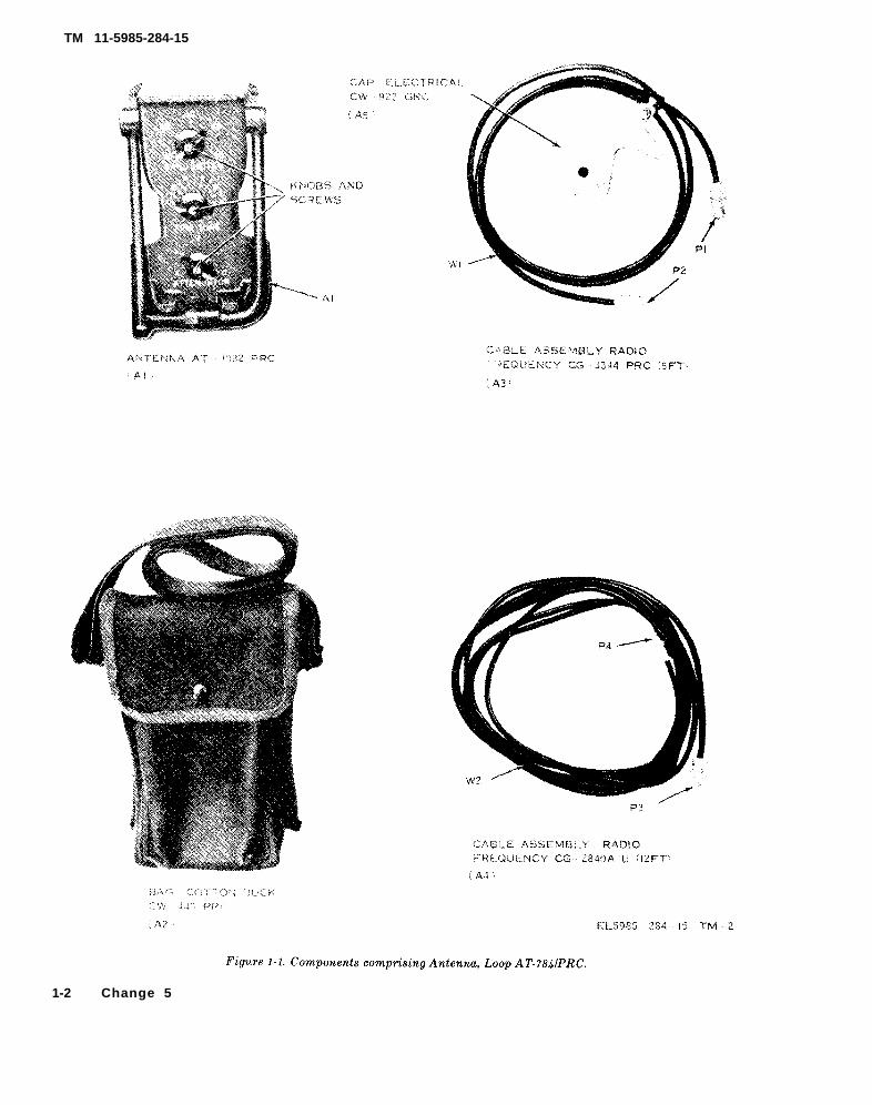
Figure 1-1.
TM 11-5985-284-15
1-2 Change 5

Figure 1-2.
TM 11-5985-284-15
Section Il. DESCRIPTION AND DATA
1-4. Purpose and Useu. Purpose. Antenna, Loop AT-784/PRC, when
used in conjunction with Radio Set AN/PRC-25,AN/VRG-12, or their equivalents, comprises ahoming device that enables the operator to findthe direction of a transmitted signal within thefrequency range of 30 to 76 MegaHertz (MHz).
CAUTIONUse the AT-784/PRC for reception only.Do not transmit. Whenever the loop
its extendable sense whip antenna (fig. 1-2) is
antenna is not in use, keep the AT-TENUATOR switch set to 0.
The unshielded loop antenna of Antenna AT-1082/PRC is used to pick up a homing signal, and
used to determine the direction of the transmit-ted signal. The AT-1082/PRC is not providedwith an azimuth indicator, since highly accu-rate bearings are not generally required for
homing purposes. A pocket compass can be usedto provide approximate azimuth readings bysighting in the direction of the indicated bear-ing.
1-5. Technical CharacteristicsFrequency range . . . . . . . ..30 to 76 MHz covered
in five bands.Frequency bands. . . . . . . ..(1) 3040 MHz.
(2) 40-50 MHz.(3) 50-60 MHz.(4) 60-70 MHz.(5) 70-76 MHz.
Fine tuningrange . . . . . . . . . . . . . . . . .. 0-10 MHz covered in
1-MHz steps.Signal attenua-
tion . . . . . . . . . . . . . . . . . . .. 0-46 dB covered infive step: 0, 10,20, 30, and 40 dB.
Change 5 1 -3

TM 11-5985-284-15
1-6. Components of Antenna, Loop AT-784/PRC(Fig. 1-1)
The components of Antenna, Loop AT-784/PRV,are listed in the following table:
Quantity
111
1
Item
Antenna AT-1082/PRCBag, Cotton Duck CW-445/PRCCable Assembly, Radio Frequency
CG-3344/PRC (5-ft).Cable Assembly, Radio Frequency
CG-2840A/U (12 ft).
Height(in.)
*’7½
8
Depth(in.)
Width Unit(in.) weight
(lb)
4¼ 2½
6 ¼ 0.9
“Refers to the height with the sense whip antenna retracted and the loop antenna turned down.
1-6.1. items Comprising an Operable Antenna, Loop AT/784/PRC
NSN
5820-00-086-7651
5985-00-889-39215995-00-933-98625985-00-937-16305995-00-933-8961
Quantity
1
1111
Nomenclature, part No., and mfr code
NOTEThe part number is followed by the applicable 5-digit Federalsupply code for manufacturers (FSCM) identified in SB 708-42and used to identify manufacturer, distributor, or Governmentagency, etc.
Antenna, Loop AT-784/PRCwhich includes:
Antenna AT-1082/PRC: MIL-A-55138, 80063Cable Assembly, RF, CG-3344/PRC: SM-D-5088884, 80063Cap, Electrical, CW-922/GRC: SC-DL-508885, 80063Cable Assembly RF, CG-2840 A/U: SM-D-508886, 80063
Fig. No.
1-1
1-11-11-11-1
1 - 4 Change 5

1-7. Description of Antenna AT-1082/PRC(fig. 1-2)
Antenna AT-1082/PRC is a compact, portableunit that is housed in a cast aluminum case. Aloop antenna is mounted on top of the caseand it has an expendable sense whip antennawithin its left side. The case is shaped to beeasily hand held land serves to protect theantenna assembly when it is folded down andto protect its panel controls from accidentaldamage by dropping. The grooved rear coverof this case allows access to the componentsand provides a watertight inclosure. An in-struction label that contains condensedoperating instructions (fig. 2-3) is secured tothe cover. The control sof the AT-1082/PRCinclude a bandswitch, a fine tuning control,and an attenuation control switch.
1-8. Description of Associated Components
The minor components of Antenna, LoopAT-784/PRC, which are associated with An-tenna AT-1082/PRC, are shown in figure 1-1and are described below:
a. Cable Assembly , Radio FrequencyCG-3344/PRC (5-Ft). This is a 5-foot cable in-
C 2, TM 11-5985-284-15
eluding Cap, Electrical CW-922/GRC (shieldcap), for the large antenna post of the as-sociated radio receiver, attached by cord. It isused to connect AT-1082/PRC to the as-sociated receiving set.
b. Cable Assembly, Radio FrequencyCG-2840 A/U (12-Ft). This is a 12-foot cablethat is provided for extending the cable con-nection of the AT-1082/PRC to a receiving setwhenever required.
c. Bag, Cotton Duck CW-445/PRC. This bagi s f o r c a r r y i n g a n d s t o r i n g A n t e n n aAT-1082/PRC, a shield cap for its output con-nector, and the two associated cables. Mois-ture and fungus resistant cotton duck mater-ial is used for the construction of this bag.
1-9. Additional Equipment Required
Radio Set AN/PRC-25, AN/VRC-12, or equi-valent, is not supplied with Antenna, LoopAT-784/PRC; however, one of similar type isrequired for use of this antenna. F o rexample: Radio Set AN/PRC-25, which is amanpack receiver-transmitter, is capable ofreceiving input signals over the frequencyrange of 30 to 76 MHz.
1 - 5


INSTALLATION
CHAPTER 2
AND OPERATION
C 2, TM 11-5985-284-15
INSTRUCTIONS
Section I. SERVICE UPON RECEIPT OF ANTENNA LOOK AT-784/PRC
2-1. Unpacking
a. Packaging Data. When packed for ship-ment, the components comprising Antenna,Loop AT-784/PRC, are placed in a corrugatedcardboard carton. A typical shipping cartonand its contents is shown in figure 2-1. Thedimensions of the carton are 10½ by 6½ by 5inches.
b. Removing Contents. To unpack, proceedas follows: Open the carton, lift out Bag, Cot-ton Duck CW-445/PRC, remove its contents,and check the components (para 2-2, and para1-6.1).
NOTE
Save the original packing carton. Itcan be used again when the equip-ment is repacked for storage orshipment.
2-2. Checking Unpacked Equipment
a. Inspect all equipment for damage possi-bly incurred during shipment. If the equip-ment has been damaged, report the damageon DD Form 6 (para 1-3b).
b. See that the equipment is complete aslisted on the packing slip, or paragraph 1-6.1.Report all discrepancies in accordance withAR 735-11-2. Shortage of a minor assembly orpart that does not affect proper functioning ofthe AT-1082/PRC should not prevent use ofthe equipment.
2-3. Installation
To install Antenna AT-1082/PRC, follow theprocedures in a through e below.
a. Remove the AT-1082/PRC from theCW-445/PRC (carrying bag).
Figure 2-1. Packaging of Antenna, Loop AT-784/PRC.
2-1

C2, TM 11-5985-284-15
b. Place the loop antenna into operatingposition as shown in figure 2-3.
c. Connect c o n n e c t o r J 1 of theAT-1082/PRC to the antenna coaxial connec-tor of the radio set with which it is to be usedby the CG-3344/PRC cable. The 12-foot cable( C G - 2 8 4 0 A / U ) m a y b e a d d e d t o t h eCG-3344/PRC to increase the interconnectioncable length, if required.
d. Remove all other antennas from theradio.
e. T h e shield cap attached to theCG-3344/PRC (fig. 1-1) is provided for usewith Receiver-Transmitters, Radio RT-505/PRC-25 (part of Radio Sets AN/PRC-25 andAN/VRC-53) and RT-841/PRC-77 (part o fRadio Set AN/PRC-77). On these receiver-transmitters, press the shield cap down as faras it will go over the whip antenna base. Theinside top of the shield cap should contact thetop of the whip antenna base on the radio and
ground it to the radio set chassis. When theradio set whip antenna base is not grounded,it interferes with homing signals.
2-4. Siting(fig. 2-2)
The best performance of Antenna AT-1082/PRC is obtained when it is used over an unob-structed line-of-sight path with a compatibleradio set. For this reason, the AT-1082/PRCshould be operated away from obstructionssuch as large buildings, bridges, steel struc-tures, and hills. These objects will block ordeflect the desired signal, thereby makinghoming difficult or impossible. Also, thisequipment should not be operated nearhigh-power or telephone lines. The best sitesfor desired directional looping are on hilltopsor over open, flat terrain. Figure 2-2 illus-trates typical good and poor locations forAT-1082/PRC operation.
2 - 2

TM 11-5985-284-15
Figure 2-2. Using AT-1082/PRC in good and bad operating areas.
2 - 3

Figure 2-3.
TM 11-5985-284-15
Section Il. ANTENNA CONTROLS
2-5. Controls and Their UsesAll operating controls of Antenna AT-1082/
PRC are listed in paragraph 2-6 and are Shownin figure 2-3. Care should be taken not to forcecontrols since damage to switch contacts mayresult.
2-6. Controls and Antennas
2 - 4

Control or antenna
Loop antenna - - - - - - -
Function
When extended, receives radio wavesfor transmission through the AT-1082/PRC to the associated receiver.When situated broadside to thetransmitted signal, the signal isattenuated (null condition); con-versely, when situated so that theedges of the loop face the trans-mitted signal, the signal is notattenuated.
Control or antenna
Sense whipantenna.
TM 11-5985-284-15
Function
When extended and in conjunctionwith the loop antenna having theopposite edge of the loop an-tenna facing the transmitted signal,de-termines (senses) the direc-tion from which the signal istransmitted.
Section Ill. OPERATION UNDER USUAL CONDITIONS
Caution 1: Use the AT-784/PRC for recep-tion only. Do not transmit when the AT-784/PRC is connected to the radio set; remove allother antennas from the radio set.
Caution 2: Keep the ATTENUATOR switchto O whenever the AT-1082/PRC is not in use.
2-7. Generala. Modulated and Unmodulated Carrier. Di-
rection finding of, or homing-in on, a transmittingstation is accomplished by detecting its modulatedor unmodulated carrier. Usually, it is better tohome-in on the unmodulated carrier signal than avoice or test tone; the test tone or voice is best usedwhen the transmitting signal is somewhat distantfrom the AT-1082/PRC. When the transmittingsite is nearby, with the carrier modulated or un-modulated, it is better to follow the carrier indica-tion rather than the modulation feature.
(1) Modulated carrier. Modulation of thetransmitter carrier frequency occurs whenvoice, music, test tone, etc., are trans-mitted.
(2) Unmodulated carrier. This action oc-curs when the transmitter is turned on butthe carrier frequency is not modulated byvoice, music, test tone, etc. On ampli-tude modulation transmission (am), thetransmitter is detected by the quieting ofthe noise when tile receiver is turned inthe area of the transmitter frequency.On frequency modulation (fm) trans-mission, the transmitter is detected by thelessening or stopping of the rushing noise
when the receiver is tuned to the area oftile transmitter frequency.
b. Maximum Signal. The terms maximumsignal and maximum are used to define the posi-tion of the loop antenna. when it is so oriented thatthe greatest signal response (maximum signal) isheard in the receiver. This occurs when the sensewhip antenna is extended for sensing (d below).At this time, a greater response is obtained on thereceiver when that edge of the loop antenna op-posite the edge in which the sense whip antennais mounted faces the transmitter. When the sensewhip antenna is retracted, signals of equal inten-sity are obtained from either edge of the loopantenna.
c. Null Signal. The terms null position a n dnull are used to define tile position in which theloop antenna is oriented when minimum or no sig-nal response is heard on the receiver. This occurswhen either broadside of the loop antenna is facingthe transmitting station. The two nulls are de-fined properly when the sense whip antenna is re-tracted. The null gives a sharper or more ac-curate indication than the maximum sense position(d below). Consider the loop antenna as an en-larged gun-sighting device; it is necessary to lookthrough the hole formed by the loop antenna to-ward the transmitting station. This will be thesame direction as the maximum signal from theedge of the loop antenna (d below). In the pres-ence of a strong signal, the null will be moreclearly defined and quite narrow; the rotation ofa few degrees will produce sharp variations inthe received signal. On a weaker signal, the width
2 -5

TM 11-5985-284-15
of the null may increase to 30° or 40O. The centerof the null (or area) is the correct bearing.
d. Sensing. Because there are two nulls, thenull indication does not provide sufficient informa-tion for the operator to determine whether thetransmitting source is in front of, or behind, theloop antenna. To find the actual direction of thetransmitting source, a null is detected, the sensewhip antenna is extended, and the loop antenna isturned sideways to the transmitting signal.When the signal is loudest in the receiver, theSIGNAL MAX arrow on the top of the case (fig.2-3) will point in the direction of (sense) thetransmitting signal.
e. Homing. Homing is the procedure of detect-ing a transmitting station and approaching it.The general procedure is as follows:
(1)(2)
(3)
(4)
Find the null.Determine the sense and take a bearingon the transmitting station as indicatedby the SIGNAL MAX arrow on the topof the case (fig. 2-3).When the direction of the transmittingstation is determined, the sense whip an-tenna is retracted, the loop antenna isturned broadside to the transmitting sta-tion, and the null indication is detected onthe receiver. If the null is particularlybroad, rotate the loop antenna back andforth a few times. Select the center ofthe null, and proceed on a line throughthe center of the null until the transmit-ting station is reached.As the transmitter is approached, succes-sive bearings can be taken with increasedaccuracy because of the narrowing nullarea which results from increased signalstrength.
f. Attenuation.
Caution: Whenever the loop antenna is notin use, keep the ATTENUATOR switch at 0.
(1)
2-6
Very strong signals may have a tendencyto obscure the null and sense indication.In general, such signals will be foundclose to the transmitter. If the hearingsare obscured and the transmitter cannotbe seen, advance the ATTENUATORswitch to position 1, 2, 3, or 4 to reducethe signal strength to the point, wherethe null becomes clear.
(2) Positions 1, 2, 3, and 4 provide increas-ing and marked differences in attenua-tion. The position of least attenuationthat permits sense and bearing determi-nation should be used. operation inATTENUATOR position 4 is not nor-mally used except in the immediate vicin-ity of the transmitting station (within100 to 200 yards depending on the ter-rain). An accurate sense indication willbe difficult, to obtain in this position, butthis condition should not present anyoperating difficulties since the general di-rection of travel has been previouslyestablished and the null bearing shouldbe sufficient for transmitter location.
2-8. Operation
The operating procedure of Antenna AT-1082/PRC for homing-in on a modulated or unmodu-lated carrier is described below. On the receiver,the greatest, signal response (maximum signal)for a modulated carrier is indicated by a loudaudio output ; for an unmodulated carrier, theindication is indicated by maximum receiverquieting.
a. Preliminary.(1) Check to see that the AT-1082/PRC is
(2)
connected to the receiver (para 2-3).Remove all other antennas from the re-ceiver. Set the ATTENUATOR con-trol to 0.On the receiver, tune to the operatingfrequency, set the volume control formaximum loudness, and set the squelchcontrol to off when there is such aprovision.
b. Procedure.(1) Unfold the loop antenna, and set the
(2)
BANDSWITCH and FINE TUNE con-trols to the positions that are closest tothe frequency setting on the receiver.For example, to tune to 45.80 MHz, setthe BANDSWITCH control to 40 andthe FINE TUNE control to 5.Hold the AT-1082/PRC vertically (fig.2-2), and rotate it clockwise and counter-clockwise for maximum signal indicationon the receiver. Readjust the FINE

fig. 2-2
(3)
(4:
TUNE control for a greater output sig-nal on the receiver. A maximum signalindication will be indicated by a loud (b)audio output on the receiver because ofa modulated carrier or by maximum re-ceiver quieting because of an unmodu-lated carrier.
Caution: Do not use the FINETUNE control setting as a standard indetermining the transmitter fre-quency.
Adjust the ATTENUATOR control forcomfortable audio output from the re-ceiver. At this point, the AT-1082/PRCloop antenna is oriented edgewise to thetransmitting source.To determine the direction of the signalsource, proceed as follows: (5)
(a) Rotate the loop antenna 90° to obtaina null indication on the receiver. Theloop antenna is now broadside to the (6)signal source and is indicated by theSIGNAL NULL arrows on the signal
2-9. General
TM 11-5985-284-15
direction label on top of the case(fig. 2-3).Extend the sense whip antenna. Thisaction will cause a signal output fromthe receiver. Starting with the broad-side position ( (a) above), listen for themaximum output signal while rotatingthe loop antenna clockwise and thencounterclockwise from the broadsideposition. Set the AT-1082/PRC tothe position that provides the strongestsignal indication in the receiver. Theloop antenna is again in line with thetransmitting signal source, and the sig-nal source is in the direction away fromthe sense whip antenna, as indicatedby the SIGNAL MAX arrow on thesignal direction label. (* See below.)
Retract the sense whip antenna, and,using the loop antenna, home-in on thesignal source with the null indication.Adjust the ATTENUATOR control fora comfortable listening level of the re-ceived signal.
Section IV. OPERATION UNDER UNUSUAL CONDITIONS
Operation of Antenna AT-1082/PRC may bedifficult in regions where extreme cold, heat, hu-midity and moisture, sand conditions, etc., pre-vail. In paragraphs 2-10 and 2-11, instructionsare given on procedures for minimizing the effectof unusual operating conditions.
2-10. Operation in Arctic Climates
Subzero temperatures and climatic conditionsassociated with cold weather affect the efficientoperation of this equipment. Instructions andprecautions for AT-1082/PRC operation undersuch adverse conditions are as follows:
a. Handle the equipment carefully.b. Keep the equipment warm and dry.c. Keep frost or ice from accumulating on the
loop frame; such accumulations will prevent theloop from being opened or closed and will preventthe sense whip antenna from being extended orretracted.
d. Moisture will condense on equipment thathas been exposed to the cold and is brought into awarm room; it will continue to do so until roomtemperature is reached. This condition alsoarises when equipment warms up during the dayafter exposure during a cold night. When theequipment has reached room temperature dry itthoroughly.
2-11. Operation in Desert Climates
The main problem when operating this equip-ment in desert areas is the large amount of sandor dust and dirt which enters its moving parts.Therefore, Antenna AT-1082/PRC should bestored in dust proof cent ainers when it is not inuse. When using this equipment, keep it as freefrom dust and sand as possible. Excessive accu-mulation of sand, dust, or dirt on the loop framewill prevent the sense whip antenna from beingextended or retracted as required.
C h a n g e 1 2 - 7


Paragraph 3-4 Paragraph 3-5
TM 11-5985-284-15
CHAPTER 3
OPERATOR’S AND ORGANIZATIONAL MAINTENANCE INSTRUCTIONS
Section I. OPERATOR’S MAINTENANCE
3-1. Scope of Operator’s Maintenance
The maintenance duties assigned to the operatorof Antenna, Loop AT-784/PRC, are listed below,together with references to the paragraphs cover-ing the specific maintenance functions. The dutiesassigned do not require tools or test equipment,but two radio sets (AN/PRC-25, or equivalent)are required for operational checkout: One fortransmitting purpose and one for receiving AT-1082/PRC outputs.
a. Preventive maintenance ( para 3-2).b. Preventive maintenance checks and service
periods (para 3-2).c. Daily preventive maintenance checks and
services chart (para 3-4).d. Weekly preventive maintenance checks and
services chart ( para 3-5).e. Cleaning ( para 3-6).
3-2. Preventive Maintenance
Preventive maintenance is the systematic care,servicing, and inspection of equipment to preventthe occurrence of trouble, to reduce downtime, andto make sure that, Antenna, Loop AT-784/PRC, isin a combat serviceable condition at all times.Because of moisture and fungus growth, the main-tenance of this antenna in tropical climates is moredifficult than under temperate climatic conditions.The high relative humidity causes condensationto form on the equipment; this is especially truewhen temperature of the equipment becomes lowerthan the surrounding air. To minimize this con-dition, keep this type of antenna sheltered and offthe ground as much as possible.
a. Systematic Care. The procedures given inparagraphs 3-4 through 3-6 cover routine careand cleaning essential to proper upkeep andoperation of the equipment.
b. Preventive Maintenance Checks and Services.The preventive maintenance checks and servicescharts (paras 3-4 and 3-5) outline functions to beperformed at specific intervals. These checks andservices are to maintain Army electronic equip-ment in a combat serviceable condition; that, is, ingood general (physical) condition and in goodoperating condition. To assist operators in main-taining combat serviceability, the charts indicatewhat to check, how to check, and what the normalconditions are; the References column lists theillustrations, paragraphs, or manuals that containdetailed repair or replacement. procedures. If thedefect cannot be remedied by the operator, highercategory maintenance or repair is required.Records and reports of these checks and servicesmust be made in accordance with the requirementsset forth in TM 38-750.
3-3. Preventive Maintenance Checks andService Periods
3 - 1

TM 11-5985-284-15
3-4. Daily Preventive
Sequence
10
11
3 - 2
Item to be inspected
AT-1082/PRC, sensewhip antenna.
AT-1082/PRC, loopantenna.
AT-1082/PRC, con-trols.
Cables . . . . . . . . . . . . .
Connections . . . .
Controls . . . . . . .
Antenna parts . . . . . . .
CG–3344/PRC (5-ft) . . .
CG-2840A/U (12-ft) . . . .
AT-1082/PRC
AT-1082/PRC. con-trols and antennas.
Maintenance Checks and Services Chart
Procedure
Inspect for bends and distortion - - - - - - - - - - - - - - - - - - - - - - - - - - - - - - -
Check to see that loop antenna, opens to operating position with-out, binding.
Observe effect on signal during operating procedures . . . . . . . . . . .
a.b.
Inspect for damaged connectors. . . . . . . . . . . . . . . . . . . . . . . . . . .Check for tight connections . . . . . . . . . . . . . . . . . . . . . . . . . . . . . . . .
All antenna and cable connections should be fingertight. Checkand tighten when necessary.
Check to see that the mechanical action of each control is smoothand free of external or internal binding.
a.
b.
c.
d.a.
b.c.
a.
b.c.
a.
b.
c.
Check to see that the loop antenna can be easily placed into itsoperating position and that it locks in its detented position.
Check to see that the sense whip antenna can be extended itsfull height (12 inches) and remain there.
Check to see that the sense whip antenna and loop antenna maybe returned, respectively, to their nonactive positions
Check to see that the shield cap is attached to the CG-3344/PRC.Connect the cable to the radio receiver and the AT-1082/PRC;
if applicable, attach the shield cap to the radio antenna con-nector.
Check the connections for tightness - - - - - - - - - - - - - - - - - - - - - - - -Check the shield cap for snug fit on the antenna connector of the
radio and for connection to the CG–3344/PRC.Connect the CG-2840A/U between the CG-3344/PRC and the
radio receiver.Check the connections for tightness - - - - - - - - - - - - - - - - - - - - - - - - - - - - Continue to the operational checks - - - - - - - - - - - - - - - - - - - - - - - - - - - - - - -
Make all transmission and reception arrangements with a dis-tant radio transmitter before connecting the AT-1082/PRCto the receivcr. Note the direction of the transmitter.Arrange with the distant transmitting station to turn on itstransmitter long enough to make the AT-1082/PRC tests.
TO start the test, set the transmit and receive frequency to 30MHz. If the tactical situation will not permit this arrange-ment, use the assigned operating frequency.
Caution: Do not transmit from the radio set connected to theAT-1082/PRC; damage to the equipment may result.On the receive radio set, make the following adjustments:
(1) Set the volume control for maximum signal output.(2) set the squelch control, if provided, to off.
a.
b.
Set ATTENUATOR to 0; BANDSWITCH to 30 (or to positioncorresponding to assigned operating frequency); and FINETUNE to 0 (or to position corresponding to assigned operatingfrequency);
Set the loop antenna in operating position and extend the sensewhip antenna.
References
Sequence num-bers 5 through20 below.
a. None.b. Sequence
numbers 7and 8below.
Para 2-3.
Fig. 2-3, para2-6.
a. Fig. 2-3.
b. Same as aabove.
c. Same as aabove.
d. Fig. 1-1.a. Para 2-3, fig.
1-1.
b. None.c. Same as a
above.a. Fig. 1-1.
b. None.c. Sequence
numbers 11through 20below.
Para 2-6 andsequence No.10 above.

TM 11-5985-284-15
12
13
14
15
16
17
18
19
20
Item to be inspected
AT-1082/PRC - - - - - -
AT-1082/PRC,ATTENUATORcontrol.
AT-1082/PRC, FINETUNE control.
AT-1082/PRC,BANDSWITCHcontrol.
AT-1082/PRC, nullposition.
AT-1082/PRC,BANDSWITCH andFINE TUNE con-trols (45 MHz).
AT-1082/PRC,BANDSWITCH andFINE TUNE con-trols (55 MHz).
AT-1082/PRC,BANDSWITCH andFINE TUNE con-trols (6.5 MHz).
AT-1082/PRC,BANDSWITCHand FINE TUNEcontrols (75 MHz).
Procedure
a.
b.
c.a.
b.
a.
b.a.
b.a.
b.
a.h.c.
a.b.c.
a.b.
c.
a.b.c.
—
Position the loop antenna so that the SIGNAL MAX arrow onthe signal direction label is toward the transmitting station.Note the level of the received signal.
Rotate the loop antenna 180°. The received signal should belower.
Set the loop antenna in the original position (a above).Turn ATTENUATOR control to positions 1, 2, 3, and 4. At
each position, signal level should be lower.
Set the ATTENUATOR control for a comfortable listening levelon receiver.
Rotate the FINE TUNE control to each of its other positions.Received signal level should be lower as control is moved awayfrom the original setting.
Reset the FINE TUNE control to original position.Rotate the BANDSWITCH control to each of its other posi-
tions; no signal is received on the receiver in the other positions.Reset to the original position.Retract the sense whip antenna.
Rotate the loop antenna 90°; it is now broadside to the trans-mitting station. The received signal level should lessen orthe signal should disappear.
Note. If the tactical situation permits use of other frequencies, use the pro-cedures given in sequence numbers 17 through 20 below, to test the operation ofthe AT-1082/PRC in 40-, 50-, 60-, and 70-MHz bands, and disconnect the AT-1082/PRC from the radio receiver. Communicate with the distant radio stationand arrange for it to transmit using 45, 55, 65, and 75 MHz, in turn, while makingthe tasts given in sequence numbers 17 through 20 below which are associated witheach frequency.
Set BANDSWITCH to 40 and FINE TUNE to 5,Tune receiver to 45 MHz.Repeat procedures given in sequence lumbers 14 through 16
above.Set BANDSWITCH to 50 and FINE TUNE to 5.Tune receiver to 55 MHZ.Repeat procedures given in sequence numbers 14 through 16
above.Set BANDSWITCH to 60 and FINE TUNE to 5.Tune receiver to 65 MHz.
References
Fig. 2-3, para2-7d.
Repeat procedures given in sequence numbers 14 through 16above.
Set BANDSWITCH to 70 and FINE TUNE to 5.Tune receiver to 7.5 MHz.Repeat procedures given in sequence numbcrs 14 through 16
above.
—
3 -3

TM 11-5985-284-15
3-5. Weekly Preventive Maintenance Checks this chart lists the illustrations, paragraphs, or
and Services Chart manuals that contain detailed repair or replace-
The preventive maintenance checks and servicesment instructions to be followed while performing
of Antenna AT-1082/PRC that are listed belowthe procedure.
are required weekly. The References column of
SequenceNo.
1
Item to be inspected
Completeness
Procedure
Inspect for completeness of –a. Publications (check to See that they are complete, serviceable,
and current).b. Components . . . . . . . . . . . . . .
Clean the AT–-1082/PRC, extended sense whip antenna, cables,and CW-445/PRC.
Inspect cables for cuts, broken insulation and looseness of con-nectors on cable.
Check for connection to CG-3344/PRC . . . . . . .
3-6. CleaningInspect the exterior surfaces of Antenna, Loop
AT-784/PRC, including the exterior of its sensewhip antenna. All exterior surfaces should beclean and free of dirt, grease, and fungus.
a. Remove dust and loose dirt with a clean, softcloth.
Warning: Prolonged breathing of cleaningcompound is dangerous; make certain that ade-quate ventilation is provided. Cleaning com-pound is flammable; do not use near a flame.
References
a. DA Pam 310-4.
b. Fig. 1-1,app. B.
Para 3-6.
Fig. 1-1
Avoid contact with the skin; wash off any thatspills on your hands.
b. Remove grease, fungus, rust, and ground-indirt from the surfaces using a cloth dampened(not wet) with cleaning compound (FSN 7930-395-9542).
c. Remove dust or dirt from the connector witha brush.
d. Clean the control knobs: use a soft, cleancloth. If dirt is difficult to remove, dampen thecloth with water; mild soap may be used for moreeffective cleaning.
Section Il. ORGANIZATIONAL MAINTENANCE
3-7. Scope of Organizational MaintenanceThis section contains instructions covering orga-
nizational maintenance of Antenna AT-1082/PRC. The duties of an organizational repairmanare limited to the responsibilities listed below inaddition to those performed by the operator (para3-2 through 3-6).
a. Monthly preventive maintenance (para 3-8).b. Monthly preventive maintenance checks and
services (para 3-9).c. Touchup painting (para 3-10).d. Replacement of parts (para 3-11).
3-8. Monthly Preventive Maintenance
Perform the maintenance functions indicated in
the monthly preventive maintenance checks andservices chart (para 3-9) once each month. Amonth is defined as approximately 30 calendardays of 8-hour-per-day operation. If the equip-ment is operated 16 hours a day, the monthlypreventive maintenance checks and services shouldbe performed at 15-day intervals. Adjustments ofthe maintenance interval must be made to compen-sate for any unusual operating conditions.Equipment maintained in a standby (ready forimmediate operation) condition must havemonthly preventive maintenance checks and serv-ices performed on it. Equipment in limited stor-age (requires service before operation) does notrequire monthly preventive maintenance.
3 - 4

TM 11-5985-284-15
3-9. Monthly Preventive Maintenance Checks and Services Chart
1
2
345
Item to be inspected
AT-1082/PRC, ex-terior surfaces.
Cover assemblygasket.
Screws - - - - - - - - - - - - - - - -Sense whip antenna - - - -CW-445/PRC . . . . . . .
Procedure References
Repaint if necessary - - - - - - - - - - - - - - - - - - - - - - - - - - - - - - - - - - - - - - - - - Para 3-10.
a. Put small amount of silicone grease on its surface - - - - - - - - - - - a. Fig. 2-3,para 3-11a.
b. Replace lf necessary - - - - - - - - - - - - - - - - - - - - - - - - - - - - - b. Para 3-11a.Tighten screws holding knobs of controls and cover assembly - - - - - - -Replace if it does not retract fully, is bent, or comes free - - - - - - - - - - Para 3-11b.Inspect for tears, mildew, fraying, and attachment to strap - - - - - - - - Fig. 1-1.
3-10. Touchup Paintinga. When the finish on the case has been badly
scarred or damaged, rust and corrosion can beprevented by touching up the bared surfaces. UseNo. 000 sandpaper to clean the surface down to thebare metal and to obtain a smooth finish.
Caution: Do not use steel wool. Minute par-ticles may enter the case and cause harmfulinternal shorting or grounding of the circuit.
b. When a touchup job is necesary, apply paintwith a small brush. Remove rust from the caseby cleaning corroded metal with cleaning com-pound. In severe cases, it may be necessary to usecleaning compound to soften the rust, and sand-paper to complete the preparation for painting.Paint used will be authorized and consistent withexisting regulations (TB SIG 364).
3-11. Replacement of Parts(fig. 2-3)
For parts replacement, prepare a clean, flat worksurface for the unit. Thoroughly wipe off dirt,grease etc., particularly if found between thecover and the case. Use an airhose, if necessary.
a. Cover and/or Cover Assembly Gasket. Toreplace the cover and/or the cover assembly gas-ket, proceed as instructed below. (For lubrica-tion only, omit the procedures given in (2) and(3) below:)
(1) Loosen the six captive screws that holdthe cover assembly, and remove the coverassembly from the case.
(2) Pull the gasket from the cover.
Caution: Do not stretch the gasketby pulling it from one point to anotherduring its installation.
(3)
(4)
(5)
Lay the new gasket over its track on thecover and press it into place.With the fingers, spread a thin coating ofsilicone grease on the surface of thegasket.Place the cover on the case, making surethat the gasket is seated properly, andtighten the cover down with its six cap-tive screws.
b. Sense Whip Antenna. TO replace a whip an-tenna in the loop antenna assembly, proceed asfollows:
(1)
(2)
(3)
Set the loop antenna (3, fig. 4-6), in op-erating posit ion.Hold the loop antenna and loosen thewhip antenna assembly nut (22) with ahexagonal wrench. Completely unscrewthe nut, and remove the telescoping whipantenna (21 ).Apply a thin layer of silicone grease tothe threads on the assembly nut of thesense whip antenna to be mounted. Par-tially place the assembly into position onthe loop antenna. Extend the sense whipantenna from its assembly, and screwthe assembly nut in place by band; then,tighten the nut with the hexagonalwrench.
c. Control Knobs. Use the following procedurefor replacement of the 13 BANDSWITCH, FINETUNE,
(1)
(2)
and the ATTENUATOR control knobs.Note the position of the control knob(for example: BANDSWITCH set to30).Remove the screw that, holds the controlknob in position.
3 - 5

TM 11-5985-284-15
(3) Lift and remove the control knob from (5) Mount the new control knob on the shaftthe associated shaft. so that it is set in the same position as the
(4) Clean the shaft and the case surface from knob which was removed ((1) above).which the control knob was removed. (6) Hold the control knob in position, and
tighten down its retaining screw.
3 - 6

Figure 4-1.
TM 11-5985-284-15
CHAPTER 4
DIRECT SUPPORT MAINTENANCE
Section I. FUNCTIONING OF EQUIPMENT
4-1. ScopeThis chapter contains instructions for direct
support maintenance of Antenna AT-1082/PRC.It includes instructions appropriate for trouble-shooting, testing, alining, repairing the equipmentand replacing maintenance parts by repairmen atthis maintenance category. It also lists the as-sociated tools, materials, and test equipments. De-tailed functions of the AT-1082/PRC are coveredin paragraphs 4-2 through 4-4.
4-2. Antennasa. General. During transmission, a radiofre-
quency (RF) current in a conductor produces anelectromagnetic field that is radiated into space.This field consists of electric and magnetic fieldsthat are at right angles to each other. The planeparallel to the mutually perpendicular lines ofelectric and magnetic flux is called the wavefront.The wave travels in a direction at right angles tothe wavefront.
b. Receiving Antennas.
(1)
(2)
If the radiated electromagnetic field cutsa conductor, current is induced into thatconductor. The received current variesin accordance with the variations of theelectromagnetic field. Therefore, a vari-ation of the current in a radiating an-tenna causes a similar varying current ina conductor at a distant location.Antennas receive more energy in somepositions than they do in others. Thisdirectivity is due to the fact that receivedenergy depends on the amount of radiatedfield that is cut by the antenna. A hori-zontal antenna receives maximum energywhen its vertical plane is parallel to theplane of the wavefront because maximuminterception occurs in this position. Avertical antenna has the same receptionstrength from all horizontal directionsbecause the amount of radio field that it
intercepts remains constant. Typicalfield strength patterns for vertical andhorizontal antennas are illustrated in Aand B, figure 4-1.
4-3. Direction Finder Antennasa. General. Since fundamental half-wave an-
tennas possess directional characteristics, it is pos-sible to determine the direction from which a radiosignal is being received. This determination ismade by rotating the receiving antenna about anaxis that is perpendicular to the direction of thesignal and observing the changes in received sig-nal strength. However, as can be seen from theradiation pattern in A, figure 4-1, the directional
4-1

figure 8
fig 4-1
figure 4-2
figure 4-2
figure 4-2
figure 4-2
fig. 4-2
fig. 4-2
fig. 4-3
figure 4-3
figure 4-3
figure 4-3
figure 4-3
figure 4-3
TM 11-5985-284-15
4 -2

Figure 4-2.
4-4.
fig. 4-4
4-3
TM 11-5985-284-15

4-4
TM 5985-284-15-9
Figure 4-3.4-4
TM 11-5985-284-15

Figure 4-4.
4-5
TM
11-5985-284-15

TM 11-5985-284-15
of resistors R1 through R9 on subassembly A3.The amount of attenuation is selected by AT-TENUATOR switch A3S1 in four steps. Eachof the first three steps provides approximately 10decibels (db) of attenuation, and the fourth stepprovides aproximately 6 db of attenuation. The() position of switch A3S1 couples a tap of L1directly to RF output connector J1. This antennahas an output impedance of approximately 50ohms.
e. As shown in C, figure 4-1, the pattern of asimple loop passes two identical nulls and twoidentical maximum points, 180° apart. The pat-term leaves 180° uncertainty as to the direction ofthe transmitter regardless of which technique(maximum pjoints or nulls) is used to find the di-rection. Since the transmitter may be either infront of or behind the loop, another element is usedto eliminate one direction. The sense of the bear-ing can be determined by introducing a small volt-age derived upon raising the vertical sense whipantenna. This sense whip antenna is a simplevertical whip antenna, 12 inches long, whose outputis mixed with that of the loop. The sense whipantenna current, caused by electric field activity,combines with the loop circuit current in trans-former L1. The vector addition of these currentsproduces the desired cardiod response (pattern D,fig. 4-1).
f. Superimposing the circular sense pattern overthe loop pattern (since they occur at the same in-stant) provides the loop plus sense cardiod patternin D, figure 4-1. In D, figure 4-3, the vectors showthe loop aimed at the transmitting station. Thedotted arrow represents the current in any direc-tion, while the arrow composed of triangles repre-sents the current flow within the loop (as shown inC, fig. 4-2) with the loop aimed at the station.Since both of these currents circulate in the same
direction, they add together and provide a markedincrease in output signal to point the way to thestation. In E, figure 4-3, the vectors show the loopaimed away from the transmitting station. Thedotted arrow is the same current, while the arrowcomposed of triangles is the loop output current(as shown in D, fig. 4-2) with the loop away fromthe station. Since these current components op-pose each other, very little output is obtained, prov-ing this is not the true direction to the station. Bysimilarly summing up the circular sense patternand the figure 8 loop pattern in all directions, thecardiod pattern is obtained.
g. While the sensing definitely points the direc-tion to the transmitter, the broadness of the lobemakes it difficult to spot the bearing sharplyenough. Using the null to sharpen the bearing andfollowing the null to the station (para 2-7e) arestandard direction finding practices. If theoperator loses his bearings and has difficulty in re-locating the general direction of the transmitter,the sense operation should be repeated.
h. The sensing current must be equal to, orslightly less than, the net loop current. If thesense current is too small, a pattern consisting ofone large lobe, one small lobe, and two nulls lessthan 180° apart is produced. If the sense currentis too high, it will mask the loop characteristicsand produce a pattern with an indistinct maximumand minimum.
i. For proper operation of Antenna AT-1082/PRC, the signal output (applied to the ]imiter ofa receiver) should be of such an amp] itude as toappear on the slope of the limiter curve. To ac-complish this, the step attenuator circuitry of AT-1082/PRC, which consists of a ladder-type pi-net-work of resistors, may be used as required (dabove). Tile amount of attenuation dependsupon the position of the ATTENUATOR switch(fig. 4-4).
4 - 6 C h a n g e 1

4-5.
4-6.
4-7.
4-8.
para 4-8
figure 4-5
para 3-4b
paragraph 3-4b
paragraph 4-8
TM 11-5527
T M 1 1 - 5 9 8 5 - 2 8 4 - 1 5
Section Il. DIRECT SUPPORT TROUBLESHOOTING AND REPAIR
4 - 7

4-8
TM 11-5985-284-15
Item
1
2
3
4
5
Indication
No output signal suppliedto associated receiver.
No output during 30-MHzoperation.
No output during 40-MHz operation.
No output during 50-,60-, or 70-MHz opera-tion.
Rotation of FINE TUNEcontrol C1 causes noisein receiver.
Probable trouble
a. Shortcd or open coaxial cable - - - - - - - - -
b. Defective ATTENUATOR switch.
c. Defective attenuation pi-network cir-cuit.
Defectivc BANDSWITCH switch (A2S1).
a. Defective switch A2S1 - - - - - - - - - - -
b. Inductor A2L4 open or A2C4 shorted . . .
Defective inductor and/or capacitor onassembly A2 : L3 or C3 for 50-MHzoperation, L2 or C2 for 60-MHz opera-tion, L1 or C1 for 70-MHz operation.
Capacitor C1 plates bent (rub againsteach other), or shaft bearing is noisy.
Procedure
a. Make resistauce check of cable; ifshorted, replace cable.
b. Clean and check continuity of switchA3S1 ; if defective, replace asseblyA3.
Note. Assembly A3 includes switch and resis-tors (fig. 4-4).
c. Check resistors R1 through R9 onassembly A3 ; if any resistor is defec-tive, replace assembly
Clean and make continuity check of A2S1if switch is defective, replace assembly
A 2 .Note. Assembly A2 includes switch and circuit
components (fig. 4-4).
a. Check continuity of A2S1; if defective,replace assembly A2.
b. Make resistance check of A2 L4 andA2C4. If defective, replace assembly
Make resistance check of associated in-ductor and capacitor. If defective,replace assembly A2.
Repair bent plates. If capacitor isdefective, higher category repair is re-quired. (Alinement of circuit is re-quired if C1 is replaced.)
Change 1

TM 11-5985-284-15
Figure 4-5. Antenna AT-1082/PRC (assembly A1), interior view.
4 - 9

TM 11-5985-284-15
4-9. Repairs
Most of the parts in Antenna AT-1082/PRC canbe reached easily without special procedures. Therepair duties of a direct support maintenance re-pairman are limited to the repair procedures listedbelow.
a. Removal and replacement of A1 chassis andcomponents (para 4-10) .
b. Removal and replacement of loop antennaarms (para 4-11).
Caution: Be careful when handling inductorsand rotor assemblies. Do not bend these parts.
4-10. Removal and Replacement of Chassis
and Components
a. Removal (figs. 4-5 and 4-6).(1)
(2)
(3)
(4)
(5)(6)
Remove the six captive cover screws hold-ing the cover to the case.Loosen the three retaining screws on thethree knobs; remove the knobs.Unsolder the wire from connector J1 tothe ATTENUATOR switch.Remove the three hex nuts holding thecontrol shafts in position.Lift the chassis up and out of the case.For the removal of switch assembly A1S1or A2S1, capacitor C1, or connector J1,
unsolder the connections, unscrew the as-sociated shaft nut, and lift the releaseditem up from the chassis.
b. Replacement.(1) Mount connector J1 to the case, and solder
(6)
(7)
4-10
its ground connection.Mount the switch assembly (A1S1 and/orA2S1) and capacitor C1 on the chassis,and screw on the associated shaft nut.Place the chassis back in the case, andtighten the three hex nuts on the controlshafts of A1S1, A2S1, and C1. Then,attach the switch knobs.Install the six mounting screws for hold-ing tile chassis to the case.Solder the connections of the replaceditems, and solder in capacitors C2 and C3,if required.Solder the wire from ATTENUATORswitch A2S1 connector to J1.Place the cover on the case, making surethat the rubber gasket is seated properly,
and tighten the cover down with the sixcaptive screws.
4-11. Replacement of Loop Antenna ArmsTo replace loop antenna arms, follow the pro-
cedures outlined in a and b below. For item num-bers given in a and b below, refer to figure 4-6.
a. Removal. For removal of the loop antennaleft side only (antenna coaxial arm assembly, item4), omit the procedures in (5) below. All proce-dures listed are required for removal of both loopantenna sides (items 3 and 4). Item 3 (antennaarm assembly) is the loop antenna right side.
(1)
(2)
(3)
(4)
(5)
(6)
(7)
If possible, set the loop antenna into itsoperating position.Unscrew the six cover screws, and re-move the cover (1) from the case (2).On the side of the loop antenna to beremoved, antenna arm assembly (3) and/or antenna coaxial arm assembly (4), pullthe E-ring (5) from its mounting.Unscrew the coupling cap (6), and slideit to the sense whip antenna as far aspossible.For removal of antenna coaxial arm as-sembly (4), remove the leaf springs (7and 8) that are mounted on the case.Unsolder the tinned copper wire (9)from the contact plug (10). When heat-ing contact plug (10), hold the solderingiron there and push the top portion ofthe antenna arm assembly (3 or 4) to beremoved while having an assistant repair-man press the contact point of that assem-bly from the case (2).
Caution: Once the tinned copperwire (9) has been removed from thecontact plug (10), remove the solder-ing iron. This will prevent damage toeither antenna arm assembly side (3or 4) of the loop antenna.
After the desired antenna arm assembly(3 or 4) has been dismounted, removeO-rings (11) and spring washer (12) asrequired. If antenna coaxial arm assem-bly (4) has been dismounted, remove thenut from the contact plug (10), lock-washer (13), cent act plug (10), capbearing (14), and coupling cap (6), asrequired.

b. Replacement. For replacement of the an-tenna arm assembly (3) only, omit the proceduresgiven in a(1), (4), and (8) below. All proceduresare required for the replacement of a completeloop antenna.
(1)
(2)
(3)
(4)
For antenna coaxial arm assembly (4)replacement, apply glyptal compound (orequivalent ) to the threads of the contactplug (10), screw the contact plug (10)in place on antenna coaxial arm assembly(4), slide on the coupling cap (6), insertthe cap bearing (14) over the contact plug(10) into the coupling cap (6), place thelockwasher (13) on the contact plug (10),and screw on the nut for the contact plug(10).For antenna arm assembly (3 or 4) re-placement, apply a layer of silicone greaseto the arm assembly surface which willmeet the spring washer (12). Mount thespring washer (12) with the O-rings (11).Set the case (2), with its cover (1) re-moved, in place for loop antenna mount-ing. (If either antenna arm assembly(3 or 4) has not been removed, raise thatassembly to its operating position. )Cover the replaced O-rings (11) with athin layer of silicone grease, and set theantenna arm assembly (3 or 4) in its oper-ating position for mounting.Insert the antenna arm assembly of one
(5)
(6)
(7)
(8)
(9)
TM 11-5985-284-15
loop antenna side (3 or 4) into its mount-ing hole on proper side of the case (2).Insert the base of that arm assembly (3or 4) slightly into its associated mountinghole on the case (2), and check the aline-ment of the contact plug (10) with thetinned copper wire (9) which is containedin antenna arm assembly (3).With the tinned copper wire (9) and thecent act plug (10) in alinement, press theantenna arm assembly (3 or 4) that isbeing mounted, into the case (2).Solder the tinned copper wire (9) andthe contact plug (10). Slide the cou-pling cap (6) into position, and screw itto the other antenna arm assembly (4).For the antenna coaxial arm assembly(4), insert E-ring (5) in place on the bot-tom of its antenna arm assembly. Placeleaf springs (8) and (7) in position, andsecure them to the case (2).For the antenna arm assembly (3), insertE-ring (5) in place on the bottom of itsantenna arm assembly.
(10) Turn the case (2) over, and check to besure that the loop antenna can be lockedin its detented position and easily placedin its operating position.
(11) Place the cover (1) on the case (2),making sure that the rubber gasket isseated properly, and tighten the coverdown with the six captive screws.
(1)
4 - 1 1

TM
11-5985-284-15F
igure 4-6. Antenna A
T-1082/P
RC
(assembly A
1), location of removable parts.
4-12

TM 11-5985-284-15
Figure 4-7. Antenna AT-1082/PRC, (assembly A1), front panel parts.
4-13


para 5-2 para 5-7
para 5-7
TM 11-5985-284-15
CHAPTER 5
GENERAL SUPPORT MAINTENANCE
Section I. REPAIR AND ALINEMENT
5-1. Repair
a. Maintenance of Antenna. AT-1082/PRC atgeneral support level consists of replacing com-ponents on assemblies A2 and A3, performing thefrequency range alinement (para 5-2), and per-forming the general support testing procedures(paras 5-3 through 5-8).
b. BANDSWITCH assembly A2 and ATTEN-UATOR switch assembly A3 each containing itsswitch and components (figs. 4-4 and 4-5), can bereplaced or the assembly components can be re-placed. Refer to paragraph 4-10 for removal andreplacement procedures for the switch assemblies.To replace defective components on either switchasembly, unsolder the defective components and
5-2. Frequency Range Alinement Procedures
a. General. The frequency range alinementprocedures given in b below are performed whencomponents of BANDSWITCH assembly(figs. 4-4 and 4-5) are replaced and when theperformance standard given in the frequencyrange tests (para 5-7) is not within limits. The30- and 39-MHz test frequencies are used as thetest frequencies; other frequencies used in the op-eration of the AT-1082/PRC should pass throughsatisfactorily.
b. Procedure.
(1) Perform the operations given in stepNo. 1, paragraph 5-7.
(2) When the procedures given in step No. 1,paragraph 5-7 are completed, set the AT-1082/PRC controls as follows:
(a) ATTENUATOR: 0.(b) FINE TUNE :0.(c) BANDSWITCH :30.
install their replacements..(1) After an inductor or capacitor on BAND-
SWITCH assembly A2 has been replaced,perform the alinement procedures givenin paragraph 5-2 and then the perform-ance procedure given in the chart belowassociated with the replaced component.
A2 Component Performance procedure
Adjust the slug in coil L1 (fig. 4-5) toobtain a reading of 30 MHz on frequencyMeter AN/URM-80.Readjust Signal Generator AN/USM-44 for an output frequency of 39 MHz.Set FINE TUNE control C1 on the AT-1082/PRC to 9.Adjust capacitor C3 to obtain a readingof 39 MHz on the AN/URM-80.Repeat the procedures in (3) above: re-adjust L1 if necessary.Repeat the procedures in (4), (5), and(6) above; readjust C3 if necessary.Turn off the power, and disconnect the
(3)
(4)
(5)
(6)
(7)
(8)
(9)
L1, C1 (70 MHz)_ Para 5-7, step No. 5.L2, C2 (60 MHz) - Para 5-7, step No. 4.L3, C3 (50 MHz) - Para 5-7, step No. 3.L4, C4 (40 MHz)- Para 5-7, step No. 2.
After a resistor on ATTENUATOR(2)switch assembly has been replaced,perform the testing procedures given instep 2, of paragraph 5-8c through h.
c. When capacitor C1 (FINE TUNE control),C2, or C3 (figs. 4-4 and 4-5) is replaced, perform equipment. (See para 5-1a(1); other
the alinement procedures given in paragraph 5-2.
Change 1 5 - 1

TM 11-5985-284-15
Section Il. GENERAL SUPPORT TESTING PROCEDURES
5-3. General pod, 50 inches in height, with a nonmetallic diska. Testing procedures are prepared for use by
Electronics Field Maintenance Shops and Elec-tronic Service Organizations responsible for gen-eral support maintenance of electronics equipmentto determine the acceptability of repaired elec-tronics equipment. These procedures set forthspecific requirements that repaired electronicsequipment must meet before it is returned to theusing organization. The testing procedures mayalso be used as a guide for the testing of equip-ment that has been repaired at direct support levelif the proper tools and test equipment areavailable.
b. Comply with the instructions preceding eachchart before proceeding to the chart. Performeach test in sequence. Do not vary the sequence.
For each step, perform all the actions requiredin the Test equipment control setting and Equip-ment under test control settings columns; then per-form each specific test procedure and verify itagainst its performance standard.
5-4. Test Equipment RequiredAll test equipment required to perform the test-
ing procedures given in this section are listed inthe following chart and are authorized underTA 11-17, and TA 11-100(11-17).
a. Test Equipment.
Nomenclature
Signal Generator AN/USM-44.
Multimeter, ME-26A/U - - - - - -
Frequency Meter AN/URM-80.
Resistor, carbon 47-ohm,1/2-watt.
Radio Interference Measur-ing Set, AN/URM-85.
Federal stock
6625-669-0241
6625-360-2493
6625-649-4286
- - - -- - - -
6625-776-0595
Technical manual
TM 11-6625-508-10.
TM 11-6625-200-12.
TM 11-5095.
- - - - - - - - - - -
TM 11-6625-351-12.
b. Other Equipment Required. To conduct thefrequency range test, construct a nonmetallic tri-
sitting on top. This disk should be calibrated in1° markings from 0° to 360° and be attached toa wooden handle (minimum of 36 inches long)which will be used to rotate the disk. The testantenna should then be mounted on top of the diskwith provisions made for cable entry and a degreepointer. The pointer should be alined so thatwhen the disk is rotated, the pointer will line upwith the degree markings on the disk.
5-5. Test Conditions(fig. 5-1)
a. All tests shall be conducted in an open fieldwhich is free from all reflective objects.
b. Place Signal Generator AN/USM-44 on theground with a 34-inch vertical antenna connecteddirectly to the coaxial RF OUTPUT connectorand terminated into a 47-ohm carbon resistor.
c. The signal generator should be placed on itsback to enable the entire length of the antenna toextend (34 inches ) above the signal generator topsurface.
d. Set the output-of the signal generator to 0.5volt with no modulation at each test frequency.
e. Place Frequency Meter AN/URM-80 on atable in a position as close as possible to the testantenna.
f. Place Antenna AT-1082/PRC on a tripod50 inches high and centered over a 25-foot pointof an imaginary line drawn between the signalgenerator and the AT-1082/PRC under test,
g. Connect the CG-3344/PRC 5-foot coaxialcable between the AT-1082/PRC and the fre-quency meter.
h. A power source of 110 to 120 volts, alternat-ing current ( ac), 60 Hertz (Hz) is required to pro-vide operating voltages for test equipment listedin paragraph 5-4.
5-6. Physical Tests and Inspectiona. Test Equipment and Material. None.b. Test Connections and Conditions. Remove
cover from case.
5 - 2

c. Procedure.
1
2
Testequipment
settings
N/A___
N/A___
Equipment undertest control
settings
Controls maybe in anyposition.
Controls maybe in anyposition.
Test procedure
a. Inspect all controls and mechanicalassemblies for loose or missing screws.
b. Inspect coaxial connector for loosenessor damage.
a. Rotate BANDSWITCH, ATTENU-ATOR, and FINE TUNE controls.
Note. FINE TUNE control will rotate through360º.
b. Check to see that loop antenna extendsand folds down and that detent mech-anism locks antenna loop in place.
TM 11-5985-284-15
Performance standard
a. Screws, bolts, and nuts will be tight;none missing.
b. No looseness or damage evident.
a. Controls will rotate freely withoutbinding or excessive looseness.
b. Loop antenna moves freely, withoutexcessive binding.
5 - 3

Figure 5-1.
TM
1
1-5
98
5-2
84
-15
5-4


Figure 5-2.
5-6
TM
1
1-5
98
5-2
84
-15


5-8.
figure 5-2.
para 5-4b
TM
1
1-5
98
5-2
84
-15
Ch
an
ge
4
5-1
3


TM
1
1-5
98
5-2
84
-15
Ch
ang
e 5
5-1
5

TM
1
1-5
98
5-2
84
-15
5-
16
Ch
ang
e 5

TM
1
1-5
98
5-2
84
-15
Ch
ang
e 5
5-1
7

TM
5
98
5-2
84
-15
5-1
8C
han
ge
5

TM
5
98
5-2
84
-15
Ch
an
ge
5
5-1
9/(5
-20
b
lan
k)


TM 11-5985-284-15
CHAPTER 6
DEPOT OVERHAUL STANDARDS
6-1. ScopeThe depot overhaul standards for Antenna,
Loop AT-784/PRC, are designed to measure theperformance capability of repaired equipment.Equipment that meets the minimum standardsstated in the tests will furnish satisfactory opera-tion, equivalent to that of new equipment.
6-2.To
Depot Overhaulperform the tests
Standardsfor the depot overhaul
standards of Antenna, Loop AT–784/PRC, use theprocedures for the general support testing pro-cedures given in paragraphs 5–3 through 5-8.The tools and test equipment required for the pro-cedures are given in paragraph 5-4. If the FINETUNE control is consistently beyond position 2during the frequency range tests (para 5-7),adjust coil L1 and capacitor C3 using the pro-cedures in paragraph 5-2. After the adjustment,repeat the frequency range tests ( para 5-7).
6-1


TM 11-5985-284-15
CHAPTER 7
SHIPMENT AND LIMITED STORAGE AND DEMOLITION TOPREVENT ENEMY USE
Section I. SHIPMENT AND LIMITED STORAGE
7-1. Disassembly 7-2. Repacking for Shipment or LimitedStorage
If Antenna AT-1082/PRC is connected to a To repack for quick shipment or limited stor-radio set, disconnect and remove its cable, retract age, place the AT–1082/PRC and its connectingthe sense whip antenna, and turn down the loop. cables into Bag, Cotton Duck CW-445/PRC.
Section Il. DEMOLITION OF MATERIEL TO PREVENT ENEMY USE
7-3. Authority for DemolitionDemolition of the equipment will be accom-
plished only upon the order of the commander.The destruction procedures outlined in paragraph7-4 will be used to prevent further use of theequipment.
7-4. Methods of DestructionUse any of the following methods to destroy the
equipment.a. Smash. Smash the antenna (loop and sense
whip), switches, and case; use sledges, axes, hand-axes, hammers, or crowbars.
b. Cut. Cut the output cables; use axes, hand-axes, knives, or machetes.
Warning: Be extremely careful with explo-sives and incendiary devices. Use these itemsonly when the need is urgent.
c. Burn. Burn cords, cables, and technicalmanuals; use gasoline, kerosene, oil, flame throw-ers, or incendiary grenades.
d. Explode. If explosives are necessary, usefirearms, grenades, or TNT.
e. Dispose. Bury or scatter the destroyed partsin slit trenches or foxholes, or throw them intostreams.
7-1


TM 11–5985-284-15
APPENDIX A
REFERENCES
DA Pam 310-4
DA Pam 310-7TB 43-0118
TM 11-5095TM 11-5820-398-12
TM 11-5985-284-24P
TM 11-6625-200-15
TM 11-6625-351-12
TM 11-6625-366-15
TM 11-6625-508-10
TM 38-750TM 750-244-2
Index ofTechnical Manuals, Technical Bulletins, Supply Manuals(Types 7, 8, and 9), Supply Bulletins and Lubrication Orders.
US Army Index of Modification Work Orders.Field Instructions for Painting and Preserving Electronic Com-
mand Equipment Including Camouflage Pattern Painting ofElectrical Equipment Shelters.
Frequency Meter AN/URM-80.Operator and Organizational Maintenance Manual Including Re-
pair Parts and Special Tool Lists: Radio Set AN/PRC-25 (Includ-ing Receiver-Transmitter, Radio RT–505/PRC–25).
Organizational, Direct Support, and General Support Mainte-nance Repair Parts and Special Tools Lists (Including DepotMaintenance Repair Parts and Special Tools): Antenna, LoopAT-784/PRC.
Operator’s, Organizational, DS, GS, and Depot Maintenance Man-ual: Multimeters ME-26A/U, ME–26B/U, ME-26C/U, and ME–26D/U.
Operator and Organizational Maintenance Manual: Radio Inter-ference Measuring Set AN/URM-85.
Operator’s, Organizational, DS, GS, and Depot Maintenance Man-ual: Multimeter TS–352B/U.
Operator’s Manual: Signal Generators AN/USM44 and AN/USM44A.
The Army Maintenance Management Systems (TAMMS).Procedures for Destruction of Electronics Materiel to Prevent
Enemy Use (Electronics Command).
Change 4 A-1


C 2, TM 11-5985-284-15
APPENDIX B
BASIC ISSUE ITEMS LIST
Section I. INTRODUCTION
B- 1. Scope
This appendix lists only basic issue items re-quired by the crew/operator for installation,operation, and maintenance of Antenna,Loop AT-784/PRC.
B-2. General
The basic issue items list (Section II is a list,in alphabetical sequence, of items which arefurnished with, and which must be turned inwith the end item.
B-3. Explanation of Columns
The following provides an explanation of col-umns found in the tabular listings:
a. Illustration. This column is divided asfollows:
(1) Figure Number. Indicates the figurenumber of the illustration in which the itemis shown.
(2) Item Number. Not applicable.b. Federal Stock Number. Indicates the
Federal stock number assigned to the itemand will be used for requisitioning purposes.
c. Part Number. Indicates the primarynumber used by the manufacturer (indi-
vidual, company, firm, corporation, or Gov-ernment activity), which controls the designand characteristics of the item by means of itsengineering drawings, specifications stand-ards, and inspection requirements, to identifyan item or range of items.
d. Federal Supply Code for Manufacturer(FSCM). The FSCM is a 5-digit numeric codeused to identify the manufacturer, dis-tributor, or Government agency, etc., and isidentified in SB 708-42.
e. Description. Indicates the Federal itemname and a minimum description required toidentify the item.
f. Unit of Measure (U/M). Indicates thestandard of basic quantity of the listed itemas used in performing the actual mainte-nance function. This measure is expressed bya two-character alphabetical abbreviation,(e.g., ea, in., pr, etc.). When the unit of meas-ure differs from the unit of issue, the lowestunit of issue that will satisfy the requiredunits of measure will be requisitioned.
g. Quantity Furnished with Equipment(Basic Issue Items Only). Indicates the quan-tity of the basic issue item furnished with theequipment.
Section Il. BASIC ISSUE ITEMS LIST
(1) (2) (3) (4)I l lus t ra t ion
(5) (6) (7)
Federal(A) (B) Stock Part
Un i tDescription
QTY
I T E M Number Number FSCMo f
NO.Usable Mess
on Code EQUIP
1 - 1 5 9 8 5 - 9 7 3 - 0 7 7 3 S C - D L - 5 0 8 8 1 9 8 0 0 6 3 B A G , C A N V A S C W - 4 4 5 / P R C E A 1
B-1


TM 11–5985-284-15
APPENDIX CMAINTENANCE ALLOCATION
Section I. INTRODUCTION
C-1. GeneralThis appendix provides a summary of themaintenance operations for AT–784/PRC. Itauthorizes categories of maintenance forspecific maintenance functions on repairableitems and components and the tools andequipment required to perform each function.This appendix may be used as an aid in plan-ning maintenance operations.
C–2. Maintenance FunctionMaintenance functions will be limited to anddefined as follows:
a. Inspect. To determine the serviceabilityof an item by comparing its physical, mechan-ical, and/or electrical characteristics with es-tablished standards through examination.
b. Test. To verify serviceability and to de-tect incipient failure by measuring themechanical or electrical characteristics of anitem and comparing those characteristicswith prescribed standards.
c. Service. Operations required periodicallyto keep an item in proper operating condition,i.e., to clean (decontaminate), to preserve, todrain, to paint, or to replenish fuel, lubri-cants, hydraulic fluids, or compressed airsupplies.
d. Adjust. To maintain, within prescribedlimits, by bringing into proper or exact posi-tion, or by setting the operating characteris-tics to the specified parameters.
e. Align. To adjust specified elements of anitem to bring about optimum or desired per-formance.
f. Calibrate. To determine and cause cor-rections to be made or to be adjusted on in-struments or test measuring and diagnosticequipment used in precision measurement.Consists of comparisons of two instruments,one of which is a certified standard of knownaccuracy, to detect and adjust any discrep-
ancy in the accuracy of the instrument beingcompared.
g. Install. The act of emplacing, seating, orfixing into position an item, part, module(component or assembly) in a manner to allowthe proper functioning of the equipment orsystem.
h. Replace. The act of substituting a serv-iceable like type part, subassembly, ormodule (component or assembly) for an un-serviceable counterpart.
i. Repair. The application of maintenanceservices (inspect, test, service, adjust, align,calibrate, replace) or other maintenance ac-tions (welding, grinding, riveting, straighten-ing, facing, remachining, or resurfacing) torestore serviceability to an item by correctingspecific damage, fault, malfunction, or failurein a part, subassembly, module (component orassembly), end item, or system.
j. Overhaul. That maintenance effort(service/action) necessary to restore an itemto a completely serviceable/operational condi-tion as prescribed by maintenance standards(i.e., DMWR) in appropriate technical publica-tions. Overhaul is normally the highest de-gree of maintenance performed by the Army.Overhaul does not normally return an item tolike new condition.
k. Rebuild. Consists of those services/actions necessary for the restoration of un-serviceable equipment to a like new conditionin accordance with original manufacturingstandards. Rebuild is the highest degree ofmateriel maintenance applied to Armyequipment. The rebuild operation includesthe act of returning to zero those age meas-urements (hours, miles, etc. ) considered inclassifying Army equipments/components.
C–3. Column Entriesa. Column 1, Group Number. Column 1 lists
Change 4 C-1

TM 11-5985-284-15
group numbers, the purpose of which is toidentify components, assemblies, subas-semblies, and modules with the next higherassembly.
b. Column 2, Component/Assembly. Column2 contains the noun names of components,assemblies, subassemblies, and modules forwhich maintenance is authorized.
c. Column 3, Maintenance Functions. Col-umn 3 lists the functions to be performed onthe item listed in column 2. When items arelisted without maintenance functions, it issolely for purpose of having the group num-bers in the MAC and RPSTL coincide.
d. Column 4, Maintenance Category. Col-umn 4 specifies, by the listing of a “worktime” figure in the appropriate subcolumn(s),the lowest level of maintenance authorized toperform the function listed in column 3. Thisfigure represents the active time required toperform that maintenance function at the in-dicated category of maintenance. If thenumber or complexity of the tasks within thelisted maintenance function vary at differentmaintenance categories, appropriate “worktime” figures will be shown for each category.The number of task-hours specified by the“work time” figure represents the averagetime required to restore an item (assembly,subassembly, component, module, end item orsystem) to a serviceable condition under typi-cal field operating conditions. This time in-cludes preparation time, troubleshootingtime, and quality assurance/quality controltime in addition to the time required to per-form the specific tasks identified for themaintenance functions authorized in themaintenance allocation chart. Subcolumns ofcolumn 4 are as follows:
C-Operator/CrewO-OrganizationalF–Direct SupportH–General SupportD-Depot
e. Column 5, Tools and Equipment. Column5 specifies by code, those common tool sets(not individual tools) and special tools, test,and support equipment required to performthe designated function.
f. Column 6, Remarks. Column 6 containsan alphabetic code which leads to the remarkin section IV, Remarks, which is pertinent tothe item opposite the particular code.
C-4. Tool and Test Equipment Requirements(Sect. Ill)
a. Tool or Test Equipment Reference Code.The numbers in this column coincide with thenumbers used in the tools and equipment col-umn of the MAC. The numbers indicate theapplicable tool or test equipment for themaintenance functions.
b. Maintenance Category. The codes in thiscolulmn indicate the maintenance category al-located the tool or test equipment.
c. Nomenclature. This column lists thenoun name and nomenclature of the tooIs andtest equipment required to perform themaintenance functions.
d. Natioal/NATO Stock Number. This col-umn lists the National /NATO stock numberof the specific tool or test equipment.
e. Tool Number. This column lists the man-ufacturer’s part number of the tool followedby the Federal Supply Code for manufactur-ers (5-digit) in parentheses.
C-5. Remarks (Sect. IV)
a. Reference Code. This code refers to theappropriate item in section II, column 6.
b. Remarks. This column provides the re-quired explanatory information necessary toclarify items appearing in section II.
(Next printed page is C-3)
C-2 Change 4

TM 11-5985-284-15
(1)GROUP
NUMBER
00
01
02
SECTION II MAINTENANCE ALLOCATION CHARTFOR
ANTENNA, LOOP AT-784/PRC
(2cOMPONENT ASSEMBLY
ANTENNA , LOOP AT-784 /PRC
ANTENNA AT- 1082IPRC
CA2LE ASSEMBLIES CG-32k4/PRC AND CC-2840/U
(3 IMAINTENANCE
FUNCTION
InspectServiceInstallReplaceTestReP1aceRepairOverhaul
TestTest
ReP1weRepairRepairAlign
InspectTestRepair
—
(5)TCX3LS
ANDEQPT.
1, 2621 thru 5
11, 3, 5thr-u 7
221,3,5,6
12
(6)REMARKS
.4
B
cD
.—_—
Change 4 C-3

SECTION III.
TM 11-5985-284-15
OOL OR TES1EQUIPMENT
REF CODE———
MAINTENANCECATEGORY
b, )[ , 11
F, 1’, 11
[[, 11
11, ,)
II , 1’
13
F, 1’
TOOL NUMBER
H) SA. FM 2681.7A
C - 4 Change 4

TM 11-5985-284-15
REFERENCECODE
A
B
c
D
SECTION IV. REMARKS
REMARKS
BY REPLACEMENT OF K’iOBS, CABLES, ,,JHIP ANTENNA, COVER, COVER GASKET.
cONTINUITY AND RESISTANCE TESTS.
REPLACEMENT OF COMPONENTS ON BANDSWITCH AZ AND ATTENUATOR SWITCH A3 ASSEMBLIES.
FREQUENCY RANGE ALIGNMINT.
Change 4 C-5


By Order o f the Secre tary o f the Army:
Of f ic ia l :
K E N N E T H G . W I C K H A M ,Major Genera l , Un i ted Sta tes Army,
T h e A d j u t a n t G e n e r a l .
D i s t r i b u t i o n :
A c t i v e A r m y :USASA (2)CNGB (1)CC-E (7)Dir of Trans (1)CofEngrs (1)TSG (1)CofSptS (1)USAARENBD (2)USAAESWBD (5)USAAVNTBD (5)USACDCEA (1)USACDCEC (10)USACDCCBRA (1)USACDCCEA (1)USAODCCEA ( Ft Huachuca) (1)USACDCOA (1)USACDCQMA (1)USACDCTA (1)USACDCADA (1)USACDOARMA (1)USACDCAVNA (1)USACDCARTYA (1)USACDCSWA (1)USAMC (5)USC0NARC (5)ARADCOM (5)ARADCOM Rgn (2)OS Maj Comd (4)LOGCOMD (2)USAMICOM (4)USASTRATCOM (4)USEUCOM (5)USAESC (70)USARYIS (5)MDW (1)Armies (2) except
Seventh USA (5)Eighth USA (5)
Corps (2)USAC (3)Instl (2) except
Ft Hancock (4)Ft Gordon (10)Ft Huachuca (10)WSMR (5)Ft Carson (26)Ft Knox (12)Ft Devens (5)
USMA (5)Svc Colleges (2)USASCS (10)USASESCS (90)USAADS (2)USAAMS (30)USAARMS (30)USAIS (30)USAES (2)MFSS (5)USAMPS (5)USATSCH (5)USATC Armor (2)USAECFB (2)USATC Inf (2)USASTC (2)USATC FA (5)Army Dep (2) except
LBAD ( 14)SAAD (30)TOAD (14)LEAD (7)SHAD (3)NAAD (5)SVAD (5)CHAD (3)ATAD ( 10)TEAD (5)ERAD (5)
Gen Dep (2)Sig Sec, Gen Dep (5)Sig Dep (12)AMS (1)BAMC (5)WRAMC (1)Army Pic Cen (2)USATTC (5)Edgewood Arsenal (5)Frankford Arsenal (5)Redstone Arsenal (5)USAERDAA (2)
USAERDAW (13)USACRREL (2)MAAG (Korea) (5)MAAG (Vietnam) (5)USA Engr R&D Lab (5)
H A R O L D K . J O H N S O N ,
Genera l , Un i ted Sta tes Army,
Chief of Staf f .
Units organized under followingTOE's-2 each:
1-7 6-4011-37 6-4051-47 6-4151-66 6-4161-59 6-4171-76 6-4191-1001-1011-1071-2071-257 6-4361-2581-307 6-4495-7 6-4555-25 6-4565-26 6-6265-35 6-5365-36 6-5465-37 6-5565-116 6-5565-120 6-5575-145 6-5585-146 6-5755-155 6-5775-156 6-6155-215 6-6175-217 6-7605-500(MC) 6-7016-7 6-7056-37 6-7066-106 6-7076-101 6-7256-155 6-7266-156 76-175 7-46-200 7-156-201 7-166-215 7-186-216 7-356-300 7-366-315 7-376-316 7-426-317 7-456-319 7-556-355 7-566-365 7-57

7-58 11–1567-100 11-1578-25 11-1588-26 11-500 (AA-AC)9-7 11-5879-22 11-592947 11–5979-127 12-679-377 1711-35 17411–57 17-511-95 17–1511–97 17–1611–98 17–1711-99 17–1811–117 17–2711-127 17-3211-155 17-35
NG: State AG (3).USAR: None.
17-36174217-5117-5217–5517–5617-5717-5817–6517-6617-7511–7617–7717–7817-9517-9817–10017–102
17–10517-12717-15719-8719-500 ( QD, QE,
QF, QG, QH)29-129-529-1129-1529-2129-2529-35
2941
29-65
For explanation of abbreviation used, see AR 320-50.
29-7929-9729-10529-10932-5632-5732-6732-6832-7732-50033-500(HB)3737-437–l0037-10239-5144-537
4755-1855-4755-50
55-5855-5955-9955-11755-4075541757574257-10057–10260-16
✰ U.S. GOVERNMENT PRINTING OFFICE : 1989 0 - 242-451 ( 6072)


PIN : 019775-000