department of mechanical and nuclear engineering …
TRANSCRIPT

THE PENNSYLVANIA STATE UNIVERSITY
SCHREYER HONORS COLLEGE
DEPARTMENT OF MECHANICAL AND NUCLEAR ENGINEERING
THE APPLICATION OF DELAY COMPENSATION TO HARDWARE-IN-THE-LOOP
BATTERY SYSTEMS
DAVID CHEN
SPRING 2011
A thesis
submitted in partial fulfillment
of the requirements
for a baccalaureate degree
in Mechanical Engineering
with honors in Mechanical Engineering
Reviewed and approved* by the following:
Sean Brennan
Associate Professor of Mechanical Engineering
Thesis Supervisor
Joel Anstrom
Research Associate of Mechanical Engineering
Thesis Supervisor
Zoubeida Ounaies
Associate Professor of Mechanical Engineering
Honors Adviser
* Signatures are on file in the Schreyer Honors College.

i
Abstract
Hardware-in-the-Loop systems allow researchers to target studies on specific hardware
components within a given system in real-time using simulations and mathematical models. This
method of research is valuable because it is both time and cost effective. Efforts have been made
to extend Hardware-in-the-Loop capabilities over a geographically disperse research
environment. However, the effects of time delay due and other disturbances corrupt the integrity
of the real-time component within signal transmissions. It is necessary to compensate for latency
issues within signal transmission before Hardware-in-the-Loop can be expanded to encompass
different geographic locations. In this thesis, delay compensation is applied to a battery
Hardware-in-the-Loop system using a Smith Predictor. The Smith Predictor utilizes models of
the plant and the disturbance to simulate a delay-free output signal of the system.

ii
Table of Contents
List of Figures .................................................................................................................... iii
List of Tables ..................................................................................................................... iv
Chapter 1 : Introduction ...................................................................................................... 1
1.1 Motivation ....................................................................................................1
1.2 Application .........................................................................................................2
1.3 Thesis Outline ....................................................................................................3
Chapter 2 : The Smith Predictor ......................................................................................... 4
2.1 History................................................................................................................4
2.1 Derivation ..........................................................................................................4
2.3 Implementation Issues .......................................................................................8
Chapter 3 : Hardware-in-the-Loop Models....................................................................... 18
3.1 Measurement Setup ..........................................................................................18
3.2 Battery Model Derivation and Model Fits .......................................................20
Chapter 4 : Synchronization.............................................................................................. 27
Chapter 5 : Conclusions .................................................................................................... 32
Appendix A ....................................................................................................................... 33
References ......................................................................................................................... 36
iii
List of Figures
Figure 2-1. Predictive Control Model ............................................................................................. 4 Figure 2-2. Example.1 Predictive Control Model without Delay ................................................... 5 Figure 2-3. Example.1 Results ........................................................................................................ 5
Figure 2-4. Smith Predictor............................................................................................................. 6 Figure 2-6: Example.2 Results ........................................................................................................ 7 Figure 2-7: Example.3 Smaller Model Eigenvalue ......................................................................... 9 Figure 2-8: Example.3 Results ........................................................................................................ 9 Figure 2-9: Example.4 Larger Model Eigenvalue ........................................................................ 10
Figure 2-10: Example.4 Results .................................................................................................... 10 Figure 2-11: Example.5 Smaller Model Numerator ..................................................................... 11 Figure 2-12: Example.5 Results .................................................................................................... 11 Figure 2-13: Example.6 Larger Model Numerator ....................................................................... 12
Figure 2-14: Example.6 Results .................................................................................................... 12 Figure 2-15: Example.5 Smaller Controller.................................................................................. 13
Figure 2-16: Example.5 Results .................................................................................................... 13 Figure 2-17: Example.6 Larger Controller ................................................................................... 14
Figure 2-18: Example.6 Results .................................................................................................... 14 Figure 2-19: Example.7 Smaller Plant Delay ............................................................................... 15 Figure 2-20: Example.7 Results .................................................................................................... 15
Figure 2-21: Example.7 Results Zoomed-In ................................................................................. 16 Figure 2-22: Example.8 Larger Plant Delay ................................................................................. 16
Figure 2-23: Example.8 Stable Results ......................................................................................... 17 Figure 2-24: Example.8 Unstable Results .................................................................................... 17 Figure 3-1: Hybrid Pulse Power Characterization Test Profile [13] ............................................. 18
Figure 3-1: Hybrid Pulse Power Characterization Test (start of sequence) [13] .......................... 19
Figure 3-3: Hybrid Pulse Power Characterization Test (Complete HPPC Sequence) [13] .......... 20 Figure 3-4: PSAT Battery Model [18] .......................................................................................... 20 Figure 3-5: PSAT Battery Model .................................................................................................. 21
Figure 3-6: Complete Battery Depth-of-Discharge test ................................................................ 22 Figure 3-7: Simulated Internal Capacitor Voltage in PSAT vs. Actual Voltage of Four Saft
NiMH Batteries from HPPC Test ..................................................................................... 23 Figure 3-8: Current Demand and Internal Resistance Voltage Comparison during HPPC Test .. 24
Figure 3-9: Simulated Voltage Model .......................................................................................... 25 Table 3-2: Modified Constants for Simulated Voltage based off Equation 3-4 ........................... 25 Figure 3-10: Simulated Voltage from PSAT, Equation 3-4 Model, and Tuned Equation 3-4
Model vs. Actual Voltage of NiMH Batteries during HPPC Test .................................... 26 Figure 4-1: Smith Predictor Structure Integrated with Battery Models ........................................ 27
Figure 4-2: Battery Model Structure within Smith Predictor ....................................................... 27 Figure 4-3: Ideal Output of the Smith Predictor vs. Actual Battery Voltage with No Errors
Introduced into the System ............................................................................................... 28 Figure 4-4: Structure of Battery Plant to Simulate a Real Battery System ................................... 29 Figure 4-5: Predicted Voltage from Smith Predictor Using Positive Value Errors vs. Actual
Voltage .............................................................................................................................. 30 Figure 4-6: Predicted Voltage from Smith Predictor Using Negative Value Errors vs. Actual
Voltage .............................................................................................................................. 31

iv
List of Tables
Table 3-1: Hybrid Pulse Power Characterization Test Profile [13] .............................................. 18 Table 3-2: Modified Constants for Simulated Voltage based off Equation 3-4 ........................... 25 Table 4-1: Modified Increasing Parameters for Simulation of a Real Battery System ................ 29
Table 4-2: Modified Decreasing Parameters for Simulation of a Real Battery System ............... 29
1
Chapter 1 : Introduction
Recent human innovations in technology have made great advances towards revolutionizing
communication. These changes not only affect how humans communicate from man to machine,
but more importantly, how machines interface with one another. Humans have always been able
to interface with machines to utilize their computational and processing power, but technology
has reached a level where machines can now interface with each other to produce and share
valuable information through synergistic computation.
One example of machine-to-machine interaction is a Hardware-in-the-Loop (HIL) system.
Hardware-in-the-Loop allows for the testing and experimentation of a physical component using
virtual simulations derived from existing information about the system being tested. For
example, if one has a model of a vehicle and transmission system, one can program an engine
dynamometer to exhibit behavior similar to an actual vehicle load so that an engine connected to
the dynamometer cannot differentiate between operation in an actual vehicle versus operation in
an engine test stand. Or conversely, a human in a driving simulator can interact with the pedals
an animation, that are being driven by a simulation model of a new engine. In both systems, there
is hardware interacting with simulation models of subsystems in a manner that behavior of the
HIL system is indistinguishable from the behavior of a real system. As a result, HIL systems are
very valuable in the development of products which require multiple hardware components.
Traditional Hardware-in-the-Loop systems are usually restricted to a defined space where all the
hardware is confined, e.g. the engine must be connected to an engine dynamometer for an
effective HIL test. But increasingly, one can link testing capabilities across laboratories to allow
complex and distributed interconnection of hardware, for example virtually connecting a battery
testing lab in one building (or city) to an engine dynamometer in another building (or city) to
simulate the behavior of a hybrid vehicle that has both the engine and battery working together.
Such distribution holds great promise for complex systems development, but will require
coordination of testing in the presence of delay. This thesis will examine delay compensation in
hopes of distributing a Hardware-in-the-Loop system wirelessly over the internet.
The following chapters will highlight the use of a Smith Predictor to compensate for
discrepancies within time delays, provide an overview of a Hardware-in-the-Loop system for a
battery, and document the use of Smith synchronization with a HIL system. But first, it is
appropriate to review the motivation and literature associated with this research area.
1.1 Motivation
The use of Hardware-in-the-Loop systems provides researchers with both a time and cost
effective method for testing a physical component independent of other pieces of hardware. HIL
systems allow for the study of physical hardware systems or control algorithms through the use
of virtual simulations in real-time environments [1]. There is desire to overcome the
geographical constraints of a Hardware-in-the-Loop system by streaming the data over the
internet. Data acquisition distributed over a wired or wireless network via the internet provides
many new capabilities to researchers. However, the internet often experiences a lag time or
minute pauses between signals. These pauses can result in gaps within data pulses.

2
Conventional HIL systems have become popular in modern day research. General applications of
HIL systems include microscopic traffic simulation, ocean vessels, underwater vehicles, sonar
systems, flight simulations, and automobiles [2, 3, 4]. Many notable HIL achievements have
been made by The Automotive Research Center at the University of Michigan in their studies for
clean and efficient propulsion. Michigan’s Engine-in-the-Loop System evaluates the interactions
between engines and both conventional and hybrid powertrains [5, 6]. Their research with HIL
systems resulted in successful models for evaluating engine performance and emissions [6, 7].
Similar models for other automotive aspects such as a regenerative breaking algorithm for hybrid
electric vehicles by Yeo and Kim at Sungkyunkwan University have been developed as well [8].
While a HIL system can be developed for most hardware systems, financial and physical
constraints often restrict simulations from becoming an exact representation of the real world. As
a result, a large component of HIL research strives to validate and adapt simulations to match
actual physical systems. Isermann et al. performed studies to justify the comparison between
simulated engine behavior and actual hardware responses [3]. Similar studies conducted by
Petersheim and Brennan resulted in scaled models of hybrid-electric vehicle powertrain
components [1].
Efforts to overcome other physical aspects of HIL systems include internet distributed HIL
systems. The use of the internet to transmit simulation signals is instrumental in the development
of geographically dispersed concurrent systems engineering [9]. Ersal and colleagues at the
University of Michigan extended their Engine-in-the-Loop system to encompass internet
distribution. Through experimentation from Ann Arbor, Michigan to Warren, Michigan, the
group concluded that the integrity of the distributed signals relative to the actual dynamics of the
system were compromised by internet distribution of the simulation and recommended an event-
based framework to stabilize the system [9, 10]. Research by Mills suggested the use of Network
Time Protocol to synchronize local clocks within a large internet system [11]. Similar research
by Jan Maximilian Montenbruck addresses internet delays by employing Smith Predictors and
IEEE 1588 protocol to alleviate the discrepancies in time [12].
1.2 Application
The objective of this thesis was to apply the Smith Predictor to execute a simulated HIL test with
a given, arbitrary time delay. The delay is representative of the lag time typically experienced
when signals are transmitted across the internet. Recent research by Jan Maximilian
Montenbruck at Penn State University involving Smith Predictors and IEEE 1588 protocol
resulted in the development of synchronized computer systems distributed over a wireless
network. Montenbruck’s work focused on increasing the robustness of the Smith Predictor by
implementing a new interpretation of the delay measurement protocol and using its numerical
values for delay length at any time to compensate for the fragility of the Smith Predictor to
inaccuracies in delay modeling [12].
In this work, the Smith Predictor is used in conjunction with a simulated Hardware-in-the-Loop
test. A preliminary HIL battery experiment was run in order to acquire data of the system’s
behavior. Using The Pennsylvania State University’s ABC-150 Power Processing System, a

3
pack of four Saft NiMH 100Ah batteries were used to perform the Hybrid Pulse Characterization
Test as defined by FreedomCAR Battery Test Manual [13]. A detailed description of the test will
be defined in Chapter 3. From the results, a model of the batteries was developed to be
implemented into the Smith Predictor. The exact experiment was run a second time with
incorporated delay in order to analyze the effectiveness of the Smith Predictor.
1.3 Thesis Outline
The remainder of this thesis is organized as follows: Chapter 2 derives the Smith Predictor and
highlights its usage and implementation issues relative to this work. Chapter 3 develops the HIL
battery model, measurement setup, and examines the behavior of the model relative to an actual
battery. Chapter 4 applies synchronization techniques to the HIL system. Chapter 5 summarizes
the results and proposes an outlook for future work.

4
Chapter 2 : The Smith Predictor
In this chapter, a brief history of the Smith Predictor is provided, the Smith Predictor itself is
derived, and several implementation issues to the Smith Predictor are examined. The derivation
of the Smith Predictor is explained with the help of several simple examples to illustrate the
functionality of the system. Issues regarding the implementation of the Smith Predictor are
reviewed by modifying individual parameters of the previously mentioned examples.
2.1 History
Time-delay is a reoccurring obstacle which appears when attempting to control any system
through closed feedback loops [14]. The Smith Predictor was the first non-statistical solution to
apply known information about a given process to a mathematical model in order to predict
process behaviors [12]. The Smith Predictor was first derived by Otto J.M. Smith in 1957 in
Closer Control Loop with Dead Time and later developed in 1959 in A Controller to Overcome
Dead Time [15, 16]. Since that time, numerous efforts have been made to enhance the
capabilities of the Smith Predictor to stabilize the uncertainties within model-based control
theory and delay [ (Max)]. Montenbruck’s use of models to enhance the real-time capabilities of
delayed systems is directly applied to this thesis.
2.1 Derivation
The basic Smith Predictor is comprised of two parts: a primary controller, P, and the predictor, a
model of the plant, the system in question, without delay, M, and a separate model of the dead-
time, . The model without delay is housed in the inner loop of the Smith Predictor as
depicted in Figure 2-1. This inner loop feeds the predicted output of the plant to the controller
without any delay and as a result, the controller can be designed using the simulated model as a
surrogate for the plant, and the resulting stability and transients should be as if no delay existed
within the system. A simple example is examined where
is made to look like
using
MATLAB Simulink®. Both systems incur a step input of magnitude 1 at time t=1. Figure 2-1
depicts the Predictive Control Model example and Figure 2-2 displays the corresponding results.
Figure 2-1. Predictive Control Model

5
Figure 2-2. Example.1 Predictive Control Model without Delay
Figure 2-3. Example.1 Results
It is clear to see from Figure 2-3 that the predicted output matches perfectly with the desired
output.
Unfortunately, systems are never identical to their models, as assumed above. When
disturbances are inevitably introduced to the system, they only disrupt the output of the plant.
The model will continue to predict the output of the system independent of any disturbances.
9
s+10
Desired Transfer Function
Yg
Desired Output1 Step Input at t=1
9
PID Controller
Yp
Output
1
s+1
Model (M)
1
s+1
Actual Plant (P)1 Step Input at t=1
0 1 2 3 4 5 6 7 8 9 100
0.1
0.2
0.3
0.4
0.5
0.6
0.7
0.8
0.9
Outp
ut
(Y)
Time (s)
Predictive Control Model
Ypd
Yg

6
Therefore, the difference between the outputs of the model and plant would be a correct
representation of the disturbance. The difference between the output of the actual plant process
and model can be measured by the delay. However, if there are no disturbances to the plant, then
the delay will be null, and the predicted output of the model will be identical to that of the actual
plant process [14, 17]. The basic principles of Internal Model Control are employed to introduce
the known output difference to the model such that the disturbances are recognized and
accounted for within the model’s predicted outputs [12]. When the output difference is used to
close the loop, the general structure of the Smith Predictor is complete as depicted in Figure 2-4.
Figure 2-4. Smith Predictor
From the model above, it is easy to see that the corresponding transfer function from output to
input is:
(2.1 )
To illustrate the operation of the Smith Predictor, Example.1 is modified to include a 0.1s delay,
hereafter called Example 2. Figure 2-5 depicts the setup of the Smith Predictor with Example 2
and Figure2-6 displays the outputs of the two systems.

7
Figure 2-5: Example.2 Smith Predictor
Figure 2-6: Example.2 Results
As shown, the predicted output is able to overcome the delay to match the desired output
perfectly. The disturbance was added to the model of the plant and accounted for within the
predicted output signal. However, it is important to note that the results appear flawless in the
previous examples due to the fact that the models were designed to match the plants perfectly.
The next section highlights many of the implementation issues involved with the Smith
Predictor, including model error.
1 Step Input at t=1
9
s+10
Desired Transfer Function
Ygd
Desired OutputDelay 0.1s
9
PID Controller
Ypd
Output
1
s+1
Model +
1
s+1
Model
Delay 0.1s (P)
Delay 0.1s (M)
1
s+1
Actual (P)1 Step Input at t=1
0 1 2 3 4 5 6 7 8 9 100
0.1
0.2
0.3
0.4
0.5
0.6
0.7
0.8
0.9
Outp
ut
(Y)
Time (s)
Smith Predictor
Ypd
Ygd

8
2.3 Implementation Issues
The Smith Predictor is incapable of attenuating every disturbance that affects a given system.
However, discrepancies arise between the desired output and the predicted output when the
model does not match the actual behavior of the plant, the delay in the system varies from the
predictor design, or when the controller does not effectively stabilize the system.
It is not uncommon for a model to exhibit differences from the plant. For instance, the plant may
be too complex to be effectively modeled by mathematics, or it may behave differently from the
assumptions used to generate the model. The transfer function used to mathematically represent
the plant in the model may have significant differences in its eigenvalues and/or numerator.
Example 1’s parameters are used again in the following figures to highlight the effects of
uncertainties on the Smith Predictor.
Examples 3 through 6 examine how imperfect models affect the Smith Predictor’s ability to
overcome uncertainties. Figures 2-7 and 2-8 depict the downward shift the Smith Predictor’s
output when a smaller eigenvalue is used in the model. As the eigenvalue became smaller and
smaller, the offset after the initial step input of magnitude 1 increased until it reached an
asymptote of about 0.8 units. When larger eigenvalues are introduced to the model, the output
exhibited an overshoot and settled to meet the desired output shortly after. The initial spike in the
overshoot never peaked above 1.22 units regardless of how large the eigenvalue became. The
settling time also appeared independent of the eigenvalue size. The response to the larger
eigenvalue resembled that of a critically damped system.
Modifications to the model using a smaller numerator exhibited behaviors similar to that of the
larger eigenvalues. The initial spike in the overshoot appeared sharper than those with the larger
eigenvalue, but the peak maximized at around 1.22 units and required about 1.5 seconds to settle
similar to the results of Example.4. A larger numerator in the model induced a response similar
to that of an over-damped system. The Smith Predictor output rose to meet the desired output
without overshoot. As the numerator became larger, the curve required more time to meet the
desired output. A closer look at the Smith Predictor output depicted small steps in the curve.
Each of these steps represents a cycle in the Smith Predictor loop. It is easy to see that it required
several cycles within the Smith Predictor before the uncertainties were fully compensated.

9
Figure 2-7: Example.3 Smaller Model Eigenvalue
Figure 2-8: Example.3 Results
0 1 2 3 4 5 6 7 8 9 100
0.1
0.2
0.3
0.4
0.5
0.6
0.7
0.8
0.9
Time (s)
Outp
ut
(Y)
Smaller Model Eigenvalue
Ypd
Ygd
9
PID Controller
Ypd
Output
1
s+.001
Model +
1
s+.001
Model
Delay 0.1s (P)
Delay 0.1s (M)
1
s+1
Actual (P)1 Step Input at t=1
Smaller
Eigenvalue
1 Step Input at t=1
9
s+10
Desired Transfer Function
Ygd
Desired OutputDelay 0.1s

10
Figure 2-9: Example.4 Larger Model Eigenvalue
Figure 2-10: Example.4 Results
0 1 2 3 4 5 6 7 8 9 100
0.2
0.4
0.6
0.8
1
1.2
1.4
Time (s)
Outp
ut
(Y)
Larger Model Eigenvalue
Ypd
Ygd
9
PID Controller
Ypd
Output
1
s+200
Model +
1
s+200
Model
Delay 0.1s (P)
Delay 0.1s (M)
1
s+1
Actual (P)1 Step Input at t=1
1 Step Input at t=1
9
s+10
Desired Transfer Function
Ygd
Desired OutputDelay 0.1s
Larger
Eigenvalue

11
Figure 2-11: Example.5 Smaller Model Numerator
Figure 2-12: Example.5 Results
0 1 2 3 4 5 6 7 8 9 100
0.2
0.4
0.6
0.8
1
1.2
1.4
Time (s)
Outp
ut
(Y)
Smaller Model Numerator
Ypd
Ygd
9
PID Controller
Ypd
Output
.005
s+1
Model +
.005
s+1
Model
Delay 0.1s (P)
Delay 0.1s (M)
1
s+1
Actual (P)1 Step Input at t=1
1 Step Input at t=1
9
s+10
Desired Transfer Function
Ygd
Desired OutputDelay 0.1s
Smaller
Numerator

12
Figure 2-13: Example.6 Larger Model Numerator
Figure 2-14: Example.6 Results
Examples 5 and 6 examine the effects of a modified controller in the Smith Predictor. As one
would expect, the controller regulated how well the predicted output behaved with respect to the
desired output. A smaller controller resulted in an offset below the desired output. The offset
increased with a decreasing controller. Conversely, a larger controller forced an offset above the
desired output. However, the growth of the offset was limited by the initial step size of one.
0 2 4 6 8 10 12 14 16 18 200
0.1
0.2
0.3
0.4
0.5
0.6
0.7
0.8
0.9
Time (s)
Outp
ut
(Y)
Larger Model Numerator
Ypd
Ygd
9
PID Controller
Ypd
Output
50
s+1
Model +
50
s+1
Model
Delay 0.1s (P)
Delay 0.1s (M)
1
s+1
Actual (P)1 Step Input at t=1
1 Step Input at t=1
9
s+10
Desired Transfer Function
Ygd
Desired OutputDelay 0.1s
Larger
Numerator

13
Figure 2-15: Example.5 Smaller Controller
Figure 2-16: Example.5 Results
0 1 2 3 4 5 6 7 8 9 100
0.1
0.2
0.3
0.4
0.5
0.6
0.7
0.8
0.9
Time (s)
Outp
ut
(Y)
Smaller Controller
Ypd
Ygd
1
PID Controller
Ypd
Output
1
s+1
Model +
1
s+1
Model
Delay 0.1s (P)
Delay 0.1s (M)
1
s+1
Actual (P)1 Step Input at t=1
1 Step Input at t=1
9
s+10
Desired Transfer Function
Ygd
Desired OutputDelay 0.1s
Smaller Controller

14
Figure 2-17: Example.6 Larger Controller
Figure 2-18: Example.6 Results
As previously stated, the Smith Predictor cannot adequately handle variations in delay. A
situation where the plant delay is smaller than the model delay was presented in Example 7. The
Smith Predictor overcompensated for the delay, depicted by the spike at 1.2 seconds in Figure 2-
21, but is able to quickly correct itself and maintain a steady corresponding output. In the case of
a larger plant delay, the Smith Predictor was able to adjust the output up to a certain point before
becoming unstable. An under-damped behavior was observed when the delay in the plant was
below 0.3 seconds. A delay beyond 0.3 seconds, a 0.2 second difference from the delay of the
model, the system became unstable. The results of delay variation are depicted in the following
figures.
0 1 2 3 4 5 6 7 8 9 100
0.1
0.2
0.3
0.4
0.5
0.6
0.7
0.8
0.9
1
Time (s)
Outp
ut
(Y)
Larger Controller
Ypd
Ygd
20
PID Controller
Ypd
Output
1
s+1
Model +
1
s+1
Model
Delay 0.1s (P)
Delay 0.1s (M)
1
s+1
Actual (P)1 Step Input at t=1
1 Step Input at t=1
9
s+10
Desired Transfer Function
Ygd
Desired OutputDelay 0.1s
Larger Controller

15
Figure 2-19: Example.7 Smaller Plant Delay
Figure 2-20: Example.7 Results
0 1 2 3 4 5 6 7 8 9 100
0.1
0.2
0.3
0.4
0.5
0.6
0.7
0.8
0.9
1
Time (s)
Outp
ut
(Y)
Smaller Plant Delay
Ypd
Ygd
9
PID Controller
Ypd
Output
1
s+1
Model +
1
s+1
Model
Delay 0.1s (M)
Delay 0.001s (P)
1
s+1
Actual (P)1 Step Input at t=1
1 Step Input at t=1
9
s+10
Desired Transfer Function
Ygd
Desired OutputDelay 0.1s
Smaller Plant
Delay

16
Figure 2-21: Example.7 Results Zoomed-In
Figure 2-22: Example.8 Larger Plant Delay
0.5 1 1.5 2 2.5 3
0.4
0.5
0.6
0.7
0.8
0.9
Time (s)
Outp
ut
(Y)
Smaller Plant Delay
Ypd
Ygd
9
PID Controller
Ypd
Output
1
s+1
Model +
1
s+1
Model
Delay 0.5s (P)
Delay 0.1s (M)
1
s+1
Actual (P)1 Step Input at t=1
1 Step Input at t=1
9
s+10
Desired Transfer Function
Ygd
Desired OutputDelay 0.1s
Larger Plant
Delay

17
Figure 2-23: Example.8 Stable Results
Figure 2-24: Example.8 Unstable Results
The design of the Smith Predictor enables it to compensate for a majority of model uncertainties
introduced above. However, time delay variations produce significant discrepancies in the Smith
Predictor’s output leading to instability in some cases.
0 1 2 3 4 5 6 7 8 9 100
0.2
0.4
0.6
0.8
1
1.2
1.4
1.6
Time (s)
Outp
ut
(Y)
Larger Plant Delay (.3s)
Ypd
Ygd
0 2 4 6 8 10 12 14 16 18 20-1000
-800
-600
-400
-200
0
200
400
600
800
Time (s)
Outp
ut
(Y)
Larger Plant Delay (.5s)
Ypd
Ygd

18
Chapter 3 : Hardware-in-the-Loop Models
In this chapter, the measurement setup of an actual battery HIL experiment is explained. The
results of the experiment are used to generate the necessary variables used to derive a model for
the battery. Lastly, the battery model is compared to the actual data of the experiment.
3.1 Measurement Setup
In order to derive a model for the battery in question, a pack of four Saft NiMH 100Ah batteries
in series, a conventional HIL experiment was set up to run the Hybrid Pulse Power
Characterization (HPPC) Test as defined by the FreedomCAR manual. The test is normally used
to determine the dynamic power capability of the battery over a useable charge and voltage range
[13]. The characterization test profile used to achieve those values is depicted in Table 3-1 and
Figure 3-1.
Table 3-1: Hybrid Pulse Power Characterization Test Profile [13]
Time Increment (s) Cumulative Time (s) Relative Currents (s)
10 10 1.00
40 50 0
10 60 -0.75
Figure 3-1: Hybrid Pulse Power Characterization Test Profile [13]

19
The test began with a full discharge and charge of the battery with the ABC 150 power
processor. The complete test consisted of single repetitions of the profiles above separated by
segments of 10% depth of discharge at constant current C1/1 followed one hour rest periods to
allow for both electrochemical and thermal equilibriums before each profile test. The full
characterization test, including initial battery discharge and charge, was conducted over a twelve
hour period [13]. The start of the test and full characterization test profile are depicted by Figures
3-2 and 3-3 respectively.
Figure 3-1: Hybrid Pulse Power Characterization Test (start of sequence) [13]

20
Figure 3-3: Hybrid Pulse Power Characterization Test (Complete HPPC Sequence) [13]
All the components, with the exception of the Saft batteries, of the experiment were simulated by
Argonne National Lab’s Powertrain System Analysis Toolkit (PSAT) models. PSAT was
capable of generating its own generic map battery model for the experiment. The model, shown
in Figure 3-4, used current as an input and produced voltage, temperature, and state of charge as
outputs. The current input is generated by the road load and driver demand values within PSAT
and fed through the wheel, motor, and other various component models before it was inserted
into the battery. This procedure enabled the comparison of actual battery voltage measurements
to simulated batter voltages in real-time, as if the battery was an actual vehicle [18].
Figure 3-4: PSAT Battery Model [18]
3.2 Battery Model Derivation and Model Fits

21
The generic map model of the battery generated by PSAT used a list of parameters and equations
to derive a series of values in order to utilize look-up tables to output the demanded variables of
voltage, temperature, and state of charge. For the purposes of this thesis, only the output voltage
of the battery was required. In an effort to avoid excessive calculations and provide a more
accurate representation of the simulated battery voltage, a new battery model was derived.
Petersheim’s MS thesis work on the scaling of powertrain components deduced that PSAT’s
battery model can be easily represented by Equation 3-1, where Vd is the terminal voltage, R is
the internal resistance, and Vb is the internal battery voltage [4]. Figure 3-5 depicts Equation 3-1
in the battery circuit.
(3-1)
Figure 3-5: PSAT Battery Model
The internal battery voltage is often modeled as a capacitance a shown in Figure 3-5. The
variable C, capacitance, can therefore replace Vb and i, the current, can be written as C
as
shown in Equation 3-2. After rearranging Equation 3-2 and taking the integral of both sides, the
voltage drop across the internal capacitance, Vb, can now be written as Equation 3-3. This
equation was substituted back into Equation 3-1 such that the actual voltage of the battery could
be defined by three parameters, the current demand, the capacitance of the internal battery, and
the internal resistance of the battery. The final equation for the battery model is shown by
Equation 3-4.
(3-2)
∫
(3-3)
∫
(3-4)

22
The unknowns in the equation above were current demand, capacitance of the battery, and the
internal resistance. Current demand was acquired from the HPPC test prior to developing the
model. Timothy Cleary of The Pennsylvania State University calculated the capacitance of the
battery pack to be 63Ahr (230kF) for 20 ampere discharge. The results of his experiment are
shown in Figure 3-6. It is important to note that the manufacturer rated the capacity of the battery
to be 90Ahr, but repeated use and aging has clearly deteriorated the battery capacity over time
[18]. Cleary’s capacity test was conducted in 2010 and it can be assumed the capacity has
decreased further, perhaps slightly less than the quoted 63Ahr. However, in the interest of time,
the battery capacity test was not re-run and the battery capacity of 63Ahr was used for this thesis.
Figure 3-6: Complete Battery Depth-of-Discharge test
The internal resistance of the battery pack was calculated by using Equation 3-1. The internal,
capacitor voltage of the battery simulated by PSAT and the actual terminal voltage measured
during the HPPC test provided the necessary data to perform a regression analysis in order to
find the internal resistance, R. The first step was to calculate the voltage lost due to R. A
Butterworth filter was applied to the actual voltage signal before the two voltages were plotted
against one another in Figure 3-7.
40
45
50
55
60
0 20 40 60 80 100
Bat
tery
Vo
ltag
e [
V]
Battery Depth of Discharge [%]
AIR COOLED NiMH PACK - DOD

23
Figure 3-7: Simulated Internal Capacitor Voltage in PSAT vs. Actual Voltage of Four Saft
NiMH Batteries from HPPC Test
According to Equation 3-1, the difference between the internal, capacitor voltage and the actual
voltage equates to the voltage lost due to internal resistance within the battery during use. Efforts
were made to minimize the voltage climb over time using MATLAB’s® DETREND function.
However, the results were not noticeable. The modified voltage difference is plotted with respect
to the current demand in Figure 3-8. As expected, the internal, resistance voltage drop matches
the current demand.
0 200 400 600 800 1000 1200 140044
46
48
50
52
54
56
Time [s]
Voltage [
V]
Internal Voltage vs. Actual Voltage
Simulated Internal Voltage
Actual Voltage

24
Figure 3-8: Current Demand and Internal Resistance Voltage Comparison during HPPC
Test
With the newly derived voltage drop due to internal resistance, Vdoff, Equation 3-1 could be
rearranged to Equation 3-5 where [I] and [Vdoff] are the matrix equivalents of current and
internal, resistance voltage respectively. Equation 3-5 can be rearranged into Equation 3-6 to
solve for the constant value, R. After calculations (the code for which is shown in the Appendix
A), the internal resistance of the battery was calculated to be 0.034Ω. This value is in agreement
with the low internal resistances typical of this battery type and size.
[ ] [ ] (3-5)
[ ] [ ] [ ] [ ] (3-6)
With defined values for the internal capacitance and resistance, all values of Equation 3-4 were
known and the model for simulated battery voltage given a current demand was completed.
Equation 3-4 was modeled into MATLAB SIMULINK® as shown in Figure 3-9 and simulated
voltage values were generated.
0 200 400 600 800 1000 1200 1400-200
0
200
400
Time [s]
Curr
ent
[A]
Current
0 200 400 600 800 1000 1200 1400-5
0
5
10
Time [s]
Voltage [
V]
Internal Resistance Voltage

25
Figure 3-9: Simulated Voltage Model
The model above produces an ideal simulated voltage for the battery pack. Unfortunately,
batteries in the real world do not function ideally and there are significant differences between
the simulated and actual voltages. The constant values within the equation models were modified
according to Table 3-1 in order to better represent the actual voltage. Unfortunately, it was
impossible to completely capture the ever-changing dynamics of a real battery. As a result,
discrepancies between the voltages increased with time. Figure 3-10 depicts PSAT’s simulated
voltage using their generic map model with respect to the actual voltage in comparison to the
simulated voltage values generated by Equation 3-4.
The battery model’s simulated voltage output matches the actual voltage output very well.
However, as time progressed, the actual voltage output began to drop, suggesting that the actual
capacitance of the battery was lower than the capacitance defined in the model. The battery
voltage simulated by PSAT was able to better represent this natural drop due to the configuration
of its model. PSAT predicted the battery voltage using the current demand, the temperature of
the battery, and the state of charge. Both temperature and state of charge affect the voltage output
of the battery. PSAT was able to predict the voltage as a function of these two parameters along
with current demand. The equation model was incapable of accounting for the variables of
temperature and state of charge. As a result, it was unable to model the natural drop in the
voltage output as time progressed. The PSAT model was more representative of an actual
battery while the equation model was more idealistic. Despite this phenomenon, the equation
model’s simulated voltage captured the actual voltage behavior sufficiently for use in this thesis.
Table 3-2: Modified Constants for Simulated Voltage based off Equation 3-4
Parameter Initial Value Tuned Value
Initial Voltage [V] 53.78 53.2
Battery Capacitance [F] 229580 195000
Internal Resistance [Ω] .034 .0355
VEQ
Simulated Battery Voltage
R
Internal Resistance
1
s
Integrator
itest
Current demand
with timestamp
1/c
1/ Internal
Capacitance Value
= 4.36e^-6

26
Figure 3-10: Simulated Voltage from PSAT, Equation 3-4 Model, and Tuned Equation 3-4
Model vs. Actual Voltage of NiMH Batteries during HPPC Test
0 200 400 600 800 1000 1200 140040
45
50
55
60
Time [s]
Voltage [
V]
Actual Voltage vs. PSAT Model Voltage
0 200 400 600 800 1000 1200 140040
45
50
55
60
Time [s]
Voltage [
V]
Actual Voltage vs. Battery Model Voltage
0 200 400 600 800 1000 1200 140040
45
50
55
60
Time [s]
Voltage [
V]
Actual Voltage vs. Tuned Battery Model Voltage
Actual Voltage
PSAT Model Voltage
Actual Voltage
Battery Model Voltage
Actual Voltage
Tuned Battery Model Voltage

27
Chapter 4 : Synchronization
In this chapter, the battery model is synchronized with a simulated battery system in the real
world. The structure of the Smith Predictor with the implementation of the battery models is
defined first, followed by an explanation of how a real world battery was simulated as the plant
with the absence of an actual HIL experiment. The Smith Predictor’s performance is tested by
modifying the plant’s parameters.
Synchronization of the plant and its models was conducted by using the Smith Predictor derived
in Chapter 2. The battery model generated by Equation 3-4 was used to produce the simulated
battery behavior. Modified values of initial voltage, battery capacitance, and internal resistance
according to Table 3-1 were used in the model blocks of the predictor. The final structure of the
Smith Predictor is shown in Figure 4-1. The internal model structures are shown in Figure 4-2.
Figure 4-1: Smith Predictor Structure Integrated with Battery Models
Figure 4-2: Battery Model Structure within Smith Predictor
Current Demand Simulated Voltage
Real System Model
1
PID Controller
YpU
OutputDelay 3s (P)
Delay 3s (M)
itest
Current demand
with timestamp
Current Demand Simulated Voltage
Battery Model +
Current Demand Simulated Voltage
Battery Model
1
Simulated
Voltage
.0355
Internal Resistance1
1
s
Integrator1
-K-
1/ Internal
Capacitance Value
= 5.13e^-6
1
Current
Demand

28
The integration of a real battery into the Smith Predictor would have been ideal. However, in the
interest of time (a real battery takes quite some time to instrument and run), the behavior of a real
battery pack was simulated by applying errors to the model representative of the errors observed
during the model fit. The ideal case was designed first: the battery model and plant were
identical. A three second delay was introduced to both the plant and the models. The magnitude
of the delay chosen was arbitrary as long as it was kept small with respect to the dynamics of the
system. The implementation issues explained in Chapter 2 associated with the size of the delay
did not apply because the same delay value was introduced to both the plant and the model.
Voltage overshoot and instability would have only occurred if the delay experienced by the plant
and the model were different. The controller was maintained at a gain of 1 due to the identical
systems. Figure 4-3 depicts the predicted voltage output from this simulation against the actual
voltage of the battery.
Figure 4-3: Ideal Output of the Smith Predictor vs. Actual Battery Voltage with No Errors
Introduced into the System
The situation presented above is unrealistic because no models are perfect representations of
their respective plants. In lieu of an actual HIL experiment with a real battery, errors were
introduced into the battery model do imitate a real-world battery pack. The initial voltage, battery
capacitance, and internal resistance were modified according to Table 4-1and 4-2 to simulate
differences between the real-world and the model. These error values were determined based off
the amount of tuning required to adjust the battery model to become more representative of the
actual battery voltage. The tuned values listed in Table 3-1 were used as a base for varying the
0 200 400 600 800 1000 1200 140040
42
44
46
48
50
52
54
56
58
60
Time [s]
Voltage [
V]
Smith Predictor Voltage
Actual Voltage
Predicted Voltage

29
parameters. Each parameter was adjusted until the predicted voltage output of the model was
deemed unlikely in a real battery. The values for increasing and decreasing the initial voltage
were not equivalent magnitudes from the base voltage due to the natural drop in voltage of an
actual battery during discharge. Consequently, a lower initial voltage in the predicted output
could properly represent the actual voltage output. This adjustment, however, is only applicable
when using the equation battery model, as it does not adequately represent the natural voltage
drop in a real battery. Band-Limited-White-Noise of magnitude .001 was also applied to the
plant to produce a more realistic signal. The plant structure is shown in Figure 4-4.
Table 4-1: Modified Increasing Parameters for Simulation of a Real Battery System
Parameter Adjustment Initial Value New Value
Initial Voltage [V] ↑2% 53.2 55.86
Battery Capacitance [F] ↑20% 195000 234000
Internal Resistance [Ω] ↑7% .0355 .038
Table 4-2: Modified Decreasing Parameters for Simulation of a Real Battery System
Parameter Adjustment Initial Value New Value
Initial Voltage [V] ↓10% 53.2 50.54
Battery Capacitance [F] ↓20% 195000 156000
Internal Resistance [Ω] ↓7% .0355 .033
______________________________________________________________________________
Figure 4-4: Structure of Battery Plant to Simulate a Real Battery System
In general, a wide variety of errors could be introduced to the plant in order to simulate a real
battery system. Any variations of the real system parameters within the adjustment range could
be combined to generate a simulated battery system. A simulation was conducted using the
1
Simulated
Voltage
-K-
Internal Resistance
1
s
Integrator
Band-Limited
White Noise
-K-
1/c
1
Current
Demand

30
combination of all the increased adjustment percentages to attribute a maximized level of error
for the simulated real system. Another simulation was conducted for the combination of all the
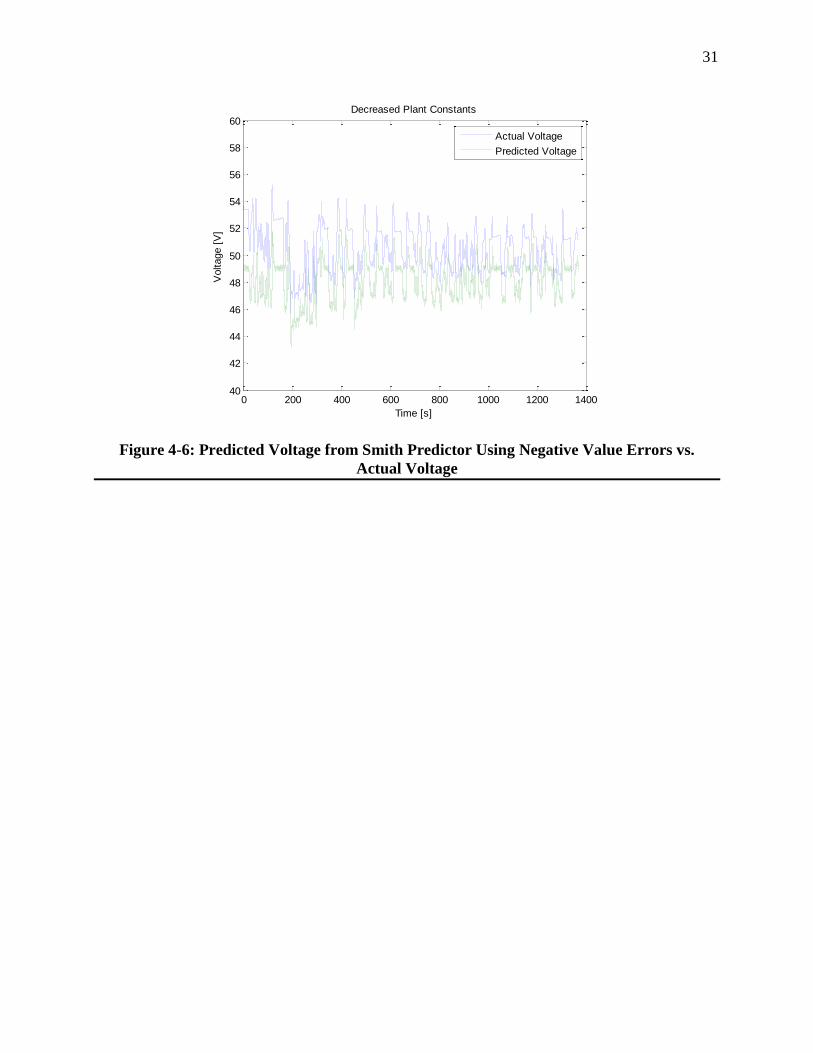
decreased modifications. The controller for the Smith Predictor was tuned to a proportional gain
of 0.65 in an ad-hoc manner (designed via manual tuning) for both simulations. The results are
depicted in Figures 4-5 and 4-6.
From these experiments, it can be concluded that delay compensation of a battery system was
achieved. Discrepancies between the predicted voltage and actual voltage were not related to
dead-time effects in the system. However, significant errors arose from model and real-world
differences. These errors can be attenuated with the use of better models and controller
algorithms.
Figure 4-5: Predicted Voltage from Smith Predictor Using Positive Value Errors vs. Actual
Voltage
0 200 400 600 800 1000 1200 140040
45
50
55
60
65
70
Time [s]
Voltage [
V]
Increased Plant Constants
Actual Voltage
Predicted Voltage
31
Figure 4-6: Predicted Voltage from Smith Predictor Using Negative Value Errors vs.
Actual Voltage
0 200 400 600 800 1000 1200 140040
42
44
46
48
50
52
54
56
58
60
Time [s]
Voltage [
V]
Decreased Plant Constants
Actual Voltage
Predicted Voltage

32
Chapter 5 : Conclusions
The objective of this thesis was achieved with the successful compensation of delay for a
simulated HIL test of a battery system using a Smith Predictor. The results of this work showed
that delay compensation of HIL systems is easily achievable when the delay is known. The
greatest obstacle in using a Smith Predictor lies in the development of a model capable of
representing the dynamics of the real system.
Future work beyond this thesis should focus on the application of real-world situations to the
Smith Predictor and the design of the controllers for such systems in a systematic fashion. The
integration of a real battery to the system would truly test the quality of the predicted signals.
The experimentation of different battery models, such as the one in PSAT, would also serve to
optimize the predictive output of the Smith Predictor. Aside from using predefined inputs, real-
world current demands could be applied using a driving simulator. Real-world dead-times and
geographic separations can be incorporated as latency variables to the system as well.
Delay compensation using the Smith Predictor can also be applied to other vehicle powertrain
components. Ideally, researchers could run multiple HIL experiments on different pieces of
hardware as if they were joined in one system functioning in real-time from separate locations.

33
Appendix A
MATLAB Code for Generating Plots and Constants for Battery Model
%PSAT Simulated Voltage vs. Actual HIL Battery Voltage
%load co_sim_data_nov_15_2103_good.mat
% Define Variables t = tout; %Time sim = yout(:,27); %Simulated Internal Voltage of Battery from PSAT i = yout(:,73); %Current drawn by ABC 150 v = yout(:,74); %Measured Voltage of Battery p = yout(:,40); %PSAT Terminal Battery Model Voltage
%Plot simulated PSAT Battery voltage vs. Measured Battery Voltage plot(t,sim,t,v) xlabel('Time') ylabel('Voltage') legend('PSAT Voltage','Measured Battery Voltage') title('PSAT Simulated Voltage vs. Measured Battery Voltage')
%Plot Current vs. Voltage figure(2) plotyy(t,i,t,v) xlabel('Time') legend('Current','Voltage') title('Current vs. Voltage')
%Attenuate noise using Butterworth Filter [B,A] = butter(2,.005) %use butterworth filter to attenuate noise, %2nd order, .005 cut off for a sample rate of .01
nv = filtfilt(B,A,v); ni = filtfilt(B,A,i); np = filtfilt(B,A,p);
%Plot new voltage comparison figure(3) plot(t,sim,t,nv) xlabel('Time [s]') ylabel('Voltage [V]') title('Internal Voltage vs. Actual Voltage') legend('Simulated Internal Voltage','Actual Voltage')
%Compare Voltage sag to current demand vsag = sim - nv; %Difference in Measured Voltage and PSAT Voltage is %voltage lost to internal resistance figure(4) subplot(2,1,1), plot(t,ni) xlabel('Time') ylabel('Current') title('Filtered Current') subplot(2,1,2), plot(t,vsag) xlabel('Time')

34
ylabel('Voltage Sag') title('Voltage Sag')
%Detrend the Voltage sag data vdetrend = detrend(vsag); %Removes slight voltage climb figure(5) plot(t,vsag,t,vdetrend) xlabel('Time') ylabel('Voltage') legend('Voltage Sag','Detrend Voltage Sag') title('Voltage Sag vs. Detrend Voltage Sag')
%Remove offset after detrend vdoff = vdetrend + (vsag(1,1)-vdetrend(1,1)); %Return offset to the same as %before detrend figure(6) plot(t,vdoff) xlabel('Time') ylabel('Voltage') title('Detrend Voltage With Offset')
%Plot new Voltage Sag with Current figure(7) subplot(2,1,1), plot(t,ni) xlabel('Time [s]') ylabel('Current [A]') title('Current') subplot(2,1,2), plot(t,vdoff) xlabel('Time [s]') ylabel('Voltage [V]') title('Internal Resistance Voltage')
%Regression to find R internal R = ((ni'*ni)^-1)*(ni'*vdoff) % Regression to solve for internal resistance
%Define Values to run in Simulink itest = [t, ni]; c = 229580 %20Amps * 11479seconds (total discharge time) per volt vo = yout(1,74) %Initial voltage of the battery
%Tune the Battery Model to match the Real Battery %Original c = 229580F %Original R = .034ohms %Original vo = 53.7 %Tuned c = 195000F => 15% difference %Tuned R = .0355ohms => .2% difference %Tuned vo = 53.2 => 1% difference
%Compare Model vs PSAT Model vs Actual Voltage figure(8) subplot(3,1,1), plot(t,nv,t,np) xlabel('Time [s]') ylabel('Voltage [V]') title('Actual Voltage vs. PSAT Model Voltage') legend('Actual Voltage','PSAT Model Voltage')

35
subplot(3,1,2), plot(t,nv,time,VEQ) xlabel('Time [s]') ylabel('Voltage [V]') title('Actual Voltage vs. Battery Model Voltage') legend('Actual Voltage','Battery Model Voltage') ylim([40 60]) subplot(3,1,3), plot(t,nv,time,VBT) xlabel('Time [s]') ylabel('Voltage [V]') title('Actual Voltage vs. Tuned Battery Model Voltage') legend('Actual Voltage','Tuned Battery Model Voltage') ylim([40 60])
% Test different error blocks on Smith Predictor
%Ideal Case figure(9) plot(t,nv,t2, Ypd) xlabel('Time [s]') ylabel('Voltage [V]') title('Smith Predictor Voltage') legend('Actual Voltage','Predicted Voltage') ylim([40 60])
%Parameter Increases figure(10) plot(t,nv,t2, YpU) xlabel('Time [s]') ylabel('Voltage [V]') title('Increased Plant Constants') legend('Actual Voltage','Predicted Voltage') ylim([40 70])
%Parameter Decreases figure(11) plot(t,nv,t2, YpD) xlabel('Time [s]') ylabel('Voltage [V]') title('Decreased Plant Constants') legend('Actual Voltage','Predicted Voltage') ylim([40 60])

36
References
[1] S. Brennan and M. Petersheim. “Scaling of hybrid-electric vehicle powertrain
components for Hardware-in-the-loop simulation,” Elsevier Mechatronics, 19(7): pp.1.
2009.
[2] K. Balke, R. Engelbrecht, and C. Poe. “Development of a Distributed Hardware-In-The-
Loop Simulation System for Transportation Networks,” presented at 78th Annual
Transportation Research Board. pp. 2-4, 22. 1999.
[3] R. Isermann, J. Schaffnit, and S. Sinsel. “Hardware-in-the-loop simulation for the design
and testing of engine-control systems,” Control Engineering Practice, 7(5): pp. 1, 10.
1998
[4] M. Petersheim. “Scaling of Hybrid-Electric Vehicle Powertrain Components for
Hardware-in-the-Loop Simulation,” M.S. thesis, Mech. and Nuc. Eng. Dept., Penn. State
Univ., University Park, PA. 2008.
[5] H.K. Fathy, Z.S. Filipi, J.L. Stein, and J. Hagena. “Review of Hardware-in-the-Loop
Simulation and Its Prospects in the Automotive Area,” Proc. of SPIE, 6228, pp. 1, 15.
2006.
[6] R. Ahlawat, D. Assanis, H.K. Fathy, Z. Filipi, J. Hagena, D. Jung, A. Knafl, J. Liu, H.
Peng, and J. Stein. “Engine-in-the-Loop Testing for Evaluating Hybrid Propulsion
Concepts and Transient Emissions – HMMWV Case Study,” SAE International, pp. 1, 2,
16. 2006.
[7] R. Ahlawat, H.K. Fathy, Z.S. Filipi, J.R. Hagena, and J.L. Stein. “Volterra Series
Estimation of Transient Soot Emissions from a Diesel Engine,” pp. 1, 2, 6. 2010.
[8] H. Kim and H. Yeo. “Hardware-in-the-Loop simulation of regenerative braking for a
hybrid electric vehicle,” Proc Instn Mech Engrs, 206 Part D, pp. 855, 864. 2002.
[9] M. Brudnak, T. Ersal, H.K. Fathy, and J.L. Stein. “Transparency Analysis in Internet-
Distributed Hardware-in-the-Loop Simulation,” IEEE Transaction on Mechatronics, pp.
14, 18, 21, 23. 2010.
[10] M. Brudnak, T. Ersal, H.K. Fathy, Z. Filipi, A. Salvi, and J.L. Stein. “Development and
model-based transparency analysis of an Internet-distributed hardware-in-the-loop
simulation platform,” Elsevier Mechatronics, pp. 1-4, 6-7. 2010.
[11] D.L. Mills. “Internet Time Synchronization: The Network Time Protocol,” IEEE
Transactions on Communications, 39, 10, pp. 1482, 1491-1492. 1991.
[12] J.M. Montenbruck. “Controlling Distributed Systems with Delay in Presence of Realtime
Requirements,” M.S. thesis, Mech. and Nuc. Eng. Dept., Penn. State Univ., University
Park, PA. 2011.

37
[13] Department of Energy and Idaho National Engineering & Environmental Laboratory
Technical Staff, FreedomCAR, Department of Energy and Idaho National Engineering &
Environmental Laboratory, 2003.
[14] N. Abe and K. Yamankaka. “Smith Predictor Control and Internal Model Control – A
Tutorial-,” presented at SICE Annual Conference in Fukui, Fukui University, Japan.
2003.
[15] Otto J. Smith. Closer Control of Loops with Dead Time. Chemical Engineering Progress,
53:217–219, 1957.
[16] Otto J. Smith. A Controller to Overcome Dead Time. ISA J, 6:28–33, 1959.
[17] J. Normey-Rico and E. Camacho. Control of Dead-Time Processes. Springer, 2007.
[18] T.P. Cleary. “Development and Testing of a Flexible Topology Micro-Hybrid Passenger
Vehicle Powertrain for Hardware-in-the Loop Simulation and Education,” M.S. thesis,
Mech. and Nuc. Eng. Dept., Penn. State Univ., University Park, PA. 2010.

Vita
David Chen EDUCATION: The Pennsylvania State University; University Park, PA
The Schreyer Honors College
B.S. in Mechanical Engineering, expected May 2011
Relevant Courses Taken:
Materials Response Dynamics Eng. Design Fluid Mechanics
Thermodynamics Macroeconomics Mechanical Design
________________________________________________________________________________
EXPERIENCE: Penn State Research – Sean Brennan Dynamic Systems and Control (Penn State,
08/23/10 – Present)
Conducted research on the application of synchronization to Hardware-in-the-
Loop systems
ExxonMobil – Facilities Engineering Programmatics (Houston TX, 05/17/10 -
08/13/10)
Worked as an Instrumentation and Controls Engineer to develop programs to
manage and sustain the integrity of industrial systems on a global scale
Developed Spare Parts Management Plan as part of the Industrial Control
Systems Life Cycle Management initiative across ExxonMobil upstream
Analyzed existing taxonomies to construct a Global Taxonomy for the
implementation of a new asset management tool
Department of Defense - Aberdeen Test Center (Aberdeen MD, 05/11/09 – 07/31/09)
Held Secret level security clearance
Certified Assistant Test Director for the Department of Defense
Responsible for testing of small arms weapons for the army from start to finish
Penn State Research – Stephane Coutu CREST Project (Penn State, 05/08 – 05/09)
Research assistant in the construction of a Cosmic Ray Sensor to be flown in
cooperation with other universities and NASA in Antarctica
Assembled scintillator paddles and fabricated circuit boards for the sensor veto
system
Built photomultipiler tubes and ultravolts to detect high energy particles
________________________________________________________________________________
HONORS/AWARDS: Oracle Database Competition – 5th place worldwide (2005), AP Scholar Award,
Weiss Breakthrough Scholar, Selembo Trustee Scholar

_____________________________________________________________________________________
ACTIVITIES: Athletics – Club Cross Country (Held positions of President, Captain, Merchandise chair,
and Webmaster), Track, Intramural Volleyball
Volunteering - Salvation Army Volunteer, Student volunteer at PSU Career Fair,
volunteered time at Mariner and Oaks retirement homes, Fresh Start team leader
Clubs - American Society of Mechanical Engineers, Penn State IFC/Panhellenic Dance
Marathon – raised 36 thousand dollars for the Four Diamonds Fund and enlisted aid of
high school Key Clubbers