department of electronics and communication...
TRANSCRIPT

Course Code : CS6551
Course : COMPUTER NETWORKS
Year : III
Semester : VI
Prepared By,
Mrs. S.Surya M.E.,
AP/CSE
DEPARTMENT OF ELECTRONICS AND COMMUNICATION ENGINEERING
QUESTION BANK
Vision of the Institute
To Develop Globally Competitive Human Resource through Virtuous Enlightened Learning
Mission of the Institute
M1: To Impart Quality Technical Education and Research Orientation Enabling
the Technocrats to Fair Well in Global Competition
M2: To Inculcate Committed Leadership Qualities through Ethical Practices
M3: To Acquire Skills through Industry Practices and Develop the habit of life-long
learning
DEPARTMENT OF ELECTRONICS AND COMMUNICATION ENGINEERING
Vision of the Department
To Produce Competent and Responsible Engineers to meet the growing Challenges in the
field of Electronics and Communication Engineering
Mission of the Department
M1: To impart strong technical competency to learners by using best pedagogical methods
M2: To provide industrial exposure to learners by collaboration with industries
for training, internships, and expert talks.
M3: To imbibe self-learning, collaborative learning, Ethical values and
Environment awareness through Co- curricular and Extra-curricular activities.
PEO’s
PEO 1: Adapt to dynamically evolving technologies for a successful career in
an academia/Industry/Entrepreneur
PEO 2: Apply the knowledge of Electronics and communication Engineering to solve
real world problems
PEO 3: Exhibit effective communication skills and can perform as a team player
with leadership traits
PSO’s
PSO 1: Develop Innovative Ideas for an existing / Novel problems through information
and communication technologies.
PSO 2: Apply the Analog and Digital system Design Principles and practices for Developing
Quality products.
PROGRAM OUTCOMES [PO’s]
1. Engineering Knowledge: Apply the knowledge of mathematics, science, engineering
fundamentals, and an engineering specialization to the solution of complex engineering
problems.
2. Problem Analysis: Identify, formulate, research literature, and analyze complex
engineering problems reaching substantiated conclusions using first principles of
mathematics, natural sciences, and engineering sciences.
3. Design/development of Solutions: Design solutions for complex engineering problems
and design system components or processes that meet t h e specified needs with
appropriate consideration for the public health and safety, and the cultural, societal, and
environmental considerations.
4. Conduct Investigations of Complex Problems: Use research-based knowledge and
research methods including design of experiments, analysis and interpretation of data,
and synthesis of the information to provide valid conclusions.
5. Modern Tool usage: Create, select, and apply appropriate techniques, resources, and
modern engineering and IT tools including prediction and modeling to complex
engineering activities with an understanding of the limitations.
6. The Engineer and Society: Apply reasoning informed by the contextual knowledge to
assess societal, health, safety, legal and cultural issues and the consequent
responsibilities relevant to the professional engineering practice.
7. Environment and Sustainability: Understand the impact of the professional
engineering solutions in societal and environmental contexts, and demonstrate the
knowledge of, and need for sustainable development.
8. Ethics: Apply ethical principles and commit to professional ethics and responsibilities
and norms of the engineering practice.
9. Individual and Team Work: Function effectively as an individual, and as a member or
leader in diverse teams, and in multidisciplinary settings.
10. Communication: Communicate effectively on complex engineering activities with the
engineering community and with society at large, such as, being able to comprehend
and write effective reports and design documentation, make effective presentations, and
give and receive clear instructions.
11. Project Management and Finance: Demonstrate knowledge and understanding of the
engineering and management principles and apply these to one’s own work, as a
member and leader in a team, to manage projects and in multidisciplinary environments.
12. Life-long Learning: Recognize the need for, and have the preparation and ability to
engage in independent and life-long learning in the broadest context of technological change.
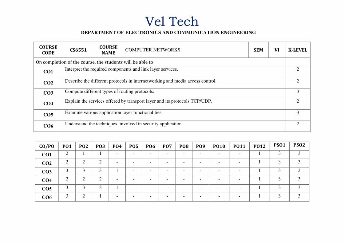
DEPARTMENT OF ELECTRONICS AND COMMUNICATION ENGINEERING
COURSE
CODE CS6551
COURSE
NAME COMPUTER NETWORKS SEM VI K-LEVEL
On completion of the course, the students will be able to
CO1 Interpret the required components and link layer services. 2
CO2 Describe the different protocols in internetworking and media access control. 2
CO3 Compute different types of routing protocols. 3
CO4 Explain the services offered by transport layer and its protocols TCP/UDP. 2
CO5 Examine various application layer functionalities. 3
CO6 Understand the techniques involved in security application 2
CO/PO PO1 PO2 PO3 PO4 PO5 PO6 PO7 PO8 PO9 PO10 PO11 PO12 PSO1 PSO2
CO1 2 1 1 - - - - - - - - 1 3 3
CO2 2 2 2 - - - - - - - - 1 3 3
CO3 3 3 3 1 - - - - - - - 1 3 3
CO4 2 2 2 - - - - - - - - 1 3 3
CO5 3 3 3 1 - - - - - - - 1 3 3
CO6 3 2 1 - - - - - - - - 1 3 3
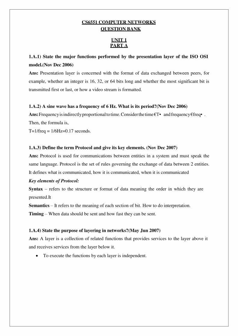
CS6551 COMPUTER NETWORKS
QUESTION BANK
UNIT 1
PART A
1.A.1) State the major functions performed by the presentation layer of the ISO OSI
model.(Nov Dec 2006)
Ans: Presentation layer is concerned with the format of data exchanged between peers, for
example, whether an integer is 16, 32, or 64 bits long and whether the most significant bit is
transmitted first or last, or how a video stream is formatted.
1.A.2) A sine wave has a frequency of 6 Hz. What is its period?(Nov Dec 2006)
Ans: Frequency is indirectly proportional to time. Consider the time €T• and frequency €freq• .
Then, the formula is,
T=1/freq = 1/6Hz=0.17 seconds.
1.A.3) Define the term Protocol and give its key elements. (Nov Dec 2007)
Ans: Protocol is used for communications between entities in a system and must speak the
same language. Protocol is the set of rules governing the exchange of data between 2 entities.
It defines what is communicated, how it is communicated, when it is communicated
Key elements of Protocol:
Syntax – refers to the structure or format of data meaning the order in which they are
presented.It
Semantics – It refers to the meaning of each section of bit. How to do interpretation.
Timing – When data should be sent and how fast they can be sent.
1.A.4) State the purpose of layering in networks?(May Jun 2007)
Ans: A layer is a collection of related functions that provides services to the layer above it
and receives services from the layer below it.
To execute the functions by each layer is independent.
1.A.5) At which level of OSI model does repeaters, bridges, routers and gateways
operate?(May Jun 2007)
1.A.6) For n devices in a network, what is the number of cable links required for a
mesh, ring, bus and star topology?(Nov Dec 2008)
Ans: Cable links required to make communication between €n• network devices.
• Links required for mesh topology = n(n-1)/2
• Links required for ring topology = n-1
• Links required for star topology = n
• Links required for bus topology = one backbone and n drop lines
1.A.7) What are the two types of line configuration? (Nov Dec 2010)
Ans: Point to point line configuration and multipoint line configuration.
Point to point:
□ It provides a dedicated link between 2 devices.
□ Entire capacity of the link is reserved for transmission between 3 devices only
□ Eg: connection between remote control and TV• s control system
Multipoint:
□ Also called as multi drop connection
□ Here the channel capacity is shared
□ If many devices share the link simultaneously it is called spatially shared connection.
1.A.8) What do you mean by error control? (Nov Dec 2010)
Ans: Error control refers to mechanism to detect and correct errors that occur in the
transmission of frames.
Devices Layers
Repeater Physical
Bridge Physical, Data Link
Router Physical, Data Link and Network
All 7 layers Gateway
1.A.9) What is flow control? (Nov Dec 2011)
Ans: Flow control is a technique for assuring that a transmitting entity does not overwhelm a
receiving entity with data. Flow control—a feedback mechanism by which the receiver is
able to throttle the sender. Such a mechanism is used to keep the sender from overrunning the
receiver, i.e., from transmitting more data than the receiver is able to process.
1.A.10) Define Error detection and correction. (Nov Dec 2011)
Ans: Error detection: Sender transmits every data unit twice. Receiver performs bit-by-bit
comparison between that two versions of data. Any mismatch would indicate an error, which
needs error correction.
1.A.11) What are the issues in data link layer? (Nov Dec 2012)
Ans: The Data Link Layer is the protocol layer which transfers data between adjacent
network nodes in a wide area network or between nodes on the same local area network
segment. The Data Link Layer provides the functional and procedural means to transfer data
between network entities and might provide the means to detect and possibly correct errors
that may occur in the Physical Layer. Examples of data link protocols are Ethernet for local
area networks (multi-node), the Point-to-Point Protocol (PPP), HDLC and ADCCP for point-
to-point (dual-node) connections.
1.A.12) What is ARQ? (Dec 10)
Ans: Automatic repeat request(ARQ).In error control mechanism when an error is detected in
an exchange, specified frames are retransmitted. This process is called ARQ.
1.A.13) What are the functions of application layer? (May 11)
Ans: User to access information on the network through an application. This layer is the main
interface for the user to interact with the application.
1.A.14) Define bit stuffing. (May 11)
Ans: Each frame begins and ends with a special bit pattern called flag byte. Whenever sender
data link layer encounters five consecutive ones in the data stream, it automatically stuffs a 0
bit into the outgoing stream.

1.A.15) Difference between circuit switching and packet switching. (May 11)
circuit switching packet switching
Physical connection b/w sender and receiver No Physical connection b/w sender and receiver
All packets use same path All packets use different path
Waste of bandwidth is possible Waste of bandwidth is not possible
Congestion occurs for per minute Congestion occurs for per packet
1.A.16) What is HDLC? (May 12)
Ans: It is a protocol that implements ARQ mechanisms. It supports communication over
point – to – point or point – to – multipoint links.
1.A.17) Define a layer. (Dec 13)
Ans: A layer is a collection of related functions that provides services to the layer above it
and receives services from the layer below it.To executed the functions by each layer is
independent.
1.A.18) What do you mean by framing? (Dec-13)
Ans: The DLL translates the physical layers raw bit stream into discrete units called frames.
Framing in DLL separates messages from one source to a destination, or from other messages
to other destination, by adding sender and receiver address.

UNIT 1
PART B
1.B.1) (i) What is a Protocol? List the three key elements of a protocol.(4) (Dec 08)
Ans: Protocol is used for communications between entities in a system and must speak the
same language. Protocol is the set of rules governing the exchange of data between 2 entities.
It defines what is communicated, how it is communicated, when it is communicated
Key elements of Protocol:
Syntax – refers to the structure or format of data meaning the order in which they are
presented.It
Semantics – It refers to the meaning of each section of bit. How to do interpretation.
Timing – When data should be sent and how fast they can be sent.
1.B.2)
(ii) With relevant examples differentiate between simplex, half duplex and full duplex
communication. (4)
Ans: Communication system is a system composed of two connected parties or devices
which can communicate with one another in one way or two way directions. The
communication between two devices can be simplex or half duplex or full duplex.
Simplex: Communication is unidirectional. A simplex communication is one where all
signals can flow in only one direction. These types of systems are often employed in
broadcast networks, where the receivers do not need to send any data back to the
transmitter/broadcaster.
Duplex: A duplex communication system is a system composed of two connected parties or
devices which can communicate with one another in both directions.
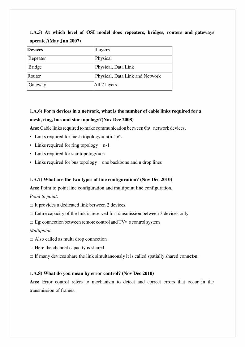
Half-Duplex: A half-duplex system provides for communication in both directions, but only
one direction at a time. Once a party begins receiving a signal, it must wait for the transmitter
to stop transmitting, before replying.
Full-Duplex: A full-duplex, or sometimes double-duplex system allows communication in both
directions, and unlike half-duplex, allows this to happen simultaneously.
(iii) A Sine wave completes one cycle in 25 go, what is its frequency? Express the
frequency in KHz. (4).
Consider the given time €T• is 25 μs.
To calculate the frequency we have a formula,
Frequency = 1/T
=1/0.000025 =40000 (or) 40 KHz.
(iv) A digital signal has a bit interval of 40 microseconds. What is the bit rate? Express the bit
rate in Steps. (4) (Nov Dec 2006).
Consider the given bit interval is 40 μs. The bit rate and bit intervals are inversely
proportional to each other. So, we can get the formula to calculate the bit rate is,
Bit rate=1/bit
interval =1/0.000040 =25kbps.
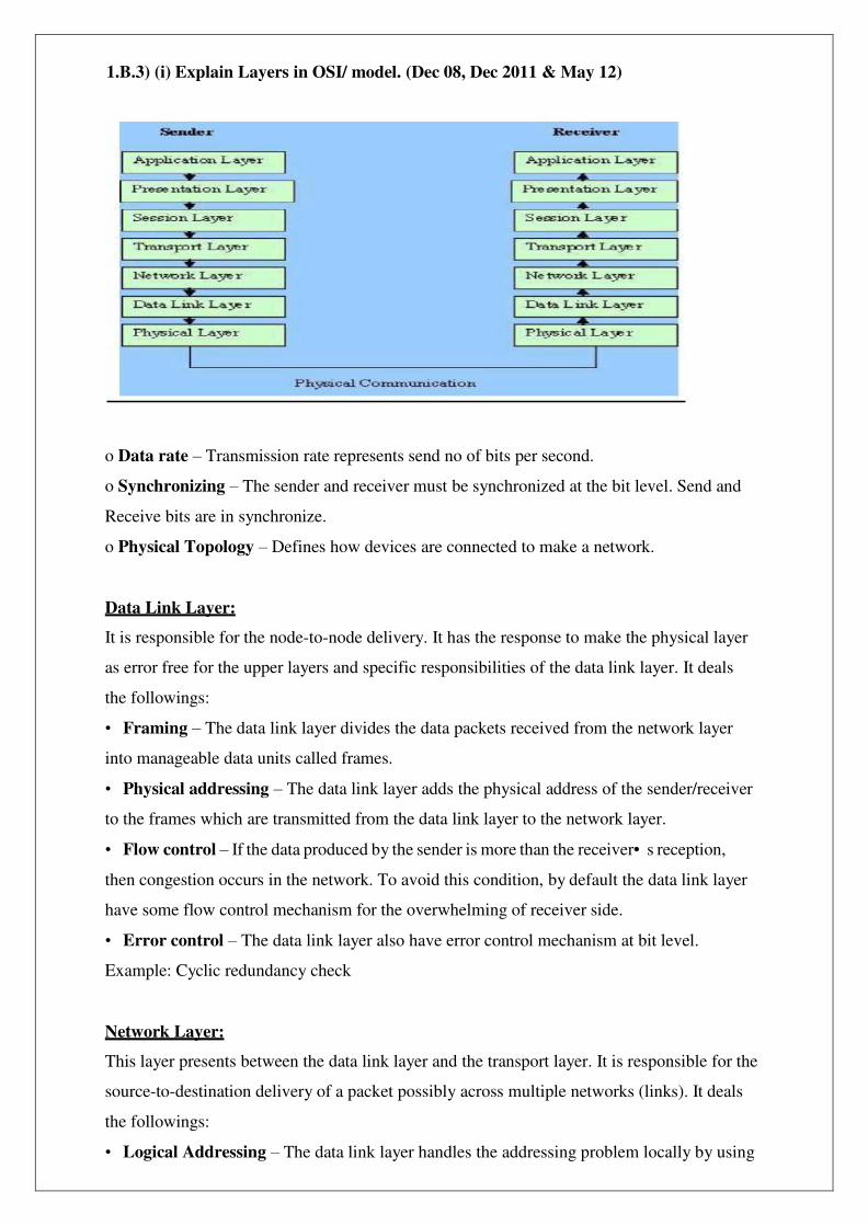
1.B.3) (i) Explain Layers in OSI/ model. (Dec 08, Dec 2011 & May 12)
o Data rate – Transmission rate represents send no of bits per second.
o Synchronizing – The sender and receiver must be synchronized at the bit level. Send and
Receive bits are in synchronize.
o Physical Topology – Defines how devices are connected to make a network.
Data Link Layer:
It is responsible for the node-to-node delivery. It has the response to make the physical layer
as error free for the upper layers and specific responsibilities of the data link layer. It deals
the followings:
• Framing – The data link layer divides the data packets received from the network layer
into manageable data units called frames.
• Physical addressing – The data link layer adds the physical address of the sender/receiver
to the frames which are transmitted from the data link layer to the network layer.
• Flow control – If the data produced by the sender is more than the receiver• s reception,
then congestion occurs in the network. To avoid this condition, by default the data link layer
have some flow control mechanism for the overwhelming of receiver side.
• Error control – The data link layer also have error control mechanism at bit level.
Example: Cyclic redundancy check
Network Layer:
This layer presents between the data link layer and the transport layer. It is responsible for the
source-to-destination delivery of a packet possibly across multiple networks (links). It deals
the followings:
• Logical Addressing – The data link layer handles the addressing problem locally by using

the physical address, outside the network we need one more address named logical address.
The network layer adds a header to the packet coming from the upper layer includes the
logical addresses of sender/receiver.
• Routing – In routing, some routing devices (like routers, gateways) take a part to play with
the data packets, to reach the final destination.
Transport Layer:
The transport layer is responsible for end-to-end delivery of the entire message. For added
security, the transport layer may create a connection between the two end ports involves three
steps: connection establishment, data transfer, connection release. The transport layer has
more control over sequencing, flow and error detection and correction.
Application Layer:
Application layer provides user interfaces and support for services such as electronic mail,
remote file access and transfer, shared database management, and other types of distributed
information devices. It deals the following:
• File transfer, access, and management (FTAM)
• Mail services
• Directory services
Application layer protocols: Telnet, SMTP, SNMP, HTTP, FTP.
1.B.3 (i) Explain about the transmission modes available for data flow.
Three transmission modes are available for data flow.
• Simplex : One way communication, unidirectional. Any one of the station can transmit
and other can receive.
• Half Duplex : Each station can both transmit and receive, but not at the same time. When
one is sending, another is receiving. It is two-directional traffic. Examples – Walkie-talkies.
• Full Duplex : Both stations can transmit and receive simultaneously
(ii) Explain the categories of networks. (Nov Dec 2007).
Three categories of networks are generally we can refer while we speak about the networks.
They are,
1. Local Area Network (LAN)
2. Metropolitan Area Network (MAN)
3. Wide Area Network (WAN)
Local Area Network (LAN)
Local Area Network is usually privately owned and links the devices in a single office,

buildings, or campus. LAN size is limited to few kilometers. LANs are designed to allow
resources to be shared between personal computers or workstations. The resources to be
shared can include hardware, software or data. LANs are distinguished from other types of
networks by their transmission media and topology. The most common LAN topologies are
bus, ring and star.
Metropolitan Area Network (MAN)
Metropolitan Area Network is designed to extend over an entire city. It may be a single
network such as a cable television network or it may be a connection of number of LAN• s
into a larger network. This service provide by private, public companies or by local telephone
company. Telephone companies provide a popular MAN service named “Switched Multi-
megabit Data Services (SMDS)”
Wide Area Network (WAN)
A Wide area network (WAN) provides long distance transmission of data, voice, image, and
video information over large geographical areas that may comprise a country, a continent, or
even the whole world. A WAN is wholly owned and used by a single company is often
referred to as an enterprise network.
1.B.4) Explain in detail the error detection and error corrections. (Nov Dec 2010, Dec
2012, Dec 10, 12, May 12).
Ans: Error Detection- Sender transmits every data unit twice. Receiver performs bit-by-bit
comparison between those two versions of data. Any mismatch would indicate an error,
which needs error correction. Advantage is it is very accurate. Disadvantage is time
consuming.
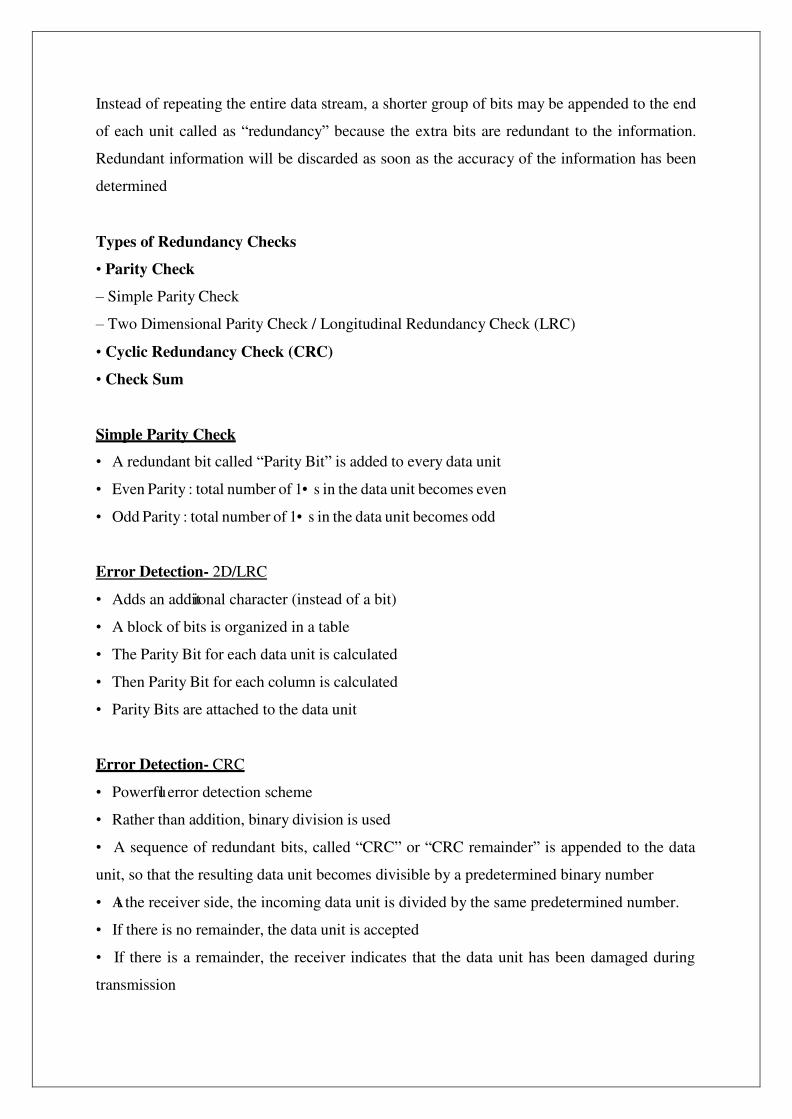
Instead of repeating the entire data stream, a shorter group of bits may be appended to the end
of each unit called as “redundancy” because the extra bits are redundant to the information.
Redundant information will be discarded as soon as the accuracy of the information has been
determined
Types of Redundancy Checks
• Parity Check
– Simple Parity Check
– Two Dimensional Parity Check / Longitudinal Redundancy Check (LRC)
• Cyclic Redundancy Check (CRC)
• Check Sum
Simple Parity Check
• A redundant bit called “Parity Bit” is added to every data unit
• Even Parity : total number of 1• s in the data unit becomes even
• Odd Parity : total number of 1• s in the data unit becomes odd
Error Detection- 2D/LRC
• Adds an addiitonal character (instead of a bit)
• A block of bits is organized in a table
• The Parity Bit for each data unit is calculated
• Then Parity Bit for each column is calculated
• Parity Bits are attached to the data unit
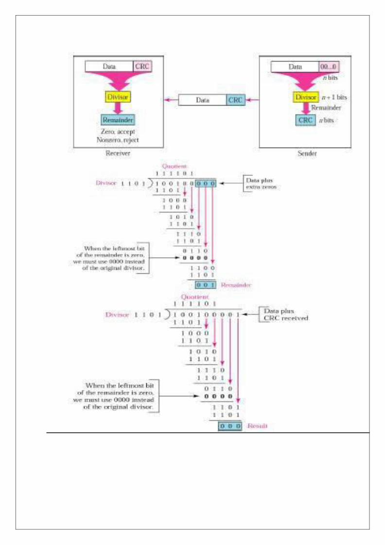
Error Detection- CRC
• Powerful error detection scheme
• Rather than addition, binary division is used
• A sequence of redundant bits, called “CRC” or “CRC remainder” is appended to the data
unit, so that the resulting data unit becomes divisible by a predetermined binary number
• At the receiver side, the incoming data unit is divided by the same predetermined number.
• If there is no remainder, the data unit is accepted
• If there is a remainder, the receiver indicates that the data unit has been damaged during
transmission
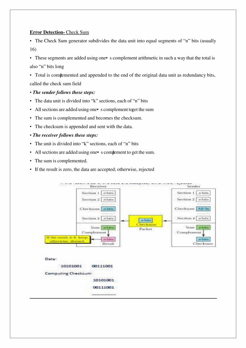
Error Detection- Check Sum
• The Check Sum generator subdivides the data unit into equal segments of “n” bits (usually
16)
• These segments are added using one• s complement arithmetic in such a way that the total is
also “n” bits long
• Total is complemented and appended to the end of the original data unit as redundancy bits,
called the check sum field
• The sender follows these steps:
• The data unit is divided into “k” sections, each of “n” bits
• All sections are added using one• s complement toget the sum
• The sum is complemented and becomes the checksum.
• The checksum is appended and sent with the data.
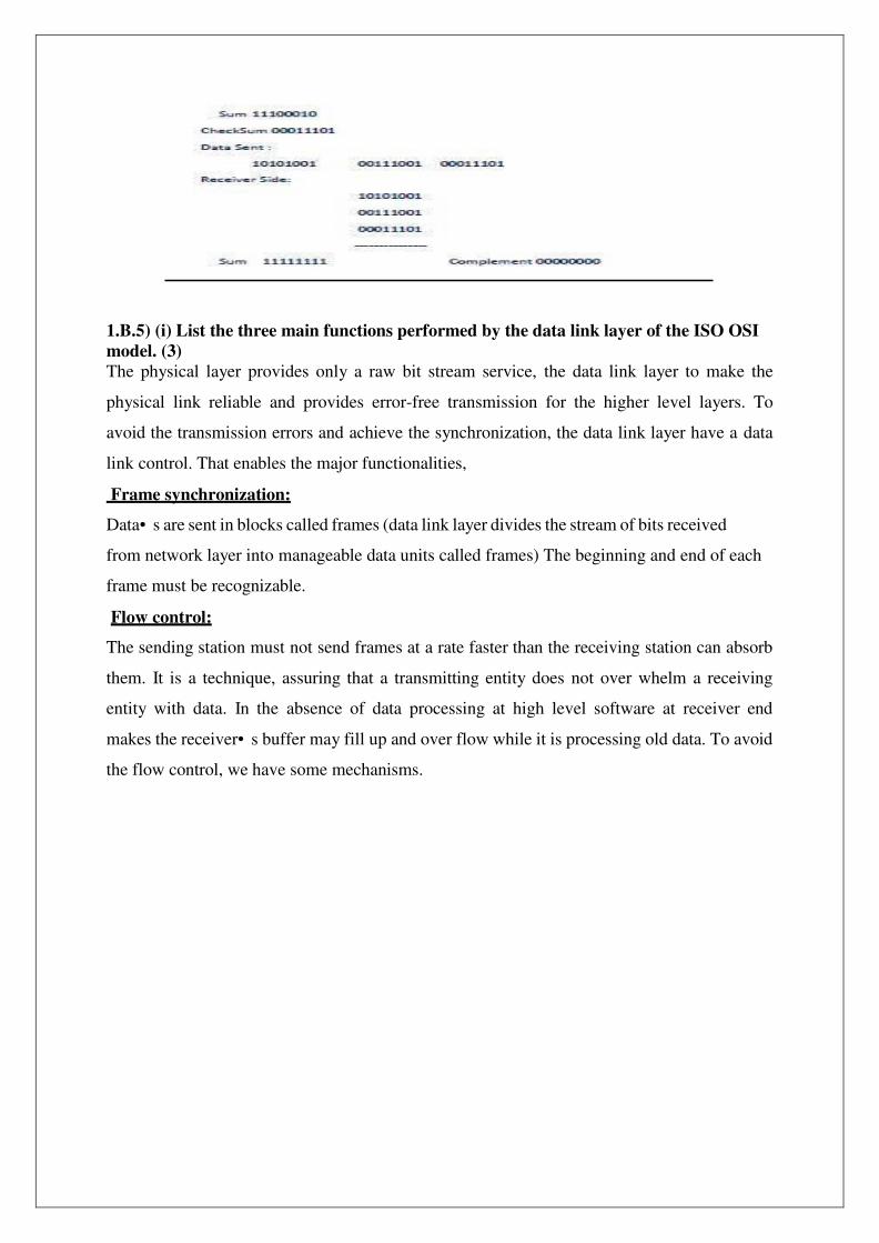
• The receiver follows these steps:
• The unit is divided into “k” sections, each of “n” bits
• All sections are added using one• s complement to get the sum.
• The sum is complemented.
• If the result is zero, the data are accepted; otherwise, rejected
1.B.5) (i) List the three main functions performed by the data link layer of the ISO OSI
model. (3)
The physical layer provides only a raw bit stream service, the data link layer to make the
physical link reliable and provides error-free transmission for the higher level layers. To
avoid the transmission errors and achieve the synchronization, the data link layer have a data
link control. That enables the major functionalities,
Frame synchronization:
Data• s are sent in blocks called frames (data link layer divides the stream of bits received
from network layer into manageable data units called frames) The beginning and end of each
frame must be recognizable.
Flow control:
The sending station must not send frames at a rate faster than the receiving station can absorb
them. It is a technique, assuring that a transmitting entity does not over whelm a receiving
entity with data. In the absence of data processing at high level software at receiver end
makes the receiver• s buffer may fill up and over flow while it is processing old data. To avoid
the flow control, we have some mechanisms.

1. stop-wait-wait Flow Control.
2. Sliding-window Flow Control.
Error control:
It refers to mechanisms to detect and correct errors that occur in the transmission of frames.
Bit errors introduced by the transmission system should be corrected.
We admit the possibility of two types of errors:
1. Lost frame: A frame fails to arrive at the other side. For example, a noise burst may
damage a frame to the extent that the receiver is not aware that a frame has been transmitted.
2. Damaged frame: A recognizable frame does arrive, but some of the bits are in error (have
been altered during transmission).
The most common techniques for avoiding error control:
1. Error detection: Resulting errors by change of one or more bits in a transmitted frames.
2. Positive acknowledgement: The destination returns a positive acknowledgement to
successfully received, error-free frames.
3. Retransmission after timeout: The source retransmits a frame that has not been
acknowledged after a predetermined amount of time.
4. Negative acknowledgement and retransmission: The destination returns a negative
acknowledgement to frames in which an error is detected. The source retransmits such
frames.
Addressing:
On a multipoint line, such as a local area network (LAN), the identify of the two Stations
involved in a transmission must be specified.
Control and data on same link:
It is usually not desirable to have a physically separate communications path for control
information. Accordingly, the receiver must be able to distinguish control information from
the data being transmitted.
Link management:
The initiation, maintenance and termination of a sustained data exchange requires a fair
amount of coordination and cooperation among stations. Procedures for the management of
this exchange are required.

1.B.6) Explain CRC error detection mechanism with example (Dec 10,12)
CRC is an error-detecting code. Its computation resembles a long division operation in which
the quotient is discarded and the remainder becomes the result, with the important distinction
that the arithmetic used is the carry-less arithmetic of a finite field. The length of the
remainder is always less than or equal to the length of the divisor, which therefore determines
how long the result can be. The definition of a particular CRC specifies the divisor to be
used, among other things.
Although CRCs can be constructed using any finite field, all commonly used CRCs employ
the finite field, the field of two elements, usually called 0 and 1, comfortably matching
computer architecture. An important reason for the popularity of CRCs for detecting the
accidental alteration of data is their efficiency guarantee. Typically, an n-bit CRC, applied to
a data block or arbitrary length, will detect any single error burst not longer than n bits and
will detect a fraction 1-2-n of all longer error bursts. Errors in both data transmission
channels and magnetic storage media tend to be distributed non-randomly, making CRC
properties more useful than alternative schemes such as multiple parity checks.
Computation of CRC:
The mechanics of computing an n-bit binary CRC are simple. The bits representing the input
are lined up in a row, and the (n+1)-bit pattern representing the CRC's divisor (called a
"polynomial") is positioned underneath the left-hand end of the row. Here is the first
calculation for computing a 3-bit CRC:
11010011101100 <--- Input
1011 <--- divisor (4 Bits)
01100011101100 <--- result
If the input bit above the leftmost divisor bit is 0, do nothing and move the divisor to the right
by one bit. If the input bit above the leftmost divisor bit is 1, the divisor is exclusive-ORed
into the input (in other words, the input bit above each 1-bit in the divisor is toggled). The
divisor is then shifted one bit to the right, and the process is repeated until the divisor reaches
the right-hand end of the input row. Here is the last calculation:
00000000001110 <--- result of multiplication calculation
1011 <--- divisor
--------------
00000000000101 <--- remainder (3 bits)

Since the leftmost divisor bit zeroed every input bit it touched, when this process ends the
only bits in the input row that can be nonzero are the n bits at the right-hand end of the row.
These n bits are the remainder of the division step, and will also be the value of the CRC
function (unless the chosen CRC specification calls for some post processing.
1.B.7) (i) A block of 32 bits has to be transmitted. Discuss how the thirty two bit block is
transmitted to the receiver using Longitudinal Redundancy Check. (6)
Longitudinal redundancy check(LRC) is an error-detection method dividing a data unit into
rows and columns and performing parity checks on corresponding bits of each column.
In LRC the block of data is arranged in a table (rows and columns)
The block of 32 bits may be separated and arranged in 4 rows and 8 columns.
The least significant bits are added together and their parity found; then the second
bits are added and their parity found and so on.
At last a new sequence of 8 bit is found, that sequence also be added with the original
32 bits of data.
This newly added sequence is used for LRC checking purpose.
Example:
11100111 11011101 00111001 10101001
11100111 11011101 00111001 10101001 -------------------- 10101010
The data will ready to transmit is,
11100111 11011101 00111001 10101001 10101010
(ii) Consider 5 32 bit block of data 11100111 11011101 00111001 10101001 that has to be
transmitted. If Longitudinal Redundancy Check is used what is the transmitted bit
stream? (4)
Longitudinal redundancy check(LRC) is an error-detection method dividing a data unit into
rows and columns and performing parity checks on corresponding bits of each column.
• In LRC the block of data is arranged in a table (rows and columns)
• The block of 32 bits may be separated and arranged in 4 rows and 8 columns.
• The least significant bits are added together and their parity found; then the second bits are
added and their parity found and so on.
• At last a new sequence of 8 bit is found, that sequence also be added with the original 32
bits of data.

• This newly added sequence is used for LRC checking purpose.
Example:
11100111 11011101 00111001 10101001
11100111 11011101 00111001 10101001 -------------------- 10101010
The data will ready to transmit is,
11100111 11011101 00111001 10101001 10101010.
(iii) In the Hamming code, for a data unit of m into how do you compute the number of
redundant bits needed? (3)
In the Hamming code, the required redundant bits €r• computation is based on the data
unit.To calculate the no of redundant bits r, we use the below given formula,
2r > = m +r+1
m - Data unit size in bits.
r - Redundant bit size.
Example: The Data unit has 10 bits then the redundant bit calculation will be, 24>= 10+4+1
*Redundant bits required to correct the data unit is equal or greater than 4.
(iv) What kinds of error can Vertical Redundancy check determine? What kinds of
errors it cannot determine? (3) (Nov Dec 2006).
The vertical redundancy check (VRC) is used for odd and even parity checking. A way of
error checking by attaching a parity bit to each byte of data to be transmitted, which is then
tested to determine if the transmission is correct.
1.B.8) Name four network topologies and explain them giving all features. (Dec 10)
Mesh
Star
Ring
Bus
1.B.9) Explain in detail about HDLC. (May 11, 13)
High-Level Data Link Control (HDLC) is a bit-oriented code-transparent
synchronous data link layer protocol developed by the International Organization for
Standardization (ISO).
Types of stations:
Primary
Secondary
Combined
Operation mode of HDLC
Frames
Control field
UNIT 2
PART A
2.A.1) What is CSMA/CD? .(Nov Dec 2011)
Ans: Carrier sense multiple access with collision detection (CSMA/CD) is a Media
Access Control method,
• a carrier sensing scheme is used.
• a transmitting data station that detects another signal while transmitting a frame, stops
transmitting that frame, transmits a jam signal, and then waits for a random time interval
before trying to resend the frame.
2.A.2) What is meant by bridge? .(Nov Dec 2011)
Ans: A network bridge connects multiple network segments (network domains) along the
data link layer. It is sometimes called a network switch, and it works by using bridging.
Traffic from one network is forwarded through it to another network. The bridge simply does
what its name entails, by connecting two sides from adjacent networks
2.A.3) Differentiate fast ethernet and gigabit ethernet. .(Nov Dec 2012)
Ans: The 'Ether' part of Ethernet denotes that the system is not meant to be restricted for use
on only one medium type, copper cables, fibre cables and even radio waves can be used.
Fast Ethernet Network was developed as an upgrade to traditional Ethernet Networking. Fast
Ethernet improved traditional Ethernet by increasing transfer rates 10 times, from 10 Megabit
to 100 Megabit speed.
Gigabit Ethernet Network is an upgrade on Fast Ethernet Network equivalent to Fast Ethernet
Networks improvement over Fast Ethernet Network, offering speeds of 1000 Megabits (1
Gigabit)
2.A.4) What is the difference between switch and bridge? .(Nov Dec 2012)
Ans: The difference between switch and bridge are,
1. Bridge is is device which divides a network into two. Switch connects multiple networks.
2. Bridge are software based and switch is a hardware based.

3. Bridge can have upto 16 ports while switch can handle many ports.
4. Bridge is rarely used. Switches are frequently used.
2.A.5) Compare a piconet and a scatter net. .(Nov Dec 2008)
Ans: A piconet is the type of connection that is formed between two or more Bluetooth-
enabled devices, one device takes the role of 'master', and all other devices assume a 'slave'
role for synchronization reasons.
scatternet is a number of interconnected piconets that supports communication between more
than 8 devices. Scatternets can be formed when a member of one piconet elects to participate
as a slave in a second, separate piconet.
2.A.6) What are the functions of Bridges? .(Nov Dec 2010)
Ans: A bridge device filters data traffic at a network boundary. Bridges reduce the amount of
traffic on a LAN by dividing it into two segments.
Bridges operate at the data link layer (Layer 2) of the OSI model. Bridges inspect incoming
traffic and decide whether to forward or discard it. An Ethernet bridge, for example, inspects
each incoming Ethernet frame - including the source and destination MAC addresses, and
sometimes the frame size - in making individual forwarding decisions.
2.A.7) Which class does the following IP address belong to? .(Nov Dec 2006)
(a) 157.143.252.207 (b) 93.31.1.245
Ans:
1. This IP address comes under Class B.
2. This IP address comes under Class A.
2.A.8) Is the size of the ARP packet fixed? Explain.(Nov Dec 2008)
Ans: The ARP packet size must vary because it contains 2 Hardware/MAC addresses in it
and 2 different protocol addresses in it. Depending on the datalink and network protocol used
the size addresses vary.
2.A.9) What is DHCP? .(Nov Dec 2012)
Ans: Dynamic Host Configuration Protocol (DHCP) is a client/server protocol that
automatically provides an Internet Protocol (IP) host with its IP address and other related
configuration information such as the subnet mask and default gateway.
2.A.10) What is meant by circuit switching? .(Nov Dec 2010)
Ans: Circuit switching is a methodology of implementing a telecommunications network in
which two network nodes establish a dedicated communications channel (circuit) through the
network before the nodes may communicate. The circuit guarantees the full bandwidth of the
channel and remains connected for the duration of the communication session. The circuit
functions as if the nodes were physically connected as with an electrical circuit.
2.A.11) List the two forms in which virtual circuit packet switching is
implemented.(Nov Dec 2006)
Ans: Two forms of virtual circuit packet switching implementations are,
Switched Virtual Circuit (SVC)
Permanent Virtual Circuit (PVC)
*PVC makes permanent virtual connection between two specific nodes.
2.A.12) Define subnetting. .(Nov Dec 2011)
Ans: Subnetting divides a network into several subnetworks (or subnets). All systems (for
example, workstations, printers, server, and routers) that exist in the subnet have common
network and subnet values, but each must have a unique interface portion of their logical or
IP address.

2.A.13) What is the data rate of fast ethernet? (May 11)
Ans: 100 Mbits/sec
2.A.14) What is Bluetooth standard? (May 11)
Class Power Rang
Class 3 1 MW 10 M
Class 2 2.5 MN 20 M
Class 1 100 MN 100 M
2.A.15) What is meant by bridge? .(Dec 11)
Connected two similar and dissimilar networks.
It filters the traffic based on destination address of the frame.

UNIT 2
PART B
2.B.1) Explain the frame format of IEEE 802.3 in detail.
IEEE 802.3 standard (Ethernet)
Fields in Ethernet Frame Format –
Preamble It contains 7 bytes of alternating 0s and 1s that alert the receiving system to the
coming frame and enable it to synchronize its input timing. Start frame delimiter: This field
tells the receiver that everything that follows is data, starting with the addresses.
Destination address This field is allotted six bytes and contains the physical address of the
packet• s next destination.
Source address This field is allotted six bytes and contains the physical address of the last
device to forward the packet.
Length/type of PDU This field is allotted 2 bytes, indicates the number of bytes in the
coming PDU.
802.2 frame (PDU) This field contains the entire 802.2 frame as a modular, removable unit.
CRC This field contains error detection information.

2.B.2) What is CSMA/ CD? Explain. (Nov Dec 2007)
CSMA/CD (Carrier Sense Multiple Access/Collision Detection) is the protocol
used in Ethernet networks to ensure that only one network node is transmitting on the
network wire at any one time.
CSMA/CD is a type of contention protocol.
CSMA/CD is a set of rules determining how network devices respond when two
devices attempt to use a data channel simultaneously (called a collision).
Standard Ethernet networks use CSMS/CD to physically monitor the traffic on the
line at participating stations. If no transmission is taking place at the time, the
particular station can transmit.
If two stations attempt to transmit simultaneously, this causes a collision, which is
detected by all participating stations.
After a random time interval, the stations that collided attempt to transmit again. If
another collision occurs, the time intervals from which the random waiting time is
selected are increased step by step. This is known as exponential back off.
Carrier Sense means that every Ethernet device listens to the Ethernet wire before it
attempts to transmit. If the Ethernet device senses that another device is transmitting, it will
wait to transmit.
Multiple Access means that more than one Ethernet device can be sensing (listening and
waiting to transmit) at a time.
Collision Detection means that when multiple Ethernet devices accidentally transmit at the
same time, they are able to detect this error.
How collisions occur under CSMA/CD
Imagine a very simple Ethernet network with only two nodes. Each node, independently,
decides to send an Ethernet frame to the other node. Both nodes listen to the Ethernet wire
and sense that no carrier is present. Both nodes transmit simultaneously, causing a collision.
Both nodes detect the collision and each node waits a random amount of time before
transmitting again. Collisions are normal on an Ethernet network. A small amount of
collisions are expected in the protocol design. If too many nodes are transmitting on an

Ethernet network the number of collisions can rise to an unacceptable level. This can reduce
the amount of available bandwidth on an Ethernet network because so much bandwidth is
lost in retransmission. Ethernet switches greatly reduce the already minor difficulties
experienced with the CSMA/CD protocol.
2.B.3) Describe the collision avoidance mechanism used in 802.11 wireless LAN. In
particular, how such a mechanism solves the Hidden terminal problem. (8) (May June
2007).
Collision Avoidance:
Consider a situation, where 3 nodes are able to send and receive the signals, and they send
immediate left or right nodes.
Figure shows that node A and B can each communicate with the H, but are hidden from each
other. A situation like this faces two kinds of problems,
• Hidden Node Problem
• Exposed Node Problem
Hidden Node Problem:
Hidden nodes in a wireless network refer to nodes that are out of range of other nodes or a
collection of nodes. Take a physical star topology with an access point with many nodes
surrounding it in a circular fashion; each node is within communication range of the AP,
however, not each node can communicate with, or has line of sight with each other.

• Suppose A and B want to communicate with H, they send frames at the same time. This
sending is not known to each other.
• These two frames collide with each other at B, but unlike an Ethernet neither A nor C is
aware of this collision.
• A and B are said to be hidden nodes with respect to each other. This problem is known as
Hidden Node Problem.
The other methods that can be employed to solve hidden node problem are:
• Increase power to the nodes.
• Use omni directional antennas.
• Remove obstacles.
• Move the node.
• Use protocol enhancement software.
• Using Space Diversity.
Exposed Node Problem:

In figure, Suppose A is sending frame to B.
Node B is aware of this, because it hears H• s transmission.
B would not transmit to anyone because it hears H• s transmission. Suppose B wants to
transmit to node G, this is not a problem since B• s transmission to G will not interface with
A• s ability to receive from H. But H will not transmit.
This problem is called Exposed Node Problem.
2.B.4) (i) What is subnetting? Discuss. Also state which classes of IP address can be
subnetted.
The further division of a network into smaller networks is called Subnetting. Subnetting an IP
network can be done for a variety of reasons, including organization, use of different physical
media (such as Ethernet, FDDI, WAN, etc) preservation of address space, and security. The
most common reason is to control network traffic. In an Ethernet network, all nodes on a
segment see all packets transmitted by all the other nodes on that segment. Performance can
be adversely affected under heavy traffic loads, due to collisions and the resulting
retransmissions. A router is used to connect IP networks to minimize the amount of traffic
each segment must receive.
Subnetting is done on the following class Types,
Class A - 255.0.0.0 11111111.00000000.00000000.00000000 Class B - 255.255.0.0
11111111.11111111.00000000.00000000 Class C - 255.255.255.0 11111111. 11111111.
11111111.00000000
(ii) What is subnet masking? Discuss.
Subnet masking is a process that extracts the address of the physical network from an IP
address. Masking can be done whether we have subnetting or not. If we have not subnetted
the network, masking extracts the network address from an IP address. If we have subnetted,
masking extracts the subnetwork address from an IP address. Applying a subnet mask to an
IP address allows you to identify the network and node parts of the address.
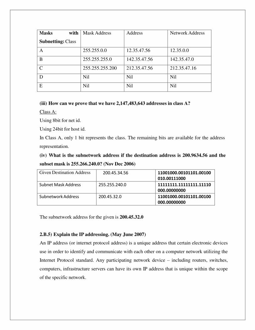
Masks with
Subnetting: Class
Mask Address Address Network Address
A 255.255.0.0 12.35.47.56 12.35.0.0
B 255.255.255.0 142.35.47.56 142.35.47.0
C 255.255.255.200 212.35.47.56 212.35.47.16
D Nil Nil Nil
E Nil Nil Nil
(iii) How can we prove that we have 2,147,483,643 addresses in class A?
Class A:
Using 8bit for net id.
Using 24bit for host id.
In Class A, only 1 bit represents the class. The remaining bits are available for the address
representation.
(iv) What is the subnetwork address if the destination address is 200.9634.56 and the
subset mask is 255.266.240.0? (Nov Dec 2006)
Given Destination Address 200.45.34.56 11001000.00101101.00100
010.00111000
Subnet Mask Address 255.255.240.0 11111111.11111111.11110
000.00000000
Subnetwork Address 200.45.32.0 11001000.00101101.00100
000.00000000
The subnetwork address for the given is 200.45.32.0
2.B.5) Explain the IP addressing. (May June 2007)
An IP address (or internet protocol address) is a unique address that certain electronic devices
use in order to identify and communicate with each other on a computer network utilizing the
Internet Protocol standard. Any participating network device – including routers, switches,
computers, infrastructure servers can have its own IP address that is unique within the scope
of the specific network.

The IP address acts as a locator for one IP device to find another and interact with it. An IP
address is not always a unique identifier due to technologies such as dynamic assignment and
network address translation.
Each IP address consists of four bytes (32 bits), defining three fields: class type, netid, and
hostid.
Class Types:
To defining a class of address, there are five different field-length patterns in use. Different
class types are designed for different types of organizations.
Class A – uses 1 byte for the class type, net id and remaining 3 bytes for host id numbers.
Class B – uses 2 bytes for the class type, net id and remaining 2 bytes for host id numbers.
Class C – uses 3 bytes for the class type, net id and remaining 1 byte for host id numbers.
Class D – reserved for multicast addresses. Multicasting allows copies of a datagram to be
passed to a select group of hosts rather than to an individual host.
Class E – Future use.
Class A network does not necessarily consist of 16 million machines on a single network,
which would excessively burden most network technologies and their administrators. Instead,
a large company is assigned a class A network, and segregates it further into smaller sub-nets
using “Classless Inter-Domain Routing”.
2.B.6) Explain Bluetooth (802.15.1) in detail
Bluetooth fills the niche of very short-range communication between mobile phones,
PDAs, notebook computers, and other personal or peripheral devices.
For example, Bluetooth can be used to connect a mobile phone to a headset, or a
notebook computer to a printer. Roughly speaking, Bluetooth is a more convenient
alternative to connecting two devices with a wire. In such applications, it is not
necessary to provide much range or bandwidth.
This is fortunate for some of the target battery-powered devices, since it is important
that they not consume much power.
Bluetooth operates in the license-exempt band at 2.45 GHz. It has a range of
onlyabout 10 m. For this reason, and because the communicating devices typically
belong toone individual or group, Bluetooth is sometimes categorized as a personal
area network(PAN).
Version 2.0 provides speeds up to 2.1 Mbps. Power consumption is low.
Bluetooth is specified by an industry consortium called the Bluetooth Special Interest
Group. It specifies an entire suite of protocols, going beyond the link layer to define
application protocols, which it calls profiles, for a range of applications. For
example,there is a profile for synchronizing a PDA with a personal computer.
Another profile gives a mobile computer access to a wired LAN in the manner of
802.11, although this was not Bluetooth• s original goal. The IEEE 802.15.1 standard
is based on Bluetooth but excludes the application protocols.
The basic Bluetooth network configuration, called a piconet, consists of a master
device and up to seven slave devices, as in Figure 2.40. Any communication is
between the master and a slave; the slaves do not communicate directly with each
other. Because slaves have a simpler role, their Bluetooth hardware and software can
be simpler and cheaper.
Since Bluetooth operates in an license-exempt band, it is required to use a spread
spectrum technique (as discussed in Section 2.1.2) to deal with possible interference
in the band. It uses frequency hopping with 79 channels (frequencies), using each for
625 μm at a time.
This provides a natural time slot for Bluetooth to use for synchronous time division
multiplexing. A frame takes up 1, 3, or 5 consecutive time slots. Only the master can
start to transmit in odd-numbered slots.
A slave can start to transmit in an even-numbered slot, but only in response to a
request from the master during the previous slot, thereby preventing any contention
between the slave devices.
A slave device can be parked: set to an inactive, low-power state. A parked device
cannot communicate on the piconet; it can only be reactivated by the master. A
piconet can have up to 255 parked devices in addition to its active slave devices.
ZigBee is a newer technology that competes with Bluetooth to some extent. Devised
by the ZigBee alliance and standardized as IEEE 802.15.4, it is designed for situations
where the bandwidth requirements are low and power consumption must be very low
to give very long battery life.
It is also intended to be simpler and cheaper than Bluetooth, making it financially
feasible to incorporate in cheaper devices such as a wall switch that wirelessly
communicates with a ceiling-mounted fan.
2.B.7) (i) How is the looping problem solved by switches and by routers. How do
switches/routers handle link failure? (Dec 12)
The looping problem solved by switches by using an algorithm named Spanning Tree
algorithm and Routers by using Dijkstra• s shortest path algorithm. Switches handle the
looping problem through making spanning tree.
Switches:
Switching handle the looping problem by building Spanning Tree.
Spanning Tree Algorithm:
There are possibilities in the extended LANs having loop like structure. Bridges and
switch must be able to correctly handle loops. This addressed by having the bridge or switch
run a distributed Spanning Tree Algorithm.
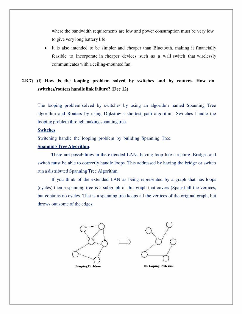
If you think of the extended LAN as being represented by a graph that has loops
(cycles) then a spanning tree is a subgraph of this graph that covers (Spans) all the vertices,
but contains no cycles. That is a spanning tree keeps all the vertices of the original graph, but
throws out some of the edges.

Consider the following extended LAN with many bridges or switch forms loops.
If we remove some ports for the bridge or switch from the topology, the extended
LAN reduced to a cyclic tree. The main idea of the spanning tree is for the bridge or switch to
select the ports over which they will forward frame. The algorithm selects ports as follows.
The spanning tree algorithm first selects the bridge with smallest id as the root of the
spanning tree as described below.
The root bridge or switch always forwards frames out over all of its ports.
Each bridge computes the shortest path to the root and records the corresponding port.
This port is also selected as the bridge or switch preferred path to the root.
All the bridge or switch connected to a given LAN elect a single designated bridge
that will be responsible for forwarding frames towards the root bridge.
2.B.8) Explain in detail about SONET (May 11)
Ans:
Description of Synchronous optical network (SONET)
Features of SONET
Architecture
SONET Layers

UNIT 3
PART A
3.A.1) What kind of routing information do routers exchange among themselves while
running distance vector algorithm? In particular, briefly describe the format of the
routing information that it exchanged. (May Jun 2007)
Ans:
In distance vector algorithm, the routers exchange their routing table with other
neighbor routers.
The routing table consist information€s on Network ID, Cost and Next Hop for the
neighbours.
3.A.2) Identify the class/speaciality of the following IP addresses:
(May 2009) a)110.34.56.45 b)127.1.1.1 c)212.208.63.23
d)255.255.255.255
a)110.34.56.45 - Class A
b)127.1.1.1 - Loop back address
c)212.208.63.23 - Class C
d)255.255.255.255 – Broadcast address
3.A.3) What is the purpose of Address Resolution Protocol(ARP)? (May 2009)
ARP is a dynamic mapping method that finds a physical address for a given logical address.
i.e. mapping IP address to physical address.
3.A.4) What is multicasting? .(Nov Dec 2010)&(Nov Dec 2011)
Ans: Multicasting is a technical term that means that you can send a piece of data (a packet)
to multiple sites at the same time. (How big a packet is depends on the protocols involved-it
may range from a few bytes to a few thousand.) The usual way of moving information around
the Internet is by using unicast protocols -- tools that send packets to one site at a time.
3.A.5) What are the different kinds of multicast routing? (May 2011)
Different kinds of multicast routing are reverse path multicasting and reverse path
broadcasting.
3.A.6) Define subnetting. (May 2011)
Subnetting is a technique that allows a network administrator to divide one physical network
into smaller logical networks and thus, control the flow of traffic for security or efficiency
reasons.
3.A.7) What is multicast? What is the motivation for developing multicast? (May
2011) Multicasting means delivering the same packet simultaneously to a group of
clients. Motivation for developing multicast is that there are applications that want to send a
packet to more than one destination hosts.
3.A.8) Expand and define MTU. (May 2012)
Maximum Transmission Unit. MTU is a networking term defines the largest packet size that
can be sent over a network connection.
3.A.9) What are the salient features of IPV6? .(Nov Dec 2012)
Ans: The following are the features of the IPv6 protocol:
New header format
Large address space
Efficient and hierarchical addressing and routing infrastructure
Stateless and stateful address configuration
Built-in security
Better support for quality of service (QoS)
New protocol for neighboring node interaction
Extensibility
3.A.10) Define source routing. (Dec 2013)
All the information about the network topology is required to switch a packet across the
network is provided by the source host. For switching that uses neither virtual circuits nor
conventional datagrams is known as source routing.
3.A.11) What is the need of subnetting? (Dec 2013)
Subnetting divides one large network into several smaller ones. Subnetting adds an
intermediate level of hierarchy in IP addressing.
PART B
3.B.1) State the major difference between Distance Vector Routing and Link State
Routing. Discuss how these routing techniques work. (Nov Dec 2006, Dec-13)
Ans: There are two major types of routing protocols: Distance Vector and Link State.
Distance Vector:
Distance Vector Protocol broadcasts its complete routing table periodically. Examples
of Distance Vector Protocols are RIP, BGP [Border Gateway Protocol], IGRP, EIGRP
[Enhanced IGRP]. A distance-vector routing protocol is one of the two major classes
of routing protocols used in packet-switched networks for computer communications,
the other major class being the link state protocol. A distance vector routing protocol
uses the Bellman-Ford algorithm to calculate paths.
Count-to-infinity problem
Issues with Distance vector routing
A distance vector routing protocol requires that a router informs its neighbours of topology
changes periodically and, in some cases, when a change is detected in the topology of a
network. The three key features for this routing is,
1.Sharing knowledge about the entire Network:
Each router sends all of its collected knowledge about the network to its neighbours.
2.Sharing only with neighbours:
Each router sends its collected knowledge about the network to its neighbour routers which
directly connected. It sends whatever it has knowledge about the network through all of its
ports.
3.Sharing at regular intervals:
Each router periodically shares its knowledge about the entire network with its neighbours.
Sharing Information: A router can share its knowledge about network to its neighbours. The
knowledge may be collected by itself or otherwise shared from other routers.

Routing Table:
Distance vector routing information may be, Network ID, cost and NextHop. These three
essentials need to form a Distance vector€s routing table.
Link State:
A Link-state routing is a concept used in routing of packet-switched networks in computer
communications. Link-state routing works by having the routers tell every router on the
network about its closest neighbours. The entire routing table is not distributed from any
router, only the part of the table containing its neighbours.
The basic concept of link-state routing is that every node constructs a map of the connectivity
of the network, in the form of graph. Using that map of connectivity graph, each node
independently calculates the best next hop from it for every possible destination in the
network. The collection of best next hops forms the Routing Table for the node.
Contrast with Distance Vector:
Distance vector, which work by having each node share its routing table with its neighbours.
But, in link state protocol, the only information passed between the nodes is information used
to construct the connectivity maps.
Note:* Optimized link state routing protocol is its extended version which is used with
wireless mesh networks.
Three Key features for this routing are:
Sharing knowledge about the neighbourhood:
Instead of sending its entire routing table, a router sends information about its
neighbourhood only.
Share to all Routers:
Each router sends its information to every other router on the network using process
named flooding.
Share the information when change:
Every router sends information about its neighbours if any change occurs.
Distributing the information for the map:
Next, each node periodically makes up a short message, the link-state advertisement, which:
Identifies the node which is producing it.
Identifies all the other nodes to which it is directly connected.
Includes a sequence number, which increases every time the source node makes up a
new version of the message. This message is then flooded throughout the network.
Calculating the shortest path:
Each node independently runs an algorithm called Dijkstra€s algorithm used to identify every
other node in the network.
3.B.2) Explain Routing table end Routing module. (Nov Dec 2007)
Routing table In Internetworking a routing table or Routing Information Base (RIB), is an
electronic table or database type object that is stored in a router or a networked computer.
The routing table stores the routes to particular network destinations. This information
contains the topology of the network immediately around it. The construction of routing
tables is the primary goal of routing protocols and static routes.
Function – During the process of routing, decisions of hosts and routers are aided by the
routing table. The routing table is not exclusive to a router. Depending on the routable
protocol, host may also have a routing table that may be used to decide the best router for the
packet to be forwarded.
Type of entries in routing table: Network Route à A route (path) to a specific Network ID
in the internetwork. Host Route à A route to a specific internetwork address (Network ID and
Host ID). Host routes allow intelligent routing decisions to be made for each network
address. Host routes are used to create custom routes to control or optimize specific types of
network traffic. Default Route à A route that is used when no other routes for the destination
are found in the routing table. If a router or end system cannot find a route for a destination,
the default route is used.
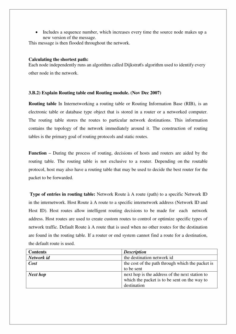
Contents Description
Network id the destination network id
Cost the cost of the path through which the packet is
to be sent
Next hop next hop is the address of the next station to
which the packet is to be sent on the way to
destination
3.B.3) Explain Link state routing.(MAY 12)
Routing protocols may use two main classes of routing protocols, Distance-Vector
Routing protocol and Link-State Routing protocol used in packet-switched networks
for computer communications. Examples of link-state routing protocols include OSPF
and IS-IS.
The link-state protocol is performed by every switching node in the network. The
basic concept of link-state routing is that every node constructs a map of the
connectivity of the network, in the form of a graph showing which nodes are
connected to which other nodes.
Each node then independently calculates the best next hop from it for every possible
destination in the network. The collection of best next hops forms the routing table for
the node.
Determining the neighbor node
First, each node needs to determine what other ports it is connected to, over fully-working
links; it does this using a simple reachability protocol which it runs separately with each of its
directly-connected neighbors.
Distributing the information for the map
Next, each node periodically makes up a short message, the link-state advertisement,which:
Identifies the node which is producing it.
Identifies all the other nodes to which it is directly connected.
Includes a sequence number, which increases every time the source node makes up a new
version of the message.
This message is then flooded throughout the network. Each node in the network remembers,
for every other node in the network, the sequence number of the last link-state message which
it received from that node. Starting with the node which originally produced the message, it
sends a copy to all of its neighbors.
When a link-state advertisement is received at a node, the node looks up the sequence number
it has stored for the source of the link-state message. If this message is newer (i.e. has a
higher sequence number), it is saved, and a copy is sent in turn to each of that node€s neighbors.
Calculating Shortest Path
Each node independently runs an algorithm over the map to determine the shortest
path from itself to every other node in the network; generally some variant of Dijkstra• s
algorithm.
Contrast with Distance-vector
Distance vector routing protocols which work by having each node share its routing table
with its neighbors. In a link-state protocol, the only information passed between the nodes is
information used to construct the connectivity maps.
Effectiveness of Link-State
Link-state routing responds faster to broken links or the addition of links. Routes can be
based on the avoidance of congested areas, the speed of a line, the cost of using a line, or
various priorities. OSPF (Open Shortest Path First) is the most common routing protocol to
use the link-state algorithm.
3.B.4)Explain the inter domain routing. (8) (Dec-12)
Unicast routing protocol: Intradomain and Interdomain
Inter domain routing:
Routing between autonomous system. E.g. path vector
Routing protocols BGP.
Protocols for interdomain routing are also called Exterior Gateway Protocols
3.B.5)Explain the RIP algorithm with a simple example of your choice. (16) (May-14,12)
RIP- Routing Information Protocol
RIP response message
RIP advertisements
Forwarding table
RIP message format:
1. Command-8 bits field
2. Version-16 bits field
3. Family-16 bits field
4. Network address
5. Distance-32 bits field
Request and Response
Timers in RIP:
1. Periodic timer(25-35sec)
2. Expiration timer(180 sec)
3. Garbage collection timer
RIPV2:
Advantages & Disadvantages
Message format
Authentication
UNIT 4
PART A
4.A.1) What are the advantages of using UDP over TCP? (Dec-10)
TCP always guarantees three things - your data reaches its destination, it reaches there in
time and it reaches there without duplication.
In TCP, since all the work is done by the operating system, so you just need to sit back
and watch the show. Even the debugging is taken care of by your OS.
It automatically breaks up data into packets for you.
It is slower in functioning than UDP
4.A.2) Give the approaches to improve the QoS. (May-11)
Fine granted approaches: Provide QoS to individual applications or flows.
Coarse granted approaches: Provide QoS to large classes of data.
4.A.3) What is TCP? (Dec-11)
The Transmission Control Protocol (TCP) is one of the two original core protocols of
the Internet protocol suite (IP) and is so common that the entire suite is often called
TCP/IP.
TCP provides a connection oriented, reliable byte stream services.
The term connection oriented means the two applications using TCP must establish a
TCP connection with each other before they can exchange data.
4.A.4) Define congestion.(Dec-11)
A state occurring in part of a network when the message traffic is so heavy that it slows down
network response time.
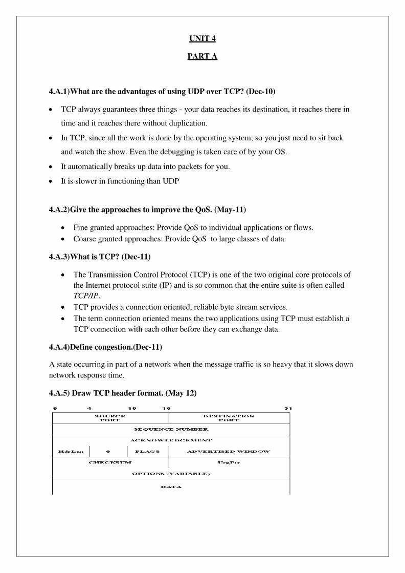
4.A.5) Draw TCP header format. (May 12)

4.A.6) Explain how TCP flow control works. (May /Jun 2007)
TCP flow control mechanism achieve using Sliding window mechanism that
generates that the receive buffer does not overflow. To avoid congestion, TCP uses
the Additive Increase and Multiple Decrease (AIMD) concepts.
The TCP sender is not allowed to send more data than the receiver can receive.
Because TCP connections are full duplex, this happens in both directions.
4.A.7) What do you mean by Qos? (May-12)
Quality of service is used in some organizations to help provide an optimal end-user
experience for audio and video communications.
QoS is most commonly used on networks where bandwidth is limited
4.A.8) Differentiate between delay and jitter. (Dec 13)
Delay: It is the time taken by a packet to travel across the network from source to destination.
Jitter: It is an unwanted variation of one or more characteristics of a periodic signal in
electronics and telecommunications. Jitter may be seen in characteristic such as the interval
between successive pulses, or the amplitude, frequency, or phase of successive cycles. Jitter
is a significant factor in the design of almost all communications links.
4.A.9) What is the difference between congestion control and flow control? (May 11)
FLOW CONTROL CONGESTION CONTROL
Done by server machine Done by router
Cannot block the bandwidth of medium Block the bandwidth of medium
Affects less on network performance Affects the network performance
Uses buffering Does not use buffering
4.A.10) Define slow
start.(May-14) Slow start: It is
congestion in TCP
4.A.11) When can application make use of UDP? (May-14)
Fast data transmission & multicast operation

PART B
4.B.1)Write a detailed note on: i) RPC ii) RTP (16) (May-11)
1.RPC: Remote Procedure Calls:
Based on client server model that is an asymmetric type of communication
RPC is implemented in the client server operation through a technique called STUB.
STUB is a procedure such as read or writes and can be defined for each server€s
client.
OSI remote procedure operations:
to the client.
It is based on two operation sending request to server and receiving the result
2.RTP: Real time Transport Protocol: Dec 13
RTP run over user datagram protocol.
Used in multimedia applications, video conferencing, music on demand, video on
demand.
Multimedia application also contains other types of data streams.All these datas are
stored into RTP library in user space along with the application.
RTP in a protocol stack and nesting:
1. Handles realtime data streams onto a single stream of UDP packets
2. No flow control and error control.
3. No acknowledgement
4. No mechanism to request to retransmissions.
5. Sequence number is given to each packet in an RTP stream
RTP header
RTP control protocol
4.B.2) What is QoS ininternetworkiog? State the techniques to improve QoS. (May June
2007)
QoS (Quality of Service) refers to a broad collection of networking technologies and
techniques.
The goal of QoS is to provide guarantees on the ability of a network to deliver predictable
results. Elements of network performance within the scope of QoS often include availability
(uptime), bandwidth (throughput), latency (delay), and error rate. QoS involves
prioritization of network traffic. QoS can be targeted at a network interface, toward a given
server or router’s performance, or in terms of specific applications. A network monitoring
system must typically be deployed as part of QoS, to insure that networks are performing at
the desired level.
QoS is especially important for the new generation of Internet applications such as VoIP
video-on-demand and other consumer services.Some core networking technologies like
Ethernet were not designed to support prioritized traffic or guaranteed of performance
levels, making it much more difficult to implement QoS solutions across the Internet.Quality
of Service is an internetworking issue that has to be defined as something a flow seeks to
attain.
Flow characteristics: (4 types)
Reliability
Delay
Jitter
Bandwidth
Technique to improve QoS:
There are many techniques used to improve the quality of service. Some common methods
are, Scheduling: Packets from different flows arrive at a switch or router for processing. A
good scheduling technique treats the different flows in a fair and appropriate manner. Some
of the scheduling techniques used to improve QoS are,
FIFO Queuing: In this queuing technique, the arrival packets are stored in First Come First
Serve basis. If the arrival rate is less than the processing rate, then the queue will fill up and
the new arriving packets will not have any space to store in the queue and gets discarded.
Priority Queuing - In priority queuing packets are first assigned to a priority class. Each
priority class has its own queue. The packets in the highest priority queue are processed first.
The packets in the lowest priority queue are processed last. This process continues until the
queue is empty.
Advantage: It provides better QoS for higher priority traffic such as multimedia that can
reach the destination with less delay.
Disadvantage: At any situation, the higher priority queue has continuous packet flow then
the lower priority queue never get a chance to process. It is called as “Starvation”.

Weighted Fair Queuing – In Weighted Fair Queuing technique, the packets are still
assigned to different classes and admitted to different queues. However, the queues are
weighted based on the priority of the queues (higher priority means a higher weight). The
system processes packets in each queue in a round robin fashion with the number of packets
selected from each queue based on the corresponding weight.
Traffic Shaping:
Traffic shaping is a mechanism to control the amount and the rate of the traffic sent to the
network. There are two techniques under this mechanism.
• Leaky Bucket – If the traffic consists of fixed size packets, the process removes a
fixed number of packets from the queues. If the traffic consists of variable length packets, the
fixed output rate must be based on the number of bytes or bits.
• Token Bucket – Leaky bucket algorithm outputs the data in average rate from the
burst data, but it does not taken the time when the host was idle, into account.
But, the Token Bucket algorithm allows idle hosts to accumulate credit for the future in the
form of tokens. For each tick of the clock, the system sends …n€ token to the bucket. The
system removes one token for every cell (or byte) of data sent.
Admission Control:
It is a mechanism used by the networking device like router and switches to accept or reject a
flow based on predefined parameters called flow specification. Before a router accepts a flow
for processing, it checks the flow specification to see if its capacity and its previous
commitments to other flows can handle the new flow.
Resource reservation:
A flow of data needs resource such as buffer bandwidth, CPU time and so on. The QoS is
improved if these resources are reserved beforehand.
4.B.3) Illustrate and explain UDP and its packet format. (Dec-11)
The User Datagram Protocol (UDP) provides a connectionless, unreliable transport service.
Connectionless means that a communication session between hosts is not established before
exchanging data. UDP is often used for communications that use broadcast or multicast
Internet Protocol (IP) packets. The UDP connectionless packet delivery service is unreliable
because it does not guarantee data packet delivery or send a notification if a packet is not
delivered. However, if a packet is delivered, a checksum is computed over the received data
and matched against the checksum transmitted in the packet. If these checksums do not
match, the received UDP packet is not handed up the stack to the next protocol layer on the
receiving side. Limitations:
Because delivery of UDP packets is not guaranteed, applications that use this protocol must
supply their own mechanisms for reliability if necessary. Although UDP appears to have
some limitations, it is useful in certain situations. UDP is efficient of its low overhead.
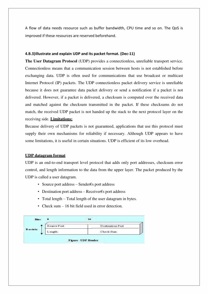
UDP datagram format
UDP is an end-to-end transport level protocol that adds only port addresses, checksum error
control, and length information to the data from the upper layer. The packet produced by the
UDP is called a user datagram.
• Source port address – Sender€s port address
• Destination port address – Receiver€s port address
• Total length – Total length of the user datagram in bytes.
• Check sum – 16 bit field used in error detection.

UDP Functionalities:
UDP provides only the basic functions needed for end-to-end delivery of a transmission. It
does not provide any sequencing or reordering functions and cannot specify the damaged
packet when reporting an error. ICMP protocol can then inform the sender that a user
datagram has been damaged and discarded and can not specify which packet has been lost.
UDP contains only a checksum; it does not contain an ID or sequencing number for a
particular data segment.
4.B.5)With neat architecture, explain TCP in detail.(16) (Dec-10)
TCP is a more sophisticated transport protocol is one that offers a reliable, connection
oriented byte stream service. Such a service has proven useful to a wide assortment of
application because it frees the application from having to worry about missing or
reordered data.
TCP guarantees the reliable in order delivery of a stream of bytes. It is a full duplex
protocol meaning that each TCP connection supports a pair of byte streams, one
flowing each direction. It also includes a flow control mechanism for each of these
byte streams that allow the receiver to limit how much data the sender can transmit at
a given time.
Finally, like UDP, TCP supports a demultiplexing mechanism that allows multiple
application programs on any given host to simultaneously carry on a conversation
with their peers. In addition to the above features, TCP also implements a highly
tuned congestion control mechanism.
END TO END ISSUES:
At the heart of TCP is sliding window algorithm. TCP supports logical connections between
processes that are running on any two computers in the internet. This means that TCP needs
an explicit connection establishment phase during which the two sides of the connection
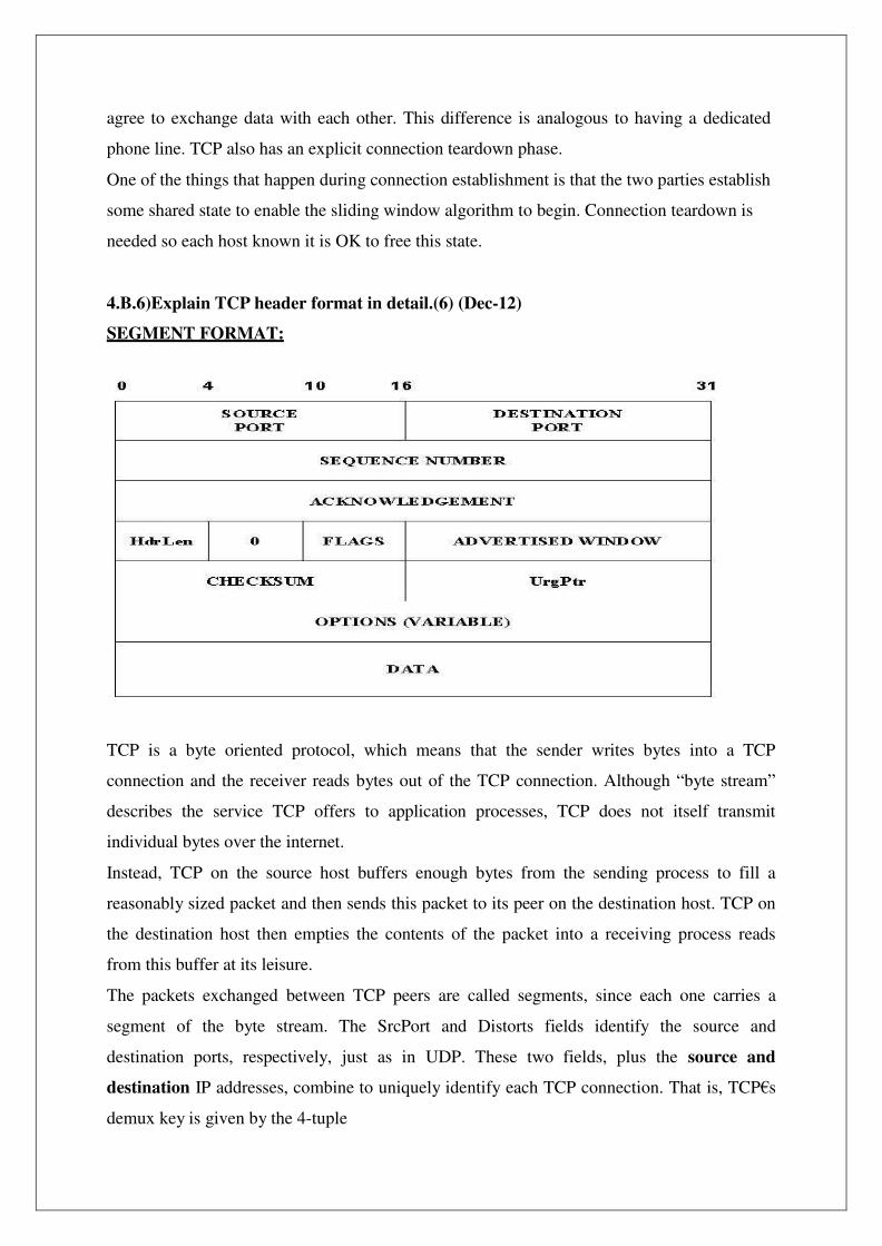
agree to exchange data with each other. This difference is analogous to having a dedicated
phone line. TCP also has an explicit connection teardown phase.
One of the things that happen during connection establishment is that the two parties establish
some shared state to enable the sliding window algorithm to begin. Connection teardown is
needed so each host known it is OK to free this state.
4.B.6)Explain TCP header format in detail.(6) (Dec-12)
SEGMENT FORMAT:
TCP is a byte oriented protocol, which means that the sender writes bytes into a TCP
connection and the receiver reads bytes out of the TCP connection. Although “byte stream”
describes the service TCP offers to application processes, TCP does not itself transmit
individual bytes over the internet.
Instead, TCP on the source host buffers enough bytes from the sending process to fill a
reasonably sized packet and then sends this packet to its peer on the destination host. TCP on
the destination host then empties the contents of the packet into a receiving process reads
from this buffer at its leisure.
The packets exchanged between TCP peers are called segments, since each one carries a
segment of the byte stream. The SrcPort and Distorts fields identify the source and
destination ports, respectively, just as in UDP. These two fields, plus the source and
destination IP addresses, combine to uniquely identify each TCP connection. That is, TCP€s
demux key is given by the 4-tuple

(SrcPort, SrclPAddr, DstPort, DstlPAddr)
The acknowledgement, sequence num and advertised window fields are all involved in
TCP€s sliding window algorithm. Because TCP is a byte oriented protocol, each byte of data
has a sequence number, the sequence numfield contains the sequence number for the first
byte of data carried in that segment. The acknowledgement and advertisement window values
flowing in the opposite direction.
The 6-bit flags field is used to relay control information between TCP peers. The possible
flags include SYN, FIN, RESET, PUSH, URG, and ACK. The SYN and FIN flags are used
when establishing and terminating a TCP connection, respectively. The ACK flag is set any
time the Acknowledgement field is valid, implying that the receiver should pay attention to it.
The URG flag signifies that this segment contains urgent data. When this flag is set, the
UrgPtr bytes into the segment. The PUSH flag signifies that the sender invoked the push
operation which indicates to the receiving side of TCP that it should notify the receiving
process of this fact.
The RESET flag signifies that the receiver has become confused for example, because it
received a segment it did not except to receive and so wants to abort the connection.
4.B.7)What is the need for Nagle€s algorithm? How does it determine when to transmit
data? (16) (Dec-10)
TCP Transmission Policy
-Nagle Algorithm
To solve the problem of congestion of WAN, the Nagle algorithm is used.
It is self-Clocking.
Faster the acks comes back,faster the data is sent
It is used by TCP implementation
TCP uses a different form of flow control called a sliding window protocol.
4.B.9)Explain any one congestion control algorithm. (6) (Dec-12)
TCP has three congestion control algorithm:
1.Additive increase
2.Slow start

3.Retransmit
Additive increase
A strategy called additive increase/multiplicative decrease regulates the number of packets
that are sent at one time. If you graphed the flow, you would see a sawtooth pattern where the
number of packets increases (additive increase) until congestion occurs and then drops off
when packets start to drop (multiplicative decrease). The window size is typically halved
when a congestion signal occurs.

UNIT 5
PART A
5.A.1) What is a Domain Name Service? .(Nov Dec 2006)
Ans: The Domain Name System (DNS) is a hierarchical distributed naming system for
computers, services, or any resource connected to the Internet or a private network. It associates
various information with domain names assigned to each of the participating entities. Most
prominently, it translates easily memorized domain names to the numerical IP addresses needed
for the purpose of locating computer services and devices worldwide. By providing a worldwide,
distributed keyword-based redirection service, the Domain Name System is an essential
component of the functionality of the Internet.
5.A.2) What is MIME? .(Nov Dec 2007)
Ans: MIME stands for Multi-purpose Internet Mail Extensions. MIME types form a standard
way of classifying file types on the Internet. Internet programs such as Web servers and browsers
A MIME type has two parts: a type and a subtype.
5.A.3) Why is DNS necessary? State it significance. (May Jun 2007)
Ans: For unique client/server identification in the network, the DNS is necessary. It provides two
addressing scheme number-based Internet Protocol addresses and test-based Domain Name
System (DNS) names. A domain name is a textual address for a location on the Internet.
5.A.4) What is Security Parameter Index? (May Jun 2007)
Ans: The Security Parameter Index (SPI) is an identification tag added to the header while using
IPsec for tunneling the IP traffic. This tag helps the kernel discern between two traffic streams
where different encryption rules and algorithms may be in use.
The SPI is an essential part of an IPsec Security Association (SA) because it enables the
receiving system to select the SA under which a received packet will be processed.
5.A.5) What are the two main categories of DNS messages? (Nov Dec 2008)
Ans: DNS has two types of messages : Query and response.
□ Query: header and question records
□ Response: Header, question records, answer records, authoritative recodrs, and
additional records.
5.A.6) How is HTTP similar to SMTP? (Nov Dec 2008)
Ans: HTTP is like SMTP because the data transferred between the client and server are similar
in appearance to SMTP messages. Also, the format of the messages is controlled by MIME-like
headers
5.A.7) What is SMTP? (Dec-10)
Ans: The protocol that supports email on the Internet is called Simple Mail Transfer Protocol.
SMTP is par tof the TCP/IP protocol suite SMTP consists of two parts: A local part and a
domain name separated by an @ sign Local Part @ Domain Name.
5.A.8) What is Telnet? (Dec-11)
Ans: Telnet is the standard TCP/IP protocol for virtual terminal service. It enables the
establishment of a connection to a remote s/m in such a way that the local terminal appears to be
a terminal at remote system.
5.A.9) State the purpose of SNMP. (Dec-11,May-12)
Ans: Simple Network Management Protocol (SNMP) is a standard internet protocol enabling
certain nodes in a network (the management stations or managing nodes) to query other network
components or applications for information about their status and activities. Such a query is
known as an SNMP poll.
5.A.10) Why email security is necessary? (Dec-11)
It is the process of using email encryption to send messages that can only be opened by the
intended recipient. Secure email encryption protects both your online data and customers
sensitive information.
5.A.11) What is SMTP? (Dec-10)
Refer 5.A.7
5.A.12) What are the advantages of allowing persistent TCP connection in HTTP? (Dec-11)
HTTP requests and responses can be pipelined on a connection
Network congestion is reduced by reducing the no. of packets caused by TCP opens.
Latency on subsequent requests is reduced
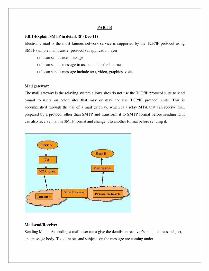
PART B
5.B.1) Explain SMTP in detail. (8) (Dec-11)
Electronic mail is the most famous network service is supported by the TCP/IP protocol using
SMTP (simple mail transfer protocol) at application layer.
□ It can send a text message
□ It can send a message to users outside the Internet
□ It can send a message include text, video, graphics, voice
Mail gateway:
The mail gateway is the relaying system allows sites do not use the TCP/IP protocol suite to send
e-mail to users on other sites that may or may not use TCP/IP protocol suite. This is
accomplished through the use of a mail gateway, which is a relay MTA that can receive mail
prepared by a protocol other than SMTP and transform it to SMTP format before sending it. It
can also receive mail in SMTP format and change it to another format before sending it.
Mail send/Receive:
Sending Mail – At sending a mail, user must give the details on receiver’s email address, subject,
and message body. To addresses and subjects on the message are coming under

header part of the mail and user’s messages are the body of the mail. At receiver side, they can
view the body of the message.
Receiving Mail – The email system periodically checks the mailbox summary, that contains
sender mail address, time of receive and the body of the message (what the sender wants to
convey).
Mail Address: SMTP addressing scheme consists of two parts:
□ Local part
□ Domain name part
Local Part addresses the mail box on the local site. Domain name addresses the name of the
destination.
Local part @ Domain Name
Local part: The local part defines the mail box, where all mails received for a user is stored for
retrieval by the user agent.
Domain name: Mail exchangers or an Organization comes at this second part. The domain name
assigned to each mail exchanger either comes from the DNS database or is a logical name.
SMTP Client / Server System both have two components,
1. User Agent (UA)
2. Mail Transfer Agent (MTA)
User Agent collects the Envelope, header, body of the message from users and sends it to Mail
Transfer Agent. The Mail Transfer Agent has the total response to transfer the message across
Internet. Both the sender and receiver have individual UA and MTA.Instead of just one MTA at
the sender site and one at the receiving site, other MTAs, acting either as client or server, can
relay the mail.
5.B.2) Explain the SMTP.Give their uses,state strengths and weakneses. (8)(Dec-10)
Refer 5.B.1

5.b.5)Discuss briefly about email(SMTP,MIMEand IMAP) (MAY-12)
SMTP (simple mail transfer protocol) at application layer.
□ It can send a text message
□ It can send a message to users outside the Internet
□ It can send a message include text, video, graphics, voice
Mail gateway:
The mail gateway is the relaying system allows sites do not use the TCP/IP protocol suite to send
e-mail to users on other sites that may or may not use TCP/IP protocol suite. This is
accomplished through the use of a mail gateway, which is a relay MTA that can receive mail
prepared by a protocol other than SMTP and transform it to SMTP format before sending it. It
can also receive mail in SMTP format and change it to another format before sending it.
SMTP Client / Server System both have two components,
1. User Agent (UA)
2. Mail Transfer Agent (MTA)
User Agent collects the Envelope, header, body of the message from users and sends it to Mail
Transfer Agent. The Mail Transfer Agent has the total response to transfer the message across
Internet.Both the sender and receiver have individual UA and MTA. Instead of just one MTA at
the sender site and one at the receiving site, other MTAs, acting either as client or server, can
relay the mail.
Mail Address:
SMTP addressing scheme consists of two parts:

□ Local part
□ Domain name part
Multipurpose Internet Mail Extensions (MIME)
MIME is a supplementary protocol that allows non-ASCII data to be sent through SMTP. MIME
is not a mail protocol and cannot replace SMTP; it is only an extension to SMTP. MIME
transforms the non-ASCII data from the sender site to NVT ASCII format and delivers it to the
client SMTP to be sent through the Internet. The server SMTP at the receiving side the NVT
ASCII data and delivers it to MIME to be transformed back to the original data.

5.B.6) Explain HTTP.Give their uses,state strengths and weakneses. (8)(Dec-10)
HTTP (Hyper Text Transfer Protocol):
The Hypertext Transfer Protocol is a protocol used mainly to access data on the World Wide
Web. The protocol can transfer data in the form of plain text, hypertext, audio, video and so on.
Its functions like the combination of FTP and SMTP. It is similar to FTP by transferring files and
uses the services of TCP. And like as SMTP by transferring the data between the client and the
server look like SMTP messages. The idea of HTTP is very simple. A client sends a request,
which looks like mail, to the server. The server sends the response, which looks like a mail reply,
to the client. The request and response messages carry data in the form of a letter with MIME
like format.
5.B.7) Discuss about World WideWeb in detail (8)(May-11)
WWW (World Wide Web):
The World Wide Web (WWW), or the web, is a repository of information spread all over the
world and linked together. The WWW has a unique combination of flexibility, portability, and
user-friendly features that distinguish it from other services provided by the Internet.
The WWW is a distributed client-server service, in which a client using a browser can access a
service using a server. However, the service provided is distributed over many locations called
web sites.
5.B.8) Explain in detail about DNS and its frame format. (16)(Dec-11)
The Internet Corporation of Assigned Names and Numbers (ICANN) is responsible for
managing and coordinating the DNS. The DNS top level name space is divided into 2 broad
categories,
1. General Top Level Domain (GTLD)
The general top level domain defines registered hosts according to their generic behavior that are
represented using three character labels in their first level.
Examples:
Domain name- Usage-Descriptions
.com-Commercial use.
.edu-Educational use.
.gov-Government use.
.int-International Organization use.
.m il-Military use.
.net-Network support use.
.org-Non profit Organization use.
2. Country-Code Top Level Domain (CCTLD): CCTLD have been typically assigned to
national or regional registries. To further Classify and divide the name space, some national
registry have created sub domains under the country codeTLDs. Example: In Singapore, SGNIC
is the authority that administers the name space for the .SG domain. The .SG domain is further
sub divided to com.sg, net.sg, org.sg, gov.sg and edu.sg. *.sg is the CCTLD type domain
name.Another third type domain’s also represented, that is given below
3. Inverse Domain:It is used to map an address to a name. The query to the inverse DNS server
is called as pointer or inverse query that contains only the IP address. The inverse domain is
added to the domain name space with the first level node called arpa And the second level node
in-addr followed by the IP address.
Domain Name Space
The Internet Domain Name System (DNS) is a set of distributed databases containing IP
addresses and their corresponding domain names. Each domain name is mapped to a particular
numeric address. DNS, with servers located all over the Internet, performs the translation back
and forth between names and numbers. This scheme enables users to invoke an easy-to-
remember name instead of a more mysterious string of numbers (e.g. 160.96.7.25) when using
the Internet. In the beginning, the original set of machine names used throughout the Internet
formed a flat name space. Hence, a hierarchical naming scheme is used and the name system is
decentralized by delegating authority for parts of the namespace and distributing responsibility
for the mapping between names and addresses.
Valid Domain Names
Domain names can only contain alphabets, numbers and dashes (i.e. hyphens or the minus
signs). The underscore character, “_”, is an invalid character. SGNIC Authority will
reject applications for domain names containing invalid characters. Each field in the
domain name should be less than sixty three characters long.
5.B.9) Write short notes on FTP.
(8)(May-14) FTP (File Transfer
Protocol)
It is standard mechanism provided by TCP/IP for copying a file from one host to
another. Transferring files from one computer to another is one of the most common
tasks expected from a networking or internetworking environment.
FTP differs from other client-server applications in that it establishes two connections
between the hosts. One connection is used for data transfer, the other for control
information (commands and responses). Separation of commands and data transfer
makes FTP more efficient. The control connection uses very simple rules of
communication.