department of electrical and electronics engineering...project management and finance: demonstrate...
TRANSCRIPT
Page 1 of 42
Department of Electrical and Electronics Engineering Birla Institute of Technology, Mesra, Ranchi - 835215 (India)
Institute Vision
To become a Globally Recognized Academic Institution in consonance with the social,
economic and ecological environment, striving continuously for excellence in education,
research and technological service to the National needs.
Institute Mission
• To educate students at Undergraduate, Post Graduate, Doctoral and Post-Doctoral levels
to perform challenging engineering and managerial jobs in industry.
• To provide excellent research and development facilities to take up Ph.D. programmes
and research projects.
• To develop effective teaching and learning skills and state of art research potential of the
faculty.
• To build national capabilities in technology, education and research in emerging areas.
• To provide excellent technological services to satisfy the requirements of the industry and
overall academic needs of society.
Department Vision
To become an internationally recognized centre of excellence in academics, research and
technological services in the area of Electrical and Electronics Engineering and related
inter-disciplinary fields.
Department Mission
• Imparting strong fundamental concepts to students and motivate them to find innovative
solutions to engineering problems independently
• Developing engineers with managerial attributes capable of applying latest technology
with responsibility
• Creation of congenial atmosphere and excellent research facilities for undertaking quality
research by faculty and students
• To strive for more internationally recognized publication of research papers, books and to
obtain patent and copyrights
• To provide excellent technological services to industry
Page 2 of 42
Program Educational Objectives (PEO)
1. To develop capability to understand the fundamentals of Science and Electrical &
Electronics Engineering for analysing the engineering problems with futuristic approach.
2. To foster a confident and competent graduate capable to solve real life practical
engineering problems
fulfilling the obligation towards society.
3. To inculcate an attitude for identifying and undertaking developmental work both in
industry as well as in academic environment with emphasis on continuous learning
enabling to excel in competitive participations at global level.
4. To nurture and nourish effective communication and interpersonal skill to work in a team
with a sense of ethics and moral responsibility for achieving goal.
Program Outcomes (PO)
A graduate shall
a) Be competent in applying basic knowledge of science and engineering for the purpose of
obtaining solution to a multi-disciplinary problem
b) Gain skilful knowledge of complex engineering problem analysis
c) Be able to design system components and processes meeting all applicable rules and
regulations
d) Be proficient in arriving at innovative solution to a problem with due considerations to
society and environment
e) Be capable of undertaking suitable experiments/research methods while solving an
engineering problem and would arrive at valid conclusions based on appropriate
interpretations of data and experimental results
f) Continually upgrade his/her understanding and become masterly at modern engineering
and soft tools and apply them along with other appropriate techniques and resources
g) Exhibit understanding of societal and environmental issues (health, legal, safety, cultural
etc) relevant to professional engineering practice and demonstrate through actions, the
need for sustainable development
h) Be committed to professional ethics, responsibilities and economic, environmental,
societal, and political norms.
i) Demonstrate appropriate inter-personal skills to function effectively as an individual, as a
member or as a leader of a team and in a multi-disciplinary setting
j) Be able to comprehend and write effective reports and design documentations; give and
receive clear instructions; make effective presentations and communicate effectively and
convincingly on complex engineering issues with engineering community and with
society at large.
k) Be conscious of financial aspects of all professional activities and shall be able to
undertake projects with appropriate management control and control on cost and time.
l) Recognize the need for continuous learning and will prepare himself/ herself
appropriately for his/her all-round development throughout the professional career.

Page 3 of 42
Graduate Attributes
1. Engineering Knowledge: Apply knowledge of mathematics, science, engineering
fundamentals and an engineering specialization to the solution of complex engineering
problems.
2. Problem Analysis: Identify, formulate, research literature and analyze complex
engineering problems
reaching substantiated conclusions using first principles of mathematics, natural sciences
and engineering sciences.
3. Design/ Development of Solutions: Design solutions for complex engineering problems
and design system components or processes that meet specified needs with appropriate
consideration for public health and safety, cultural, societal and environmental
considerations.
4. Conduct investigations of complex problems using research-based knowledge and
research methods including design of experiments, analysis and interpretation of data and
synthesis of information to provide valid conclusions.
5. Modern Tool Usage: Create, select and apply appropriate techniques, resources and
modern engineering and IT tools including prediction and modelling to complex
engineering activities with an understanding of the limitations.
6. The Engineer and Society: Apply reasoning informed by contextual knowledge to
assess societal, health, safety, legal and cultural issues and the consequent responsibilities
relevant to professional engineering practice.
7. Environment and Sustainability: Understand the impact of professional engineering
solutions in societal and environmental contexts and demonstrate knowledge of and need
for sustainable development.
8. Ethics: Apply ethical principles and commit to professional ethics and responsibilities
and norms of
engineering practice.
9. Individual and Team Work: Function effectively as an individual, and as a member or
leader in diverse teams and in multi-disciplinary settings.
10. Communication: Communicate effectively on complex engineering activities with the
engineering
community and with society at large, such as being able to comprehend and write
effective reports and design documentation, make effective presentations and give and
receive clear instructions.
11. Project Management and Finance: Demonstrate knowledge and understanding of
engineering and
management principles and apply these to one’s own work, as a member and leader in a
team, to manage projects and in multidisciplinary environments.
12. Life-long Learning: Recognize the need for and have the preparation and ability to
engage in independent and life- long learning in the broadest context of technological
change.

Page 4 of 42
COURSE INFORMATION SHEET Course code: EE 201
Course title: Electrical Measurement and Instrumentation
Pre-requisite(s): Basic knowledge of Mathematics, Basic knowledge of Natural and Engineering Physics, Basic
knowledge of Electrical circuits, Basic knowledge of Laplace transform, Basic knowledge of digital electronics and
communication
Co- requisite(s):
Credits: L: 3 T: 0 P: 0
Class schedule per week:
Class: B. Tech
Semester / Level: IV
Branch: EEE
Name of Teacher:
Course Objectives
This course enables the students:
A. To outline the students an idea of calibration, standards, different errors, static and dynamic
performance characteristics.
B. To explain the operating principle of different analog and digital instruments used for electrical
parameter measurement
C. To classify and outline the operation and construction of various a.c. and d.c. bridges for measurement
and display devices.
D. To state the basic principle of commonly available transducers and their uses for measuring different
electrical or non-electrical variables.
Course Outcomes
After the completion of this course, students will be:
1. Identify and analyse errors and state the static and dynamic characteristics of instruments.
2. Explain the working of different analog instruments (PMMC, Moving iron,
electrodynamometer type) and their use for measuring voltage, current, power, phase and
frequency.
3. Show how to balance and design different bridge networks to find the value of unknown
components.
4. State the working of digital instruments, display devices and recorders.
5. Reproduce the different working principles of transducers and also design transducers for
measurement of non-electrical quantities.
Syllabus: EE 201 ELECTRICAL MEASUREMENT AND INSTRUMENTATION
Module – I
Introduction: Definition of measurement, Generalized input-output configuration of measuring instruments and
instrumentation systems. Performance characteristics (static and dynamic), Accuracy, Precision, Types of error,
Statistical analysis, Standards of measurement. Systems of units. Fundamental and derived units. Dimensions. (5)
Module – II
Instruments: Basic requirement of a measuring instrument. Introduction to D’ Arsonval galvanometer,
Construction and principle of Moving coil, Moving iron, Induction types of instruments, Measurement of voltage,
current and power, phase, frequency, Range extension including current and potential transformers. Digital
voltmeter, vector voltmeter, Vector Impedance meter and Q-meter. (10)

Page 5 of 42
Module – III
Bridge: DC bridges for measurement of resistance Wheatstone bridges, Kelvin's double bridges and AC bridges for
measurement of L, R, C & M, Maxwell's bridges, Anderson's bridges, Wien’s bridges. Measurement of frequency,
localization of cable fault. Potentiometers: DC and AC potentiometers, Principles, Standardization and application.
(9)
Module – IV
Oscilloscopes: CRT, Construction, Basic CRO circuits, Block diagram of a modern oscilloscope, Y-amplifiers, X-
amplifiers, Triggering, Oscilloscopic measurement. Special CRO's: Dual trace, Dual beam, Sampling oscilloscope,
Storage CROs. Display Devices & Recorders: Digital display, LED, LCD, Strip chart recorder, X-Y recorder. (10)
Module – V
Transducers: Classification, Inductive, Resistive and Capacitive transducers, Analog and Digital Transducers with
applications. Hall effect, Piezo Electric, Photovoltaic transducer. Measurement of temperature and pressure. (6)
Text books:
1.Helfrick and Cooper - Modern Electronics Instrumentation and Measurement, Pearson Education, New Delhi.
2. Sawhney A.K. - Electrical & Electronic Measurement and Instrumentation, Dhanpat Rai & Son’s
Reference books:
1. Patranabis D – Sensors and Transducers, Wheeler, 1996.
2. Kalsi - Electronics Instrumentation, TMH Publication, New Delhi.
3. Deoblin – Measurement Systems.
4. Patranabis D – Principles of Industrial Instrumentation, TMH Publication, New Delhi, 1976.
5. Golding- Electrical Measurement, Wheeler Publication.
Gaps in the syllabus (to meet Industry/Profession requirements): Signal generators and signal analysers, Data
acquisition system.
POs met through Gaps in the Syllabus: a,b, c,e, f, i, j, k,l
Topics beyond syllabus/Advanced topics/Design: Process Measurement and Control
POs met through Topics beyond syllabus/Advanced topics/Design: a, b, c, e, i, j, k, l
Course Delivery methods
Lecture by use of boards/LCD projectors/OHP projectors
Tutorials/Assignments
Seminars
Mini projects/Projects
Laboratory experiments/teaching aids
Industrial/guest lectures
Industrial visits/in-plant training
Self- learning such as use of NPTEL materials and internets
Simulation
Page 6 of 42
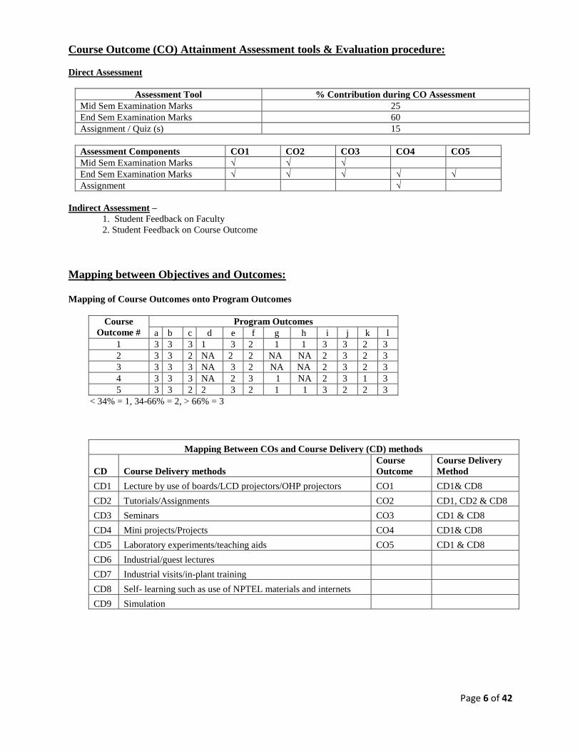
Course Outcome (CO) Attainment Assessment tools & Evaluation procedure:
Direct Assessment
Assessment Tool % Contribution during CO Assessment
Mid Sem Examination Marks 25
End Sem Examination Marks 60
Assignment / Quiz (s) 15
Assessment Components CO1 CO2 CO3 CO4 CO5
Mid Sem Examination Marks √ √ √
End Sem Examination Marks √ √ √ √ √
Assignment √
Indirect Assessment –
1. Student Feedback on Faculty
2. Student Feedback on Course Outcome
Mapping between Objectives and Outcomes:
Mapping of Course Outcomes onto Program Outcomes
Course
Outcome #
Program Outcomes
a b c d e f g h i j k l
1 3 3 3 1 3 2 1 1 3 3 2 3
2 3 3 2 NA 2 2 NA NA 2 3 2 3
3 3 3 3 NA 3 2 NA NA 2 3 2 3
4 3 3 3 NA 2 3 1 NA 2 3 1 3
5 3 3 2 2 3 2 1 1 3 2 2 3
< 34% = 1, 34-66% = 2, > 66% = 3
Mapping Between COs and Course Delivery (CD) methods
CD Course Delivery methods
Course
Outcome
Course Delivery
Method
CD1 Lecture by use of boards/LCD projectors/OHP projectors CO1 CD1& CD8
CD2 Tutorials/Assignments CO2 CD1, CD2 & CD8
CD3 Seminars CO3 CD1 & CD8
CD4 Mini projects/Projects CO4 CD1& CD8
CD5 Laboratory experiments/teaching aids CO5 CD1 & CD8
CD6 Industrial/guest lectures
CD7 Industrial visits/in-plant training
CD8 Self- learning such as use of NPTEL materials and internets
CD9 Simulation

Page 7 of 42
COURSE INFORMATION SHEET Course code: EE 203
Course title: Electric Energy Generation and Control
Pre-requisite(s): Basic knowledge about working of alternator and electric power systems
Co- requisite(s):
Credits: L: 3 T: 0 P: 0
Class schedule per week: 3 Classes per week
Class: B. Tech
Semester / Level: III
Branch: EEE
Name of Teacher:
Course Objectives
This course enables the students:
A. To enumerate the energy generation scenario and understand the principle of operation of different
types of power generation systems.
B. To relate the structure and principles of the controls related to electrical power generating stations.
C. To outline power generation from renewable energy sources and assess impact of such non-polluting
energy conversion systems.
D. To compare salient features of different generating stations and substantiate sustainable and economic
generation.
Course Outcomes:
After the completion of this course, students will be able to:
1. Outline the significance of various components of the power generation plants and explain the
principle of their operation for bulk energy generation.
2. Apply the basic knowledge of electric power generation as well as control related to real and reactive
power for load-frequency and voltage control.
3. Outline the significance of Nuclear and Diesel power plants.
4. Contrast and choose non-conventional energy sources for sustainable energy generation.
5. Assess and integrate different power generation systems for interconnected operation.
Syllabus:
Module – I: Overview of Power Generation Scenario and Thermal Power Stations
Overview of power generation scenario from thermal, hydro and nuclear and non-conventional sources. Selection of site
for a thermal station, layout, main components, boiler, economizer, air preheater, super heater, reheater, condenser, feed
heater, cooling powers, FD and ID fans, Coal handling plant, water treatment plant, Ash handling plant, Types of boilers
and theirs characteristics, Steam turbines, and their characteristics, governing system for thermal stations.
Module – II: Hydro Electric Stations
Selection of site, layout, classification of hydro plants, general arrangement and operation of a hydro - plant, governing
system for hydel plant, types of turbines.
Module – III: Nuclear Power Station
Nuclear reaction for nuclear power, nuclear fuels, feasibility of a nuclear power station, layout, main part of a nuclear
station, nuclear reactor classification, control system for nuclear power station, Safety of nuclear power reactor.
Module – IV: Diesel Electric Station
Site selection, layout, main components, choice and characteristics of diesel engines, diesel engines, diesel plant
efficiency and heat balance, maintenance.

Page 8 of 42
Module – V: Non-conventional Sources of Energy
Solar: Operating principles. Photovoltaic cell concepts. Cell, module, array. Series and parallel connections. Maximum
power point tracking, Wind: Operating principles, types of wind turbines, Bio-Mass, Tidal.
TEXT BOOKS:
• Power Plant Engineering - PK Nag TMH publications, 2nd Edition.
• A Textbook on Power System Engg. – A Chakravarti, ML Soni, PV Gupta and U.S. Bhatnagar, Dhanpat
Rai & Co., New Delhi, 2nd Edition.
REFERENCE BOOKS:
• Elements of Electrical Power Station Design-MV Deshpande, Pitman and Sons Ltd.
• Electric Power Generation, Transmission and Distribution - S.M. Singh, Prentice Hall of India, Delhi.
• Generation, Distribution and Utilization of Electrical Power – C.L. Wadhwa, New Age Publications
Course Evaluation: Individual assignment, Seminar before a committee, Theory (Quiz and End semester)
examinations
Gaps in the syllabus (to meet Industry/Profession requirements):
POs met through Gaps in the Syllabus:
Topics beyond syllabus/Advanced topics/Design:
POs met through Topics beyond syllabus/Advanced topics/Design:
Course Outcome (CO) Attainment Assessment tools & Evaluation procedure:
Direct Assessment
Assessment Tool % Contribution during CO Assessment
Mid Semester Examination 25
End Semester Examination 50
Quiz (s) 10+10
Assignment 5
Assessment Components CO1 CO2 CO3 CO4 CO5
Mid Semester Examination √ √ √
End Semester Examination √ √ √ √ √
Quiz (s) √ √ √ √ √
Assignment √ √ √ √ √
Indirect Assessment –
1. Student Feedback on Course Outcome

Page 9 of 42
Mapping of Course Outcomes onto Program Outcomes
Course
Outcome
Program Outcomes
1 2 3 4 5 6 7 8 9 10 11 12
CO1 3 3 3 1 3 1 1 1 2
CO2 3 3 3 1 3 1 1 1 2
CO3 3 3 3 3 3 1 2 2 1 1 2
CO4 3 3 3 1 3 1 1 1 1 2
CO5 3 3 3 3 3 1 1 1 1 1 1 2
3= High, 2=Medium, 1=Low
Course Delivery Methods:
CD Course Delivery methods
CD1 Lecture by use of boards/LCD projectors/OHP projectors
CD2 Tutorials/Assignments
CD3 Seminars
CD4 Industrial visits/in-plant training
CD5 Self- learning such as use of NPTEL materials and internets
CD6 Simulation
MAPPING BETWEEN COURSE OUTCOMES AND COURSE DELIVERY METHOD
Mapping Between COs and Course Delivery (CD) methods
Course Outcome Course Delivery Method
CO1 CD1, CD2, CD3, CD5
CO2 CD1, CD2, CD3, CD5
CO3 CD1, CD2, CD3, CD5
CO4 CD1, CD2, CD3, CD5
CO5 CD1, CD2, CD3, CD5

Page 10 of 42
COURSE INFORMATION SHEET Course code: EC203
Course title: Digital System Design
Pre-requisite(s): Basics of Electronics & Communication Engineering
Co- requisite(s):
Credits: L: 3 T:0 P:0 C:3
Class schedule per week: 3
Class: B. Tech
Semester / Level: III/02
Branch: ECE
Name of Teacher:
Course Objectives
This course enables the students to:
1. Understand the basics of the digital electronics.
2. Apply the knowledge of digital electronics to construct various digital circuits.
3. Analyse the characteristics and explain the outputs of digital circuits.
4. Evaluate and asses the application of the digital circuits.
5. Design digital machine for simple computing and control.
Course Outcomes
After the completion of this course, students will be able to:
CO1 Explain the concept of digital electronics.
CO2 Apply the knowledge to produce digital electronics circuits.
CO3 Analyse and categorize digital circuits.
CO4 Justify the uses of different digital circuits.
CO5 Schematize and demonstrate simple computing machines.
SYLLABUS:
Module – 1:
Basics of Digital Electronics: Number representation, Binary number system, Number base conversion, Octal,
Hexadecimal and BCD codes, binary Arithmetic, Logic gates, Introduction to VHDL and Verilog, VHDL Models,
Logic Families: TTL, ECL, and CMOS Logic Circuits, Logic levels, voltages and currents, fan-in, fan-out, speed,
power dissipation. Comparison of logic families.
Module – 2:
Simplification of Boolean functions: Boolean Algebra, Basic theorems and Properties, De Morgan’s theorem,
Canonical & Standard forms, Simplification of Boolean function using Karnaugh map, POS & SOP simplification,
Prime implicant, NAND and NOR implementation.
Module – 3:
Design of Combinational Circuits: Analysis and design procedure, Parity Generators and Checkers, Adders,
Subtractors, Look ahead carry, Adder, 4-bit BCD adder/subtractor, Magnitude comparator, Decoders, Encoders,
Multiplexers, De-multiplexers, , Design of 1 bit ALU for basic logic and arithmetic operations.
Module – 4:
Design of Sequential Circuits and Memories: Basic Latch, Flip-Flops (SR, D, JK, T and Master-Slave),
Triggering of Flip Flops, Synchronous and asynchronous counters, Registers, Shift Registers, Memories and
Programmable Logic design, Types of memories, Memory Expansion and its decoding, Programmable Logic Arrays
(PLA), Programmable Array Logic (PAL)

Page 11 of 42
Module – 5:
Design of simple computing machines: SAP-I concepts with stress on timing diagrams, Microinstructions, Fetch
and Execution cycle variable machine cycle, Hardware control Matrix, Macroinstructions, Microprogramming, Bus
concepts, Multiplexed Minimum system. Pipelining concepts.
Books recommended:
Textbooks:
1. “Digital Design”, Morris Mano and Michael D. Ciletti ,5th edition PHI
2. “Digital System Design using VHDL”, Charles H Roth, Thomson Learning
Reference books:
1. Digital computer Electronics AP Malvino, 3rd Edition Mc Graw Hill
Gaps in the syllabus (to meet Industry/Profession requirements): Hands-on-practical on microprocessor trainer
Kit
POs met through Gaps in the Syllabus: N/A
Topics beyond syllabus/Advanced topics/Design: N/A
POs met through Topics beyond syllabus/Advanced topics/Design: N/A
Course Outcome (CO) Attainment Assessment Tools and Evaluation Procedure
Direct Assessment
Assessment Tools % Contribution during CO Assessment
Continuous Internal Assessment 50
Semester End Examination 50
Continuous Internal Assessment % Distribution
Mid semester examination 25
Two quizzes 20 (2×10)
Teacher’s Assessment 5
Assessment Components CO1 CO2 CO3 CO4 CO5
Continuous Internal Assessment
Semester End Examination
Indirect Assessment
1. Student Feedback on Faculty
2. Student Feedback on Course
Course Delivery Methods
CD1 Lecture by use of boards/LCD projectors/OHP projectors
CD2 Assignments
CD3 Laboratory experiments/Teaching aids/Seminars
CD4 Mini Projects
CD5 Industrial visits/in-plant training
CD6 Self- learning such as use of NPTEL materials and internets
CD7 Simulation

Page 12 of 42
Mapping between Course Outcomes and Program Outcomes
CO PO1 PO2 PO3 PO4 PO5 PO6 PO7 PO8 PO9 PO10 PO11 PO12
CO1 3 3 2 3 3 1 1 3 3
CO2 3 3 2 3 3 3 2 3 3
CO3 3 3 2 3 3 3 2 3 3
CO4 3 3 2 3 3 2 2 3 3
CO5 3 3 2 3 3 2 2 3 3
< 34% = 1, 34-66% = 2, > 66% = 3
Mapping between Course Outcomes and Course Delivery Method
Course Outcomes Course Delivery Method
CO1 CD1, CD2, CD3, CD6, CD7
CO2 CD1, CD2, CD3, CD6, CD7
CO3 CD1, CD2, CD3, CD6, CD7
CO4 CD1, CD2, CD3, CD6, CD7
CO5 CD1, CD2, CD3, CD6, CD7

Page 13 of 42
COURSE INFORMATION SHEET Course code: EE205
Course title: CIRCUIT THEORY
Pre-requisite(s): Basics of Electrical Engineering
Co- requisite(s): Mathematics
Credits: 4 L:3 T:1 P:0
Class schedule per week: 04
Class: B. Tech
Semester / Level: 02
Branch: EEE
Name of Teacher:
Course Objectives:
This course enables the students to:
A. list the Properties and discuss the concepts of graph theory
B. solve problems related to network theorems
C. illustrate and outline the Multi- terminal network in engineering
D. select and design of filters
Course Outcomes:
After the completion of this course, students will:
1. be able to solve problems related to DC and AC circuits
2. become adept at interpreting network analysis techniques
3. be able to determine response of circuits consisting of dependent sources
4. analyse linear and non-linear circuits
5. be able to design the filters with help of electrical element
Syllabus:
Module – I
Network Topology: Definition and properties, Matrices of Graph, Network Equations &Solutions: Node and Mesh
transformation; Generalized element; Source transformation; Formulation of network equations; Network with
controlled sources; Transform networks; Properties of network matrices; Solution of equations; Linear time-
invariant networks; Evaluation of initial conditions; Frequency and impedance scaling.
Module – II
Network Theorem: Substitution theorem, Tellegen's theorem, Reciprocity theorem; State space concept and State
variable modelling.
Module – III
Multi-terminal Networks: Network function, transform networks, natural frequency (OCNF and SCNF); Two-port
parameters, Equivalent networks.
Module – IV
Elements of Network Synthesis: Positive real function, Reactance functions, RC functions,
RL Network, Two-port functions, Minimum phase networks.
Module – V
Approximation: Filter specifications; Butterworth approximation; Chebyshev approximation; Frequency
transformation; High pass; Band pass; all pass and notch filter approximation.
Text Books:
1. V.K. Aatre, Network Theory & Filter Design, New Age International Pvt. Ltd., New Delhi. (T1)
2. M.S. Sukhija, T.K.Nagsarkar, Circuits and Networks, Oxford University Press, 2nd ed., New Delhi.(T2)

Page 14 of 42
Reference Books:
1. M.E. Van Valkenberg, Introduction to Modern Network Synthesis, John Wiley & Sons (1 January 1966) (R1)
2. Balabanian, N. and T.A. Bickart, “Electric Network Theory”, John Wiley & Sons, New York, 1969. (R2)
3. C. L. Wadhwa, Network Analysis and Synthesis, New Age International Pvt. Ltd., New Delhi(R2)
Gaps in the syllabus (to meet Industry/Profession requirements):
i. Practical aspects and demonstration of electrical and non-electrical systems
POs met through Gaps in the Syllabus:
a) Demonstrate appropriate inter-personal skills to function effectively as an individual, as a member or as a
leader of a team and in a multi-disciplinary setting (POi)
b) Be able to comprehend and write effective reports and design documentations; give and receive clear
instructions; make effective presentations and communicate effectively and convincingly on complex
engineering issues with engineering community and with society at large. (POj)
c) Be conscious of financial aspects of all professional activities and shall be able to undertake projects with
appropriate management control and control on cost and time. (POk)
d) Recognize the need for continuous learning and will prepare himself/ herself appropriately for his/her all-
round development throughout the professional career. (POl)
Topics beyond syllabus/Advanced topics/Design:
i. Design of filter using operational amplifier
POs met through Topics beyond syllabus/Advanced topics/Design:
Course Delivery methods
Lecture by use of boards/LCD projectors/OHP projectors
Tutorials/Assignments
Seminars
Mini projects/Projects
Laboratory experiments/teaching aids
Industrial/guest lectures
Industrial visits/in-plant training
Self- learning such as use of NPTEL materials and internets
Simulation
Course Outcome (CO) Attainment Assessment tools & Evaluation procedure:
Direct Assessment
Assessment Tool % Contribution during CO Assessment
Mid Sem Examination Marks 25
End SemExamination Marks 50
Assignment 05
Quiz (s) 20
Assessment Compoents CO1 CO2 CO3 CO4 CO5
Mid Sem Examination Marks √ √ √
End Sem Examination Marks √ √ √ √ √
Assignment √ √
Indirect Assessment –
1. Student Feedback on Faculty
2. Student Feedback on Course Outcome
Page 15 of 42
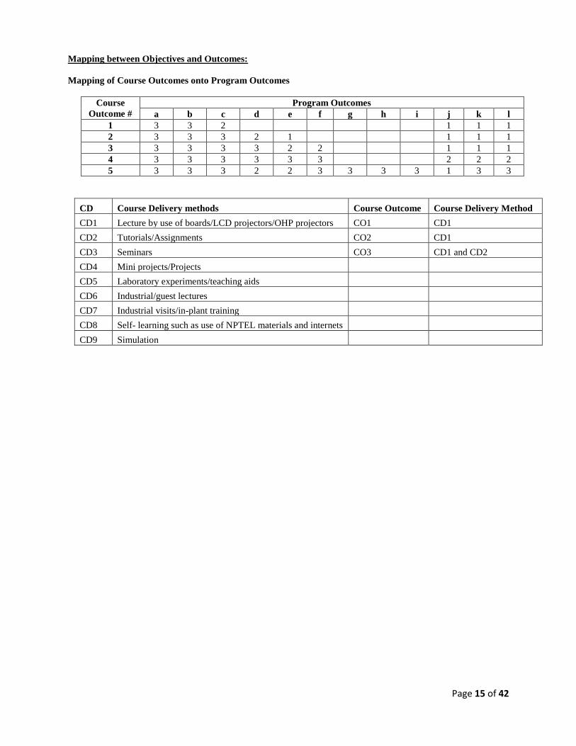
Mapping between Objectives and Outcomes:
Mapping of Course Outcomes onto Program Outcomes
Course
Outcome #
Program Outcomes
a b c d e f g h i j k l
1 3 3 2 1 1 1
2 3 3 3 2 1 1 1 1
3 3 3 3 3 2 2 1 1 1
4 3 3 3 3 3 3 2 2 2
5 3 3 3 2 2 3 3 3 3 1 3 3
CD Course Delivery methods Course Outcome Course Delivery Method
CD1 Lecture by use of boards/LCD projectors/OHP projectors CO1 CD1
CD2 Tutorials/Assignments CO2 CD1
CD3 Seminars CO3 CD1 and CD2
CD4 Mini projects/Projects
CD5 Laboratory experiments/teaching aids
CD6 Industrial/guest lectures
CD7 Industrial visits/in-plant training
CD8 Self- learning such as use of NPTEL materials and internets
CD9 Simulation

Page 16 of 42
COURSE INFORMATION SHEET
Course code: EE102
Course title: ELECTRICAL ENGINEERING LABORATORY
Pre-requisite(s): Physics, Fundamentals of Mathematics and Electrical Engineering.
Credits: L T P
0 0 3
Class schedule per week: 3
Course Overview: Concepts of measuring instruments, AC RLC series parallel circuit operation, resonance, KVL
and KCL, circuit theorems, 3-phase star and delta connections, measurement of low and high resistance of D.C.
machine, measurement of power by three voltmeter, three-ammeter methods, measurement of power of 3-phase
induction motor by two-wattmeter method.
Course Objectives
This course enables the students:
A. To describe student’s practical knowledge of active and passive elements and operation of measuring
instruments
B. To demonstrate electrical circuit fundamentals and their equivalent circuit models for both 1-φ and 3-
φ circuits and use circuit theorems
C. To establish voltage & current relationships with the help of phasors and correlate them to
experimental results
D. 1. To conclude performance of 1 – Ф AC series circuits by resonance phenomena
2. To evaluate different power measurement for both 1-φ and 3- φ circuits
Course Outcomes
After the completion of this course, students will be able to:
1. classify active and passive elements, explain working and use of electrical components, different types
of measuring instruments;
2. illustrate fundamentals of operation of DC circuits, 1-φ and 3- φ circuits and also correlate the
principles of DC, AC 1-φ and 3- φ circuits to rotating machines like Induction motor and D.C
machine.;
3. measure voltage, current, power, for DC and AC circuits and also represent them in phasor notations;
4. analyse response of a circuit and calculate unknown circuit parameters;
5. recommend and justify power factor improvement method in order to save electrical energy.
LIST OF EXPERIMENTS:
1. Name: Measurement of low & high resistance of DC shunt motor
Aim: (i) To measure low resistance of armature winding of DC shunt motor
(ii) To measure high resistance of shunt field winding of DC shunt motor
2. Name: AC series circuit
Aim: (i) To obtain current & voltage distribution in AC RLC series circuit and to draw phasor diagram
(ii) To obtain power & power factor of single-phase load using 3- Voltmeter method and to draw
phasor diagram
3. Name: AC parallel circuit
Aim: (i) To obtain current & voltage distribution in AC RLC parallel circuit and to draw phasor diagram
(ii) To obtain power & power factor of single-phase load using 3- Ammeter method and to draw
phasor diagram
4. Name: Resonance in AC RLC series circuit
Aim: (i) To obtain the condition of resonance in AC RLC series circuit
(ii) To draw phasor diagram

Page 17 of 42
5. Name: 3 phase Star connection
Aim: (i) To establish the relation between line & phase quantity in 3 phase star connection
(ii) To draw the phasor diagram
6. Name: 3 phase Delta connection
Aim: (i) To establish the relation between line & phase quantity in 3 phase delta connection
(ii) To draw phasor diagram
7. Name: 3 phase power measurement
Aim: (i) To measure the power input to a 3-phase induction motor using 2 wattmeter method
(ii) To draw phasor diagram
8. Name: Self & mutual inductance
Aim: To determine self & mutual inductance of coils
9. Name: Verification of Superposition, Thevenin’s and Reciprocity theorem
Aim: (i) To verify Superposition theorem for a given circuit
(ii) To verify Thevenin’s theorem for a given circuit
10. Name: Verification of Norton’s, Tellegen’s and Maximum Power transfer theorem
Aim: (i) To verify Norton’s theorem for a given circuit
(ii) To verify Maximum Power transfer theorem for a given circuit
Gaps in the syllabus (to meet Industry/Profession requirements)
1. Application of principles of magnetic circuits to electrical machines like transformers, generators and
motors
2. Visualize Phase sequence
POs met through Gaps in the Syllabus: a, b, c, g
Topics beyond syllabus/Advanced topics/Design
1. Assignment: Simulation of electrical circuits with dependent/independent sources by various
techniques (Mesh current/Node Voltage/Thevenin’s theorem/Norton’s theorem/Maximum power
transfer theorem etc.) using MATLAB/PSIM/C++ softwares
2. Active/reactive power calculation for 3 – Ф circuits
POs met through Topics beyond syllabus/Advanced topics/Design: e, f, i, j, k
Mapping of lab experiment with Course Outcomes
Experiment Course Outcomes
1 2 3 4 5
1 3 3 3 2
2 3 3 3 3 2
3 3 3 3 3 2
4 3 3 3 3 2
5 3 3 3 1
6 3 3 3 1
7 3 3 3 2 2
8 3 3 3 3
9 3 3 3 2
10 3 3 3 2

Page 18 of 42
Course Delivery methods
CD1 Lecture by use of boards/LCD projectors
CD2 Tutorials/Assignments
CD3 Mini projects/Projects
CD4 Laboratory experiments/teaching aids
CD5 Self- learning such as use of NPTEL materials and internets
CD6 Simulation
Course Evaluation: Daily individual assessment through viva: 20
Regular evaluation of fair and rough copy: 15+5=20
Regularity/Punctuality: 10
Assignment: 10
Practical examinations: 20
End sem Viva-voce : 20
TOTAL: 100
Mapping of Course Outcomes onto Course Objectives
Course Outcome # Course Objectives
A B C D
1 3 3 3 3
2 3 3 3 3
3 3 3 3 3
4 3 3 3 3
5 2 3 3 3
Mapping of Course Outcomes onto Program Outcomes
Course Outcome # Program Outcomes
a b c d e f g h i j k l
1 3 3 3 3 3 1 3 3 3 3 3 3
2 3 3 3 2 2 2 2 3 3 3 3 3
3 3 3 3 2 2 2 2 2 3 3 2 3
4 3 3 3 3 3 1 2 2 3 3 2 2
5 3 3 3 3 3 2 3 3 3 3 3 3
Mapping of Course Outcomes onto Program Educational Objectives
Course Outcome # Program Educational Objectives
1 2 3 4
1 3 3 2 2
2 3 3 3
3 3 3 3 2
4 3 3 3
5 3 3 2 2

Page 19 of 42
Mapping Between COs and Course Delivery (CD) methods
Course Outcome Course Delivery Method
CO1 CD1, CD2, CD4, CD5
CO2 CD1, CD4, CD5
CO3 CD1, CD3, CD4, CD5, CD6
CO4 CD1, CD2, CD4, CD5
CO5 CD4, CD5
Course Delivery (CD) methods
Program Outcomes (PO)
PO
A
PO
b
PO
C
PO
D
PO
e
PO
f
PO
g
PO
h
PO
i
PO
j
PO
k
PO
l
CD1
Lecture by use of boards/LCD
projectors
2 1 1 2 3 1
CD2
Tutorials/
Assignments
2 2 2 2 3 3 3 3 1 2
CD3 Seminars
CD4 Mini projects/Projects
CD5
Laboratory
experiments/teaching aids
3 3 3 3 3 1 2 3 2 2 3
CD6 Industrial/guest lectures
CD7
Industrial visits/in-plant
training
CD8
Self- learning such as use of
NPTEL materials and internets
3 3 3 3 3 3 2 3 2 3 2 2
CD9 Simulation 3 3 3 3 3 2 2

Page 20 of 42
COURSE INFORMATION SHEET Course code: EC204
Course title: Digital System Design Lab
Pre-requisite(s): Basics of Electronics & Communication Engineering
Co- requisite(s):
Credits: L:0 T:0 P:3 C:1.5
Class schedule per week: 03
Class: B. Tech
Semester / Level: III/ 02
Branch: ECE
Name of Teacher:
Course Objectives
This course enables the students to:
1. Understand the basics of logic gates, input, output, power supply and gates IC’s.
2. Apply the knowledge of digital electronics to construct combinational and sequential circuits.
3. Analyse controlled digital circuits with different Boolean function.
4. Evaluate combinational/sequential circuits and memories.
5. Translate real world problems into digital logic formulations using VHDL.
Course Outcomes
After the completion of this course, students will be able to:
CO1 Describe the knowledge of basic logic gates and their design using universal gates.
CO2 Demonstrate the working of combinational and sequential circuits.
CO3 Integrate and experiment with controlled digital circuits.
CO4 Appraise combinational/sequential circuits and memories.
CO5 Schematize, simulate and implement combinational and sequential circuits to solve real world
problems using VHDL systems.
SYLLABUS
List of experiments:
1. Design and implement a controlled CMOS Inverter.
2. To study and verify the truth table of NAND and EX-OR gate using IC 7400.
3. Design and implement SEVEN segment display unit.
4. Design and verify half adder and full Adder circuits using gates and IC 7483.
5. Design and implement a 3:8 Decoder.
6. Design and implement 8:3 priority encoder.
7. Design a 4-bit magnitude comparator using combinational circuits.
8. Design and implement 8:1 multiplexer and 1:4 demultiplexer.
9. Design ALU with functions of ADD, SUB, INVERT, OR, AND. XOR, INC, DEC and CMP.
10. Design and verify decade Counter.
11. Design a ROM (8X4) using decoder, gates and diodes.
12. Design of pre settable up/down counter.
## Implement all the above experiments using VHDL platform and verify.
Books recommended:
Textbooks:
1. “Digital Design”, Morris Mano and Michael D. Ciletti ,5th edition PHI
2. “Digital System Design using VHDL”, Charles H Roth, Thomson Learning
Reference books:
2. Digital computer Electronics AP Malvino, 3rd Edition Mc Graw Hill

Page 21 of 42
Gaps in the syllabus (to meet Industry/Profession requirements):
POs met through Gaps in the Syllabus:
Topics beyond syllabus/Advanced topics/Design:
POs met through Topics beyond syllabus/Advanced topics/Design:
Course Outcome (CO) Attainment Assessment Tools and Evaluation Procedure
Direct Assessment
Assessment Tools % Contribution during CO Assessment
Continuous Internal Assessment 60
Semester End Examination 40
Continuous Internal Assessment % Distribution
Day to day performance & Lab files 30
Quiz(zes) 10
Viva 20
Semester End Examination % Distribution
Examination Experiment Performance 30
Quiz 10
Assessment Components CO1 CO2 CO3 CO4 CO5
Continuous Internal Assessment
Semester End Examination
Indirect Assessment
1. Student Feedback on Faculty
2. Student Feedback on Course
Course Delivery Methods
CD1 Lecture by use of boards/LCD projectors/OHP projectors
CD2 Assignments
CD3 Laboratory experiments/Teaching aids/Seminars
CD4 Mini Projects
CD5 Industrial visits/in-plant training
CD6 Self- learning such as use of NPTEL materials and internets
CD7 Simulation
Mapping between Course Outcomes and Program Outcomes
CO PO1 PO2 PO3 PO4 PO5 PO6 PO7 PO8 PO9 PO10 PO11 PO12
CO1 3 3 3 3 3 1 1 1 3 3
CO2 3 3 3 3 3 1 1 1 3 3
CO3 3 3 3 3 3 1 1 1 3 3
CO4 3 3 3 3 3 1 1 1 3 3
CO5 3 3 3 3 3 1 1 1 3 3
< 34% = 1, 34-66% = 2, > 66% = 3

Page 22 of 42
Mapping between Course Outcomes and Course Delivery Method
Course Outcomes Course Delivery Method
CO1 CD1, CD3, CD6, CD7
CO2 CD1, CD3, CD6, CD7
CO3 CD1, CD3, CD6, CD7
CO4 CD1, CD3, CD6, CD7
CO5 CD1, CD3, CD6, CD7
Page 23 of 42
4th SEMESTER NEW COURSE STRUCTURE
Based on CBCS & OBE model
B.Tech. in Electrical and Electronics Engineering

Page 24 of 42
COURSE INFORMATION SHEET Course code: EE 251
Course title: DC Machines & Transformers
Pre-requisite(s): Basics of Electrical Engineering
Co- requisite(s):
Credits: L: T: P:
3 0 0
Class schedule per week: 3
Class: B. Tech
Semester / Level: IV/2
Branch: EEE
Name of Teacher:
Course Objectives:
This course enables the students:
A. To explore the basic principles of transformer and dc machines and analyse comprehensively their
steady –state behaviours
B. To examine characteristic of static and dynamic dc machines
C. A technique to draw armature winding of dc machine and magnetic circuit of transformer in order to
evaluate their performance
D. To design and recommend low cost and high-performance machines which finds application in
modern industries, homes and offices
Course Outcomes:
After the completion of this course, students will be:
1. State and explain working principle, constructions as well as steady- state behaviour of an ac static and
dc machines
2. Interpret the different transformer and dc machines
3. Identify, formulate and solve problems related to power transformer and dc machines
4. Specify, interpret data, design an electrical machine and make a judgment about the best design in all
respect
5. Aspire for developing career with specialization in areas of electric machine drives, recognize the need
to learn, to engage and to adapt in a world of constantly changing electric machine technology
Syllabus:
Module – I
Single Phase Transformers: Introduction to transformer, Basic Principle of operation, Classification, Rating,
Construction of single phase transformer and Practical considerations, transformer winding, Ideal and physical
transformers, EMF equation, transformation ratio, Phasor diagram, Performance analysis, Equivalent circuit, Losses
and efficiency, Condition for maximum efficiency, Determination of equivalent circuit parameters by O.C. and S.C.
tests, Per-unit calculation, Voltage regulation, all day efficiency. [8]
Module – II
Three Phase Transformer: Advantage, Principle of operation, Connections of 3-phase transformer, Transformer
vector grouping, Open delta connection, Three phase to two phase conversion (Scott connection) and six phase
conversion, three winding transformer, rating. OC & SC Test, Polarity test, Sumpner’s back to back test. Parallel
operation and Load sharing in single & three phase transformer.
Different types of transformers: Autotransformer- construction, working, advantage & disadvantage and
application. Introduction to Power transformers, Distribution transformers, Instrument transformers, Tap changing
transformers, Pulse Transformer, Welding Transformer. Transformer cooling, grounding, maintenance, and rating.
[8]

Page 25 of 42
Module – III
Basic Concept of Rotating Machines: Electromagnetism, Electromagnetic induction, Flux Linkage, Force on a
conductor in a magnetic field & between two current carrying conductor, statistically & dynamically induced EMF,
Magnetomotive Force (MMF), Classification of Rotating Machines, Electromagnetic Torque, Constructional parts
of DC machines and their function. Armature Winding, Ring winding, Drum Winding, type of DC machine
Winding, Principle of DC Generator and its operation, EMF generated in DC Generator, Principle of DC Motor. [8]
Module – IV
DC Generators: Types of DC Machines, EMF equation, Losses in DC Generator, Power Stages, Efficiency,
Condition for maximum efficiency, Armature reaction, Compensating winding, Inter-poles, Process of
Commutation, Reactance Voltage, Methods of improving commutation, equalizer rings, Method of excitation,
Characteristics of DC Generators- Magnetization, Process of voltage build-up of shunt generator, Internal and
external characteristics, voltage regulation, Critical resistance and Critical speed, Parallel operation of DC
generators, Applications of DC Generators. [8]
Module – V
DC Motors: Basic equation for voltage, Back EMF, Power, condition for maximum power, armature Torque,
Rotational losses, and speed of DC Motors. Operating characteristics of DC Motors – speed –back emf & flux,
Torque-current, Speed-current and Torque-speed characteristics. Speed regulation, Speed control of DC motors,
Starters for DC Motors, Electric Breaking. Testing of DC machines: Break test, Swinburne’s, Hopkinson's and
Series field tests, Retarding or Running Test. Calculation of efficiency. Applications of DC Motors, Special DC
motors, Brushless DC Motor. [8]
Text books:
1. I. J. Nagrath, D.P. Kothari, Electric Machines, 4th Edition, TMH, New Delhi, 2014.
2. P. S. Bimbhra, Electrical Machines, Khanna Publishers, New Delhi, 7th Edition 2014.
Reference books:
1. A. E. Fitzgerald, Charles Kingsley, Stephen D. Umans; Electric Machinery, McGraw Hill Education (India)
Pvt. Ltd., Noida, 6th Edition, 2003.
2. Alexander Suss Langsdorf; Theory of Alternating Current Machinery, McGraw-Hill, New York 1955.
3. Smarajit Ghosh, Electrical Machines; Pearson, New Delhi, 2nd Edition, 2012.
Gaps in the syllabus (to meet Industry/Profession requirements):
POs met through Gaps in the Syllabus:
Topics beyond syllabus/Advanced topics/Design: Design of Electrical Machines
POs met through Topics beyond syllabus/Advanced topics/Design:
Course Delivery methods
Lecture by use of boards/LCD projectors/OHP projectors
Tutorials/Assignments
Seminars
Mini projects/Projects
Laboratory experiments/teaching aids
Industrial/guest lectures
Industrial visits/in-plant training
Self- learning such as use of NPTEL materials and internets
Simulation

Page 26 of 42
Course Outcome (CO) Attainment Assessment tools & Evaluation procedure
Direct Assessment
Assessment Tool % Contribution during CO Assessment
Mid Semester Examination Marks 25
Quiz (s) 20 (10x2)
Teacher Assesment 05
End Semester Examination Marks 50
Indirect Assessment –
1. Student Feedback of Faculty
2. Student Feedback of Course Outcome
Mapping between Objectives and Outcomes
Mapping of Course Outcomes onto Program Outcomes:
Course
Outcome #
Program Outcomes
a b c D e f g h i j k l
1 3 3 3 3 3 2 1 1 1
2 3 3 3 3 3 3 1 1 1 1
3 2 2 3 3 2 3 1 1 1 1 1 2
4 3 3 3 3 3 3 1 2 2 2 2 2
5 3 3 3 3 3 3 3 3 3 3 3 3
Mapping Between COs and Course Delivery (CD) methods
CD Course Delivery methods Course Outcome
Course Delivery
Method
CD1 Lecture by use of boards/LCD projectors/OHP projectors CO1 CD1
CD2 Tutorials/Assignments CO2 CD1
CD3 Seminars CO3 CD1 and CD2
CD4 Mini projects/Projects
CD5 Laboratory experiments/teaching aids
CD6 Industrial/guest lectures
CD7 Industrial visits/in-plant training
CD8 Self- learning such as use of NPTEL materials and internets
CD9 Simulation

Page 27 of 42
COURSE INFORMATION SHEET
Course code: EE253
Course title: Engineering Electromagnetics
Pre-requisite(s): Electric drives
Co- requisite(s): Vector analysis, co-ordinate geometry, applied mathematics (differential equation),
Credits: L: T: P:
3 1 0
Class schedule per week: 04
Class: B.Tech
Semester / Level: 2nd / 4
Branch: EEE
Name of Teacher:
Course Objectives:
The course objective is to provide students with an ability to:
A. Understand the basic laws (including Maxwell’s equations & boundary conditions) in Electrostatics and
Magnetostatics;
B.
Interpret the characteristics of EM waves in free-space, conductors & dielectrics (with an emphasis on
time-varying Maxwell’s equations and boundary conditions), with Reflection and Refraction phenomenon
of EM waves at different media interfaces;
C. Describe the TE & TM wave propagation in guided mediums;
D. Visualize the source & structure of wave propagation (antennas & radiation).
E. Design simple antenna and evaluate its radiation efficiency.
Course Outcomes:
At the end of the course, the student will be able to:
1. Understand basic laws of static electric fields & steady magnetic fields and along with time-varying
Maxwell’s equation in different forms (differential and integral);
2. Apply the method of images & method of separation of variables to electrostatic boundary value problems;
3. Examine the wave propagation phenomena in different media and its interfaces, while associating its
significance to reflection and refraction of EM waves;
4. Analyze the nature of electromagnetic wave propagation in guided medium related to microwave
applications;
5. Evaluate the source of radiations: the antenna, its radiation patterns and different parameters.
SYLLABUS:
EE253 ENGINEERING ELECTROMAGNETICS
Module – I
Page 28 of 42
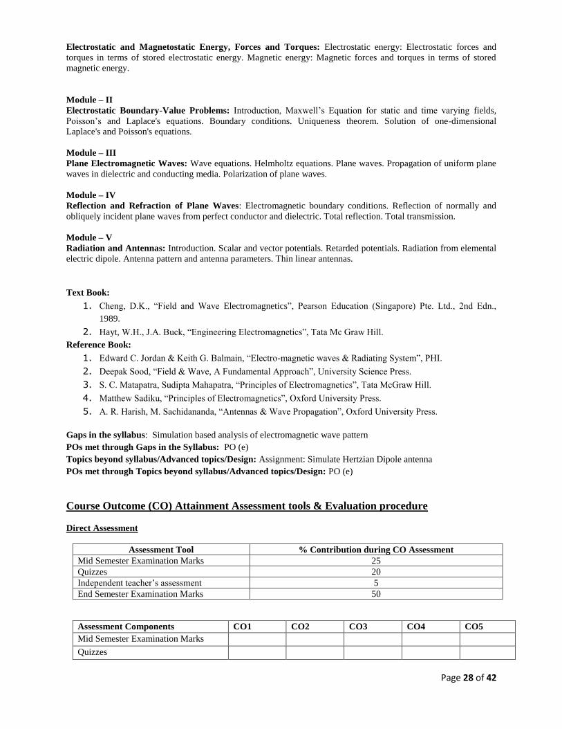
Electrostatic and Magnetostatic Energy, Forces and Torques: Electrostatic energy: Electrostatic forces and
torques in terms of stored electrostatic energy. Magnetic energy: Magnetic forces and torques in terms of stored
magnetic energy.
Module – II
Electrostatic Boundary-Value Problems: Introduction, Maxwell’s Equation for static and time varying fields,
Poisson’s and Laplace's equations. Boundary conditions. Uniqueness theorem. Solution of one-dimensional
Laplace's and Poisson's equations.
Module – III
Plane Electromagnetic Waves: Wave equations. Helmholtz equations. Plane waves. Propagation of uniform plane
waves in dielectric and conducting media. Polarization of plane waves.
Module – IV
Reflection and Refraction of Plane Waves: Electromagnetic boundary conditions. Reflection of normally and
obliquely incident plane waves from perfect conductor and dielectric. Total reflection. Total transmission.
Module – V
Radiation and Antennas: Introduction. Scalar and vector potentials. Retarded potentials. Radiation from elemental
electric dipole. Antenna pattern and antenna parameters. Thin linear antennas.
Text Book:
1. Cheng, D.K., “Field and Wave Electromagnetics”, Pearson Education (Singapore) Pte. Ltd., 2nd Edn.,
1989.
2. Hayt, W.H., J.A. Buck, “Engineering Electromagnetics”, Tata Mc Graw Hill.
Reference Book:
1. Edward C. Jordan & Keith G. Balmain, “Electro-magnetic waves & Radiating System”, PHI.
2. Deepak Sood, “Field & Wave, A Fundamental Approach”, University Science Press.
3. S. C. Matapatra, Sudipta Mahapatra, “Principles of Electromagnetics”, Tata McGraw Hill.
4. Matthew Sadiku, “Principles of Electromagnetics”, Oxford University Press.
5. A. R. Harish, M. Sachidananda, “Antennas & Wave Propagation”, Oxford University Press.
Gaps in the syllabus: Simulation based analysis of electromagnetic wave pattern
POs met through Gaps in the Syllabus: PO (e)
Topics beyond syllabus/Advanced topics/Design: Assignment: Simulate Hertzian Dipole antenna
POs met through Topics beyond syllabus/Advanced topics/Design: PO (e)
Course Outcome (CO) Attainment Assessment tools & Evaluation procedure
Direct Assessment
Assessment Tool % Contribution during CO Assessment
Mid Semester Examination Marks 25
Quizzes 20
Independent teacher’s assessment 5
End Semester Examination Marks 50
Assessment Components CO1 CO2 CO3 CO4 CO5
Mid Semester Examination Marks
Quizzes

Page 29 of 42
End Semester Examination Marks
Independent teacher’s assessment
Indirect Assessment –
1. Student Feedback on Faculty
2. Student Feedback on Course Outcome
1. MAPPING I: (Course Objectives & Outcomes)
Course
Objectives /
Outcomes
1. 2. 3. 4. 5.
A. 3 2 2 2 1
B. 3 3 2 2 2
C. 3 3 2 2 2
D. 3 3 3 2 2
E. 3 3 3 3 3
2. MAPPING II: (CO vs PO)
TABLE NO.1
Course Code and name
EE211
ENGG.
ELECTROMAGNETICS
a
b
c
d
e
f
g
h
i
j
k
l
Course Outcomes/POs
1. 3 3 3 3 3 1 1 1 1 1 1 1
2. 3 3 3 3 3 2 2 1 1 1 1 1
3. 3 3 3 3 3 2 2 2 2 1 1 1
4. 3 3 3 3 3 3 2 2 2 2 2 2
5. 3 3 3 3 3 3 3 3 3 3 2 2
Course Outcome (CO) Attainment Assessment tools & Evaluation procedure
Direct Assessment
Assessment Tool % Contribution during CO Assessment
Mid Sem Examination Marks 25
End Sem Examination Marks 60
Assignment 15
Indirect Assessment
1. Student Feedback on Course Outcome
TABLE NO.2
Course Outcomes Student Feedback Percentage on Course Outcome
CO1

Page 30 of 42
CO2
CO3
CO4
CO5
TABLE NO.3
Assessment Components CO1 CO2 CO3 CO4 CO5
Mid Sem Examination Marks (25%)
Quizzes (20%)
Teacher’s Assessment/ Assignment
Attendance/etc (5%)
End Sem Examination Marks (50%)
TABLE NO.4
Assessment
Components
CO1 CO2 CO3 CO4 CO5
Direct (60%)
Indirect (40%)
Total
3. Mapping between COs and Course Delivery (CD) methods:
Table 4–Submitted in SAR (Self-Assessment
Report) CD Course Delivery methods
CD1 Lecture by use of boards/LCD projectors/OHP
projectors CD2 Tutorials/Assignments
CD3 Seminars
CD4 Mini projects/Projects
CD5 Laboratory experiments/teaching aids
CD6 Industrial/guest lectures
CD7 Industrial visits/in-plant training
CD8 Self- learning such as use of NPTEL materials and
internets CD9 Simulation
Table 5
Course Outcome Course Delivery Method
CO1 CD1, CD8
CO2 CD1, CD8
CO3 CD1, CD8
CO4 CD1, CD2, CD8
CO5 CD1, CD2, CD8
Page 31 of 42
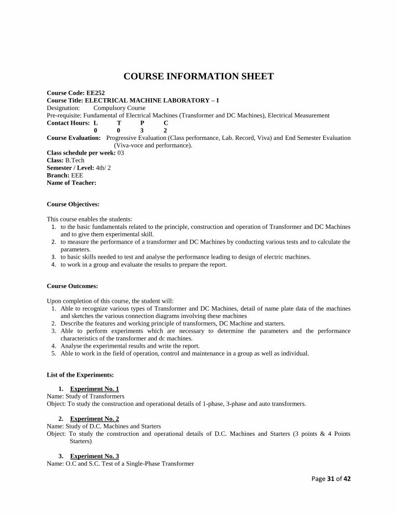
COURSE INFORMATION SHEET
Course Code: EE252
Course Title: ELECTRICAL MACHINE LABORATORY – I
Designation: Compulsory Course
Pre-requisite: Fundamental of Electrical Machines (Transformer and DC Machines), Electrical Measurement
Contact Hours: L T P C
0 0 3 2
Course Evaluation: Progressive Evaluation (Class performance, Lab. Record, Viva) and End Semester Evaluation
(Viva-voce and performance).
Class schedule per week: 03
Class: B.Tech
Semester / Level: 4th/ 2
Branch: EEE
Name of Teacher:
Course Objectives:
This course enables the students:
1. to the basic fundamentals related to the principle, construction and operation of Transformer and DC Machines
and to give them experimental skill.
2. to measure the performance of a transformer and DC Machines by conducting various tests and to calculate the
parameters.
3. to basic skills needed to test and analyse the performance leading to design of electric machines.
4. to work in a group and evaluate the results to prepare the report.
Course Outcomes:
Upon completion of this course, the student will:
1. Able to recognize various types of Transformer and DC Machines, detail of name plate data of the machines
and sketches the various connection diagrams involving these machines
2. Describe the features and working principle of transformers, DC Machine and starters.
3. Able to perform experiments which are necessary to determine the parameters and the performance
characteristics of the transformer and dc machines.
4. Analyse the experimental results and write the report.
5. Able to work in the field of operation, control and maintenance in a group as well as individual.
List of the Experiments:
1. Experiment No. 1
Name: Study of Transformers
Object: To study the construction and operational details of 1-phase, 3-phase and auto transformers.
2. Experiment No. 2
Name: Study of D.C. Machines and Starters
Object: To study the construction and operational details of D.C. Machines and Starters (3 points & 4 Points
Starters)
3. Experiment No. 3
Name: O.C and S.C. Test of a Single-Phase Transformer

Page 32 of 42
Object: a) To find equivalent circuit parameters
b) To find different types of losses and efficiency
c) To draw the OCC and SCC
4. Experiment No. 4
Name: Load test of Single-Phase Transformer
Object: a) To perform load test at unity power factor
b) To calculate the voltage regulation and efficiency
5. Experiment No. 5
Name: Magnetization Characteristic of separately Excited D.C. Generator
Object: To plot Magnetization curve (E Vs. If) for different values of speed
6. Experiment No. 6
Name: Load test of a D.C. Series Generator
Object: a) To Study how the terminal voltage of a DC series generator varies with load current at constant rated
speed
b) To draw the external Characteristics
7. Experiment No. 7
Name: Load test of a D.C. Shunt Generator
Object: Plot the following Characteristics
a) Terminal voltage vs. load current
b) Field current vs. load current
c) Internal or total Characteristics
8. Experiment No. 8
Name: Load test of a D.C. Shunt Motor
Object: Plot the following Characteristics
a) Speed vs. BHP and torque Vs. BHP
b) Current and efficiency vs. BHP
c) Speed vs. torque
9. Experiment No. 9
Name: Speed Control of a D.C. Shunt Motor
Object: Plot the following Characteristics
a) Speed vs. armature voltage (field current being constant)
b) Speed vs. field current (armature voltage being constant)
10. Experiment No. 10
Name: Swinburne’s Test
Object: To conduct Swinburne’s test on D.C. Shunt machine and determine its efficiency while operating as
(i) Motor and (ii) Generator
References:
1. The performance and design of DC machines by A.E. Clayton
2. Theory of AC machines by A. S. Langsdorf,
3. Laboratory experiments on electrical machines by C. K. Chanda & A. Chakraborty, Dhanpat Rai & Co.,
New Delhi
4. Laboratory manual for electromechanics by S. S. Murty, B.P. Singh C. S. Jha and D. P. Kothari, Wiley
Eastern Ltd., Delhi.
Gaps in the syllabus (to meet Industry/Profession requirements): Maintenance and troubleshooting of Electrical
Machine, Special Machines and Drives
POs met through Gaps in the Syllabus:

Page 33 of 42
Topics beyond syllabus/Advanced topics/Design: Electrical Drives
POs met through Topics beyond syllabus/Advanced topics/Design:
Course Outcome (CO) Attainment Assessment tools & Evaluation procedure
Direct Assessment
Assessment Tool % Contribution during CO Assessment
Progressive Evaluation 60
End Semester Evaluation 40
Asseessment Compoents CO1 CO2 CO3 CO4 CO5
Mid Sem Examination Marks √ √ √ √ √
End Sem Examination Marks √ √ √ √ √
Indirect Assessment –
1. Student Feedback
Mapping between Course Objectives and Course Outcomes:
Course
Objectives
Course Outcomes
i ii iii iv v
1 √ √ √ √
2 √ √ √ √
3 √ √ √ √
4 √ √ √
Mapping between CO and PO
Course
Outcomes
Programme Outcomes
a b c d e f g h i j K l
1 3 1 2 2 1 1
2 3 2 1 1 3 1 1
3 3 2 2 3 2
4 2 3 3 1 2 3 2
5 3 1 3 1 2 3 1 1

Page 34 of 42
Course Delivery methods
Lecture by use of boards/LCD projectors
Laboratory experiments/teaching aids
Industrial/guest lectures
Industrial visits/in-plant training
Self- learning such as use of NPTEL materials and internets
Simulation
Mapping Between COs and Course Delivery (CD) methods
Course Outcome Course Delivery Method
CO1 CD1, CD2, CD3, CD4, CD5
CO2 CD1, CD2, CD4, CD5
CO3 CD1, CD2, CD5
CO4 CD1, CD5, CD6
CO5 CD1, CD5, CD6

Page 35 of 42
COURSE INFORMATION SHEET Course code: EE 202
Course title: Electrical Measurement and Instrumentation Lab
Pre-requisite(s): Knowledge of Physics, Electrical Circuits, Measurement and Instrumentation
Credits: L T P
0 0 3
Class schedule per week: 03
Course Objectives:
This course enables the students:
A To state the procedures of measurement of low, medium and high resistances
B To outline the working of display devices like CRO, recorders and plotters. C To explain testing on dc bridge (Wheatstone bridge) for finding fault location and ac bridge,
perform experiment on Energy meter and Range extension of ammeter and voltmeter D To list the different types of transducers and their use in measurement of speed, force,
displacement, temperature and light intensity.
Course Outcomes:
After the completion of this course, students will be able to:
1 Show proper use of measurements on a variety of physical quantities with accuracy. 2 Explain the basic principles of measurement and experimental methods for measuring
mechanical and electrical quantities with the use of transducers 3 Reproduce his acquaintance with the use of AC and DC bridges and display devices. 4 Outline the various methods of measurement of resistances.
5 Design techniques using knowledge of measurement of electric quantities.
Syllabus
LIST OF EXPERIMENTS
Experiment No. 1
Name: Wheatstone bridge
Objective: Measurement of medium range resistance using Wheatstone bridge
Experiment No. 2
Name: Kelvin Double Bridge
Objective: Measurement of low resistance by Kelvin Double Bridge method.
Experiment No. 3
Name: Loss of charge method
Objective: Measurement of high resistance using Loss of charge method.

Page 36 of 42
Experiment No. 4
Name: Localization of cable fault
Objective: Determination of location of point of fault in a cable.
Experiment No. 5
Name: Breakdown voltage of transformer oil
Objective: Measurement of breakdown voltage of transformer oil
Experiment No. 6
Name: Maxwell’s Inductance - Capacitance Bridge
Objective: Measurement of coil constant using Maxwell’s Inductance - Capacitance Bridge.
Experiment No. 7. (a)
Name: Linear Variable Differential Transformer (LVDT)
Objective: Measurement of linear displacement using LVDT.
Experiment No. 7. (b)
Name: Strain Gauge
Objective: Measurement of strain by the use of strain gauge.
Experiment No. 8
Name: Energy meter
Objective: Calibration of single phase Energy meter
Experiment No. 9
Name: Speed Measurement using Stroboscope
Objective: Measurement of speed of a rotating element (DC motor) using stroboscope.
Experiment No. 10
Name: Study Experiment
1. Objective: Study of recorders and plotters like Strip chart recorders, X- Y recorders and
Magnetic tape recorders.
2. Objective: Study of CRO and applications of CRO for measurement of voltage, current,
phase and frequency for sinusoidal, square and triangular waveforms.
3. Objective: Determination of characteristics of optical transducers such as Photovoltaic
cell, Photoconductive cell, Photo transistor cell and Pin photodiode.
4. Objective: Determination of characteristics of thermal transducers such as RTD
(Resistance Temperature Detector), IC Temperature sensor and NTC (Negative
temperature coefficient) Thermistor

Page 37 of 42
Books recommended:
Text book: A Course in Electrical & Electronics Measurement and Instrumentation,
A. K. Sawhney, Dhanpat Rai & Sons
Reference book: Electrical Measurements and Measuring Instruments, Rajendra Prasad,
Khanna Publishers, Delhi – 6.
Electrical Measurement, Golding, Wheeler Publication.
Gaps in the syllabus (to meet Industry/Profession requirements):Extra experiments givenabove can be added
POs met through Gaps in the Syllabus : POs a, b, c, e, f, i, j, l
Topics beyond syllabus/Advanced topics/Design: Process measurement and control.
POs met through Topics beyond syllabus/Advanced topics/Design: POs a, b, c, d, e, f, i, j, k, l
Course Delivery methods
Lecture by use of boards/LCD projectors/OHP projectors
Tutorials/Assignments
Seminars
Mini projects/Projects
Laboratory experiments/teaching aids
Industrial/guest lectures
Industrial visits/in-plant training
Self- learning such as use of NPTEL materials and internets
Simulation
Course Outcome (CO) Attainment Assessment tools & Evaluation procedure
Direct Assessment
Assessment Tool % Contribution during CO Assessment
Progressive Evaluation Marks 60
End Sem Examination Marks 40
Assessment Components CO1 CO2 CO3 CO4 CO5
Progressive Evaluation Marks √ √ √ √ √
End Sem Examination Marks √ √ √ √ √
Indirect Assessment –
1. Student Feedback on Faculty
2. Student Feedback on Course Outcome
Mapping between Objectives and Outcomes

Page 38 of 42
Mapping of Course Outcomes onto Program Outcomes
Course Outcome Program Outcomes
a b c d e f g h i j k l
1 3 3 2 1 2 2 1 3 2 3 2 3 3 3 2 3 2 1 1 2 3 2 3 3 3 3 3 3 2 1 1 3 2 3 4 2 3 3 2 1 2 2 1 3 5 2 3 3 1 3 2 1 2 3 1 3
Mapping Between COs and Course Delivery (CD) methods
CD Course Delivery methods
Course Outcome
Course Delivery Method
CD1 Lecture by use of boards/LCD projectors/OHP projectors CO1 CD5 & CD8
CD2 Tutorials/Assignments CO2 CD4, CD5 & CD8
CD3 Seminars CO3 CD5 & CD8
CD4 Mini projects/Projects CO4 CD4, CD5 & CD8
CD5 Laboratory experiments/teaching aids CO5 CD4, CD5 & CD8
CD6 Industrial/guest lectures CD7 Industrial visits/in-plant training CD8 Self- learning such as use of NPTEL materials and internets CD9 Simulation
Mapping between course objective and course outcome
Course
objective
Course outcomes
i. ii. iii. iv. v.
1. 3 3 1
2. 3 3 2
3. 2 1 3 1
4. 3 3 1 1 3

Page 39 of 42
Open Elective Courses COURSE INFORMATION SHEET
Course code: EE255 Course title: Signals and Systems Pre-requisite(s): Physics, Mathematics and Basics of Electrical Engineering
Co- requisite(s):
Credits: L: 3 T:0 P:0
Class schedule per week: 03
Class: B. Tech
Semester / Level: IV/2
Branch: Minor for other than ECE, IT and CSE
Name of Teacher:
Course Objectives
This course enables the students to:
A. Identify and describe the concepts and properties of signals and systems. B. Learn modeling of systems and apply to correlate the models for different physical systems C. Learn and apply the mathematical tools to analyse the response and stability of systems in
time domain D. Extend and apply the concept for system response and stability analysis in state space
domain
Course Outcomes
After the completion of this course, students will be able to:
1. Identify and describe signals and systems and their properties. 2. Apply mathematical tools such as Laplace Transform, Fourier Transform. 3. Practice response and stability analysis for electrical and mechanical systems 4. Analyse the response and evaluate stability conditions of systems in time domain for
different types of systems 5. Apply the concept state space to solve time domain equations and evaluate stability
conditions.
Syllabus EE255: Signals and Systems
MODULE I:
Objectives and overview:
Signals and systems: Definition, Basis of classification, Representation of common signals and
their detailed properties, System modeling.
Analogous System: Introduction, D Alembert’s Principle, Force – voltage and Force – Current
analogies, Electrical analogue of mechanical, hydraulic and Thermal systems.
Page 40 of 42
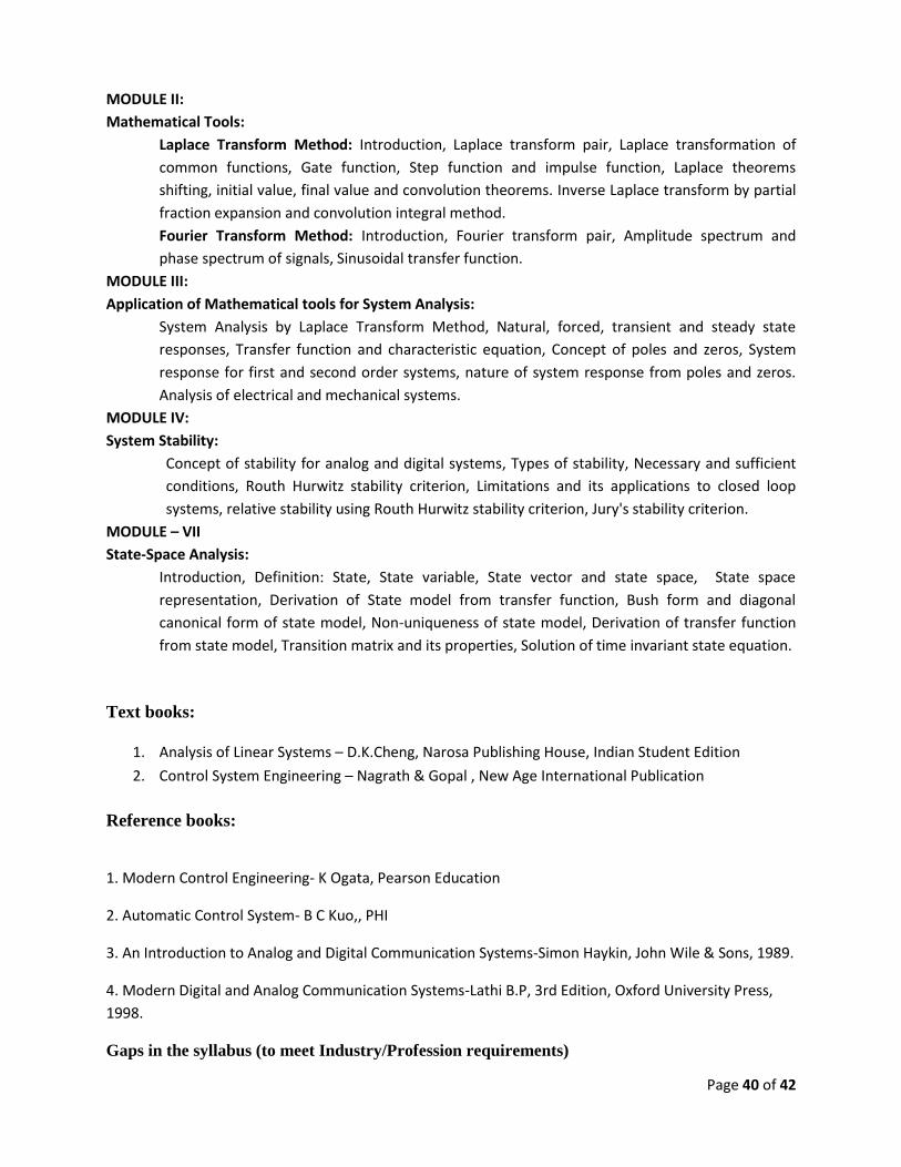
MODULE II:
Mathematical Tools:
Laplace Transform Method: Introduction, Laplace transform pair, Laplace transformation of
common functions, Gate function, Step function and impulse function, Laplace theorems
shifting, initial value, final value and convolution theorems. Inverse Laplace transform by partial
fraction expansion and convolution integral method.
Fourier Transform Method: Introduction, Fourier transform pair, Amplitude spectrum and
phase spectrum of signals, Sinusoidal transfer function.
MODULE III:
Application of Mathematical tools for System Analysis:
System Analysis by Laplace Transform Method, Natural, forced, transient and steady state
responses, Transfer function and characteristic equation, Concept of poles and zeros, System
response for first and second order systems, nature of system response from poles and zeros.
Analysis of electrical and mechanical systems.
MODULE IV:
System Stability:
Concept of stability for analog and digital systems, Types of stability, Necessary and sufficient
conditions, Routh Hurwitz stability criterion, Limitations and its applications to closed loop
systems, relative stability using Routh Hurwitz stability criterion, Jury's stability criterion.
MODULE – VII
State-Space Analysis:
Introduction, Definition: State, State variable, State vector and state space, State space
representation, Derivation of State model from transfer function, Bush form and diagonal
canonical form of state model, Non-uniqueness of state model, Derivation of transfer function
from state model, Transition matrix and its properties, Solution of time invariant state equation.
Text books:
1. Analysis of Linear Systems – D.K.Cheng, Narosa Publishing House, Indian Student Edition
2. Control System Engineering – Nagrath & Gopal , New Age International Publication
Reference books:
1. Modern Control Engineering- K Ogata, Pearson Education
2. Automatic Control System- B C Kuo,, PHI
3. An Introduction to Analog and Digital Communication Systems-Simon Haykin, John Wile & Sons, 1989.
4. Modern Digital and Analog Communication Systems-Lathi B.P, 3rd Edition, Oxford University Press,
1998.
Gaps in the syllabus (to meet Industry/Profession requirements)

Page 41 of 42
POs met through Gaps in the Syllabus
Topics beyond syllabus/Advanced topics/Design
POs met through Topics beyond syllabus/Advanced topics/Design
Course Delivery methods
Lecture by use of boards/LCD projectors/OHP projectors
Tutorials/Assignments
Seminars
Mini projects/Projects
Laboratory experiments/teaching aids
Industrial/guest lectures
Industrial visits/in-plant training
Self- learning such as use of NPTEL materials and internets
Simulation
Course Outcome (CO) Attainment Assessment tools & Evaluation procedure
Direct Assessment
Assessment Tool % Contribution during CO Assessment
QUIZ-I 10
Mid Sem Examination Marks 25
QUIZ-II 10
Assignment 05
End Sem Examination Marks 50
Assessment Compoents CO1 CO2 CO3 CO4
QUIZ-I
Mid Sem Examination Marks
QUIZ-II
Assignment
End Sem Examination Marks
Indirect Assessment –
1. Student Feedback on Faculty
2. Student Feedback on Course Outcome
Mapping between Objectives and Outcomes
Mapping of Course Outcomes onto Program Outcomes
Course Outcome # Program Outcomes
a b c d e f g h i j k l
1 3 2 2 3 1 2 3
Page 42 of 42
2 3 3 3 2 3 3 2 2
3 3 3 3 3 3 2 2 2
4 3 3 3 3 3 3 2 2
5 3 2 3 2 2 2 2
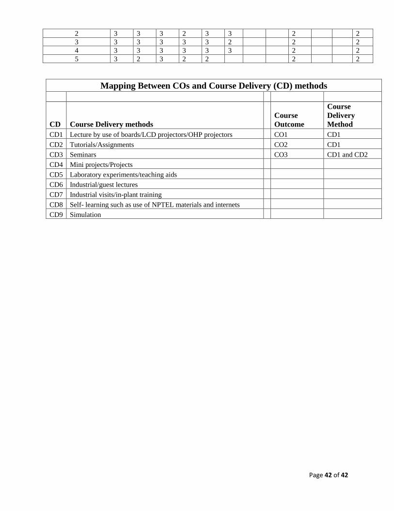
Mapping Between COs and Course Delivery (CD) methods
CD Course Delivery methods
Course
Outcome
Course
Delivery
Method
CD1 Lecture by use of boards/LCD projectors/OHP projectors CO1 CD1
CD2 Tutorials/Assignments CO2 CD1
CD3 Seminars CO3 CD1 and CD2
CD4 Mini projects/Projects
CD5 Laboratory experiments/teaching aids
CD6 Industrial/guest lectures
CD7 Industrial visits/in-plant training
CD8 Self- learning such as use of NPTEL materials and internets
CD9 Simulation