department of eee question bankstudentsfocus.com/notes/anna_university/ece/2sem/ee6201 -...
TRANSCRIPT
DEPARTMENT OF EEE
QUESTION BANK(As Per AUC 2013 REGULATION)
SUB CODE: EE6201
SUB NAME: CIRCUIT THEORY
YEAR : I
SEM : II
www.studentsfocus.com
Unit-I
Basics of Circuits Analysis
PART-A
1. What is meant by linear and nonlinear elements?Linear element shows the linear characteristics of voltage Vs current.
Nonlinear element the current passing through it does not change linearity with the linearchange in applied voltage at a particular frequency.2. What is meant by active and passive elements?
If a circuit element has the capability of enhancing the energy level of a signal passingthrough i t is called an active element.Passive elements do not have any intrinsic means of signal boosting.3. What is meant by unilateral and bilateral elements?
If the magnitude of the current passing through an element is affected due to change in thepolarity of the applied voltage is called unilateral elements.If the current magnitude remains the same even if the applied EMFs polarity is changed iscalled bilateral elements.4. What is a dual network?
In an electrical circuit itself there are pairs of terms, which can be interchanged to get newcircuits. Such pair of dual terms is given below
� Current- Voltage� Open- Short� L-C� R-G� Series – Parallel� Voltage source- Current source� KCL-KVL
5. Define Ohms Law.The potential difference across any two ends of a conductor is directly proportional to the
current flowing between the two ends provided the temperature of the conductor remainsconstant.6. Mention the disadvantages of Ohm’s Law.
• It does not apply to all non metallic conductors• It also does not apply to non linear devices such as zener diode, vacuum tubes etc.• It is true for metal conductors at constant temperature. If the temperature changes the
law is not applicable.7. What is a node, a junction and a branch?
A node of a network is an equipotential surface at which two or more circuit elements arejoined.A junction is that point in a network where three or more circuit elements are joined.A branch is that part of a network which lies between two junction points.
8. What is a super node?
www.studentsfocus.com
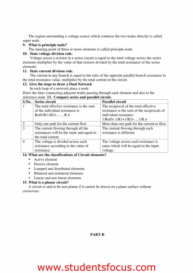
The region surrounding a voltage source which connects the two nodes directly is calledsuper node.9. What is principle node?
The meeting point of three or more elements is called principle node.10. State voltage division rule.
Voltage across a resistor in a series circuit is equal to the total voltage across the serieselements multiplies by the value of that resistor divided by the total resistance of the serieselements.11. State current division rule.
The current in any branch is equal to the ratio of the opposite parallel branch resistance tothe total resistance value, multiplies by the total current in the circuit.12. Give the steps to draw a Dual Network
In each loop of a network place a nodeDraw the lines connecting adjacent nodes passing through each element and also to thereference node. 13. Compare series and parallel circuit.S.No. Series circuit Parallel circuit1 The total effective resistance is the sum
of the individual resistance ieReff=R1+R2+……R n
The reciprocal of the total effectiveresistance is the sum of the reciprocals ofindividual resistance1/Reff= 1/R1+1/R2+….1/R n
2 Only one path for the current flow More than one path for the current to flow3 The current flowing through all the
resistances will be the same and equal tothe total current
The current flowing through eachresistance is different
4 The voltage is divided across eachresistance according to the value ofresistance.
The voltage across each resistance issame which will be equal to the inputvoltage.
14. What are the classifications of Circuit elements?• Active element• Passive element• Lumped and distributed elements• Bilateral and unilateral elements• Linear and non linear elements.
15. What is a planar circuit?A circuit is said to be non planar if it cannot be drawn on a plane surface without
crossovers.
PART-B
www.studentsfocus.com

1.
2.
3. i)Using the node voltage analysis, find all the node voltages and currents in 1/3 ohm and 1/5ohm resistances of figure.
ii) For the mesh-current analysis, explain the rules for constructing mesh impedance matrix andsolving the matrix equation [Z]I = V.
4.
www.studentsfocus.com

5.
www.studentsfocus.com
Unit-II
Network Reduction and Network Theorems for DC and AC Circuits
PART-A
1. Sate superposition theorem.It states that the response of a linear circuit with multiple sources is given by algebraic
sum of response due to individual sources acting alone.2. State Thevenins theorem
It states that any linear bilateral network can be replaced by a single current sourceVTH, in series with single impedance Zth3. State Norton’s theorem
It states that any linear bilateral network can be replaced by a single current source, INin parallel with single impedance Zth.4. State maximum power transfer theorem.
Max power is transferred to load impedance if the load impedance is the complexconjugate of the source impedance.5. State the steps to solve the super position theorem.
� Take only one independent voltage or current source.� Obtain the branch currents.� Repeat the above for other sources.� To determine the net branch current just add the current obtained above.
6. What is the limitation of superposition theorem?� Superposition theorem is valid only for linear systems.� This theorem can be applied for calculating the current through or voltage across in particular element.� But this superposition theorem is not applicable for calculation of the power.
7. State the steps to solve the Thevenin’s Theorem� Remove the load resistance and find the open circuit voltage Voc� Deactivate the consta t sources (fro voltage source remove it by internal resistance & for current
source delete the source by OC) and find the internal resistance (RTH) of the source side looking through the open circuited load terminals
� Obtain the thevenin’s equivalent circuit by connecting VOC in series with RTh� Reconnect the load resistance across the load terminals.
8. List the applications of Thevinins theorem.� It is applied to all linear circuits including electronic circuits represented by the
controlled source.� This theorem is useful when t is desired to know the effect of the response in network
or varying part of the networkIL= VOC / (RTH+RL)
9. State the steps to solve the Norton’s theorem.� Remove the load resistor and find the internal resistance of the source N/W by
deactivating the constant source.� Short the load terminals and find the short circuit current� Norton’s equivalent circuit is drawn by keeping R TH in parallel with ISC
IL= (ISC.RTH) / (RTH+RL)
www.studentsfocus.com

10. What is the maximum power in a circuit?Max power:VO C
2/4 RTH11. Write some applications of maximum power transfer theorem.
� Power amplifiers� Communication system� Microwave transmission
12. What are the limitations of maximum power transfer theorem?� The maximum efficiency can be obtained by using this theorem is only 50% . It is
because of 50% of the power is unnecessarily wasted in Rth.� Therefore this theorem only applicable for communication circuits and not for power
circuits where efficiency is greater importance rather than power delivered.13. Define source transformation.
The current and voltage sources may be inter changed without affecting the remainderof the circuit, this technique is the source transformation. It is the tool for simplifying thecircuit.14. Explain the purpose of star delta transformation.
The transformation of a given set of resistances in star to delta or vice versa provesextremely useful in circuit analysis and the apparent complexity of a given circuit cansometime by very much reduce.
PART-B1.(i) Find the value of R and the current flowing through it in the circuit shown when thecurrent in the branch OA is zero. (8)
ii) Determine the Thevenin’s equivalent for the figure (8)
2. Derive expressions for star connected arms in terms of delta connected arms and deltaconnected arms in terms of star connected arms. (16)
www.studentsfocus.com

3.
4. i) Determine the Thevenin’s equivalent circuit. (8)
(ii) Find the equivalent resistance between B and C in figure (8)
5.
www.studentsfocus.com
www.studentsfocus.com
Unit-III
Resonance and Coupled circuits
PART-A
1. What is meant by Resonance?An A.C circuit is said to be resonance if it behaves as a purely resistive circuit. The
total current drawn by the circuit is then in phase with the applied voltage, and the powerfactor will then unity. Thus at resonance the equivalent complex impedance of the circuit hasno j component.2. Write the expression for the resonant frequency of a RLC series circuit.
Resonant frequency fr=1/2π√LC3. What is resonant frequency?
The frequency at which resonance occurs is called resonant frequency.At resonant frequency XL=XC4. Define series resonance.
A resonance occurs in RLC series circuit called series resonance. Under resonancecondition, the input current is in phase with applied voltage.5. Define Quality factor.
The quality factor is defined as the ratio of maximum energy stored to the energydissipated in one period.6. What are half power frequencies?
In RLC circuits the frequencies at which the power is half the max/min power arecalled half power frequencies.7. Write the characteristics of series resonance.
At resonance impedance in min and equal to resistance therefore current is max.Before resonant frequency the circuit behaves as capacitive circuit and above resonantfrequency the circuit will behave as inductive circuit.
At resonance the magnitude of voltage across the inductance and capacitance will be Qtimes the supply voltage but they are in phase opposition.8. What is anti resonance?
In RLC parallel circuit the current is min at resonance whereas in series resonance thecurrent is max. Therefore the parallel resonance is called anti resonance.9. Write the characteristics of parallel resonance.
At resonance admittance in min and equal to conductance therefore the current is min.Below resonant frequency the circuits behave as inductive circuit and above resonant
frequency the circuit behaves as capacitive circuit.At resonance the magnitude of current through inductance and capacitance will be q
times the current supplied by the source but they are in phase opposition.10. What is Bandwidth and selectivity?
The frequency band within the limits of lower and upper half frequency is calledbandwidth.
BW=f2-f1Selectivity is the ratio of resonant frequency (fr) to the bandwidth.
Selectivity= fr / (f2-f1)
www.studentsfocus.com
11. What are coupled circuits?It refers to circuit involving elements with magnetic coupling. If the flux produced by anelement of a circuit links other elements of the same circuit then the elements are said to bemagnetic coupling.
13. Define self inductance.When permeability is constant the self inductance of a coil is defined as the ratio of
flux linkage and current.14. Define mutual inductance.
When permeability is constant the mutual inductance between two coupled coils isdefined as the ratio of flux linkage in one coil due to common flux and current throughanother coil.15. Define coefficient of coupling.
The amount of coupling between to inductively coupled coils is expressed in terms ofthe coefficient of coupling.
K=M/√L1L2
PART-B1.
2.
www.studentsfocus.com
3.
4.
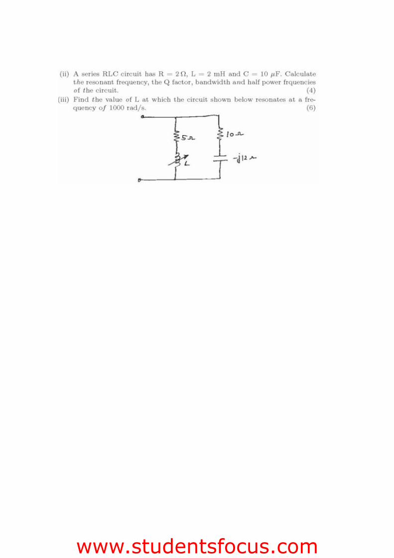
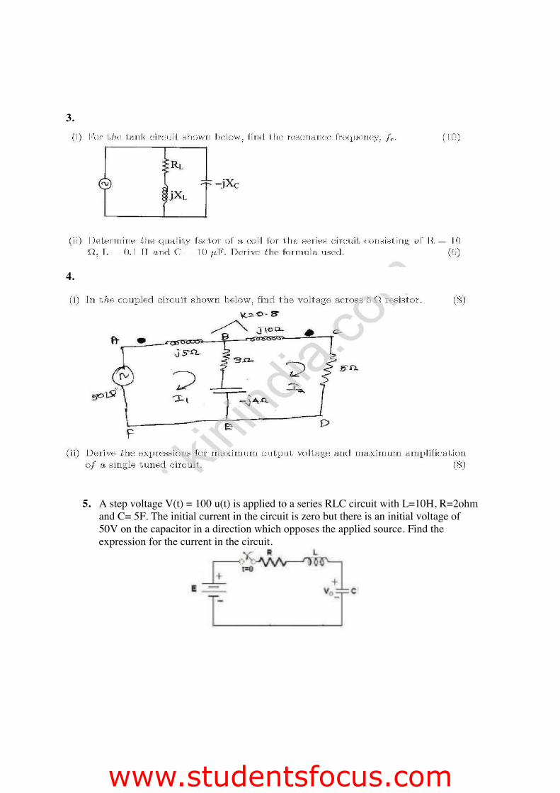
5. A step voltage V(t) = 100 u(t) is applied to a series RLC circuit with L=10H, R=2ohmand C= 5F. The initial current in the circuit is zero but there is an initial voltage of50V on the capacitor in a direction which opposes the applied source. Find theexpression for the current in the circuit.
www.studentsfocus.com
UNIT IV
Transient Response for DC Circuits
PART-A1. What is transient state?
If a network contains energy storage elements, with change in excitation, the currentand voltage change from one state to other state the behavior of the voltage or current when itis changed from one state to another state is called transient state.2. What is transient time?
The time taken for the circuit to change from one steady state to another steady state iscalled transient time.3. What is transient response?
The storage elements deliver their energy to the resistance; hence the response changeswith time, get saturated after sometime, and are referred to the transient response.4. Define time constant of RLC circuit.
The time taken to reach 63.2% of final value in a RL circuit is called the time constantof RL circuit.
Time constant=L/R5. Define time constant of RC circuit.
The time to taken to reach 36.8% of initial current in an RC circuit is called the timeconstant of RC circuit.
Time constant= RC6. What is meant by natural frequency?
If the damping is made zero then the response oscillates with natural frequencywithout any opposition, such a frequency is called natural frequency of oscillations.7. Define damping ratio.
It is the ratio of actual resistance in the circuit to the critical resistance.8.
9.
10.Write down the condition, for the response of RLC series circuit to be under damped andoverdamped for step input.
The response of RLC series circuit with step input in
www.studentsfocus.com

under damped condition: (R/2L)2<(1/LC)Overdamped condition: (R/2L)2>(1/LC)
11. Write down the few applications of RL, RC, RLC circuits.• Coupling circuits• Phase shift circuits• Filters• Resonant circuits• AC bridge circuits• Transformers
12.
13.
14.
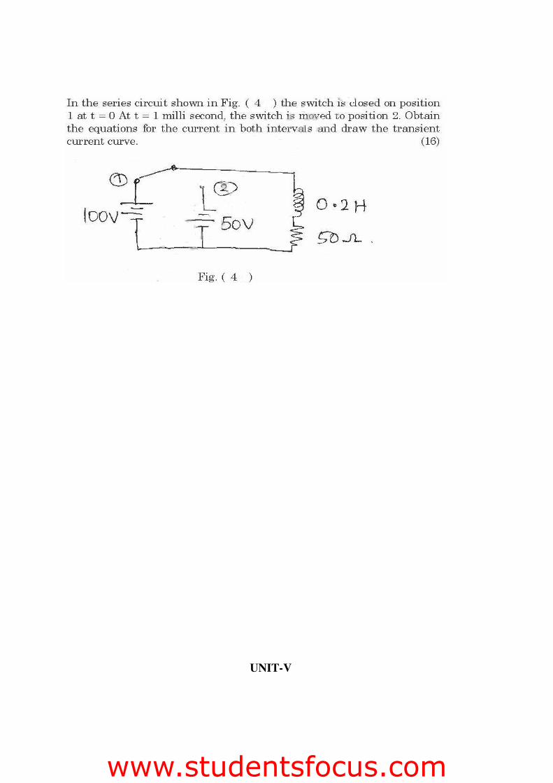
PART-B1.
2.
www.studentsfocus.com

3.
4.
5.
www.studentsfocus.com
UNIT-V
www.studentsfocus.com
ANALYZING THREE PHASE CIRCUITS
PART-A
1. What is phase sequence?Phase sequence of a polyphase system in the order in which different phase quantities reach theirmaximum values.
2.Define line current and phase current.The current flowing through the line is called line currentThe current flowing through the phase is called phase current
2. Define line and phase voltageThe voltage between two lines is called the line voltageThe voltage between any line and the neutral point is called phase voltage.
3. Give the line and phase values in star connectionThe relation between line and phase voltage in star connection is
EL=√3EphThe relation between line current and phase current in a star connection is
IL=Iph4. Give the line and phase values in delta connection
The relation between line voltage and phase voltage in a delta connection isEL=Eph
The relation between line current and phase current in delta connection isIL=√3Iph
5.
6.
7.
8.
9. Write the methods of connections of 3 phase windings?• Independent connection
www.studentsfocus.com
• Star connection and• Delta connection
10. Write few methods available for measuring in 3-phase load.• One wattmeter method• Two wattmeter method• Three wattmeter method
11. List the methods used for power measurement with single wattmeter• Potential lead shift method• T- method• Artificial neutral method• Current transformer method
12. List the methods for unbalanced star connected load• Equivalents delta method• Mesh method• Neutral voltage displacement method
13.
14.
15.
PART-B
1.
2. (i) Three impedances Z1 = 3 45° ohm, Z2 = 10 √2 45° ohm, Z3 = 5 -90° ohm are connectedin series. Calculate applied voltage if voltage across Z1 = 27 -10° V. (8)(ii) A delta connected load as shown in figure is connected across 3 phase 100 volt supply. Determineall line currents. (8)3.
www.studentsfocus.com

4.
5.
www.studentsfocus.com