department of defense standard practiceeveryspec.com/mil-std/mil-std-2000-2999/download... · this...
TRANSCRIPT

AMSC N/A FSG 93GP
INCH-POUND
MIL-STD-2148A(SH)
6 September 2016
SUPERSEDING
MIL-STD-2148(SH)
12 August 1983
DEPARTMENT OF DEFENSE
STANDARD PRACTICE
VIBRATION DAMPING MATERIALS,
PROCEDURES FOR INSTALLATION, MAINTENANCE,
AND REPAIRS
Downloaded from http://www.everyspec.com

MIL-STD-2148A(SH)
ii
FOREWORD
1. This standard is approved for use by the Naval Sea Systems Command, Department of the Navy, and is
available for use by all Departments and Agencies of the Department of Defense.
2. This standard provides instructions for the installation, maintenance, and repair of vibration damping
materials.
3. Damping treatments applied on structures reduce the amplitudes of motion and force at their numerous
resonance frequencies, and thus reduce vibrations.
4. Comments, suggestions, or questions on this document should be addressed to Commander, Naval Sea
Systems Command, ATTN: SEA 05S, 1333 Isaac Hull Avenue, SE, Stop 5160, Washington Navy Yard DC
20376-5160 or emailed to CommandStandards@navy mil, with the subject line “Document Comment”. Since
contact information can change, you may want to verify the currency of this address information using the ASSIST
Online database at https://assist.dla.mil.
Downloaded from http://www.everyspec.com

MIL-STD-2148A(SH)
iii
CONTENTS
PARAGRAPH PAGE
1. SCOPE ...................................................................................................................................................................... 1 1.1 Scope. ................................................................................................................................................................. 1 1.2 Classification. ..................................................................................................................................................... 1
2. APPLICABLE DOCUMENTS ................................................................................................................................ 2 2.1 General. .............................................................................................................................................................. 2 2.2 Government documents. ..................................................................................................................................... 2
2.2.1 Specifications, standards, and handbooks. ................................................................................................... 2 2.2.2 Other Government documents, drawings, and publications. ....................................................................... 3
2.3 Non-Government publications. ........................................................................................................................... 4 2.4 Order of precedence. ........................................................................................................................................... 5
3. DEFINITIONS ......................................................................................................................................................... 5 3.1 Abrasive blasting. ............................................................................................................................................... 5 3.2 Anode. ................................................................................................................................................................ 5 3.3 Anti-corrosion paint. ........................................................................................................................................... 5 3.4 Antifouling paint. ................................................................................................................................................ 5 3.5 Brush blasting. .................................................................................................................................................... 5 3.6 Damping. ............................................................................................................................................................ 5 3.7 Damping material. .............................................................................................................................................. 5 3.8 Dry film thickness. ............................................................................................................................................. 6 3.9 Epoxy. ................................................................................................................................................................. 6 3.10 Free-layer damping. .......................................................................................................................................... 6 3.11 Galvanic corrosion. ........................................................................................................................................... 6 3.12 Near-white metal. ............................................................................................................................................. 6 3.13 Resonance frequency. ....................................................................................................................................... 6 3.14 Restraining layer. .............................................................................................................................................. 6 3.15 Solvent. ............................................................................................................................................................. 6 3.16 Sweep-blasting. ................................................................................................................................................. 6 3.17 Template. .......................................................................................................................................................... 6 3.18 Very high bond (VHB) tape.............................................................................................................................. 6
4. GENERAL REQUIREMENTS ................................................................................................................................ 6 4.1 Discussion. .......................................................................................................................................................... 6 4.2 General. .............................................................................................................................................................. 7
4.2.1 Interference from other systems. ................................................................................................................. 7 4.2.2 Pre-forming damping materials. .................................................................................................................. 7 4.2.3 Areas with reinforced members. .................................................................................................................. 7
4.2.3.1 Areas with irregularly shaped members. .............................................................................................. 7 4.2.3.2 Standard size tiles. ................................................................................................................................ 7
4.2.4 Damage preventive measures. ..................................................................................................................... 7 4.2.4.1 Welding or burning near type VI damping tiles. .................................................................................. 7
4.2.5 Constraining layers. ..................................................................................................................................... 7 4.2.5.1 Studs, nuts, and washers. ...................................................................................................................... 9
4.2.6 Materials installed in combination with damping treatments. ..................................................................... 9 4.2.6.1 Acoustic absorptive or thermal insulation. ........................................................................................... 9 4.2.6.2 Reflector and decoupler tiles. ............................................................................................................. 10 4.2.6.3 Acoustic absorber tiles. ....................................................................................................................... 10 4.2.6.4 Cableway hangers. .............................................................................................................................. 10 4.2.6.5 Air pollution regulations. .................................................................................................................... 10
4.3 Submarines. ...................................................................................................................................................... 10 4.3.1 Main ballast tanks. ..................................................................................................................................... 10 4.3.2 Tanks: bilge-collecting, main lubricating oil and lubricating oil settling, shaft lubricating oil sump,
surge, depth control, sanitary, and potable water. ..................................................................................... 10 4.3.3 Superstructure, fairwater, and other free-flooded spaces. .......................................................................... 11 4.3.4 Hull frames. ............................................................................................................................................... 11
Downloaded from http://www.everyspec.com
MIL-STD-2148A(SH)
iv
PARAGRAPH PAGE
4.3.5 Machinery or noise-critical equipment foundations, bulkheads, and girders. ............................................ 11 4.3.6 Platform decks and supporting beams. ...................................................................................................... 11 4.3.7 Sonar domes. ............................................................................................................................................. 11
4.4 Surface ships. .................................................................................................................................................... 11 4.4.1 Hull, frames, longitudinal stiffeners, and keel. .......................................................................................... 11 4.4.2 Bulkheads and platform decks. .................................................................................................................. 11 4.4.3 Surface ship machinery foundations. ......................................................................................................... 12 4.4.4 Fuel oil and salt water tanks. ..................................................................................................................... 12 4.4.5 Sonar domes. ............................................................................................................................................. 12
4.5 General health and safety requirements. ........................................................................................................... 12 4.5.1 General health hazards. .............................................................................................................................. 12
4.5.1.1 Paint materials. ................................................................................................................................... 12 4.5.1.2 Adhesive materials.............................................................................................................................. 12 4.5.1.3 Damping materials. ............................................................................................................................. 13 4.5.1.4 Surface preparation materials. ............................................................................................................ 13
4.5.2 General safety measures. ........................................................................................................................... 13 4.5.2.1 Working environment. ........................................................................................................................ 13 4.5.2.2 Respiratory protection. ....................................................................................................................... 14
4.5.2.2.1 Types of respirators. .................................................................................................................... 14 4.5.2.3 Eye protection. .................................................................................................................................... 14
4.5.2.3.1 Eyewashes. .................................................................................................................................. 14 4.5.2.4 Protective clothing. ............................................................................................................................. 14 4.5.2.5 Safety precautions for abrasive blasting. ............................................................................................ 14
4.5.2.5.1 Preventive measures. ................................................................................................................... 14 4.5.2.5.2 Requirements prior to blasting operations. .................................................................................. 14 4.5.2.5.3 Pre-abrasive blasting inspection. ................................................................................................. 15 4.5.2.5.4 Post abrasive blasting inspection. ................................................................................................ 15 4.5.2.5.5 Abrasive blasting protective equipment. ...................................................................................... 15 4.5.2.5.6 Staging. ........................................................................................................................................ 15
4.5.2.6 Safety precautions for mixing paint. ................................................................................................... 15 4.5.2.6.1 Fire prevention precautions. ........................................................................................................ 15 4.5.2.6.2 Accidental ignition. ...................................................................................................................... 15 4.5.2.6.3 Electrical equipment. ................................................................................................................... 15 4.5.2.6.4 Personnel protective precautions. ................................................................................................ 15 4.5.2.6.5 Sensitivity, allergic reactions, and pulmonary disorders.............................................................. 15 4.5.2.6.6 Vinyl paints. ................................................................................................................................. 16 4.5.2.6.7 Epoxy paints. ............................................................................................................................... 16
4.5.2.6.7.1 Dermatitis and allergy hazard. .............................................................................................. 16 4.5.2.6.7.2 Epoxy solvents. ..................................................................................................................... 16
4.5.2.7 Safety precautions for paint application. ............................................................................................ 16 4.5.2.7.1 Danger area. ................................................................................................................................. 16 4.5.2.7.2 Application by brush or roller. ..................................................................................................... 16 4.5.2.7.3 Vinyl and epoxy paints. ............................................................................................................... 16 4.5.2.7.4 Application by spray. ................................................................................................................... 16 4.5.2.7.5 Fire prevention precautions. ........................................................................................................ 17 4.5.2.7.6 Application in confined spaces. ................................................................................................... 17 4.5.2.7.7 Explosion-proof lamps. ................................................................................................................ 17 4.5.2.7.8 Gas-free testing. ........................................................................................................................... 17 4.5.2.7.9 Ventilation. .................................................................................................................................. 17 4.5.2.7.10 Personnel protective precautions. .............................................................................................. 17 4.5.2.7.11 Protective clothing. .................................................................................................................... 17 4.5.2.7.12 Showers. .................................................................................................................................... 17 4.5.2.7.13 Cleaning spray guns. .................................................................................................................. 17 4.5.2.7.14 Epoxy paints. ............................................................................................................................. 17
Downloaded from http://www.everyspec.com

MIL-STD-2148A(SH)
v
PARAGRAPH PAGE
4.5.2.8 Safety precautions for adhesive mixing and application. .................................................................... 18 4.5.2.9 Cleaning with degreasing solvents...................................................................................................... 18
4.5.2.9.1 Eye protection. ............................................................................................................................. 18 4.5.2.9.2 Skin protection. ............................................................................................................................ 18
5. DETAILED REQUIREMENTS ............................................................................................................................. 18 5.1 General. ............................................................................................................................................................ 18 5.2 Common requirements...................................................................................................................................... 19
5.2.1 Surface preparation – dry spaces. .............................................................................................................. 19 5.2.1.1 Cleaning steel surfaces in dry spaces. ................................................................................................. 19
5.2.2 Surface preparation – wet spaces. .............................................................................................................. 20 5.2.2.1 Cleaning of steel surfaces in wet spaces. ............................................................................................ 20
5.2.3 Surface preparation – gear cases. ............................................................................................................... 20 5.2.3.1 Gear cases and structures that operate at temperatures of 80 to 155 °F .............................................. 20
5.2.4 Surface preparation – non-steel surfaces. .................................................................................................. 20 5.2.4.1 Non-steel surface cleaning. ................................................................................................................. 20 5.2.4.2 GRP surface cleaning. ........................................................................................................................ 20
5.2.5 Surface preparation – surface ship tanks. .................................................................................................. 21 5.2.5.1 Cleaning of surface ship tanks. ........................................................................................................... 21
5.2.6 Studs, nuts, and washers. ........................................................................................................................... 21 5.2.6.1 Attachment of studs. ........................................................................................................................... 21 5.2.6.2 Protection of stud threads. .................................................................................................................. 21 5.2.6.3 Anti-seize compound. ......................................................................................................................... 21
5.2.6.3.1 Studs and related materials. ......................................................................................................... 21 5.2.7 Protective coatings. .................................................................................................................................... 22
5.2.7.1 Environmental requirements for coatings. .......................................................................................... 23 5.2.7.2 Epoxy coatings. .................................................................................................................................. 23
5.2.7.2.1 Dry spaces. ................................................................................................................................... 23 5.2.7.2.2 Wet spaces. .................................................................................................................................. 23 5.2.7.2.3 Drying time. ................................................................................................................................. 23
5.2.7.3 Powder coating. .................................................................................................................................. 24 5.2.7.3.1 Dry spaces. ................................................................................................................................... 24 5.2.7.3.2 Wet spaces. .................................................................................................................................. 24
5.2.7.4 Ultra high solids coatings. .................................................................................................................. 24 5.2.7.4.1 Dry spaces. ................................................................................................................................... 25 5.2.7.4.2 Wet spaces. .................................................................................................................................. 26
5.2.7.5 Application of coatings. ...................................................................................................................... 26 5.2.7.5.1 Dry spaces. ................................................................................................................................... 26 5.2.7.5.2 Wet spaces. .................................................................................................................................. 27 5.2.7.5.3 Gear cases and structures that operate at temperatures of 80 to 155 °F. ...................................... 27 5.2.7.5.4 Non-steel surfaces. ....................................................................................................................... 27
5.2.8 Amine bloom. ............................................................................................................................................ 27 5.2.8.1 Examination for amine bloom. ........................................................................................................... 27 5.2.8.2 Amine bloom examination and removal procedure. ........................................................................... 27 5.2.8.3 Referee test procedure for detection of amine bloom. ........................................................................ 28
5.2.9 Adhesive. ................................................................................................................................................... 28 5.2.9.1 Environmental requirements. .............................................................................................................. 28 5.2.9.2 Preparation of MIL-A-24456 epoxy adhesive. ................................................................................... 29
5.2.9.2.1 Cleaning. ...................................................................................................................................... 29 5.2.9.3 3M™ VHB™ tape, or equal as approved by NAVSEA. .................................................................... 29
5.2.9.3.1 Adhesive tape application to free-layer or restrained layer tiles. ................................................. 29 5.2.9.3.2 Adhesive taped free-layer or restrained layer tile application to structure. .................................. 30 5.2.9.3.3 Adhesive tape application to constrained layer tiles. ................................................................... 30 5.2.9.3.4 Adhesive taped constrained layer tile application to structure. .................................................... 32
5.2.10 Corrosion protection, habitability, and antifouling paint application. ..................................................... 33
Downloaded from http://www.everyspec.com

MIL-STD-2148A(SH)
vi
PARAGRAPH PAGE
5.2.10.1 Corrosion protection and habitability area paints. ............................................................................ 33 5.2.10.2 Heavy plate damping. ....................................................................................................................... 33 5.2.10.3 Type III damping systems on surface ships. ..................................................................................... 33 5.2.10.4 Antifouling paints. ............................................................................................................................ 34
5.2.11 Fitting around weld beads. ....................................................................................................................... 34 5.3 Installation details for types II, III, V, and VI damping tiles. ........................................................................... 34
5.3.1 Installation of type II (MIL-PRF-23653, class 1, class 2, class 2.5, and class 3) damping tiles on
lightweight plate ⅛- to 11⁄16-inch thick and greater, but less than ¾-inch thick. ......................................... 34
5.3.2 Materials. ................................................................................................................................................... 34 5.3.2.1 Damping tiles. ..................................................................................................................................... 34 5.3.2.2 Adhesive. ............................................................................................................................................ 34 5.3.2.3 Restraining materials. ......................................................................................................................... 35 5.3.2.4 Protective materials. ........................................................................................................................... 35 5.3.2.5 Cleaning materials. ............................................................................................................................. 35
5.3.3 Safety precautions and environmental control. .......................................................................................... 35 5.3.3.1 Handling damping tiles. ...................................................................................................................... 35 5.3.3.2 Protective measures used when handling damping materials. ............................................................ 35 5.3.3.3 Hazardous materials and waste. .......................................................................................................... 35
5.3.4 Surface preparation prior to installation of damping tiles. ......................................................................... 35 5.3.4.1 Ballast and trim tank interiors. ............................................................................................................ 35
5.3.4.1.1 Attachment of studs. .................................................................................................................... 35 5.3.5 Fitting of tiles. ............................................................................................................................................ 35
5.3.5.1 Areas requiring a restraining layer or restraining nuts. ....................................................................... 35 5.3.5.2 Areas not requiring a restraining layer or restraining studs (free-layer damping). ............................. 35 5.3.5.3 Fitting around weld beads. .................................................................................................................. 35 5.3.5.4 Drilling and punching holes, type II tiles. ........................................................................................... 36 5.3.5.5 Preforming. ......................................................................................................................................... 36
5.3.6 Preparation of the adhesive. ....................................................................................................................... 36 5.3.7 Installation of damping materials. ............................................................................................................. 36
5.3.7.1 Ballast, trim tank interiors, and all other spaces that require a restraining layer system. ................... 36 5.3.7.1.1 Installation of the restraining layer and restraining nuts. ............................................................. 37
5.3.7.2 Installation of free-layer type II, class 1, 2, 2.5, and 3 tiles in areas not requiring restraining
layer/restraining studs. ....................................................................................................................... 37 5.3.8 Paint application. ....................................................................................................................................... 37
5.4 Requirements for installation of type II damping tiles on heavy steel plate, ¾ inch or greater. ....................... 37 5.4.1 Materials. ................................................................................................................................................... 38
5.4.1.1 Damping tiles. ..................................................................................................................................... 38 5.4.1.2 Adhesive. ............................................................................................................................................ 38 5.4.1.3 Constraining materials. ....................................................................................................................... 38 5.4.1.4 Protective materials. ........................................................................................................................... 38 5.4.1.5 Cleaning materials. ............................................................................................................................. 38
5.4.2 Safety precautions and environmental control. .......................................................................................... 38 5.4.2.1 Handling damping tiles. ...................................................................................................................... 39 5.4.2.2 Protective measures used when handling damping materials. ............................................................ 39 5.4.2.3 Hazardous materials and waste. .......................................................................................................... 39
5.4.3 Surface preparation prior to installation of damping tiles. ......................................................................... 39 5.4.3.1 Attachment of studs. ........................................................................................................................... 39
5.4.3.1.1 Protection of stud threads. ........................................................................................................... 39 5.4.4 Fitting of tiles. ............................................................................................................................................ 39
5.4.4.1 Selecting and fitting of the constraining layer. ................................................................................... 39 5.4.4.2 Painting. .............................................................................................................................................. 39 5.4.4.3 Tile fitting around weld beads. ........................................................................................................... 39 5.4.4.4 Drilling and punching holes. ............................................................................................................... 39 5.4.4.5 Cutting. ............................................................................................................................................... 39
Downloaded from http://www.everyspec.com

MIL-STD-2148A(SH)
vii
PARAGRAPH PAGE
5.4.5 Preparation of the adhesive. ....................................................................................................................... 39 5.4.6 Installation of damping materials. ............................................................................................................. 40
5.4.6.1 Damping tiles. ..................................................................................................................................... 40 5.4.6.2 Constraining layer. .............................................................................................................................. 40
5.4.6.2.1 Alternate steel constraining layer application for shop use only. ................................................ 40 5.4.6.3 Attachment of nuts and washers. ........................................................................................................ 40
5.4.7 Paint application. ....................................................................................................................................... 40 5.5 Requirements for installation of type III damping tiles. ................................................................................... 41
5.5.1 Materials. ................................................................................................................................................... 41 5.5.1.1 Damping tiles. ..................................................................................................................................... 41 5.5.1.2 Adhesive. ............................................................................................................................................ 41 5.5.1.3 Protective materials. ........................................................................................................................... 41 5.5.1.4 Cleaning materials. ............................................................................................................................. 41
5.5.2 Safety precautions and environmental control. .......................................................................................... 41 5.5.2.1 Handling damping tile. ....................................................................................................................... 41 5.5.2.2 Handling of bonding materials. .......................................................................................................... 41
5.5.3 Surface preparation prior to installation of tiles. ........................................................................................ 41 5.5.4 Preparation of tiles. .................................................................................................................................... 41
5.5.4.1 Tile cutting. ......................................................................................................................................... 41 5.5.5 Preparation of adhesive. ............................................................................................................................. 41 5.5.6 Tile installation. ......................................................................................................................................... 41
5.5.6.1 Fitting of tiles. ..................................................................................................................................... 41 5.5.6.2 Preforming. ......................................................................................................................................... 41 5.5.6.3 Precautions.......................................................................................................................................... 42 5.5.6.4 Bonding. ............................................................................................................................................. 42
5.5.7 Paint application. ....................................................................................................................................... 42 5.6 Requirements for the installation of type V, (MIRL no. 3) class 1 damping tiles on steel plate ½ inch or less
in flooded and non-flooded areas. .................................................................................................................... 42 5.6.1 Materials. ................................................................................................................................................... 42
5.6.1.1 Damping tiles. ..................................................................................................................................... 42 5.6.1.2 Adhesive. ............................................................................................................................................ 42 5.6.1.3 Restraining materials. ......................................................................................................................... 42 5.6.1.4 Protective materials. ........................................................................................................................... 42 5.6.1.5 Cleaning materials. ............................................................................................................................. 42
5.6.2 Safety precautions and environmental control. .......................................................................................... 42 5.6.2.1 Handling of damping tiles. ................................................................................................................. 42 5.6.2.2 Handling of bonding materials. .......................................................................................................... 42
5.6.3 Surface preparation prior to installation of type V, class 1 damping tiles. ................................................ 43 5.6.3.1 Installation of studs. ............................................................................................................................ 43
5.6.4 Fitting of tiles. ............................................................................................................................................ 43 5.6.4.1 Areas requiring a restraining layer or nuts. ......................................................................................... 43 5.6.4.2 Areas not requiring a restraining layer................................................................................................ 43 5.6.4.3 Tile fitting around weld beads. ........................................................................................................... 43 5.6.4.4 Drilling and punching holes. ............................................................................................................... 43 5.6.4.5 Cutting. ............................................................................................................................................... 43
5.6.5 Preparation of the adhesive. ....................................................................................................................... 43 5.6.6 Installation of damping materials. ............................................................................................................. 43
5.6.6.1 Damping tiles. ..................................................................................................................................... 43 5.6.6.2 Restraining layer and restraining nuts. ................................................................................................ 44 5.6.6.3 Installation of tiles in areas not requiring a restraining layer. ............................................................. 44
5.6.6.3.1 Preventing the tiles from slipping. ............................................................................................... 44 5.6.7 Paint application. ....................................................................................................................................... 44
5.7 Requirements for the installation of type V, (MIRL no. 3) class 2 damping tiles on 9⁄16- to ¾-inch steel plate in
non-flooded areas. ............................................................................................................................................ 44
Downloaded from http://www.everyspec.com

MIL-STD-2148A(SH)
viii
PARAGRAPH PAGE
5.7.1 Materials. ................................................................................................................................................... 44 5.7.1.1 Damping tiles. ..................................................................................................................................... 44 5.7.1.2 Adhesive. ............................................................................................................................................ 44 5.7.1.3 Constraining materials. ....................................................................................................................... 45 5.7.1.4 Protective materials. ........................................................................................................................... 45 5.7.1.5 Cleaning materials. ............................................................................................................................. 45
5.7.2 Safety precautions and environmental control. .......................................................................................... 45 5.7.2.1 Handling of bonding materials. .......................................................................................................... 45
5.7.3 Surface preparation prior to installation of type V, class 2 tiles. ............................................................... 45 5.7.3.1 Attachment of studs. ........................................................................................................................... 45 5.7.3.2 Cleaning and painting the steel surfaces. ............................................................................................ 45
5.7.4 Fitting the type V, class 2 tiles and the constraining layer......................................................................... 45 5.7.4.1 Drilling and punching holes. ............................................................................................................... 45 5.7.4.2 Cutting. ............................................................................................................................................... 45
5.7.5 Preparation of the adhesive. ....................................................................................................................... 45 5.7.6 Installation of type V, class 2 damping materials. ..................................................................................... 45
5.7.6.1 Bonding the tiles to the constraining layer. ........................................................................................ 45 5.7.6.1.1 Alternate aluminum constraining layer application for shop use only. ........................................ 46
5.7.6.2 Bonding the tiles and constraining layer to the steel plating............................................................... 46 5.7.6.2.1 Providing a smooth surface. ......................................................................................................... 46
5.7.7 Paint application. ....................................................................................................................................... 46 5.8 Installation of type VI, class 1 damping tiles on lightweight plate ⅛- to
11⁄16-inch thick and greater, but less than
¾-inch thick. .................................................................................................................................................... 46 5.8.1 Materials. ................................................................................................................................................... 46
5.8.1.1 Damping tiles. ..................................................................................................................................... 46 5.8.1.2 Adhesive. ............................................................................................................................................ 46 5.8.1.3 Restraining materials for areas requiring a restraining layer or restraining washer nuts. ................... 46 5.8.1.4 Protective materials. ........................................................................................................................... 46 5.8.1.5 Cleaning materials. ............................................................................................................................. 46
5.8.2 Safety precautions and environmental control. .......................................................................................... 47 5.8.2.1 Handling damping tiles. ...................................................................................................................... 47 5.8.2.2 Protective measures used when handling damping materials. ............................................................ 47 5.8.2.3 Hazardous materials and waste. .......................................................................................................... 47
5.8.3 Surface preparation prior to installation of damping tiles. ......................................................................... 47 5.8.3.1 Ballast and trim tank interiors. ............................................................................................................ 47
5.8.3.1.1 Attachment of studs. .................................................................................................................... 47 5.8.3.1.2 Protection of stud threads. ........................................................................................................... 47
5.8.4 Fitting of tiles. ............................................................................................................................................ 47 5.8.4.1 Areas requiring restraining studs. ....................................................................................................... 47 5.8.4.2 Areas not requiring restraining studs. ................................................................................................. 47 5.8.4.3 Fitting around weld beads. .................................................................................................................. 47 5.8.4.4 Cutting of tiles and holes, type VI tiles. .............................................................................................. 47
5.8.4.4.1 Sealing edges of type VI cut tiles. ............................................................................................... 47 5.8.4.5 Welding or burning near type VI damping tiles. ................................................................................ 47
5.8.5 Preparation of the adhesive. ....................................................................................................................... 47 5.8.6 Installation of damping materials. ............................................................................................................. 48
5.8.6.1 Ballast and trim tank interiors. ............................................................................................................ 48 5.8.6.1.1 Installation of the restraining washers and locknuts, and CRES washer nuts. ............................. 48
5.8.6.2 Installation of type VI, class 1 tiles in areas not requiring restraining studs. ..................................... 48 5.8.7 Paint application. ....................................................................................................................................... 48
5.9 Repair and maintenance. ................................................................................................................................... 48 5.9.1 Damage preventive measures. ................................................................................................................... 49 5.9.2 Minor damage. ........................................................................................................................................... 49 5.9.3 Major damage. ........................................................................................................................................... 49
Downloaded from http://www.everyspec.com
MIL-STD-2148A(SH)
ix
PARAGRAPH PAGE
5.9.4 Replacement of studs. ................................................................................................................................ 49 5.9.5 Inspection of structure. .............................................................................................................................. 49 5.9.6 Free-layer damping (type II, all classes). ................................................................................................... 50
5.9.6.1 Repair of minor damage to damping treatments. ................................................................................ 50 5.9.6.2 Repair of major damage to damping treatments. ................................................................................ 50 5.9.6.3 Repainting. .......................................................................................................................................... 50
5.9.7 Free-layer damping (type III). ................................................................................................................... 50 5.9.7.1 Cleaning of hull plate and bulkhead tiles. ........................................................................................... 50 5.9.7.2 Cleaning of tiles inside fuel tanks. ...................................................................................................... 50 5.9.7.3 Repair of damping treatment. ............................................................................................................. 50 5.9.7.4 Minor damage. .................................................................................................................................... 50 5.9.7.5 Major damage. .................................................................................................................................... 51
5.9.8 Free-layer damping (type V, class 1). ........................................................................................................ 51 5.9.8.1 Cleaning of tiles. ................................................................................................................................. 51 5.9.8.2 Repair of minor damage to damping treatments. ................................................................................ 51 5.9.8.3 Repair of major damage to damping treatments. ................................................................................ 51
5.9.9 Restrained damping (type II, all classes). .................................................................................................. 51 5.9.9.1 Cleaning of tiles and restraining layers. .............................................................................................. 51 5.9.9.2 Repair of minor damage to damping treatments. ................................................................................ 52 5.9.9.3 Repair of major damage to damping treatments. ................................................................................ 52 5.9.9.4 Replacing missing studs. .................................................................................................................... 52 5.9.9.5 Repainting. .......................................................................................................................................... 52
5.9.10 Restrained damping (type V, class 1). ..................................................................................................... 53 5.9.10.1 Cleaning of tiles and restraining layers. ............................................................................................ 53 5.9.10.2 Repair of minor damage to damping treatments. .............................................................................. 53 5.9.10.3 Repair of major damage to damping treatments. .............................................................................. 53 5.9.10.4 Replacing missing studs. .................................................................................................................. 53 5.9.10.5 Repainting. ........................................................................................................................................ 53
5.9.11 Constrained damping (type II, all classes). .............................................................................................. 54 5.9.11.1 Cleaning of damping treatment. ........................................................................................................ 54 5.9.11.2 Minor repair of damping treatment. .................................................................................................. 54 5.9.11.3 Major repair of damping treatment. .................................................................................................. 54 5.9.11.4 Replacement of studs. ....................................................................................................................... 54 5.9.11.5 Constraining layer removal. .............................................................................................................. 54
5.9.12 Constrained damping (type V, class 2). ................................................................................................... 54 5.9.12.1 Cleaning of damping treatment. ........................................................................................................ 54 5.9.12.2 Minor repair of damping treatment. .................................................................................................. 55 5.9.12.3 Major repair of damping treatment. .................................................................................................. 55 5.9.12.4 Repainting. ........................................................................................................................................ 55
5.9.13 Constrained damping (type VI). .............................................................................................................. 55 5.9.13.1 Cleaning of tiles and constraining layers. ......................................................................................... 55 5.9.13.2 Repair of minor damage to damping treatments. .............................................................................. 55 5.9.13.3 Repair of major damage to damping treatments. .............................................................................. 56 5.9.13.4 Repainting. ........................................................................................................................................ 56
5.10 Validation of proper installation. .................................................................................................................... 56 5.10.1 General. ................................................................................................................................................... 56 5.10.2 Installation inspection. ............................................................................................................................. 56
5.10.2.1 Stud welding. .................................................................................................................................... 56 5.10.2.2 Tile location. ..................................................................................................................................... 56
5.10.3 Post sea-trial inspections. ......................................................................................................................... 56 6. NOTES ................................................................................................................................................................... 56
6.1 Intended use. ..................................................................................................................................................... 56 6.2 Acquisition requirements. ................................................................................................................................. 57 6.3 Type I damping material. .................................................................................................................................. 57
Downloaded from http://www.everyspec.com
MIL-STD-2148A(SH)
x
PARAGRAPH PAGE
6.4 Type IV damping material. ............................................................................................................................... 57 6.5 Health and safety. ............................................................................................................................................. 57 6.6 Subject term (key word) listing. ....................................................................................................................... 57 6.7 Changes from previous issue. ........................................................................................................................... 57
LIST OF FIGURES
FIGURE PAGE
1. CRES 316 washer nut assembly. ............................................................................................................................ 58
2. Typical installation of damping tiles on hull frames (not to scale). ........................................................................ 59
3. Cross-section view of typical installation of constrained MIL-PRF-23653 tiles at tank top and side where
plate is subject to submergence pressure and space is required for attachments (not to scale). ............................. 60
4. Cross-section view of typical installation of unconstrained MIL-PRF-23653 tiles at tank top and side where
plate is not subject to submergence pressure and space is required for attachments (not to scale). ....................... 60
5. Details of typical installations of constrained and free-layered damping tiles at end of acoustic absorptive or
thermal insulation (not to scale). ............................................................................................................................ 61
6. Cross-section of typical installation of restrained MIL-PRF-23653, class 1 tile or MIL-DTL-24487, class 1
tile in submarine ballast tank (not to scale). ........................................................................................................... 62
7. Cross-section view of typical installation of constrained MIL-PRF-23653 tiles on web of submarine hull
frame (not to scale). ................................................................................................................................................ 63
8. Cross-section view of installation of MIL-PRF-23653 tiles to underside of platform deck (not to scale). ............ 64
9. Cross-section view of typical damped deck beam connected to hull frame (not to scale). ..................................... 64
10. Installation of constrained, restrained, and free-layered damping tiles in way of weld beads on plane
surfaces. ................................................................................................................................................................ 65
11. Installation of damping around stiffeners in submarine superstructure and fairwater areas (not to scale). .......... 65
12. Dimensions of a dog-eared trowel. ....................................................................................................................... 66
13. Close-up view of system for attachment of constrained MIL-PRF-23653, class 2 tiles (aluminum
constraining layer shown). .................................................................................................................................... 67
LIST OF TABLES
TABLE PAGE
I. Constraining layer requirements for heavy weight plates using type II tile weighing 2.8 lb/ft². ............................... 8
II. Weight per unit area and nominal thickness of tile to be applied on metal plate less than ¾-inch thick. ................ 8
III. Selection of type II tile by class based on operating temperature on lightweight plate, less than ¾ inch............... 8
IV. Selection of type II tile by class based on operating temperature on heavyweight plate, ¾ inch and up. .............. 9
V. Minimum ventilation rates. .................................................................................................................................... 13
VI. Size and length of studs and constraining layer thickness to be used on various thicknesses of steel plate. ........ 21
VII. Minimum required drying times between coats of MIL-DTL-24441 epoxy paint. ............................................. 24
VIII. Net torque load for stud nuts. ............................................................................................................................. 38
Downloaded from http://www.everyspec.com

MIL-STD-2148A(SH)
1
1. SCOPE
1.1 Scope. This standard practice establishes uniform standards for the selection, installation, maintenance, and
repair of currently-approved vibration damping materials, except those used for mounts, pipe damping, Dynamic
Nonlinear Vibration Dissipators (DNVD), and axial stave damping. Information on mounts and pipe damping may
be found in NAVSHIPS 0939-001-2010. It specifies the types of damping materials to be used in both submarines
and surface ships, delineates those areas where the treatments normally are applied, and provides procedures for
their installation and maintenance. Details for inspection, repair, and installation of DNVD tiles may be found in
NAVSEA Drawing 630-6406489. Details for inspection, repair, installation, and replacement of axial stave
damping may be found in NAVSEA S9073-AF-SNC-010(C). This document is intended to supplement individual
ship specifications, and to provide guidance in those instances where specific direction has not been made available
in the form of ship specifications.
1.2 Classification. Damping materials are of the following types and classes:
a. Type I – No longer used (see 6.3).
b. Type II – Flexible plastic tiles normally 12 by 12 inches containing graphite constructed in accordance with
MIL-PRF-23653.
(1) Class 1 – Tiles used for damping steel plate in the temperature range of 35 to 55 °F.
(2) Class 2 – Tiles used for damping steel plate in the temperature range of 56 to 80 °F or 56 to 90 °F if
constrained.
(3) Class 2.5 – Tiles used for damping steel plate in the temperature range of 60 to 95 °F.
(4) Class 3 – Tiles used for damping steel plate in the temperature range of 81 to 155 °F or 91 to 155 °F (if
constrained).
c. Type III – Flexible plastic tiles normally 12 by 12 inches of epoxy polyamide resin filled with a large
volume of sand in accordance with MIL-P-22581.
d. Type IV – No longer used (see 6.4).
e. Type V – Flexible nitrile rubber tile normally 12 by 12 inches constructed in accordance with
MIL-DTL-24487.
(1) Class 1 – Tiles that are ¾-inch thick and are used with a ⅛-inch glass-reinforced plastic (GRP) or
polyvinyl chloride (PVC) restraining layer for damping metal plate ½ inch or less in thickness.
(2) Class 2 – Tiles that are ⅝-inch thick and are used with a ⅛-inch aluminum constraining septum for
damping metal plate greater than ½ inch in thickness.
f. Type VI – Typically a rigid tile with a nitrile rubber base and composite constraining layer normally 10 by
10 inches constructed in accordance with Project Peculiar Documents (PPDs) specific to individual ship classes.
Type VI is normally used as a lightweight replacement for ⅝-inch thick Type II, Class I damping tiles in wet areas.
Downloaded from http://www.everyspec.com

MIL-STD-2148A(SH)
2
2. APPLICABLE DOCUMENTS
2.1 General. The documents listed in this section are specified in sections 3, 4, or 5 of this standard. This
section does not include documents cited in other sections of this standard or recommended for additional
information or as examples. While every effort has been made to ensure the completeness of this list, document
users are cautioned that they must meet all specified requirements of documents cited in sections 3, 4, or 5 of this
standard, whether or not they are listed.
2.2 Government documents.
2.2.1 Specifications, standards, and handbooks. The following specifications, standards, and handbooks form a
part of this document to the extent specified herein. Unless otherwise specified, the issues of these documents are
those cited in the solicitation or contract.
FEDERAL SPECIFICATIONS
L-P-535 - Plastic Sheet (Sheeting): Plastic Strip: Poly(Vinyl Chloride) and Poly(Vinyl Chloride-
Vinyl Acetate), Rigid
TT-I-735 - Isopropyl Alcohol
FEDERAL STANDARDS
FED-STD-595/22563 - Orange, Semigloss (Beach Sand)
FED-STD-595/24585 - Green, Semigloss (Pastel Green)
FED-STD-595/25526 - Blue, Semigloss (Pastel Blue)
FED-STD-595/26493 - Gray, Semigloss (Pearl Gray)
COMMERCIAL ITEM DESCRIPTIONS
A-A-50169 - Skin Protective Compound, Chemical Barrier
A-A-53880 - Alcohol, USP
A-A-59313 - Thread, Compound; Antiseize, Zinc Dust-Petrolatum
DEPARTMENT OF DEFENSE SPECIFICATIONS
MIL-I-631 - Insulation, Electrical, Synthetic-Resin Composition, Nonrigid
MIL-S-901 - Shock Tests, H.I. (High-Impact); Shipboard Machinery, Equipment and Systems,
Requirements for
MIL-D-16791 - Detergents, General Purpose (Liquid, Nonionic)
MIL-P-17549 - Plastic Laminates, Fibrous Glass Reinforced, Marine Structural
MIL-R-21607 - Resin, Polyester, Low Pressure Laminating, Fire-Retardant
MIL-C-22230 - Cleaning Compound, Fuel Tank and Bilge
MIL-P-22581 - Plastic Tiles, Vibration Damping, Type III
MIL-S-22698 - Steel Plate, Shapes and Bars, Weldable Ordinary Strength and Higher Strength:
Structural
MIL-PRF-23236 - Coating Systems for Ship Structures
MIL-PRF-23653 - Plastic Tiles, Vibration Damping
Downloaded from http://www.everyspec.com

MIL-STD-2148A(SH)
3
MIL-S-24149 - Studs, Welding, and Arc Shields (Ferrules), General Specification for
MIL-S-24149/1 - Stud, Welding, and Arc Shields (Ferrules); Type I, Class 1, 2, 3 and Type II,
Class 1, 4, 5, 5A, 6, Carbon Steel, for Direct Energy, Arc Welding
MIL-S-24149/3 - Studs, Welding, & Arc Shields (Ferrules); Type V, Class 1, 4, 5, 5A,
Corrosion-Resistant Steel, for Direct Energy Arc Welding
MIL-DTL-24441 - Paint, Epoxy-Polyamide, General Specification for
MIL-DTL-24441/20 - Paint, Epoxy-Polyamide, Green Primer, Formula 150, Type III
MIL-DTL-24441/21 - Paint, Epoxy-Polyamide, Haze Gray, Formula 151, Type III
MIL-DTL-24441/22 - Paint, Epoxy-Polyamide, White, Formula 152, Type III
MIL-DTL-24441/29 - Paint, Epoxy-Polyamide, Green Primer, Formula 150, Type IV
MIL-DTL-24441/30 - Paint, Epoxy-Polyamide, Haze Gray, Formula 151, Type IV
MIL-DTL-24441/31 - Paint, Epoxy-Polyamide, White, Formula 152, Type IV
MIL-DTL-24441/35 - Paint, Epoxy-Polyamide, Red, Formula 156, Type IV
MIL-DTL-24441/37 - Paint, Epoxy-Polyamide, Yellow, Formula 158, Type IV
MIL-A-24456 - Adhesive for Plastic Vibration-Damping Tiles
MIL-A-24485 - Acoustic Reflector Tile, Types I and II (U)
MIL-A-24486 - Acoustic Absorber Tile, Types I and II (U)
MIL-DTL-24487 - Tile, Rubber Vibration Damping, Type V
MIL-C-24576 - Cloth, Silica Glass; Cloth, Coated, Glass, Silicone Rubber Coated
MIL-PRF-24647 - Paint System, Anticorrosive and Antifouling, Ship Hull
MIL-PRF-24712 - Coatings, Powder (Metric)
DEPARTMENT OF DEFENSE STANDARDS
MIL-STD-1474 - Design Criteria Standard Noise Limits
MIL-STD-1689 - Fabrication, Welding, and Inspection of Ships Structure
(Copies of these documents are available online at http://quicksearch.dla.mil.)
(MIL-A-24485 and MIL-A-24486 are classified documents with controlled distribution. Requests for these
documents, supported by a verifiable need-to-know, shall be submitted to [email protected].)
2.2.2 Other Government documents, drawings, and publications. The following other Government documents,
drawings, and publications form a part of this document to the extent specified herein. Unless otherwise specified,
the issues of these documents are those cited in the solicitation or contract.
CODE OF FEDERAL REGULATIONS (CFR)
29 CFR 1910 - Occupational Safety and Health Administration standards
29 CFR 1910.134 - Respiratory Protection
29 CFR 1915.15 - Maintenance of Safe Conditions
(Copies of these documents are available online at www.ecfr.gov.)
Downloaded from http://www.everyspec.com
MIL-STD-2148A(SH)
4
NAVAL SEA SYSTEMS COMMAND (NAVSEA) PUBLICATIONS
T9074-AD-GIB-010/1688 - Requirements for Fabrication, Welding, and Inspection of Submarine
Structure
UIPI 0631-901 - Electrostatic Powder Coating Process Instruction
(Copies of T9074-AD-GIB-010/1688 are available online via Technical Data Management Information System
(TDMIS) at https://mercury.tdmis navy.mil/ by searching for the document number without the suffix. Refer
questions, inquiries, or problems to: DSN 296-0669, Commercial (805) 228-0669. This document is available for
ordering (hard copy) via the Naval Logistics Library at https://nll.ahf.nmci.navy.mil. For questions regarding the
NLL, contact the NLL Customer Service at nllhelpdesk@navy mil, (866) 817-3130, or
(215) 697-2626/DSN 442-2626.)
(Copies of UIPI 0631-901 are available from Norfolk Naval Shipyard, Portsmouth, VA 23709-5000, Code 223,
757-396-2272.)
NAVSEA STANDARD ITEMS
NAVSEA Standard Item 009-32 - Cleaning and Painting Requirements; accomplish
(Copies of this document are available online at
http://www.navsea.navy.mil/Home/RMC/CNRMC/OurPrograms/SSRAC/NSI.aspx.)
SOUTH COAST AIR QUALITY MANAGEMENT DISTRICT
Rule 102 - Definition of Terms
Rule 442 - Usage of Solvents
(Copies of these documents are available online at www.aqmd.gov.)
2.3 Non-Government publications. The following documents form a part of this document to the extent
specified herein. Unless otherwise specified, the issues of these documents are those cited in the solicitation or
contract.
AEROSPACE INDUSTRIES ASSOCIATION (AIA)
NASM17829 - Nut, Self-Locking, Hexagon, Regular Height, 250 °F, Non-Metallic Insert Non-
CRES Steel
NASM17830 - Nut, Self-Locking, Hexagon-Regular, 250 °F and 450 °F, Non-Metallic Insert, 300
Series CRES
NASM25027 - Nut, Self-Locking, 250 °F, 450 °F, and 800 °F
(Copies of these documents are available online at www.aia-aerospace.org.)
ASTM INTERNATIONAL
ASTM A666 - Standard Specification for Annealed or Cold-Worked Austenitic Stainless Steel
Sheet, Strip, Plate, and Flat Bar
ASTM
A1008/A100
8M
- Standard Specification for Steel, Sheet, Cold-Rolled, Carbon, Structural, High-
Strength Low-Alloy, High-Strength Low-Alloy with Improved Formability, Solution
Hardened, and Bake Hardenable
ASTM
A1011/A101
1M
- Standard Specification for Steel, Sheet and Strip, Hot-Rolled, Carbon, Structural,
High-Strength Low-Alloy, High-Strength Low-Alloy with Improved Formability,
and Ultra-High Strength
ASTM B209 - Standard Specification for Aluminum and Aluminum-Alloy Sheet and Plate
Downloaded from http://www.everyspec.com
MIL-STD-2148A(SH)
5
ASTM F718 - Standard Specification for Shipbuilders and Marine Paints and Coatings
Product/Procedure Data Sheet
(Copies of these documents are available online at www.astm.org.)
SAE INTERNATIONAL
SAE-AMS-QQ-A-250/8 - Aluminum Alloy 5052, Plate and Sheet
(Copies of this document are available online at www.sae.org.)
SOCIETY FOR PROTECTIVE COATINGS (SSPC)
SSPC-SP 1 - Solvent Cleaning
SSPC-SP 2 - Hand Tool Cleaning
SSPC-SP 3 - Power Tool Cleaning
SSPC-SP 7 - Brush-Off Blast Cleaning
SSPC-SP 10 - Near-White Blast Cleaning
SSPC-SP 11 - Power Tool Cleaning to Bare Metal
SSPC-VIS 1 - Guide and Reference Photographs for Steel Surfaces Prepared by Dry Abrasive Blast
Cleaning
(Copies of these documents are available online at www.sspc.org.)
2.4 Order of precedence. Unless otherwise noted herein or in the contract, in the event of a conflict between
the text of this document and the references cited herein, the text of this document takes precedence. Nothing in this
document, however, supersedes applicable laws and regulations unless a specific exemption has been obtained.
3. DEFINITIONS
3.1 Abrasive blasting. Abrasive blasting is a surface preparation operation that utilizes abrasive blasting
material. The abrasive blasting technique is normally employed whenever the metal being cleaned is especially
sensitive to rusting due to the presence of water.
3.2 Anode. A block of metal alloy, such as zinc or aluminum, commonly used as a sacrificial anode or an
impressed current cathodic protection (ICCP) system anode. Both anode types are used to protect the ship’s
structure from galvanic corrosion.
3.3 Anti-corrosion paint. Anti-corrosion paint is a paint coating intended to control corrosion by isolating the
metal surface from the environment.
3.4 Antifouling paint. Antifouling paint is a paint coating used to prevent (or reduce) biotic growth on surfaces
exposed to seawater. Present-day formulas usually contain a mechanism that leaches metal ions by which marine
organisms, trying to attach themselves to the surface, are poisoned.
3.5 Brush blasting. A brush-off abrasive blast. See sweep blasting (3.16).
3.6 Damping. Damping is the process of reducing the amplitude of vibrations as they travel through a
structure. This reduction is accomplished by applying to the structure a material that has an inherent viscous loss.
Damping is applied to structures in three ways: as free-layer damping, with no covers; as restrained layer damping,
also called restrained damping, with a plastic sheet as a secondary layer used to tether the tile in place; or as
constrained layer damping, also called constrained damping, with metal plates attached that stiffen the damping and
increase efficiency.
3.7 Damping material. Damping material is a plastic or rubber-like substance that can be applied to structures
to reduce vibrations. It may consist of a tile that can be cemented to the structure.
Downloaded from http://www.everyspec.com

MIL-STD-2148A(SH)
6
3.8 Dry film thickness. Dry film thickness (DFT) is the thickness of a coat of paint after it has dried or cured.
3.9 Epoxy. Epoxy coatings, fillers, and adhesives are tenacious, very strong materials formed by a chemical
reaction. The reaction is started by mixing the epoxy resin with a curing agent; the product must then be applied
promptly, since the mixture cures in a short time. Some epoxy components are toxic and irritating to the skin.
3.10 Free-layer damping. In free-layer damping, the damping tiles are installed without a constraining or
restraining layer. The tiles are attached to ship’s structure only with an adhesive.
3.11 Galvanic corrosion. Galvanic corrosion is the type of corrosion (for example, pitting) resulting from the
chemical reaction that takes place when two dissimilar metals are in contact with each other or are immersed in an
electrolytic ionic solution (such as seawater). It can also occur if anode-cathode variations in the same alloy exist
over the same piece of metal.
3.12 Near-white metal. Near-white metal is a condition of a metal surface, which has been abrasive blasted,
when viewed without magnification, is free of all visible oil, grease, dust, dirt, mill scale, rust, coating, oxides,
corrosion products, and other foreign matter, except for staining as noted in SSPC-SP 10. Random staining is
limited to no more than 5 percent of each unit area of surface as defined in SSPC-SP 10, and may consist of light
shadows, slight streaks, or minor discolorations caused by stains of rust, stains of mill scale, or stains of previously
applied coating.
3.13 Resonance frequency. In general, the resonance frequency of a structure is the frequency at which the
maximum vibration signal can be obtained for a given stimulus.
3.14 Restraining layer. A restraining layer is a GRP sheet, or polyvinyl chloride (PVC) sheet, ⅛-inch thick,
attached over the damping tiles and to the ship structure with one or more metal studs, washers and self-locking
nuts. An approved alternate method for the secondary restraining system is where the GRP or PVC restraining
layers are replaced with a 2-inch diameter separate corrosion-resistant steel (CRES) nut and washer, or a
powder-coated integral CRES washer faced self-locking nut (CRES washer nut), in accordance with figure 1, on a
single stud (see 4.2.5.1). The purpose of this independent, secondary restraining layer is to hold the damping tiles in
place in the event that the bond holding the tiles should fail for any reason. Thus, the restraining layer prevents the
tiles from coming adrift. The restraining layer is not bonded to the damping tile. Loose tiles can potentially block
flood grates and create a risk to the safety of the ship. Damping tile bond failures have been observed in service or
under laboratory test conditions as a result of shock impacts, corrosion, and poor installation technique.
3.15 Solvent. PF-145HP degreaser (also known as PF®-HP High Performance Solvent, available from LPS
Laboratories, 4647 Hugh Howell Road, Tucker, GA 30084), or equal, is used as a solvent to remove grease and oil
from steel surfaces and damping material. Undiluted Isopropyl Alcohol (IPA) (TT-I-735, Grade B) may also be
used.
3.16 Sweep-blasting. Sweep-blasting, or brush blasting, is a surface preparation technique in which the
operator moves the stream of abrasive very rapidly across the surface to give it a light cleaning. See SSPC-SP 7 for
requirements.
3.17 Template. Template is a gage or pattern, such as a thin plate or board, used as a guide during fabrication
of a piece or component to ensure that it conforms to the shape or contour desired.
3.18 Very high bond (VHB) tape. 3M™ VHB™ 4926 pressure-sensitive tape (provided by 3M Company, 3M
Corporate Headquarters, 3M Center, St. Paul, MN 55144-1000), or equal, as approved by NAVSEA for use under
damping applications, may be used to adhere damping tiles to structures for specific applications (see 5.2.9).
4. GENERAL REQUIREMENTS
4.1 Discussion. Specific areas to be damped, along with the type and quantities of damping materials to be
installed, are delineated in individual ship specifications or in detail drawings. In the absence of those specific
details, the following guidelines describe the general areas of usage and the considerations governing use of
damping materials. For submarines, those areas to be damped external to the pressure hull shall have 67 percent or
greater coverage; areas internal to the pressure hull shall have a minimum of 80 percent average coverage. For
surface ships, in general, those areas to be damped shall have a minimum of 80 percent average coverage.
Downloaded from http://www.everyspec.com

MIL-STD-2148A(SH)
7
4.2 General. Damping treatments shall not be installed in the following areas on either submarines or surface
ships:
a. To curved surfaces having a radius of 18 inches or less.
b. To either side of a structure in way of lead ballast, bulkheads with lead shielding, and filled voids.
c. To the underside of deck areas that are covered with ceramic tiles or trowel-on deck covering on the top
side (e.g., terrazzo).
d. Where the panel to be damped is less than 3 inches wide or 64 square inches in area.
e. On webs of channel, T- and I-beams and sides of angle bars and structural tubes where width of tile would
be less than 3 inches, and distance between supports or boundaries is less than 1 foot.
f. Where constraining or restraining layer width would be less than 3 inches.
g. In reactor compartments.
h. On pressure hull of submarines.
i. In way of anodes.
j. The interior of potable water tanks, sanitary tanks, depth control tanks, bilge collecting tanks, hydraulic oil
tanks, and lubricating oil tanks.
4.2.1 Interference from other systems. Where interferences between damping and other systems such as piping
and wireways are encountered internal to the submarine pressure hull or internal to a surface ship, at least ⅔ of the
panel area shall be damped.
4.2.2 Pre-forming damping materials. Constraining layers and damping tiles shall be pre-formed, if necessary,
to provide intimate contact with the surface to be damped. However, it is not necessary to cut damping tiles
installed on the web of curved hull frames to conform to the curvature of the frame (see 4.3.4 and figure 2).
4.2.3 Areas with reinforced members. There is no requirement to apply damping material over areas with
underlying stiffeners (see figures 3 and 4). However, there is no harm in damping over underlying stiffeners, and
this shall be done if attempts to avoid the stiffeners complicate the damping installation.
4.2.3.1 Areas with irregularly shaped members. Where staying within tolerance from welds on irregularly
shaped areas requires excessive trimming, straight line approximations, which exceed drawing tolerance, may be
used, provided at least ⅔ of the area is damped.
4.2.3.2 Standard size tiles. Type II, damping tiles are normally furnished as 12-inch square tiles that are cut to
size as needed to meet coverage requirements. Use of standard-sized tiles may lower construction costs and
streamline production. Standard tile sizes may be selected to meet specific construction requirements, but tiles less
than 3 inches in width for free-layer or restrained tiles, or 3 inches in width or less than 64 square inches in area for
constrained tiles, shall not be installed.
4.2.4 Damage preventive measures. Damping treatments are susceptible to damage or destruction by heat. No
burning or welding shall be performed in the vicinity of such installations without first removing the damping
material in way of the heated plate, and covering the damping material in the vicinity with glass cloth blankets in
accordance with MIL-C-24576 as protection from weld spatter.
4.2.4.1 Welding or burning near type VI damping tiles. The aramid fiber laminate of Type VI damping tiles
may release toxic gases if heated above 445 °F. The rubber base can be damaged when heated above 200 °F. Hot
work that would raise the temperature of the Type VI tile above 180 °F shall not be permitted. Welding should not
be attempted at less than 2 inches from the tiles.
4.2.5 Constraining layers. Constraining layers may cover multiple tiles or may be cut to the same plan size as
individual damping tiles, but shall be no less than 3 inches in width or 64 square inches in area. Constraining layer
thickness requirements are provided in table I.
Downloaded from http://www.everyspec.com

MIL-STD-2148A(SH)
8
TABLE I. Constraining layer requirements for heavy weight plates
using type II tile weighing 2.8 lb/ft². 1/
Thickness of steel structure to be
damped (inches)
Thickness of steel constraining
layer (inches)
¾ to 13⁄16 inclusive 0.110 (gage no. 12)
Over 13⁄16 to l13⁄16 inclusive 0.180 (gage no. 7)
Over 113⁄16 to 19⁄16 inclusive ¼
Over 19⁄16 to 2 inclusive 5⁄16
NOTES: 1/
On some SSBN 726 Class submarines, 0.9 pound per square foot
(lb/ft²) tiles have been used in constrained layer damping. 2/
Aluminum constraining layers have been used with Type II
damping in the past. Current practice is to install steel
constraining layers. Where Type II damping constrained with
aluminum is being repaired, the aluminum should be replaced with
steel (see table IV and 5.4).
TABLE II. Weight per unit area and nominal thickness of tile to be applied on metal plate less than
¾-inch thick.
Damping type & class Thickness of metal plate to
be damped (inches)
Tile unit weight
(lb/ft²)
Nominal thickness
(inches)
Type II, Class 2 Less than ⅛ 1/
0.9 ⅛
Type II, All classes ⅛ to 5⁄16 2.8 ⅜
Type II, Class 1, 2, or 3 Over 5⁄16 but less than ¾
2/ 4.5 ⅝
Type II, Class 2.5 3.1 ⅜
Type V ½ or less 5.5 ¾
Type VI Less than ¾ 3.2 ½
NOTES: 1/
On some SSN 688 and SSBN 726 Class submarines, 0.9 lb/ft² tiles have been installed on
plating less than ¼ inch in thickness. This is not recommended for new design. 2/
Free-layer Type II, Class 2.5 damping, weighing 3.1 lb/ft², may be used in lieu of free-layer
Type II, Class 2 damping, weighing 4.5 lb/ft², on lightweight plate in the temperature range of
60 to 95 °F.
TABLE III. Selection of type II tile by class based on
operating temperature on lightweight plate, less
than ¾ inch.
Operating temperature (°F) Class of tile to be
installed
35 to 55 1
56 to 80 2
60 through 95 2.5
81 to 155 3
Downloaded from http://www.everyspec.com
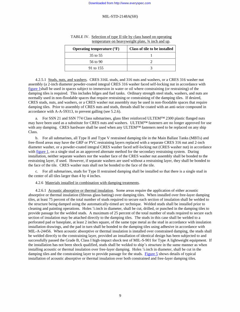
MIL-STD-2148A(SH)
9
TABLE IV. Selection of type II tile by class based on operating
temperature on heavyweight plate, ¾ inch and up.
Operating temperature (°F) Class of tile to be installed
35 to 55 1
56 to 90 2
91 to 155 3
4.2.5.1 Studs, nuts, and washers. CRES 316L studs, and 316 nuts and washers, or a CRES 316 washer nut
assembly (a 2-inch diameter powder-coated integral CRES 316 washer faced self-locking nut in accordance with
figure 1shall be used in spaces subject to immersion in water or oil where constraining (or restraining) of the
damping tiles is required. This includes bilges and fuel tanks. Ordinary strength steel studs, washers, and nuts are
normally used in non-floodable spaces that require restraining or constraining of the damping tiles. If desired,
CRES studs, nuts, and washers, or a CRES washer nut assembly may be used in non-floodable spaces that require
damping tiles. Prior to assembly of CRES nuts and studs, threads shall be coated with an anti-seize compound in
accordance with A-A-59313, to prevent galling (see 5.2.6).
a. For SSN 21 and SSN 774 Class submarines, glass fiber reinforced ULTEM™ 2300 plastic flanged nuts
may have been used as a substitute for CRES nuts and washers. ULTEM™ fasteners are no longer approved for use
with any damping. CRES hardware shall be used when any ULTEM™ fasteners need to be replaced on any ship
Class.
b. For all submarines, all Type II and Type V restrained damping tile in the Main Ballast Tanks (MBTs) and
free-flood areas may have the GRP or PVC restraining layers replaced with a separate CRES 316 nut and 2-inch
diameter washer, or a powder-coated integral CRES washer faced self-locking nut (CRES washer nut) in accordance
with figure 1, on a single stud as an approved alternate method for the secondary restraining system. During
installation, neither separate washers nor the washer face of the CRES washer nut assembly shall be bonded to the
restraining layer, if used. However, if separate washers are used without a restraining layer, they shall be bonded to
the face of the tile. CRES washer nuts shall not be bonded to the face of the tile.
c. For all submarines, studs for Type II restrained damping shall be installed so that there is a single stud in
the center of all tiles larger than 4 by 4 inches.
4.2.6 Materials installed in combination with damping treatments.
4.2.6.1 Acoustic absorptive or thermal insulation. Some areas require the application of either acoustic
absorptive or thermal insulation (fibrous glass batting) over damping tiles. When installed over free-layer damping
tiles, at least 75 percent of the total number of studs required to secure each section of insulation shall be welded to
the structure being damped using the automatically-timed arc technique. Welded studs shall be installed prior to
cleaning and painting operations. Holes ⅞ inch in diameter, shall be cut, drilled, or punched in the damping tiles to
provide passage for the welded studs. A maximum of 25 percent of the total number of studs required to secure each
section of insulation may be attached directly to the damping tiles. The studs in this case shall be welded to a
perforated pad or baseplate, at least 2 inches square, of the same type metal as the stud in accordance with insulation
installation drawings, and the pad in turn shall be bonded to the damping tiles using adhesive in accordance with
MIL-A-24456. When acoustic absorptive or thermal insulation is installed over constrained damping, the studs shall
be welded directly to the constraining layer, provided an installation of identical design has been subjected to and
successfully passed the Grade B, Class I high-impact shock test of MIL-S-901 for Type A lightweight equipment. If
the installation has not been shock qualified, studs shall be welded to ship’s structure in the same manner as when
installing acoustic or thermal insulation over free-layer damping. Holes ⅞ inch in diameter, shall be cut in the
damping tiles and the constraining layer to provide passage for the studs. Figure 5 shows details of typical
installation of acoustic absorptive or thermal insulation over both constrained and free-layer damping tiles.
Downloaded from http://www.everyspec.com

MIL-STD-2148A(SH)
10
4.2.6.2 Reflector and decoupler tiles. Acoustic reflector and decoupler tiles, such as Type AR-1, R-91, or AR
Type II in accordance with MIL-A-24485, do not provide damping to the structure to which they are attached.
Accordingly, it is necessary to install damping materials either on the reverse side of the structural member or under
the reflector tile. If the damping tile is installed on the reverse side of the structure, installation shall proceed in the
manner described in the appropriate section. If the damping tile is to be installed under the reflector tile, the
following steps shall be taken:
a. The damping treatment shall be selected based on the thickness of the structure to be damped without
regard to the reflector tile.
b. Stud length shall be increased to account for the thickness of the reflector tile.
c. Stud spacing may vary slightly due to the requirement to maintain a 1½-inch space between holes for studs
and the reflector tile edge. Attempts shall be made to conform as closely as possible to damping treatment stud
locations.
d. Reflector tiles shall replace restraining layers where applicable.
e. Reflector tiles shall be bonded to the outer side of the damping treatment in a manner similar to that for
bonding constraining layers to damping tiles.
f. Nut tightening and torque requirements for reflector tiles shall be followed when installing damping tile
under reflector tile.
4.2.6.3 Acoustic absorber tiles. Acoustic absorber tiles, such as Type AA-4, A-90 or AA Type II in accordance
with MIL-A-24486, do provide some measure of damping to the structure to which they are attached. Currently,
damping material is not applied to those areas where acoustic absorber tiles are installed.
4.2.6.4 Cableway hangers. In some instances, cableway hangers and light hangers have been welded to
damping treatment constraining layers. Repair and replacement of these installations shall proceed in a manner that
will not damage the damping treatment. Individual ship specifications shall be referenced as guidance for additional
applications of this technique. Design aspects such as shock, cost reduction, and repair of damping shall be
considered.
4.2.6.5 Air pollution regulations. Air pollution regulations to limit the amount of certain solvents are being
invoked in many states. For example, in California, the South Coast Air Quality Management District invokes
Rules 102 and 442 (previously Rule 66) to limit the use of solvents. These rules are applicable to paint in
accordance with MIL-DTL-24441, and all other epoxy coatings.
4.3 Submarines.
4.3.1 Main ballast tanks. Damping materials shall be installed on the inboard side of outer shell plates and on
one side of all transverses, longitudinals, and flats within the tanks. Materials installed in ballast tanks shall be
restrained to prevent detached material from falling to the bottom of the tanks and thus clogging dewatering ports.
Type II, Class 1 tiles, bonded to the steel structures and restrained or constrained as specified in tables I and II, and
Type V, Class 1 tiles restrained are used in this area. Type VI damping is also found in some submarine classes.
Damping shall be installed such that it will not interfere with transducers or sonar arrays. A typical installation is
shown on figure 6.
4.3.2 Tanks: bilge-collecting, main lubricating oil and lubricating oil settling, shaft lubricating oil sump, surge,
depth control, sanitary, and potable water. Damping materials are installed only on the dry sides of these tanks. In
some cases, the entire area of the tank is covered, depending upon accessibility and the possibility of resonance
excitation of the structures. The areas on these tanks to which damping material is applied usually are inside the
pressure hull and thus generally are at temperatures above that of seawater temperature. However, the fluids in these
tanks can become cold under some operating conditions. Thus, the average surface temperature of the steel shall be
used in determining the Class of Type II tile to be used to damp these tanks. Classes of Type II tile shall be in
accordance with tables III and IV. Steel plate in these tanks may range in thickness from ⅛ inch to over 1 inch,
depending on the type of tank. Free-layer Type II tiles weighing 2.8, 3.1, or 4.5 lb/ft², or constrained with steel
plate, depending on the thickness of the steel plate to be damped, shall be used in these areas. Type II tile weight
and constraining layer thickness shall be in accordance with tables I and II. Typical installations are shown on
figures 3 and 4.
Downloaded from http://www.everyspec.com
MIL-STD-2148A(SH)
11
4.3.3 Superstructure, fairwater, and other free-flooded spaces. Only the inboard side of shell plates
(non-pressure hull), fairwater plates, and one side of all transverse and longitudinal bulkheads and flats, and supports
shall be damped. The extent of installation depends on the design of the particular ship. The requirements for
damping material are the same as those used in ballast tanks, except that the tiles shall be restrained only in those
areas where their dislodgement could damage sensitive equipment.
4.3.4 Hull frames. The webs of hull frames that support machinery or noise-critical equipment foundations
usually are damped for a distance of at least 3 feet on either side of the foundation attachment point. Damping
materials shall be installed only on one side of the web. If webs on frames are less than ¾ inch, damping shall be in
accordance with table II; however, if the webs or frames are ¾-inch thick or greater, damping treatment shall consist
of Type II tiles weighing 2.8 lb/ft², constrained with a steel plate in accordance with table I. Figure 7 provides
installation details for this type of damping treatment. It is not necessary to cut damping tiles on the web to conform
to the frame curvature, and they may be installed as shown on figure 2 (see 4.2.2).
4.3.5 Machinery or noise-critical equipment foundations, bulkheads, and girders. Damping material shall be
installed on only one side of all members acting as machinery or noise-critical equipment foundations when
vibrational energy can be transmitted to the foundation. It also is applied to one side of the bulkheads, girders, and
decks, except those shielded with lead, that support machinery, noise-critical equipment, or foundation attachments
that will transmit vibration to the hull. Type II tiles shall conform to the weights and the constraining layer
requirements of tables I and II. Classes of Type II tile shall be selected based on the average surface temperature, as
specified in tables III and IV. For example, the reduction gear casing and the foundation supporting the reduction
gear typically requires Type II, Class 3 tile.
4.3.6 Platform decks and supporting beams. Damping material shall be installed on the underside of platform
decks, except those decks that have ceramic tile or trowel-on deck covering installed on the top side. Type II tile in
accordance with tables III and IV shall be used in these areas dependent upon average surface temperature. Figure 8
shows a typical installation of damping material on the underside of a platform deck. A typical installation on a
deck beam supporting a platform deck is shown on figure 9.
4.3.7 Sonar domes. Requirements for damping materials are specified in the particular submarine class
specifications and installation plan drawings. Type II, Class 1 tiles and Type V, Class 2 tiles are used in the sonar
access trunk, and are constrained.
4.4 Surface ships.
4.4.1 Hull, frames, longitudinal stiffeners, and keel. Damping material shall be installed on the inboard side of
the hull, below the waterline, on one side of webs of frames, one side of longitudinal stiffeners and on the top and
one side of the keel. If the structures to be damped are in the vicinity of the sonar dome, Type III plastic tiles shall
be used. The fore and aft distance from the sonar dome to which structures shall be damped depends on the location
of the sonar dome and the distribution of machinery in spaces above the dome. When the dome is located at the bow
of the ship, damping material normally shall be installed above the dome and to at least the first watertight bulkhead
aft of the dome. If the dome is positioned aft of the bow, damping material normally is applied to at least the first
watertight bulkheads fore and aft of the dome. A single layer of Type III tiles shall be installed on steel plate up to
½ inch in thickness; two layers of Type III tile shall be applied to plates of greater thickness. If the structure to be
damped is in or near machinery spaces, Type II tiles are normally used. The weight of tile to be applied for various
thicknesses of steel plate to be damped shall be in accordance with tables I and II. Selection of the class of Type II
tile to be applied based on constraining layer and operating temperature requirements, if any, shall be in accordance
with tables III and IV.
4.4.2 Bulkheads and platform decks. Within the space limits delineated in 4.4.1, damping materials shall be
installed on one side of all bulkheads and on the underside of platform deck plating, except decks that have ceramic
tile or trowel-on deck covering on the top side of the plating. The types of damping materials discussed in 4.4.1
shall be installed on these structures; Type II tiles in or near machinery spaces and Type III tiles in vicinity of sonar
domes.
Downloaded from http://www.everyspec.com

MIL-STD-2148A(SH)
12
4.4.3 Surface ship machinery foundations. Damping materials are installed on one side of all members located
in the vicinity of sonar domes as delineated in 4.4.1, which can impart vibrational energy to the hull. Type III
plastic tiles are normally installed on steel structure up to 11⁄16 inch in thickness. For foundations of greater thickness,
constrained Type II, Class 2 tiles weighing 2.8 lb/ft² shall be used. Damping materials also are installed on one side
of selected machinery foundation members located within machinery spaces as outlined in ship specifications.
Type II, Class 2 tiles are normally applied in these areas. For areas that operate at temperatures above ambient room
temperature, such as the reduction gear casing and foundation, Type II, Class 3 tiles are used.
4.4.4 Fuel oil and salt water tanks. Damping material shall be installed on one side of the boundaries of oil and
salt water tanks located in the vicinity of sonar domes within the limits delineated in 4.4.1. Where practicable,
damping material shall be installed on the dry side of the tanks. Type III plastic tiles shall be installed on these
structures. Damping material shall not be installed inside JP-4, JP-5, lubricating oil, or hydraulic system tanks.
However, Type III damping materials may be installed inside tanks containing diesel oil, distillate fuel oil, Navy
special fuel, oil, or salt water, provided they are protected by a paint coating from deterioration due to immersion in
the liquids. A single layer of Type III tiles shall be installed on steel plate up to ½ inch in thickness. Two layers of
Type III tile shall be installed on plates of greater thickness. Type II tiles shall be applied to these tanks when
located in machinery areas, and do not require protection against immersion.
4.4.5 Sonar domes. Damping and special acoustic materials, for example decouplers, shall be installed on
specified interior surfaces of surface ship sonar domes. The type and extent of materials to be applied are normally
contained in individual ship specifications.
4.5 General health and safety requirements. This section addresses minimum health and safety aspects of
applying damping materials with epoxy paints and adhesives. Information that applies to a particular type of
damping material is included with the specific material installation procedures. In addition to the health and safety
requirements provided herein, applicable local documents, facility requirements, State and Federal regulations may
also apply.
4.5.1 General health hazards. Several aspects of tile installation expose personnel to conditions and situations
that represent actual or potential danger to themselves and to others in the area. The frequent necessity to use toxic
and flammable materials, pressurized equipment, ladders, scaffolding, and rigging always represents a potential
hazard. Hazards also may be caused through ignorance or carelessness of the operator. The general requirements
for personal protective equipments shall be in accordance with 29 CFR 1910.
4.5.1.1 Paint materials. Most paint materials are hazardous to some degree. The majority of paint materials are
flammable, toxic, and can irritate the skin. Paint shall only be used in well ventilated areas. Prolonged contact with,
or inhalation of, cleaning solvents shall be avoided. Use near heat or open flame shall be avoided. Ventilation
(see 4.5.2.7.9) and skin protection (see 4.5.2.9.2) shall be provided in order to avoid the following health risks
associated with paint materials:
a. Epoxy paints: Uncured epoxy resins and polyamide, amine, or polyamine curing agents in epoxy paint
systems such as those in accordance with MIL-DTL-24441 have been shown to cause dermatitis. Major problems in
handling epoxy systems occur as a result of the caustic nature of the amine curing agents. These agents may cause
burns (pH of 13 to 14) and sensitization. Inhalation of amine fumes may cause mucous membrane irritation and
asthmatic symptoms. Overexposure to the solvents in these systems may cause headache, nausea, dizziness, and
loss of consciousness. Solvent content includes N-butyl alcohol, naphtha, and ethylene glycol monoethyl ether.
b. Antifouling paints: Antifouling paints are irritating to the skin. The solvent vapors, at low concentrations,
can cause mucous membrane irritation, and at high concentrations may result in drowsiness and loss of
consciousness. Chemical content may include methyl isobutyl ketone, xylene, and tricresyl phosphate.
4.5.1.2 Adhesive materials. Uncured epoxy resin, hardener, and mixed adhesives can cause dermatitis and
sensitization. Odors from the adhesive component are offensive to some individuals. Ventilation (see 4.5.2.7.9) and
skin protection (see 4.5.2.9.2) shall be provided in order to avoid the health risks associated with uncured epoxy
materials.
Downloaded from http://www.everyspec.com

MIL-STD-2148A(SH)
13
4.5.1.3 Damping materials. In general, damping materials are made from thermoplastic vinyl, epoxy, or
molded rubber. They do not represent severe health hazards under normal circumstances. Graphite dust may issue
from tile cutting operations, and this may be a respiratory irritant or create problems for electric motors or capacitors
in the area. However, welding or burning near Type VI damping tiles (near the aramid fiber laminate of Type VI
damping tiles) may release toxic gases if heated above 445 °F. The rubber base can be damaged when heated above
200 °F. Hot work that would raise the temperature of the Type VI tile above 180 °F shall not be permitted. Welding
shall not be attempted at less than 2 inches from the tiles, or at a greater distance in accordance with local
instructions.
4.5.1.4 Surface preparation materials. Personnel shall be thoroughly familiar with local safety precautions and
rules. Preparation of a surface for painting and bonding often requires the use of solvents and cleaners, which will
harm the skin unless used with care. Paint removers are very irritating to the skin and some are highly toxic. High
pressure abrasive blasting methods can be hazardous. Pressures as low as 10 to 15 pounds per square inch (lb/in²)
have been known to cause serious injuries. Carelessness during abrasive-blasting operations can also result in lung
disease after continued exposure. Steam cleaning procedures employ both high heat and pressure, and can be
hazardous to the operator and personnel in the vicinity if not properly handled.
4.5.2 General safety measures. Potential hazards in all tile installation operations make a continuing and
enforced safety program essential. Safety procedures will provide protection against the three major types of
hazards: accidents, fire, and health. Personnel shall be thoroughly familiar with local precautions and safety rules.
Each worker shall adhere to established precautionary programs.
4.5.2.1 Working environment. During coating operations, all confined spaces shall be properly ventilated in
accordance with 29 CFR 1915.15. The working environment shall be examined before sending workers into any
work area. Hazards, such as poor ventilation and noxious vapors, shall be considered. Before a worker is allowed to
enter such an area, he or she shall be protected by devices that will allow him or her to work in safety. Special
action is required if:
a. Oxygen concentration is less than 19.5 percent, or
b. Combustible gas meter readings show differences between the work space and outside air, or 10 percent
below lowest explosive limit (LEL), or
c. It is known or suspected that the work space may contain toxic vapors or gases that are not practical to
measure with equipment on hand (such as distillate fuels, kerosene, or Navy standard fuel oil).
If any of the three mentioned conditions exist in the working environment, ventilation or respiratory protective
equipment shall be provided. Ventilation shall consist of outside air and shall be provided at the minimum rate
specified in table V, but no less than that needed to provide a safe atmosphere. Otherwise, respiratory protective
equipment shall be provided. When exhaust systems are used, such as in a tank, the system shall take suction from
the bottom of the tank or a similar area in which the work is being done. The potential of a still area or pocket shall
be considered. Individuals shall never work alone in a hazardous area. The discharge from exhaust systems shall be
arranged so that contaminated air will not create health hazards in surrounding areas. Ventilation shall be continued
for at least 1 hour after the coating operation has been completed and until vapor concentrations remain below
10 percent of the LEL. Personnel shall be provided with suitable eye protection (safety goggles, chemical safety
goggles), appropriate protective clothing such as hard hats and safety shoes, and impervious clothing, as necessary.
TABLE V. Minimum ventilation rates.
Space volume, cubic feet Ventilation rate, air change
Less than 2,000 2 minute air change
2,000 to 4,000 3 minute air change
4,000 to 10,000 5 minute air change
Greater than 10,000 10 minute air change
Downloaded from http://www.everyspec.com

MIL-STD-2148A(SH)
14
4.5.2.2 Respiratory protection. Personnel shall wear the proper type of face mask in hazardous areas. Devices
shall be approved by the National Institute for Occupational Safety and Health (NIOSH) and Mine Safety and
Health Administration (MSHA).
4.5.2.2.1 Types of respirators. The most important types of respirators are as follows:
a. “Air purifying” cartridge dust respirators, for protection against dusts present when sanding. These
respirators contain filters only.
b. “Air purifying” chemical cartridge respirators, for protection against organic solvent vapors. These
respirators contain activated carbon cartridges that absorb the vapors.
c. “Supplied-Air-Respirator (SAR),” for use in closed areas where ventilation cannot be supplied.
4.5.2.3 Eye protection. Safety eyewear, safety glasses, and chemical splash goggles shall be worn in areas
where there is a possibility of particulate, mists, vapors, solvents, and adhesives contacting eyes. This may occur
during operations involving blasting, sanding, spraying solvent, wiping, or adhesive mixing and spreading. Safety
eyewear shall be kept clean and readily available. Safety eyewear lenses shall be unbreakable glass or plastic, and
allow peripheral as well as straight-ahead vision.
4.5.2.3.1 Eyewashes. Emergency eyewashes shall be in proximity to operations where eye irritation may
occur. Portable eyewashes shall be available wherever fixtures are not feasible. A portable eye wash facility shall
be capable of supplying as least 0.4 gallon (1,500 milliliters [mL]) of potable water per minute for 15 minutes.
Capability for flushing both eyes simultaneously shall be provided.
4.5.2.4 Protective clothing. Personnel shall wear clean clothing, covering themselves as much as possible, to
avoid skin contact with paints, solvents, or uncured adhesives. Safety helmets or hoods shall be worn when using
abrasive blasting media. Hard hats and steel-toed safety shoes shall be worn wherever there is any possibility of
danger from falling objects. Shoes shall have non-skid rubber soles when working in enclosed spaces, or where
flammable vapors may be present.
4.5.2.5 Safety precautions for abrasive blasting. The safety precautions specified in 4.5.2.5.1 through 4.5.2.5.6
are directed towards preventing injury and property damage. They also shall be followed to preclude inadvertent
introduction of abrasive blasting materials into ship’s spaces, into open ship’s equipment or systems, and onto
unprotected equipment while conducting abrasive-blasting operations on and in the vicinity of naval ships.
4.5.2.5.1 Preventive measures. Abrasive blasting within the ship shall not be accomplished until steps have
been taken to positively prevent contamination and spread of abrasives and dust to adjacent compartments,
machinery, and equipment.
4.5.2.5.2 Requirements prior to blasting operations. The ship’s force and all shops shall be notified of when
and where abrasive-blasting operations are to be accomplished. Shops and the ship’s force shall take the following
precautions to protect equipment and structures:
a. Drop cloths and masking shall be used to prevent damage from the abrasive material.
b. Temporary divisional shields and other sealing or blanking-off measures shall be used to prevent abrasives
from entering machinery, pipes, seawater inlets, and pump wells through various openings.
c. Where remote service connections provide water or ventilation, such as seawater for the auxiliary seawater
system while the ship is in drydock, the inlet to that connection shall be located and shall be arranged such as to
prevent the entry to blasting contaminants.
d. Additional sealing and protective precautions shall be taken to the extent necessary to protect adjacent
ships, buildings, and stores. Abrasives and dust can enter ships through open sea valves, hatches, ventilation
systems, temporary openings, and normal entry ways frequently opened and closed, or entry ways forced to remain
open due to other work. If there is any possibility that abrasives can enter a ship even though all possible
precautions are taken, critical surfaces and parts of machinery, including electric and electronic equipment, shall be
positively sealed or otherwise protected. Machinery components such as reduction gears, open boilers, hotwells,
and turbines in various stages of disassembly are especially vulnerable. Personnel in or near the blasting area shall
be warned of possible hazardous conditions. In all circumstances, close cooperation between ship and shipyard
personnel is required.
Downloaded from http://www.everyspec.com

MIL-STD-2148A(SH)
15
4.5.2.5.3 Pre-abrasive blasting inspection. The entire area to be blasted shall be visually inspected. Heavily
rusted or corroded areas, damaged metal, and holes in structure or piping shall be investigated for further technical
examinations and possible repair prior to commencement of blasting operations. Abrasive blasting hoses routed
through compartments shall be identified by a sign (appropriately marked) posted in each compartment that warns
against damaging the hoses.
4.5.2.5.4 Post abrasive blasting inspection. The entire area shall again be visually inspected for pits, scabs, and
scars. Suspected wall thickness reductions shall be reported for further technical examination.
4.5.2.5.5 Abrasive blasting protective equipment. Blasters shall wear hoods and airline respirators or air
helmets of the positive pressure type. Abrasive-blast operator shall wear a NIOSH/MSHA approved
abrasive-blasting respirator, Type CE (supplied-air with protective hood). The air supplied to the respirator shall
meet the standards for breathing air in accordance with 29 CFR 1910.134. Other mandatory clothing includes
rubber or leather gauntlet gloves, safety shoes, and coveralls. Personnel other than blasters, including machine
operators and personnel engaged in work in the vicinity of abrasive-blasting operations, shall wear full eye
protection and NIOSH/MSHA approved respirators with half or full face piece and filters approved for protection
against dusts and mists having a time weighted average not less than 2 million particles per cubic foot. Full face
piece pressure-demand supplied air respirators may be required depending on abrasive blast grit used, ventilation,
rate of blasting, blast gun, and so forth. NIOSH-approved dust respirators. Approved ear protectors shall be worn
wherever the airborne noise level is above 85 decibels (A-weighted [dBA]). Both ear plugs and ear muffs
(double protection) shall be worn if the noise level exceeds 96 dBA, in accordance with MIL-STD-1474.
4.5.2.5.6 Staging. Staging shall be stable and correctly positioned for safety, convenience, and comfort of the
blast operator.
4.5.2.6 Safety precautions for mixing paint.
4.5.2.6.1 Fire prevention precautions. Smoking, open flame (such as matches and torches), and hot work are
prohibited in or near the area where paint, varnishes, lacquers, and their solvents are mixed. Spilled paint or
solvents shall be wiped up immediately to reduce fire and vapor hazards. Rags or other items used for paint clean-
up shall be placed in a separate container, having a closed top, for disposal.
4.5.2.6.2 Accidental ignition. Extreme care shall be taken by persons working with solvent-based coatings to
eliminate all possible sources of ignition (such as matches, cigarette lighters, and steel buckles) from their persons.
Working personnel shall wear canvas boots over their shoes or shall wear rubber footwear when standing on steel
decking. Plastic clothing shall not be worn. Loose steel objects shall be removed from the immediate vicinity of
coating operations.
4.5.2.6.3 Electrical equipment. Electrical equipment in rooms where extensive paint mixing operations are
performed shall be installed in accordance with NAVSEA Standard Item 009-32. Explosion-proof lamps with
shatterproof lenses shall be used.
4.5.2.6.4 Personnel protective precautions. These precautions apply to ship paints in general. Skin contact, eye
contact, ingestion, and inhalation of mists or vapors in excess of the threshold limit value shall be avoided. A Navy
Environmental and Preventive Medicine Unit or a Navy Medical Center shall be consulted for surveying if doubt
exists on acceptability of personnel protective procedures. Shipyard personnel shall contact an Occupational Safety
and Health Office representative for surveys or technical advice regarding protective equipment.
4.5.2.6.5 Sensitivity, allergic reactions, and pulmonary disorders. Persons handling paints, adhesives, and
solvent materials shall avoid contact with the skin and eyes or inhalation of mist or vapors. No smoking, food, or
drink shall be allowed in the paint area. When handling paints and solvents, care shall be exercised to wash hands
before eating, drinking, smoking, or using the toilets. Personnel with a history of chemically induced chronic skin
disease, allergies, or asthma shall not work with paint compounds and solvents. The advice of a physician should be
sought where there is doubt about an individual’s medical suitability for this type of work.
Downloaded from http://www.everyspec.com

MIL-STD-2148A(SH)
16
4.5.2.6.6 Vinyl paints. Personnel mixing these paints shall wear solvent-resistant synthetic rubber gloves and
apron. Sleeves shall be kept rolled down. NIOSH-approved half-mask respirator with organic vapor cartridge shall
be required when air sampling data indicates solvent concentrations in excess of the exposure limit values, or when
it is reasonable to assume that solvent vapor concentrations cannot be controlled by ventilation and are expected to
exceed the threshold limit value for the solvent involved.
4.5.2.6.7 Epoxy paints. Epoxy paints, such as those in accordance with MIL-DTL-24441, are used in this
standard. Certain epoxy paints are considered to be acceptable alternatives to MIL-DTL-24441, and may be
substituted for MIL-DTL-24441 where referenced in this document (see 5.2.7 for details on substitution of
coatings). NAVSEA Standard Item 009-32 provides additional guidance for application. Epoxy paints are used as
part of the adhesive system. In general, one to three coats of paint are applied prior to bonding of damping titles.
The vinyl paint precautions of 4.5.2.6.6 also apply to epoxy paints.
4.5.2.6.7.1 Dermatitis and allergy hazard. As a consequence of ingredients used to provide superior adhesion
and high anti-corrosive performance, epoxy paints present greater health hazards than many conventional paints.
This requires strict adherence to safety precautions. If epoxy coatings contact the skin, skin shall be cleaned
immediately with soap and water. Solvents shall not be used, as they can thin out and spread the paint over the skin,
permitting deeper penetration of the paint into the skin and thereby increasing the hazard of irritation or allergic
reaction.
4.5.2.6.7.2 Epoxy solvents. Epoxy solvents contain ingredients, such as ethylene glycol monoethyl ether, that
are readily absorbed into the body through the skin. Particular attention to skin protection is necessary to prevent
skin absorption from adding significantly to overall exposure, especially during cleaning of equipment.
4.5.2.7 Safety precautions for paint application. Safety precautions for mixing shall also apply to application.
Additional requirements are presented in this section.
4.5.2.7.1 Danger area. A danger area for each painting operation shall be defined by the local activity and
clearly delineated by signs. A danger area is that area in which there is a possibility that explosive mixtures may
collect.
4.5.2.7.2 Application by brush or roller. Precautions for brush or roller application are the same as those for
mixing, except that there are increased potential hazards from flammable or toxic solvents. Additional ventilation
may be needed to comply with requirements for flammable material control. Additional ventilation or use of
respirators may also be needed.
4.5.2.7.3 Vinyl and epoxy paints. Personnel applying these paints by brush or roller shall avoid skin contact
with the paint or its components by wearing solvent-resistant synthetic rubber gloves and apron. Sleeves shall be
kept rolled down. A face shield or chemical safety goggles shall be worn to protect the face and eyes. Protective
cream in accordance with A-A-50169 shall be used on exposed parts of the skin to act as a barrier and to facilitate
cleaning after painting. Local exhaust or supply ventilation shall be used to control personnel exposure to solvent
vapors.
4.5.2.7.4 Application by spray. The application of paints, varnishes, lacquers, enamels, and other flammable
liquids by the spray process is more hazardous than brush applications because of the volume and concentration of
the work and because spraying produces a residue that is flammable and deposits that are subject to spontaneous
ignition. Health hazards due to the presence of potentially harmful substances may also be present in paint spraying
operations. Precautions for paint spraying include those for mixing and brushing as well as the additional
requirements of this section.
Downloaded from http://www.everyspec.com

MIL-STD-2148A(SH)
17
4.5.2.7.5 Fire prevention precautions. Precautions in addition to those for brushing or mixing are necessary to
prevent static sparks and to prevent excessive concentrations of flammable solvents. The flash points of vinyl and
epoxy paints are 65 °F and 95 to 180 °F respectively, and can readily form explosive atmospheres in confined
spaces. Danger areas shall extend at least 50 feet from the painting operations and may include an entire drydock
for extensive painting with highly flammable paints. The vicinity of the painting operation shall be roped off and
“DANGER AREA” signs posted to alert personnel of the hazard. These signs are to stipulate the danger area and
that smoking, hot work, or open flames are prohibited. Electrical leads within the danger area shall be sealed and
equipment requiring grounding shall be grounded. During spray painting operations, fire extinguishing equipment
shall be in the ready condition.
4.5.2.7.6 Application in confined spaces. The additional precautions specified in 4.5.2.7.7 through 4.5.2.7.14
shall be observed when coating confined spaces, such as tanks.
4.5.2.7.7 Explosion-proof lamps. Explosion-proof lamps with shatterproof lenses shall be installed. Lights
shall be completely and properly assembled in operable condition prior to installation in the danger area. There shall
be no bulb replacement or repair of any lights within the danger area. Portable lights shall be hung on stiffeners by
means of spark-proof hooks and shall never be wrapped around or draped over supports.
4.5.2.7.8 Gas-free testing. Periodic tests to ensure safe gas-free working conditions shall be conducted. The
gas-free engineer shall conduct the initial test, with monitors conducting the follow-up tests. Gas testing shall
continue as necessary during painting operations to detect dangerous accumulations of hazardous vapors.
4.5.2.7.9 Ventilation. During coating operations, tanks shall be properly force-ventilated. Where the venting
of the vapors given off by the coatings will create an explosion hazard outside the compartment being coated, water
curtains shall be installed at the vents. Also, ventilation shall be continued for at least 1 hour after the coating
operation has been completed and until vapor concentrations remain below 10 percent of the LEL. Brush painting
procedures shall comply with general brush painting precautions.
4.5.2.7.10 Personnel protective precautions. Spray painting shall require all the precautions of brush painting,
with additional measures to protect personnel from atomization of larger quantities of material.
4.5.2.7.11 Protective clothing. Spray painters shall wear protective garments that fit snugly at the ankles, neck,
and wrists. They shall wear gloves and approved airline respirators while spraying in confined spaces, when mixing
dry colors, or using other finishing materials that create flammable vapors. They should never inhale the mist from
the spray gun.
4.5.2.7.12 Showers. Where paint-spraying operations are conducted extensively, showers shall be available,
and the employees shall use them after every shift.
4.5.2.7.13 Cleaning spray guns. Spray guns, paint containers, and hose shall be thoroughly cleaned after use,
but shall never be cleaned in confined areas.
4.5.2.7.14 Epoxy paints. Personnel spray painting with MIL-DTL-24441 paints or other epoxy paints in other
than approved spray booths shall wear coveralls, gloves, and a NIOSH-approved airline respirator that provides
full-face coverage. The air supply to the respirator shall be approved as breathing air. Approved goggles shall be
worn, except where eye protection is provided by air-supplied respirators or hoods. Exposed areas of the skin shall
be covered with protective cream. The same precautions apply to application of vinyl paints, except
NIOSH-approved organic vapor respirators may be substituted for airline respirators when working in open exterior
spaces. Where these coatings are applied overhead or on surfaces above waist level of the personnel, approved
hoods that completely protect the head, face, and neck shall be worn.
Downloaded from http://www.everyspec.com

MIL-STD-2148A(SH)
18
4.5.2.8 Safety precautions for adhesive mixing and application. The epoxy adhesives used for the installation
of damping materials are not dangerously flammable. Extra-rigid fire precautions, like those required for painting,
are not required for this work. Ensure epoxy adhesives are not mixed or used within 35 feet of hot work operations.
The adhesives are irritating to the skin. Frequent or prolonged exposure of the skin to the epoxy adhesive shall be
avoided; serious injury may result if any is allowed to come into contact with the eyes. Special precautions are as
follows:
a. If skin cream is used, it shall be rubbed over hands and wrists before working with epoxy adhesives. If the
skin cream is used, wait until the cream has been absorbed uniformly before donning gloves. Rubber gloves shall be
worn in all cases. Plastic face shields shall be worn for protection of the eyes. The adhesive shall be mixed only in
a well-ventilated area. Skin that comes into contact with any component of the adhesive shall be washed
immediately with soap and water.
b. Personnel with a history of chronic skin disease, allergies, or respiratory ailments shall not work with
adhesive compounds and solvents. Persons handling these materials shall avoid contact with the skin and the eyes,
or inhalation of vapors. No food or drink shall be allowed in the work area. When handling adhesives and solvents,
care shall be exercised to wash hands before eating, drinking, smoking, or using the toilets. Sensitivity of personnel
shall be reported to the medical department.
c. Epoxy adhesives do not produce toxic fumes, but ventilation shall be provided in work spaces to prevent
discomfort to workers from unpleasant odors given off.
4.5.2.9 Cleaning with degreasing solvents. When solvents are used to clean tools, damping materials, and both
painted and unpainted surfaces, protective measures applicable to the solvent used shall be followed. Protective
measures may include, but are not limited to, forced-air ventilation for confined spaces, the use of effective
respirators, eye protectors, and protective gloves for all personnel in the area.
4.5.2.9.1 Eye protection. Eye protection shall be worn by all personnel when working with or near solvent
including PF-145HP degreaser, IPA or equal (see 3.15). When using any solvent, including PF-145HP degreaser,
IPA or equal (see 3.15), chemical goggles or safety glasses with face shield shall be worn.
4.5.2.9.2 Skin protection. Protective (nitrile rubber or fluorocarbon) gloves shall be worn by personnel
working with PF-145HP degreaser, IPA or equal (see 3.15) to avoid drying and cracking of skin. While using
PF-145HP, or equal (see 3.15) for washing/wiping, gauntlet neoprene gloves shall be worn.
5. DETAILED REQUIREMENTS
5.1 General. Detailed requirements are provided for surface preparation, stud welding, painting, adhesive
application, and damping tile installation. All steps required to prepare and preserve surfaces and to install damping
tiles are included. See 5.2 for details common to many damping tile installations such as surface preparation, stud
welding procedures, choosing the appropriate coating, checking for amine bloom, adhesive choice and preparation,
antifouling coating, etc. See 5.3 through 5.8 for specific steps unique to each type and class of damping tile and
details for installation of studs, nuts, washers, and restraining or constraining layers, where required. See 5.9 and
5.10 for damping tile repair, maintenance, and inspection.
Downloaded from http://www.everyspec.com

MIL-STD-2148A(SH)
19
5.2 Common requirements. The surface (substrate) to which the tiles are to be applied shall be blast cleaned to
a near-white metal surface finish, and primed with an epoxy protective coating system, or one of the alternative
coatings, as specified in 5.2.7. Surface preparation, cleaning, and painting shall be in accordance with local
instructions, except as noted herein. Abrasive blasting to a near-white metal surface finish shall be in accordance
with the definitions and procedures specified in SSPC-SP 10, and verified against pictorial standard SSPC-VIS 1.
Prior to blasting, an inspection for chloride residue contamination shall be conducted in accordance with local
instructions in all spaces except dry spaces and remove as necessary. Excessive rust scale may be removed by hand
or power impact tools. Such cleaning shall be in accordance with SSPC-SP 2 or SSPC-SP 3. A visual inspection
shall be conducted in accordance with local instructions to ensure conformance to surface cleanliness requirements
prior to further surface preparation. Any oil, grease, or waxy contamination present on the steel shall be removed
with a clean cloth wetted with solvent. If condensation is observed on the metal surfaces, the metal shall be warmed
until the condensation disappears. This condition shall prevail from the start of abrasive-blasting operations until all
tiles are installed and the adhesive cured, unless there is a delay between painting and tile application. In that case,
see below for details on steps that shall be taken for surface preparation and conditions to be maintained in the case
of aged paint. In general, a maximum of 4 hours should elapse between the time surface preparation ends and the
preservation coating begins. The primer, or one of the approved alternative coatings, shall be applied prior to the
formation of rust on the completed near-white surface finish. Should rust begin to form before the primer is applied,
the blast-cleaning procedure shall be repeated and the primer coat applied to a near-white surface. Cleaning of
previously painted surfaces shall be as follows:
a. If the metal surface to be tiled has been previously coated (prior to current availability) with one of the
protective coating systems listed and the coating is in generally sound condition, it may only be necessary to clean
and abrade the coating, except for ship structural surfaces defined as critical coated areas, which shall be cleaned as
specified below. In these cases, Ultra High Solids coatings are the preferred coatings.
b. The acceptable painted surface shall be sweepblasted in accordance with SSPC-SP 7 to remove surface
gloss, any loose paint, or contaminants. Bare metal spots shall be painted, or primed and painted, as required for the
specific coating to be applied (see 5.2.7). Areas still covered with paint shall be coated to a total DFT as specified in
5.2.7.
5.2.1 Surface preparation – dry spaces.
5.2.1.1 Cleaning steel surfaces in dry spaces. Steel surfaces of dry spaces include foundations, bulkheads,
platform decks, dry side of tanks, hull, keel, frames and underside of platform decks, and all other non-flooded
spaces. Oil, grease, or waxy substance, if present, shall be removed by wiping the contaminated area with a cloth
wetted with solvent (see 3.15). The solvent shall be poured onto a clean, lint-free cloth; the cloth shall not be dipped
into the solvent container. The surface shall be wiped with the solvent wetted cloth, continuously turning the cloth
to present a clean section of the cloth against the surface. The surface shall be deemed clean when the cloth remains
clean when wiped against the surface. The solvent shall be allowed to flash off completely, but for no less than
30 minutes prior to conducting the next step in the damping installation process. An inspection shall be conducted
using SSPC-SP 1 to ensure surface cleanliness prior to surface preparation. The steel surface shall be cleaned to
near-white metal by abrasive blasting. All blasted steel surfaces shall meet the surface condition of SSPC-SP 10.
The average surface profile shall be 2 to 4 mils, with no individual profile readings less than 1 mil or greater than
5 mils. Where abrasive blasting is impractical due to proximity of installed machinery or equipment, the surfaces
may be mechanically cleaned. In that case, the surface cleanliness shall conform to SSPC-SP 11. The surface
profile shall be 2 mils minimum.
Downloaded from http://www.everyspec.com

MIL-STD-2148A(SH)
20
5.2.2 Surface preparation – wet spaces.
5.2.2.1 Cleaning of steel surfaces in wet spaces. Steel surfaces of wet spaces include inside ballast and trim
tanks and inside all other flooded spaces (sonar domes, super-structure spaces and fairwaters, bilges, bilge wells,
peak tanks, and sumps). An inspection for chloride residue contamination shall be conducted in accordance with
local procedures and any contamination removed as necessary. A visual inspection in accordance with SSPC-SP 1
shall be conducted to ensure surface cleanliness prior to further surface preparation. Any oil, grease, or waxy
contamination present on the steel shall be removed with a clean cloth wetted with solvent (see 3.15). The solvent
shall be poured onto a clean, lint-free cloth; the cloth shall not be dipped into the solvent container. The surface
shall be wiped with the solvent wetted cloth, continuously turning the cloth to present a clean section of the cloth
against the surface. The surface shall be deemed clean when the cloth remains clean when wiped against the
surface. The solvent shall be allowed to flash off completely but for no less than 30 minutes prior to conducting the
next step in the damping installation process. The steel surfaces, including those with galvanized coatings, shall be
cleaned to near-white metal by abrasive blasting. For galvanized surfaces, the metal under the galvanized coating
shall be blasted to near-white metal. The surface cleanliness shall conform to SSPC-SP 10. The average surface
profile shall be 2 to 4 mils, with no profiles less than 1 mil or greater than 5 mils. Where abrasive blasting is
impractical due to proximity of installed machinery or equipment, the surfaces may be mechanically cleaned as
specified in SSPC-SP 11. The surface profile shall be 2 mils minimum.
5.2.3 Surface preparation – gear cases.
5.2.3.1 Gear cases and structures that operate at temperatures of 80 to 155 °F. The steel surfaces shall be
prepared in the same manner as in 5.2.1. If abrasive blasting is impractical, dirt, scale, or other dry contamination
shall be removed by vigorous brushing with a steel wire brush followed by thorough sanding with 60- to 120-grit
emery paper, followed by solvent wiping as detailed in 5.2.2.1.
5.2.4 Surface preparation – non-steel surfaces.
5.2.4.1 Non-steel surface cleaning. Non-steel surfaces such as aluminum alloys, CRES, and nickel-copper
alloys that require damping shall be cleaned of grease and oil by wiping with a clean cloth wetted with solvent
(see 3.15). The solvent shall be poured onto a clean, lint-free cloth; the cloth shall not be dipped into the solvent
container. The surface shall be wiped with the solvent wetted cloth, continuously turning the cloth to present a clean
section of the cloth against the surface. The surface shall be deemed clean when the cloth remains clean when
wiped against the surface. The solvent shall be allowed to flash off completely, but for no less than 30 minutes prior
to conducting the next step in the damping installation process. The surface can then be abrasive blasted. The
abrasive blasting operation shall provide a uniformly roughened surface over the entire area to be damped
(smooth or polished areas must be eliminated). (Note: Blasting abrasive previously used to remove copper-based
antifoulant paint shall not be re-used for abrasive blasting aluminum alloys.) Time between abrasive blasting and
priming shall be minimized.
5.2.4.2 GRP surface cleaning. The GRP surface shall be washed with solvent (see 3.15) to remove any mold
release and surface contaminants. The GRP surface shall then be sanded with 80- to 120-grit emery paper to remove
any mold release coatings used during the manufacturing process. The surface shall then be rewashed with the
solvent and solvent shall be allowed to flash off completely, but for no less than for 60 minutes. The GRP surface
shall then be abrasive blasted with 36-grit aluminum oxide or garnet abrasive at low pressure (40-80 lb/in²,
depending on nozzle size and cubic feet of air per minute) to remove any remaining mold release or surface
contaminants and achieve a blast profile of 2-3 mils. Care shall be taken to prevent damage to the GRP surface.
Exposure of glass fibers should be avoided. Hand sanding with 80- to 120-grit emery paper may be used in lieu of
abrasive blasting. GRP surfaces shall be solvent washed before coating application.
Downloaded from http://www.everyspec.com

MIL-STD-2148A(SH)
21
5.2.5 Surface preparation – surface ship tanks.
5.2.5.1 Cleaning of surface ship tanks. For Type III damping only, tanks that previously have contained fuel
oil shall first be cleaned by filling the tank with a cleaning solution consisting of 4 gallons of cleaning compound in
accordance with MIL-C-22230, to 1,000 gallons of fresh water. The solution shall remain in the tanks for at least
36 hours (soaking period). A steam connection shall be supplied to heat the solution to approximately 105 °F.
Means to agitate the solution continuously during the soaking period shall also be provided. Agitation can be
accomplished by bubbling air in the solution. After the soaking period has been completed, the tank shall be
emptied and the metal surfaces rinsed thoroughly with hot fresh water under 100 lb/in² supply pressure. The
surfaces shall then be wiped dry with clean cloths. Upon completion of the chemical cleaning of the tank, the
cleaned surfaces shall be further cleaned to near-white metal by grit- or sand-blasting operations. The average
surface profile shall be 2 to 4 mils, with no individual profile reading less than 1 mil or greater than 5 mils.
5.2.6 Studs, nuts, and washers. Studs, nuts, and washers are used either alone, or in combination with
restraining systems, to keep tiles in place either temporarily while adhesive cures, or permanently as for restrained
and constrained tiles. CRES 316 nuts and washers, or CRES 316 washer nuts made in accordance with figure 1,
shall be used in spaces subject to immersion in water or oil where restraining or constraining of the damping tiles is
required. Ordinary strength steel studs, washers, and nuts are normally used in non-floodable spaces that require
restraining or constraining of the damping tiles. If desired, CRES studs, nuts, and washers, or CRES washer nuts
may be used in non-floodable spaces that require damping tiles.
5.2.6.1 Attachment of studs. Following surface preparation, threaded CRES 316L studs shall be welded by the
automatically timed arc technique to the steel surfaces to be damped. In order to ensure that the restraining washer,
the washer nut assembly, or the constraining washer and nut lay flat against the damping tile, and therefore provide
maximum support to the tile, the studs shall be welded as close to vertical as possible. If a stud is more than
5 degrees off vertical, then it shall be replaced. Studs shall be welded and inspected in accordance with
T9074-AD-GIB-010/1688 or MIL-STD-1689, as applicable.
5.2.6.2 Protection of stud threads. The studs shall be taped, or covered with a short length of plastic tubing or
protective cap in order to provide protection during subsequent cleaning operations, surface preparation, and tile
installation. Flexible plastic electrical sleeving in accordance with MIL-I-631 may be used.
5.2.6.3 Anti-seize compound. Prior to assembly of CRES nuts and studs, threads shall be coated with an
anti-seize compound in accordance with A-A-59313, to prevent galling.
5.2.6.3.1 Studs and related materials.
a. Studs. 316L CRES threaded studs, ⅜-16 UNC 2A by 1½ inches long after weld in accordance with
MIL-S-24149 and MIL-S-24149/3, Type V, for restrained layer tiles. For constrained layer tiles, size and length of
studs shall be as specified in table VI.
TABLE VI. Size and length of studs and constraining layer thickness to be used on various thicknesses
of steel plate.
Thickness of steel
structure to be damped
(inches)
Thickness of steel
constraining layer
(inches)
Studs
Minimum diameter 1/
(inch)
Minimum length 1/
after welding (inches)
¾ to 13⁄16 inclusive 12 gage 7⁄16 1½
Over 13⁄16 to 13⁄16 inclusive 7 gage ½ 1⅝
Over 13⁄16 to 19⁄16 inclusive ¼ ½ 1⅝
Over 19⁄16 to 2 inclusive 5⁄16 ⅝ 2
NOTE: 1/
Length and diameter of stud may vary to suit special conditions.
Downloaded from http://www.everyspec.com
MIL-STD-2148A(SH)
22
b. Nut, self-locking 316 CRES ⅜-16 UNC 3B in accordance with NASM25027 and NASM17830. For
constrained layer tiles, nuts shall be sized for studs listed in table VI.
c. Flat 316 CRES washers, 2 inches, ⅛-inch thick, inside diameter (ID) to accommodate a ⅜-inch stud for
restrained layer tiles manufactured in accordance with ASTM A666. The ID of washers for constrained layer tiles
shall accommodate studs listed in table VI.
d. Ordinary strength steel threaded studs in accordance with MIL-S-24149 and MIL-S-24149/1, Type II. The
size and length of studs shall be as specified in table VI, or shall be ⅜-16 UNC 2A by 1½ inches long after weld for
Type V, Class 2 constrained layer tiles.
e. Nuts, self-locking in accordance with NASM17829, sized for studs listed in table VI or ⅜-16 UNC 3B for
Type V, Class 2 constrained layer tiles.
f. Flat steel washers, 2-inch outside diameter (OD), ⅛-inch thick, ID to accommodate studs listed in table VI,
or to accommodate a ⅜-inch stud for Type V, Class 2 constrained layer tiles. Manufactured from ⅛-inch thick steel
plate in accordance with ASTM A1008/A1008M Commercial Steel (CS) Type B or ASTM A1011/A1011M, (CS),
Type B.
g. ULTEM™ nuts. ULTEM™ plastic flanged nuts may have been used as a substitute for CRES nuts and
washers in restraining or constraining layer, and single-stud restraining applications where the restraining or
constraining layer is secured with multiple studs on some ship classes. ULTEM™ fasteners are no longer approved
for use with any damping treatment. If ULTEM™ nuts are missing or cracked, or need to be replaced on any ship of
any Class, for any reason, CRES hardware, or steel hardware depending on location, shall be used in place of the
ULTEM™ flanged nuts.
h. Washers and nuts for constrained layer damping. A 2-inch diameter powder-coated integral
CRES 316 washer faced self-locking nut in accordance with figure 1 may be used in place of the separate CRES nut
and washer for all constrained damping (see 4.2.5.1). The nuts in CRES washer nut assemblies for constrained layer
damping shall be sized for studs listed in table VI. During installation, neither the separate washer nor the washer
face of the self-locking nut shall be bonded to the constrained layer. Excess adhesive allowed to extrude between
the washer and the tile face shall be minimized. The CRES washer nut shall be torqued to the same 40 inch-pounds
over and above the turning resistance as used for CRES nuts.
i. Washers and nuts for restrained layer damping. All restrained damping tile in the MBTs and free-flood
areas may have the GRP or PVC restraining layers replaced with a separate CRES nut and washer, or a 2-inch
diameter powder-coated integral CRES washer faced self-locking nut in accordance with figure 1, on a single stud as
the secondary restraining system (see 4.2.5.1). The CRES washer nut in accordance with figure 1 may also be used
in place of CRES nuts and separate washers to hold GRP or PVC restraining layers in place. During installation, the
separate washer shall be bonded to the face of the damping tile when no separate restraining layer is used. The
separate washer shall not be bonded to the restraining layer if used. The washer face of the self-locking nut shall not
be bonded to the damping tile, or restraining layer if used. Excess adhesive allowed to extrude between the washer
and the tile face shall be minimized. The separate CRES nut or the CRES washer nut shall be torqued to
40 inch-pounds ±10 percent over and above the turning resistance. Turning resistance is typically an additional
20 inch-pounds, and shall be taken into account when measuring torque.
j. Anti-seize compound in accordance with A-A-59313.
k. Flexible plastic electrical insulation sleeving in accordance with MIL-I-631, Type F, Form U,
Sub-form Ub, Grade A, Class II, Category 1.
5.2.7 Protective coatings. The near-white metal surfaces and the base of the studs up to the bottom thread,
prepared as above, shall be painted with a preservation coating as detailed below, in accordance with local practices,
except as specified herein. Wherever an epoxy preservation system for wet space or dry space applications in way
of damping is specified, one of the following systems may be substituted. Each system has been tested, in addition
to meeting the normal coating requirements, for adhesion, shock, and compatibility with damping tile. Other
coatings shall only be used in place of these as specifically approved as equal by NAVSEA for use under damping
applications.
Downloaded from http://www.everyspec.com
MIL-STD-2148A(SH)
23
5.2.7.1 Environmental requirements for coatings. In order to achieve the desired damping performance, a
complete adhesive bond is required between the steel surface and the damping material. This requires that each
layer of the bond (all paint coats and the adhesive) be fully cured. Epoxy materials, in general, cure through a
chemical reaction. To achieve complete cure, the initial mixing of the coating components should occur in a
reasonably warm work environment. Also, epoxy coatings will not cure correctly at temperatures below 35 °F. The
following temperature and humidity conditions shall be maintained during the coating installation:
a. The maximum relative humidity (RH) during painting shall not to exceed 85 percent maximum, and the
metal surfaces to which tiles are to be applied shall be at a minimum of 5 °F above the dew point of the ambient air.
If condensation is observed on the metal surfaces, the metal shall be warmed until the condensation disappears.
b. Temperatures shall be maintained above 50 °F during the mixing of epoxy protective coating system
materials. If the work area temperature is less than 50 °F, the paint shall be mixed at an alternative site where the
temperature is 70 °F or greater. When the paint is ready to be applied, it shall be carried to the installation site and
applied as soon as possible. The paint shall be applied while the substrate is still in the required surface preparation
condition; for example, near-white metal to SSPC-SP 10 or power tool-cleaned to SSPC-SP 11.
c. During the application of MIL-DTL-24441 paints, the temperature of the work area shall be maintained
between 35 and 90 °F.
d. During the application of epoxy Ultra High Solids paints or coatings as specified in 5.2.7.4 and qualified to
MIL-PRF-23236, the temperature of the work area shall be maintained between 50 and 100 °F.
e. If the work area temperature is 35 to 50 °F MIL-DTL-24441, Type III paints shall be mixed and given the
proper induction time, 1 to 1 ½ hours, at 70 °F or greater (not to exceed 90 °F then carried to the work site. Stirring
during induction shall be performed to prevent localized hot spots within the paint mixture. There is no induction
time for MIL-DTL-24441, Type IV coatings.
5.2.7.2 Epoxy coatings. These paints shall be applied in accordance with applicable NAVSEA-reviewed
ASTM F718 forms, and shall be coated as detailed below in accordance with local procedures, except as noted
herein. Details on both MIL-DTL-24441, Type IV and Type III coatings follow. Ultra High Solids coatings are
preferred over either of the MIL-DTL-24441 coatings for wet spaces.
5.2.7.2.1 Dry spaces. Dry spaces shall be coated as follows: For Type IV coatings, one coat of green primer,
Formula 150, MIL-DTL-24441/29, and one coat of either white topcoat, Formula 152, MIL-DTL-24441/31 or gray
topcoat, Formula 151, MIL-DTL-24441/30, for a total of 5 mils DFT, minimum. For Type III coatings, one coat
each of green primer, Formula 150, MIL-DTL-24441/20 and gray topcoat, Formula 151, MIL-DTL-24441/21 or
white topcoat, Formula 152, MIL-DTL-24441/22, for a total of 5 mils DFT, minimum. In addition, Formula 152
may be tinted to match FED-STD-595 color standards for pastel green, pastel blue, beach sand, and pearl gray and
used as the topcoat to match undamped interior finish paint.
5.2.7.2.2 Wet spaces. Wet spaces shall be coated as follows: For Type IV coatings, one coat of green primer,
Formula 150, MIL-DTL-24441/29, 4 to 6 mils, and one coat of white topcoat, Formula 152, MIL-DTL-24441/31, or
gray, Formula 151, MIL-DTL-24441/30, 4 to 6 mils, for a total of 8 mils DFT, minimum. For Type III coatings,
one coat each of green primer, Formula 150, 1 to 2 mils, MIL-DTL-24441/20, gray topcoat, 2 to 4 mils,
Formula 151, MIL-DTL-24441/21, 2 to 4 mils, and white topcoat, Formula 152, MIL-DTL-24441/22, 2 to 4 mils,
for a total of 8 mils DFT, minimum.
5.2.7.2.3 Drying time. Each coat of MIL-DTL-24441 shall be allowed a minimum drying time as stated in
table VII prior to application of the next coat. If the paint can be indented with a fingernail, it shall be given
additional drying time.
Downloaded from http://www.everyspec.com
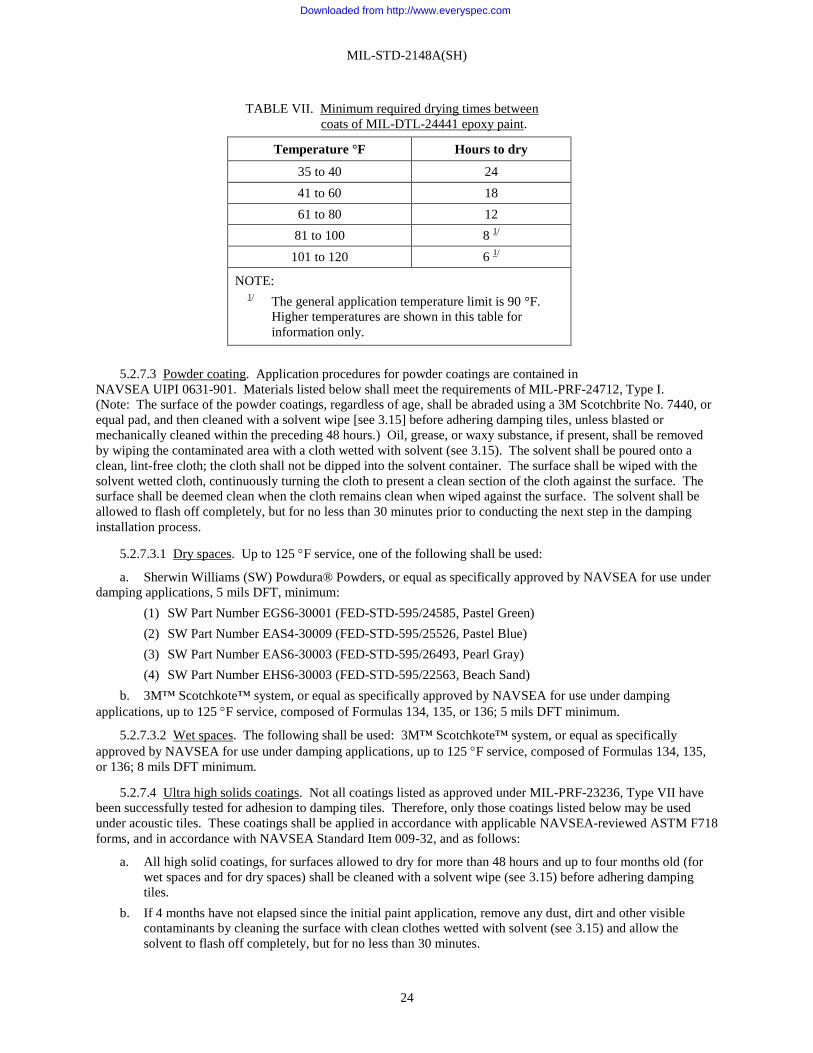
MIL-STD-2148A(SH)
24
TABLE VII. Minimum required drying times between
coats of MIL-DTL-24441 epoxy paint.
Temperature °F Hours to dry
35 to 40 24
41 to 60 18
61 to 80 12
81 to 100 8 1/
101 to 120 6 1/
NOTE: 1/
The general application temperature limit is 90 °F.
Higher temperatures are shown in this table for
information only.
5.2.7.3 Powder coating. Application procedures for powder coatings are contained in
NAVSEA UIPI 0631-901. Materials listed below shall meet the requirements of MIL-PRF-24712, Type I.
(Note: The surface of the powder coatings, regardless of age, shall be abraded using a 3M Scotchbrite No. 7440, or
equal pad, and then cleaned with a solvent wipe [see 3.15] before adhering damping tiles, unless blasted or
mechanically cleaned within the preceding 48 hours.) Oil, grease, or waxy substance, if present, shall be removed
by wiping the contaminated area with a cloth wetted with solvent (see 3.15). The solvent shall be poured onto a
clean, lint-free cloth; the cloth shall not be dipped into the solvent container. The surface shall be wiped with the
solvent wetted cloth, continuously turning the cloth to present a clean section of the cloth against the surface. The
surface shall be deemed clean when the cloth remains clean when wiped against the surface. The solvent shall be
allowed to flash off completely, but for no less than 30 minutes prior to conducting the next step in the damping
installation process.
5.2.7.3.1 Dry spaces. Up to 125 F service, one of the following shall be used:
a. Sherwin Williams (SW) Powdura® Powders, or equal as specifically approved by NAVSEA for use under
damping applications, 5 mils DFT, minimum:
(1) SW Part Number EGS6-30001 (FED-STD-595/24585, Pastel Green)
(2) SW Part Number EAS4-30009 (FED-STD-595/25526, Pastel Blue)
(3) SW Part Number EAS6-30003 (FED-STD-595/26493, Pearl Gray)
(4) SW Part Number EHS6-30003 (FED-STD-595/22563, Beach Sand)
b. 3M™ Scotchkote™ system, or equal as specifically approved by NAVSEA for use under damping
applications, up to 125 F service, composed of Formulas 134, 135, or 136; 5 mils DFT minimum.
5.2.7.3.2 Wet spaces. The following shall be used: 3M™ Scotchkote™ system, or equal as specifically
approved by NAVSEA for use under damping applications, up to 125 F service, composed of Formulas 134, 135,
or 136; 8 mils DFT minimum.
5.2.7.4 Ultra high solids coatings. Not all coatings listed as approved under MIL-PRF-23236, Type VII have
been successfully tested for adhesion to damping tiles. Therefore, only those coatings listed below may be used
under acoustic tiles. These coatings shall be applied in accordance with applicable NAVSEA-reviewed ASTM F718
forms, and in accordance with NAVSEA Standard Item 009-32, and as follows:
a. All high solid coatings, for surfaces allowed to dry for more than 48 hours and up to four months old (for
wet spaces and for dry spaces) shall be cleaned with a solvent wipe (see 3.15) before adhering damping
tiles.
b. If 4 months have not elapsed since the initial paint application, remove any dust, dirt and other visible
contaminants by cleaning the surface with clean clothes wetted with solvent (see 3.15) and allow the
solvent to flash off completely, but for no less than 30 minutes.
Downloaded from http://www.everyspec.com

Downloaded from http://www.everyspec.com

MIL-STD-2148A(SH)
26
5.2.7.4.2 Wet spaces. One of the following coatings shall be applied to wet spaces:
a. Sherwin Williams Dura-Plate Coating in accordance with MIL-PRF-23236, Type VII, or equal as
specifically approved by NAVSEA for use under damping applications, two coats (Ultra High Solids Primer, 8 to
10mils DFT; topcoat, Ultra High Solids topcoat, 12 to 20 mils DFT), total 20 to 30 mils DFT. A stripe coat Ultra
High Solids topcoat, 10 to 15 mils DFT, shall then be applied if the coating DFT is less than 20 to 30 mils thick or a
single coat, 20 to 30 DFT mils thick may be applied in one operation. This shall be followed by a brush coat, 10 to
15 mils DFT thick if the single coat is less than 20 to 30 mils DFT thick; or
b. Sherwin Williams Fast Clad, in accordance with MIL-PRF-23236, Type VII, or equal as specifically
approved by NAVSEA for use under damping applications, two coats (Blue primer, 8 to 10 mils DFT and White or
Green topcoat, 12 to 20 mils DFT), total 20 to 30 mils DFT in all areas. A White or contrasting light color stripe
coat, 10 to 15 mils DFT, shall then be applied if the coating is less than 20 to 30 mils thick. Or one coat Blue
primer, 20 to 30 mils DFT, applied in one operation. This shall be followed by a brush coat, 10 to 15 mils DFT
thick if the single coat is less than 20 to 30 mils DFT thick. (Note: The pot life for Sherwin Williams Fast Clad is
advertised as 7 minutes at 77 °F. The use of plural component spray equipment is required; applicators need to be
conscious of the potential for this material to set-up in the spray line.)
5.2.7.5 Application of coatings.
5.2.7.5.1 Dry spaces. Paint that is allowed to dry for more than 48 hours shall be cleaned by wiping with a
clean cloth wetted with solvent (see 3.15), prior to application of the next coat. When painting of the stud threads is
not desirable, the studs shall, at a minimum, be painted up to the bottom thread. The threaded portion of the studs
shall be taped or covered with a short length of tubing or protective cap in order to protect the threads during
subsequent cleaning operations, surface preparation, and tile installation. Flexible plastic electrical sleeving in
accordance with MIL-I-631 may be used. If more than 1 year has elapsed between painting and installation of the
tile, the paint shall be sweep blasted and an additional cover coat of paint applied for all coatings except Ultra High
Solids coatings (see 5.2.7.4 for Ultra High Solids coatings requirements). If more than 4 months but less than 1 year
has elapsed before tile application, the painted surfaces shall be hand or power sanded for all coatings, or sweep
blasted (except Ultra High Solids coatings) before tile application. Oil, grease, or other contamination, if present,
shall be removed from the painted surfaces, regardless of age, before tile application. Oil, grease, or waxy
substance, if present, shall be removed by wiping the contaminated area with a cloth wetted with solvent (see 3.15).
The solvent shall be poured onto a clean, lint-free cloth; the cloth shall not be dipped into the solvent container. The
surface shall be wiped with the solvent wetted cloth, continuously turning the cloth to present a clean section of the
cloth against the surface. The surface shall be deemed clean when the cloth remains clean when wiped against the
surface. The solvent shall be allowed to flash off completely, but for no less than 30 minutes prior to conducting the
next step in the damping installation process. Where abrasive blasting is impractical due to proximity of installed
machinery or equipment, the surfaces may be mechanically cleaned. The surface profile shall be 2 mils minimum.
Any oil, grease, or other contamination on the painted surfaces shall be removed by wiping with a cloth wetted with
solvent (see 3.15).
Downloaded from http://www.everyspec.com

MIL-STD-2148A(SH)
27
5.2.7.5.2 Wet spaces. Paint that is allowed to dry for more than 48 hours shall be cleaned by wiping with a
clean cloth wetted with solvent (see 3.15), prior to application of the next coat. If painting the threads of the studs is
not desired, as a minimum, the studs shall be painted up to the bottom thread. The threaded portion of the studs
shall be taped or covered with a short length of tubing or protective cap in order to protect the threads during
subsequent cleaning operations, surface preparation, and tile installation. Flexible plastic electrical sleeving in
accordance with MIL-I-631 may be used. Before adhering damping tiles over Ultra High Solids coatings, for
surfaces allowed to dry for more than 48 hours and up to four months old, the surface of the Ultra High Solids
coatings shall be cleaned with a solvent wipe (see 3.15). Oil, grease, or waxy substance, if present, shall be removed
by wiping the contaminated area with a cloth wetted with solvent (see 3.15). The solvent shall be poured onto a
clean, lint-free cloth; the cloth shall not be dipped into the solvent container. The surface shall be wiped with the
solvent wetted cloth, continuously turning the cloth to present a clean section of the cloth against the surface. The
surface shall be deemed clean when the cloth remains clean when wiped against the surface. The solvent shall be
allowed to flash off completely, but for no less than 30 minutes prior to conducting the next step in the damping
installation process. When more than 4 months have elapsed between application of any approved paint system,
except for Ultra High Solids coatings, and tile installation, the paint shall be sweep blasted and an additional mist
coat of paint shall be applied (see 5.2.7.4 for Ultra High Solids coatings requirements). Where sweep blasting is
impractical for a small area or because of possible damage to adjacent installations or equipment, the area may be
hand- (60- to 120-grit paper) or power-sanded prior to the mist coat. The surface profile shall be 2 mils minimum.
If an individual area to be hand- or power-sanded exceeds 12 square feet or if the accumulation of areas 12 square
feet or smaller exceeds 25 percent of the total surface to be damped in the given ballast or trim tank, the area(s) shall
be inspected to ensure loose paint, other contaminants, and surface gloss have been properly removed.
5.2.7.5.3 Gear cases and structures that operate at temperatures of 80 to 155 °F. After the steel surfaces have
been prepared as in 5.2.3.1, the clean metal surfaces shall then be coated with a paint type as specified in 5.2.7.2.
5.2.7.5.4 Non-steel surfaces. The blasted non-steel, metal surfaces shall be coated with one coat of yellow
primer in accordance with Formula 158, MIL-DTL-24441/37, and allowed to dry in accordance with table VII. The
painted surfaces shall be scrubbed with a clean cloth wetted with solvent (see 3.15), and sanded by hand using
60-grit emery cloth. Dust shall be removed with a clean brush. Aluminum alloy exposed to seawater, oils, or
hydraulic fluid shall be given additional coats of Formula 151, MIL-DTL-24441/30, and Formula 152,
MIL-DTL-24441/31, to a total dry paint film thickness of at least 8 mils. Aluminum alloys in dry spaces shall be
given one additional coat of Formula 151, MIL-DTL-24441/30. Each coat shall be allowed a minimum drying time
in accordance with table VII prior to application of the next coat. The paint shall be given additional drying time if
it can be indented with a fingernail. When more than 4 months has elapsed between painting and installation of tile,
the paint shall be sweep blasted or hand sanded with 60- to 120-grit paper and an additional cover coat of paint shall
be applied.
5.2.8 Amine bloom. All protective coatings, except for powder coatings, shall be examined for amine bloom.
5.2.8.1 Examination for amine bloom. Amine bloom is a waxy film that may come to the surface of epoxy
paints during the curing process. This is the result of unreacted amine-type curing agents migrating to the surface of
the cured coating. These excess amine-type agents may be present in both MIL-DTL-24441 and Ultra High Solids
coatings. Powder coatings do not produce amine bloom and do not have to be tested. Amine bloom is generally
promoted by conditions of low temperature or high humidity, or both, existing at the time the paint or coating is
applied. Existence of amine bloom is more critical in wet areas. The examination for amine bloom shall be in
accordance with 5.2.8.2.
5.2.8.2 Amine bloom examination and removal procedure. The examination and removal procedures for amine
bloom shall be as follows:
a. The presence of amine bloom can be detected by either appearance or feel of the surface in question.
b. Examination for amine bloom shall be conducted by an experienced person whenever additional coats of
paint or adhesive are to be applied over an epoxy coating.
c. Amine bloom shall be removed by scrubbing with a 50/50 blend, by volume, of fresh water and ethyl
alcohol in accordance with A-A-53880 or a 70/30 fresh water/isopropyl alcohol solution. Denatured alcohol shall
not be used. Following initial cleaning, a retest for amine bloom shall be conducted and cleaning shall be continued
until amine bloom test is no longer positive.
Downloaded from http://www.everyspec.com

MIL-STD-2148A(SH)
28
5.2.8.3 Referee test procedure for detection of amine bloom. The presence of amine bloom is generally
determined by visual and tactile examination. However, if amine bloom is suspected, but cannot be confirmed by
these examinations, the following test can be conducted to establish if it is present:
a. Two or more filter papers shall be prepared for testing, each approximately 1 square inch in size. The filter
paper should be clean and dry.
b. Examination for amine bloom shall be conducted by a person experienced in the referee test procedure
whenever additional coats of paint or adhesive are to be applied over an epoxy coating.
c. A clean pair of tongs shall be used to place the filter papers in a saturated solution of sodium-1,
2-naphthoquinone-4-sulfonate in a mixture of 50 percent ethanol and 50 percent distilled water, 0.214 ounces/gallon
or 1,600 parts per million at 77 °F. Applicable local safety precautions shall be observed when using these
materials.
d. The tongs shall be used to place one doused filter paper on the painted surface in question. The second
filter paper shall be allowed to dry without touching any possible source of contamination.
e. The filter paper shall be allowed to remain on the surface for 1 minute so that the reactions have time to
complete.
f. The underside of the filter paper shall be visually inspected. A positive response is signified by a purple
stain on the filter paper. Use the dry uncontaminated filter paper as a color reference. If a positive amine bloom test
occurs, clean and retest as in 5.2.8.2.c.
g. Any stain on the paint should be sanded off with 80-grit paper and then solvent washed with 50/50 water and
ethyl alcohol solution , or a 70/30 fresh water/isopropyl alcohol solution, prior to subsequent bonding procedures.
Denatured alcohol shall not be used.
5.2.9 Adhesive. Adhesive for vibration damping tiles shall be in accordance with MIL-A-24456, or for
SSN 688 and SSBN 726 Classes only, 3M™ VHB™ 4926 pressure-sensitive tape, or equal as approved by
NAVSEA for use under damping applications, may be used in lieu of epoxy adhesive only for Type II, Class 1, 2,
and Type V tiles when installed on MIL-DTL-24441 paint. Note: Before adhering damping tiles with
3M™ VHB™ 4926 pressure-sensitive tape, or equal over powder coatings, the surface of the coating shall be
abraded using a 3M Scotchbrite No. 7440, or equal pad, and then cleaned with solvent (see 3.15). Epoxy adhesive
and pressure-sensitive tape shall be stored in accordance with manufacturer’s directions. The epoxy adhesive has a
shelf life of 6 months if stored in cartridge form, or 2 years if in other packaging. Expired epoxy adhesive packages
can be re-certified as acceptable for a 6-month shelf life extension if successfully retested to all lot conformance
tests less the pot life test. 3M™ VHB™ 4926 pressure-sensitive tape has a shelf life of 24 months from date of
manufacture when stored at 40 to 100 °F and 0-95 percent relative humidity. The optimum storage conditions are
72 °F and 50 percent relative humidity.
5.2.9.1 Environmental requirements. In order to achieve the desired damping performance, a complete
adhesive bond is required between the coated steel surface and the damping material. This requires that each layer
of the bond (all paint coats and the adhesive) be fully cured. Epoxy materials or adhesive tape, in general, cure
through a chemical reaction. To achieve complete cure, the initial mixing or application of the components shall be
within the following temperature conditions, which shall be maintained during the material installation:
a. During the application of MIL-A-24456 adhesives, the temperature of the work area shall be maintained
between 35 and 95 °F. Epoxy compounds will not cure correctly at temperatures below 35 °F. When the work area
temperature is below 50 °F the MIL-A-24456 adhesive components shall be preheated to 70 °F mixed at 70 °F or
greater (not to exceed 95 °F) and then carried to the work site. This is essential to ensure proper curing of the
adhesive. Normally, MIL-A-24456 adhesive will harden after 24 hours at 72 °F. It may take as long as 15 days to
harden at 35 °F. The higher the work area temperature, the faster the cure will be.
b. For adhesive tape, the surface temperature of the structure to which the tile is being applied shall be a
minimum of 60 °F from tile installation through cure of the tape. If the surface temperature of the structure is below
60 °F it shall be preheated to at least 60 °F. The tape and tile assembly shall be maintained at a minimum of 60 °F
and, when needed, carried directly to the worksite from the 60 °F environment.
Downloaded from http://www.everyspec.com

MIL-STD-2148A(SH)
29
5.2.9.2 Preparation of MIL-A-24456 epoxy adhesive. Adhesive conforming to MIL-A-24456 shall be used to
bond the tiles to the structure to be damped. This adhesive is a two-component epoxy system. The components
shall be blended together, in the ratio recommended by the manufacturer, just before application. Adhesive
components shall be thoroughly blended to ensure that the adhesive will be uniformly hard when it sets up.
Components usually are furnished in two markedly dissimilar colors, so that the blended adhesive admixture will be
distinctly different in color with respect to either of the components. Properly mixed adhesive is uniform in color
and shall show no evidence of any color streaks. Adhesive conforming to MIL-A-24456 may be pre-packaged in
barrier kits and mixed mechanically with automatic mixing equipment designed to be compatible with the barrier
kits, or using manually operated cartridges and static mixing tubes. A visual inspection of the structure shall be
conducted before applying adhesive in accordance with standard practices to ensure surface cleanliness prior to
further surface preparation. Any oil, grease, or waxy contamination present on the steel or on a painted surface
before tile application shall be removed with a clean cloth wetted with solvent (see 3.15).
5.2.9.2.1 Cleaning. Epoxy adhesives conforming to MIL-A-24456 are difficult to remove once they harden,
Excess adhesive shall be removed from mixing and application equipment and the equipment cleaned using hot
water and detergent in accordance with MIL-D-16791, Type I, or equal, before the adhesive has begun to set.
5.2.9.3 3M™ VHB™ tape, or equal as approved by NAVSEA. For SSN 688 and SSBN 726 Classes only, the
following procedure may be substituted in lieu of the epoxy adhesive application procedure listed for Type II,
Class 1 and 2 only, and Type V, in 5.3, 5.4, 5.6, and 5.7.
5.2.9.3.1 Adhesive tape application to free-layer or restrained layer tiles.
a. Cleaning procedure: All components (3M™ VHB™ 4926 pressure-sensitive tape, or equal as approved by
NAVSEA for use under damping tile, and vibration damping tile) shall be at a minimum temperature of 50 °F prior
to bonding the tape to the tile. The side of the damping tile on which the adhesive tape is to be applied shall be
scraped to create a smooth surface. If needed, all blisters or irregularities shall be removed. Care shall be taken to
avoid gouging the tile while scraping. Both sides of the damping tile on which each tape adhesive is to be applied
shall be abraded with 60- to 80-grit paper to create a smooth surface. The surface of the tile on which the adhesive
tape is to be applied shall be cleaned. Oil, grease, or waxy substance, if present, shall be removed by wiping the
contaminated area solvent (see 3.15). The solvent shall be poured onto a clean, lint-free cloth; the cloth shall not be
dipped into the solvent container. The surface shall be wiped with the solvent wetted cloth, continuously turning the
cloth to present a clean section of the cloth against the surface. The surface shall be deemed clean when the cloth
remains clean when wiped against the surface. The solvent shall be allowed to flash off completely, but for no less
than 30 minutes prior to conducting the next step in the damping installation process. The surface shall be allowed
to dry completely before the tape is installed.
b. Apply 3M™ VHB™ 4926 pressure-sensitive tape to tile: When bonding the 3M™ VHB™ 4926
pressure-sensitive tape, or equal as approved by NAVSEA for use under damping tile, to the tile, only one side of
the tape shall be exposed. Backing paper shall remain on the other side until the tile is installed on a structure. The
adhesive tape shall be applied to the tile. The tape shall completely cover the surface of the tile. The edges of the
tape shall be aligned with the edges of the tile. Special care shall be exercised to ensure that the tape is smooth, flat,
and extends completely to the edges and corners of the tile.
c. Cut holes in 3M™ VHB™ 4926 pressure-sensitive tape, or equal as approved by NAVSEA for use under
damping applications, for restraining layer: For restrained tiles, the stud through-holes shall be pre-cut in the tile,
and the tape applied over those holes initially. After it is applied, the tape can be removed from the hole by carefully
cutting around the hole edge. The edge of the tape around the through-holes shall not be lifted off of the tile or
otherwise disturbed during the cutting process. If holes are pre-cut in the tape, then care shall be exercised to ensure
the tape is not contaminated during the cutting process, and that holes in the tape and tile are aligned.
d. Roll the 3M™ VHB™ 4926 pressure-sensitive tape, or equal as approved by NAVSEA for use under
damping applications: A downward force using a steel hand roller shall be applied over the entire surface of the
tape. The steel hand roller shall be rolled on the side of the tape with backing paper still on it. The edges and
corners of the tape shall be examined to ensure they are bonded to the tile. The tile shall be kept in a clean, dry area
for 72 hours at a minimum temperature of 50 °F to allow the tape to cure.
Downloaded from http://www.everyspec.com

MIL-STD-2148A(SH)
30
5.2.9.3.2 Adhesive taped free-layer or restrained layer tile application to structure.
a. Environmental controls and surface preparation: The surface temperature of the structure to which the tile
is being applied shall be a minimum of 50 °F from tile installation through cure of the 3M™ VHB™ 4926
pressure-sensitive tape, or equal as approved by NAVSEA for use under damping applications. If the surface
temperature of the structure is below 50 °F it shall be preheated to at least 50 °F. The tape and tile assembly shall be
maintained at a minimum of 50 °F and, when needed, carried directly to the worksite from the 50 °F environment.
A visual inspection n in accordance with standard practices shall be conducted to ensure surface cleanliness prior to
further surface preparation. Oil, grease, or waxy substance, if present, shall be removed from the surface of the paint
to which tiles are to be applied by wiping the contaminated area with a cloth wetted with solvent (see 3.15). The
solvent shall be poured onto a clean, lint-free cloth; the cloth shall not be dipped into the solvent container. The
surface shall be wiped with the solvent wetted cloth, continuously turning the cloth to present a clean section of the
cloth against the surface. The surface shall be deemed clean when the cloth remains clean when wiped against the
surface. The solvent shall be allowed to flash off completely, but for no less than 30 minutes prior to conducting the
next step in the damping installation process. If the substrate is coated with a Ultra High Solids coating, avoid
sanding the painted substrate if possible. Testing has shown that the 3M™ VHB™ 4926 pressure-sensitive tape, or
equal, as approved by NAVSEA for use under damping applications, adheres better to a smooth Ultra High Solids
painted surface versus a sanded surface. If there are small irregularities other than the typical orange peel effect in
the Ultra High Solids painted surface, smooth these out with a 3M Scotchbrite No. 7440, or equal. If the Ultra High
Solids painted surface has large drips or runs, sand these down with 60- to 80-grit paper, then smooth out the sanded
surface with a 3M Scotchbrite No. 7440, or equal. If the surface is coated with MIL-P-24441 Type III or Type IV,
the surface of the paint shall be roughened and any runs, drips, or sags smoothed out with 60- to 80-grit paper. The
surface shall be sanded to approximately 75 percent degloss. If hand sanded, a cross-hatch pattern is recommended
to ensure good adhesion. The prepared structure shall be cleaned again with a clean, lint-free cloth wetted with
solvent (see 3.15) just prior to installation of the tile, as noted above.
b. Apply taped tile: The tile shall be positioned and pressed into place utilizing only light hand pressure. If
the tile is misplaced, the tile shall be carefully removed and it shall be verified that there is no damage to the tape
before the tile is re-positioned. Damage is defined as 5 percent or greater damage to either the upper surface or the
perimeter of the tile or the adhesive bond. If any of the area of the 3M™ VHB™ 4926 pressure-sensitive tape, or
equal as approved by NAVSEA for use under damping applications, on a single tile is damaged during
repositioning, all the tape on that tile shall be replaced with new tape that is installed on the tile and cured in
accordance with the procedures above. The entire surface of the tape shall be flat and in contact with the structure.
When the tile is aligned in its final position, a steel hand roller shall be used to apply downward force over the entire
surface of the tile. As an alternative, use a 4–inch, two-handed Rockler Power Roller, or equal, to apply downward
force on the tile over the entire surface of the tile. (Note: Any tool other than a steel hand roller shall not be used
because it has been found to be the most effective at producing a strong bond when compared to other tools, such as
a mallet.) If necessary, additional shoring shall be used to ensure the tile lies flat during the entire curing process.
The installed tile assembly shall be allowed to cure for a minimum of 72 hours at 60 °F, during which time the tile
shall remain dry. The structure to which the tile was applied and the tile assembly shall be maintained at a minimum
of 50 °F throughout the cure.
5.2.9.3.3 Adhesive tape application to constrained layer tiles.
a. Initial cleaning procedure: All components (3M™ VHB™ 4926 pressure-sensitive tape, or equal as
approved by NAVSEA for use under damping applications ,vibration damping tile, and steel constraining layer)
shall be at a minimum temperature of 50 °F prior to bonding the tape to the tile and constraining layer. Both sides of
the damping tile shall be scraped to create smooth surfaces. If needed, any blisters or irregularities shall be
removed. Care shall be taken to avoid gouging the tile while scraping.
Downloaded from http://www.everyspec.com
MIL-STD-2148A(SH)
31
b. Solvent cleaning: The surface of the steel constraining layer on which the 3M™ VHB™ 4926
pressure-sensitive tape, or equal as approved by NAVSEA for use under damping tile, is to be applied and one side
of the damping tile shall be cleaned with solvent (see 3.15) using a clean, lint-free cloth. Oil, grease, or waxy
substance, if present, shall be removed by wiping the contaminated area with a cloth wetted with solvent (see 3.15).
The solvent shall be poured onto a clean, lint-free cloth; the cloth shall not be dipped into the solvent container. The
surface shall be wiped with the solvent wetted cloth, continuously turning the cloth to present a clean section of the
cloth against the surface. The surface shall be deemed clean when the cloth remains clean when wiped against the
surface. The solvent shall be allowed to flash off completely, but for no less than 30 minutes prior to conducting the
next step in the damping installation process. The surface shall be allowed to dry completely before installing the
adhesive tape. Care shall be exercised to avoid contamination of the cleaned surfaces during drying. The surface of
the constraining layer paint shall be roughened and any runs, drips, sags smoothed out with 60- to 80-grit paper.
The surface shall be sanded to approximately 75 percent degloss. If hand sanded, a cross-hatch pattern is
recommended to ensure good adhesion. Both sides of the damping tile on which each tape adhesive is to be applied
shall be abraded with 60- to 80-grit paper to create a smooth surface.
c. Solvent cleaning after deglossing: The sanded constraining layer and the damping tile shall be cleaned
again with solvent (see 3.15) using a clean, lint-free cloth just prior to installation of the adhesive tape. Oil, grease,
or waxy substance, if present, shall be removed by wiping the contaminated area with a cloth wetted with solvent
(see 3.15). The solvent shall be poured onto a clean, lint-free cloth; the cloth shall not be dipped into the solvent
container. The surface shall be wiped with the solvent wetted cloth, continuously turning the cloth to present a clean
section of the cloth against the surface. The surface shall be deemed clean when the cloth remains clean when
wiped against the surface. The solvent shall be allowed to flash off completely, but for no less than 30 minutes prior
to conducting the next step in the damping installation process. It shall be ensured that the solvent has completely
evaporated before the tape is installed.
d. Apply 3M™ VHB™ 4926 pressure-sensitive tape, or equal as approved by NAVSEA for use under
damping tile, to constraining layer: When bonding the adhesive tape to the constraining layer or tile, only one side
of the tape shall be exposed. Backing paper shall remain on the other side until the tile is installed on the
constraining layer or on a structure. The adhesive tape shall be applied to the cleaned side of the steel constraining
layer. The tape shall completely cover the surface of the constraining layer. The edges of the tape shall align with
the edges of the steel. Special care shall be exercised to ensure that the tape is smooth, flat, and extends completely
to the edges and corners of the constraining layer.
e. Apply tile to constraining layer: Care shall be taken to align the cleaned side of the damping tile over the
exposed 3M™ VHB™ 4926 pressure-sensitive tape, or equal as approved by NAVSEA for use under damping tile,
on the constraining layer and to press the tile into place utilizing only light hand pressure. The edges of the tile
should be aligned with the edges of the constraining layer and the through-holes shall be aligned. The entire surface
of the tile shall be in contact with the tape on the constraining layer. If the tile is misplaced, the tile shall be
carefully removed and it shall be verified that there is no damage to the tape before the tile is re-positioned. If any
of the area of the adhesive tape on a single constraining layer is damaged during repositioning, all the tape shall be
replaced with new tape. Damage is defined as 5 percent or greater damage to either the upper surface or the
perimeter of the tile or the adhesive bond. A steel hand roller shall be used to apply downward force over the entire
surface of the tile. As an alternative, use a 4inch, two-handed Rockler Power Roller, or equal, to apply downward
force on the tile over the entire surface of the tile. Special care shall be exercised to ensure that the entire bottom
surface of the tile is bonded to the constraining layer.
f. Clean tile: The side of the tile with no adhesive tape shall be cleaned with solvent (see 3.15) using a clean,
lint-free cloth. Ensure that no solvent is allowed to drip down onto, or otherwise contaminate, the edge of the tape
between the tile and the constraining layer. Oil, grease, or waxy substance, if present, shall be removed by wiping
the contaminated area with a cloth wetted with solvent (see 3.15). The solvent shall be poured onto a clean, lint-free
cloth; the cloth shall not be dipped into the solvent container. The surface shall be wiped with the solvent wetted
cloth, continuously turning the cloth to present a clean section of the cloth against the surface. The surface shall be
deemed clean when the cloth remains clean when wiped against the surface. The solvent shall be allowed to flash
off completely, but for no less than 30 minutes prior to conducting the next step in the damping installation process.
The surface shall be allowed to dry completely before the tape is installed. Care shall be exercised to avoid
contamination of the cleaned surface during drying.
Downloaded from http://www.everyspec.com

MIL-STD-2148A(SH)
32
g. Apply 3M™ VHB™ 4926 pressure-sensitive tape, or equal as approved by NAVSEA for use under
damping tile, to tile: The adhesive tape shall be applied to the cleaned side of the tile. The tape shall completely
cover the surface of the tile. The edges of the tape shall be aligned with the edges of the tile. Special care shall be
exercised to ensure that the tape is smooth, flat, and extends completely to the edges and corners of the tile. It is
recommended that the tape be applied over the through-holes initially. Care can then be exercised to remove the
tape from the hole area by cutting around the hole edge. If holes are pre-cut in the tape, then care shall be exercised
to ensure the tape is not contaminated during the cutting process. A steel hand roller shall be used to apply
downward force on the tape over the entire surface of the tile. As an alternative, use a 4–inch, two-handed Rockler
Power Roller, or equal, to apply downward force on the tile over the entire surface of the tile. It shall be ensured
that the edges and corners of the tape are bonded to the tile. The constrained tile assembly shall be kept in a clean,
dry area and the tape cured for 72 hours at a minimum temperature of 50 °F.
5.2.9.3.4 Adhesive taped constrained layer tile application to structure.
a. Environmental requirements: The surface temperature of the structure to which the constrained tile
assembly is being applied shall be a minimum of 50 °F from tile installation through cure of the tape. If the surface
temperature of the structure is below 50 °F, it shall be preheated to at least 50 °F. The constrained tile assembly
shall be maintained at a minimum of 50 °F and, when needed, carried directly to the worksite from the 50 °F
environment.
b. Prepare coated surface: The surface of the paint to which the tile assemblies are to be applied shall be
cleaned with solvent (see 3.15), using a clean, lint-free cloth before the surface is sanded. Oil, grease, or waxy
substance, if present, shall be removed by wiping the contaminated area with a cloth wetted with solvent (see 3.15).
The solvent shall be poured onto a clean, lint-free cloth; the cloth shall not be dipped into the solvent container. The
surface shall be wiped with the solvent wetted cloth, continuously turning the cloth to present a clean section of the
cloth against the surface. The surface shall be deemed clean when the cloth remains clean when wiped against the
surface. The solvent shall be allowed to flash off completely, but for no less than 30 minutes prior to conducting the
next step in the damping installation process. It shall be ensured that the solvent has completely evaporated before
the constrained tile assembly is installed. If the substrate is coated with a Ultra High Solids coating, avoid sanding
the painted substrate if possible. Testing has shown that the 3M™ VHB™ 4926 pressure-sensitive tape, or equal, as
approved by NAVSEA for use under damping tile, adheres better to a smooth Ultra High Solids painted surface
versus a sanded surface. If there are small irregularities other than the typical orange peel effect in the Ultra High
Solids painted surface, smooth these out with a 3M Scotchbrite No. 7440, or equal. If the Ultra High Solids painted
surface has large drips or runs, sand these down with 60 to 80-grit paper, then smooth out the sanded surface with a
3M Scotchbrite No. 7440, or equal. If the surface is coated with MIL-P-24441 Type III or Type IV paint, the
surface of the paint shall be roughened and any runs, drips, or sags smoothed out with 60- to 80-grit paper. The
surface shall be sanded to approximately 75 percent degloss. If hand sanded, a cross-hatch pattern is recommended
to ensure good adhesion.
c. Clean coated surface: The prepared structure shall be cleaned again with solvent (see 3.15), using a clean,
lint-free cloth just prior to installation of the constrained tile assembly. Oil, grease, or waxy substance, if present,
shall be removed by wiping the contaminated area with a cloth wetted with solvent (see 3.15). The solvent shall be
poured onto a clean, lint-free cloth; the cloth shall not be dipped into the solvent container. The surface shall be
wiped with the solvent wetted cloth, continuously turning the cloth to present a clean section of the cloth against the
surface. The surface shall be deemed clean when the cloth remains clean when wiped against the surface. The
solvent shall be allowed to flash off completely, but for no less than 30 minutes prior to conducting the next step in
the damping installation process. It shall be ensured that the solvent has completely evaporated before the
constrained tile is installed.
Downloaded from http://www.everyspec.com

MIL-STD-2148A(SH)
33
d. Apply tile assembly: The tile shall be positioned and pressed into place utilizing only light hand pressure.
If the tile is misplaced, the tile shall be carefully removed and it shall be verified that there is no damage to the tape
before the tile is re-positioned. Damage is defined as 5 percent or greater damage to either the upper surface or the
perimeter of the tile or the adhesive bond. If any of the area of the adhesive tape on a single tile is damaged during
repositioning, all the tape on that tile shall be replaced with new tape that is installed on the tile and cured in
accordance with the procedures above. The entire surface of the tape shall be flat and in contact with the structure.
When the tile is aligned in its final position, a steel hand roller shall be used to apply downward force on the tile
over the entire surface of the tile. As an alternative, use a 4–inch, two-handed Rockler Power Roller, or equal, to
apply downward force on the tile over the entire surface of the tile. (Note: Any tool other than a steel hand roller
shall not be used because it has been found to be the most effective at producing a strong bond when compared to
other tools, such as a mallet.) Care shall be exercised to ensure downward force is applied to the tile assembly
edges, corners and around the edges of the stud holes to ensure good adhesion. If necessary, additional shoring shall
be used to ensure the tile lies flat during the entire curing process.
e. Attach fasteners and cure: Constraining washers and nuts, or washer nut assemblies, may be applied to the
constrained tile assembly to secure it while the adhesive cures. Neither the separate washer nor the washer face of
the washer nut assembly, if used, shall be bonded to the damping tile. However, the nuts shall not be tightened to
the point where the tile assembly deforms because this will cause the adhesive to debond from the structure. If
necessary, the nuts shall be retightened to the minimum required torque levels after the adhesive cures. Cure for a
minimum of 72 hours at 50 °F during which time the tile shall remain dry. The structure to which the tile was
applied and the tile assembly shall be maintained at a minimum of 50 °F throughout the cure.
f. Inspect cured assembly: Each constrained tile assembly shall be inspected following the adhesive cure and
any final nut tightening. It is critical that the entire surface of the assembly be fully bonded to the structure. If
necessary, additional shoring shall be used to ensure the tile lies flat during the entire curing process. If the edges or
corners of the constrained tile assembly have lifted off the structure at all, or if the middle is bowed up or it appears
that the entire surface is not bonded to the structure, then all such constrained tile assemblies shall be removed from
the structure and inspected. If the tile debonded because it cannot conform to the structure, because of structure
curvature, then the tile assembly may be reinstalled with epoxy adhesive in accordance with the procedures in 5.2.9
once all the old tape has been completely removed from the tile and the structure. Otherwise, the tile may be
re-installed with new adhesive tape in accordance with the procedures above.
5.2.10 Corrosion protection, habitability, and antifouling paint application.
5.2.10.1 Corrosion protection and habitability area paints. Tiles installed inside submarine pressure hulls and
in surface ship living or working areas shall be painted with a thin, wet coat of Formula 150, MIL-DTL-24441/29,
followed by whatever paint normally is applied in the particular area. As an alternative, Formula 152 may be used
as the topcoat to match undamped interior finish paint, and may be tinted to match FED-STD-595 color standards
for pastel green, pastel blue, beach sand and pearl gray.
5.2.10.2 Heavy plate damping. Type II constrained layer, and Type V, Class 1 installations, including exposed
ends of studs and washers, that are likely to be in contact with oil or sea water shall be coated with a paint type as
specified in 5.2.7. In all other areas external to submarine pressure hulls, or in wet spaces of surface ships, Type II
and Type V, Class 1 damping treatment shall be given a thin, wet coat of Formula 150, MIL-DTL-24441/29, primer
followed by coating with the paint specified for the area.
5.2.10.3 Type III damping systems on surface ships. Before protective paint coatings are applied to the
exposed surfaces of the Type III damping tiles, the tiles shall be hand washed with an aqueous detergent solution
such as 1 ounce of MIL-D-16791, Type I detergent per gallon of fresh water, to remove any parting compounds or
solutions. The detergent solution shall be rinsed away with fresh water and the surfaces of the tiles dried completely
before application of any protective coating or paint. Type III damping tiles subject to immersion in oil or seawater
shall be protected with two coats of Formula 151, MIL-DTL-24441/30, Formula 152, MIL-DTL-24441/31, or
Formula 156, MIL-DTL-24441/35 paint to match the surrounding area or the color specified for the compartment.
The coating also shall be applied over tiles installed in inaccessible voids where anticorrosive coatings are required
and which are applied by the fill and drain method. Care shall be taken to ensure complete coverage of the damping
tiles.
Downloaded from http://www.everyspec.com
MIL-STD-2148A(SH)
34
5.2.10.4 Antifouling paints. Damping tiles, constraining plates and plastic restraining layers are not inherently
antifouling. In those areas where protection from fouling is required, the damping treatment shall first be painted
with a thin wet coat in accordance with Formula 150, MIL-DTL-24441/29 paint. Within 4 hours after paint
application (after the solvent has evaporated but before the paint has cured), two coats of antifouling paint,
MIL-PRF-24647, Type IV, Class 1 shall be applied. The first coat shall be applied when the epoxy paint coat is in
its final tacky stage. If the epoxy becomes too dry, good adhesion of antifouling will not be achieved. If the epoxy
has cured too hard, it shall be given a thin, continuous, mist-coat (1 to 2 mils wet film thickness) of the same epoxy
paint. This mist-coat shall be allowed to cure to a tacky stage before applying the first coat of antifouling. The
tacky stage is a function of temperature and humidity, and will vary widely with climate conditions and the type of
epoxy paint used. It is best defined as that curing (drying) stage when a fingertip pressed lightly against the film
leaves only a slight impression and none of the film sticks to the finger. Accidental overspray is acceptable. Full
paint-out of damping restraining layers is not intended. If damping tiles are painted, they shall be checked to ensure
that the paint will not bridge the gap between the tile and the restraining layer over more than 75 percent of an area.
Degradation of the performance of the tiles is possible. To repair, score the gap between the restraining layer and
the damping tile.
5.2.11 Fitting around weld beads. Damping tiles shall be close-fitted and cut to fit the surfaces between weld
beads. In order to provide for periodic inspection of welds associated with specific maintenance and surveillance
requirements, the following guidelines shall apply (see figures 6, 7, 10, and 11).
a. Tiles shall not be installed over welds.
b. Welds shall not be covered by restraining or constraining layers. Figure 10 shows a typical installation of
the damping treatment in the way of welds on plane surfaces.
c. Where periodic non-destructive tests (NDTs) of a weld are not required, damping shall be applied within
1 ±½ inch of the weld (see figures 6 and 7).
d. Where periodic NDTs of welds in accordance with MIL-STD-1689 or T9074-AD-GIB-010/1688 are
required, damping shall be installed within 2+0, -½ inches of welds (see figures 6 and 10).
e. When damping is installed around stiffeners in superstructure and fairwater areas, a ½-inch nominal
spacing shall be maintained between the damping and the stiffener overhang (see figure 11).
f. Damping in the forward trim tanks of submarines shall be installed such that a minimum of 3+½, -0-inch
spacing is maintained between the damping and welds (see 5.3.5.3 and figure 11).
g. Damping shall be installed in the forward trim tanks of submarines such that 3+½, -0 inches is maintained
between the damping and welds.
h. Tiles may be applied over welds that are on the reverse side of plating. The determination of whether or
not to apply damping over welds that are on the reverse side of the plating shall be based on the possibility of future
weld inspection complications due to installed tiles.
5.3 Installation details for types II, III, V, and VI damping tiles.
5.3.1 Installation of type II (MIL-PRF-23653, class 1, class 2, class 2.5, and class 3) damping tiles on
lightweight plate ⅛- to 11⁄16-inch thick and greater, but less than ¾-inch thick. Surface preparation and coating shall
be in accordance with 5.2.
5.3.2 Materials.
5.3.2.1 Damping tiles. Type II, Class 1, Class 2, Class 2.5, and Class 3 tiles shall be 12 by 12 inches in size,
weighing 2.8, 3.1, or 4.5 lb/ft², according to need as indicated in table II. Class 1, Class 2, Class 2.5, and Class 3
tiles shall be installed on steel plates exposed to various operating temperature ranges in accordance with table III.
Class 1 tiles that are not covered with a constraining plate and are installed in submarine ballast and trim tanks shall
be restrained with GRP or PVC septum plates.
5.3.2.2 Adhesive. See 5.2.9.
Downloaded from http://www.everyspec.com

MIL-STD-2148A(SH)
35
5.3.2.3 Restraining materials. The following materials shall be used to restrain Type II damping tiles:
a. Plastic sheet, glass-reinforced, ⅛-inch thick in accordance with MIL-P-17549, Grade 3, made with a
fire-resistant resin conforming to MIL-R-21607, or plastic sheet, PVC, ⅛-inch thick in accordance with L-P-535,
Type I, Class 3, or as an alternative, nuts and washers or CRES washer nuts as described in 5.2.6.
b. Studs, nuts, washers, and related materials in accordance with 5.2.6.
5.3.2.4 Protective materials. The following materials shall be used to protect the steel plating and damping
materials:
a. Epoxy coating system in accordance with 5.2.7 and 5.2.10.1.
b. Antifouling paint in accordance with 5.2.10.4.
5.3.2.5 Cleaning materials. The following materials shall be used to clean the steel plating and damping
materials:
a. Solvent: See 3.15.
b. Detergent, general purpose (liquid, nonionic) in accordance with MIL-D-16791, Type I.
5.3.3 Safety precautions and environmental control. See 4.5, 5.2.7.1, and 5.2.9.1.
5.3.3.1 Handling damping tiles. Tiles manufactured in accordance with MIL-PRF-23653 present no particular
health hazard and may be handled without toxic or dermatitis effects due to direct contact with the bare skin.
Graphite dust may issue from tile cutting operations, and this may be a respiratory irritant or create problems for
electric motors or capacitors in the area. Shelf life of tiles is 20 years, but some tiles are prone to sticking together at
summer temperatures if they are not properly wrapped or interwoven with Kraft (or similar) paper.
5.3.3.2 Protective measures used when handling damping materials. Adhesives, sealants, coatings, cleaning
compounds, and solvents, depending on the type being used, may present health hazards. Personnel using solvents
in closed spaces with limited ventilation shall wear air-lined masks with forced air ventilation. Specific health and
safety precautions that apply to the use of the materials are given in 4.5.
5.3.3.3 Hazardous materials and waste. Hazardous material storage and disposal of hazardous waste material
shall be in accordance with Federal, State, and local instructions.
5.3.4 Surface preparation prior to installation of damping tiles. See 5.2.1, 5.2.2, 5.2.3, 5.2.4, and 5.2.5.
5.3.4.1 Ballast and trim tank interiors.
5.3.4.1.1 Attachment of studs. Threaded 316L CRES studs of the size and length shown in table VI, shall be
welded by the automatically timed arc technique to the steel surfaces to be damped as detailed in 5.2.6. Studs for
Type II damping shall be installed on approximately 11-inch centers and spaced so that at least one stud will be
located in all tiles larger than 4 by 4 inches, and at each corner of the cover plate if cover plates covering multiple
tiles are used. If cover plates are sized to fit each tile, then only one stud, centrally located, is required.
5.3.5 Fitting of tiles.
5.3.5.1 Areas requiring a restraining layer or restraining nuts. Where a restraining layer is required for Type II
damping, a ⅛-inch thick GRP sheet in accordance with MIL-P-17549, Grade 3, or plastic sheet, PVC, ⅛ -inch thick
in accordance with L-P-535, Type I, Class 3 shall be cut to fit the area to be damped. As an alternative, separate
CRES nuts and washers or CRES washer nuts may be used in place of a restraining layer, with one stud per tile
(see 5.2.6.3.1.i). Holes, ⅞ inch in diameter, shall be made in the plastic sheet to accommodate the studs. This sheet
can be used as a template while cutting the tiles to the required shapes.
5.3.5.2 Areas not requiring a restraining layer or restraining studs (free-layer damping). For free-layer
damping, if required, a cardboard template may be cut to fit the various areas to be damped and the tiles cut to match
the template. However, tailoring usually can be accomplished as the tiles are installed.
5.3.5.3 Fitting around weld beads. See 5.2.11.
Downloaded from http://www.everyspec.com
MIL-STD-2148A(SH)
36
5.3.5.4 Drilling and punching holes, type II tiles. Holes, ⅞ inch in diameter, shall be cut, drilled, or punched in
the tiles to provide passage for the studs. Holes can be cut using a leather punch, or by drilling with a flat-end bit.
The tiles shall be kept at a temperature of 75 to 100 °F to facilitate cutting, punching, and forming operations. The
tiles usually are deformed as a result of cutting or punching operations. Surface deformation shall be corrected so
that the tile will conform to the surface to which it will be bonded. Distortion can easily be removed by trimming or
pounding with a flat-faced rubber mallet.
5.3.5.5 Preforming. Type II, Class 3 tiles to be installed on turbine gear cases may require preforming to fit the
contours of the gear case. By warming the tiles to approximately 180 °F they will become pliable and can be made
to fit irregular surfaces. Tiles so formed shall be held in position until they cool to ambient room temperature.
5.3.6 Preparation of the adhesive. See 5.2.9.
5.3.7 Installation of damping materials.
5.3.7.1 Ballast, trim tank interiors, and all other spaces that require a restraining layer system. Prior to the
application of adhesive, oil, grease, or other contaminants shall be removed from painted surfaces, regardless of age
unless blasted or mechanically cleaned within the preceding 48 hours, using a cloth wetted with solvent (see 3.15).
The tiles previously fitted shall be bonded to the painted steel structures with epoxy adhesive prepared as described
in 5.2.9. The adhesive shall be applied to one face of the tile (Type II) and to the surface to be damped, using a
dog-eared trowel of the dimensions shown on figure 12. When applying adhesive, the dog-eared trowel shall be
held at an angle of approximately 30 to 45 degrees from the normal to the structure being damped. The entire face
of the tile and the metal surfaces to be damped shall be completely covered with adhesive. The base and weld of
each stud shall be heavily coated with adhesive. It is not necessary to apply adhesive on the edges of Type II tile.
The tile shall then be pressed, adhesive side down, onto the coated metal surface, ensuring that pressure is applied
over its entire surface. Excess adhesive shall be removed immediately using a straight edged tool and may be
applied to subsequent tiles or to the surface being damped. Note: Excessive pressure around the perimeter of the
tiles, in order to get “good” adhesive extrusion, can result in gaps due to “springback” of the damping tiles. Be sure
to press the center of each tile and work toward the edges. Protective covering from stud shall be removed and the
threads shall be coated with an anti-seize compound in accordance with A-A-59313 to prevent galling of CRES nuts
and studs. It shall be permissible to install 7⁄16-inch diameter threaded CRES studs, nuts and washers, or 2-inch
diameter powder-coated integral CRES washer faced self-locking nut in accordance with figure 1, in place of the
separate nuts and washers, if desired, as needed to support temporary shoring to hold the tiles in position until the
adhesive has set. Care shall be taken in removing the shoring to prevent damage to the tile. The studs shall be cut
off where they would present a safety hazard. Also, temporary shoring may be used between center studs of
adjacent tiles. After the adhesive cures, back off the nut, the shoring shall be removed and the nut and washer shall
be restored on the permanent stud. This is particularly helpful if the surface is not perfectly cylindrical and the tiles
begin to “potato chip.” Wooden wedges, 2-inch by 4-inch and Ultra High Molecular Weight (UHMW)
Polyethylene sheets may also be used as temporary reinforcements, as needed.
Downloaded from http://www.everyspec.com

MIL-STD-2148A(SH)
37
5.3.7.1.1 Installation of the restraining layer and restraining nuts. Following removal of protective covering,
the stud shall be coated with an anti-seize compound in accordance with A-A-59313 to prevent galling of CRES
nuts and studs. The plastic restraining layer shall be positioned over the plastic tiles and the 2-inch diameter by
⅛-inch thick CRES washers and CRES locknuts, or CRES washer nuts in accordance with figure 1, installed on the
protruding studs. During installation, neither the separate washers nor the washer face of the CRES washer nut shall
be bonded to the restraining layer on the tile. The locknuts shall be tightened with a torque wrench using
40 inch-pound ±10 percent net load, or to a tolerance achieved by using a T-handle torque tool similar to Belknap
Tool No. VB75T-2, or equal. In any case, the CRES nut or the CRES washer nut shall be torqued to 40 inch-pounds
over and above the turning resistance. Turning resistance is typically an additional 20 inch-pounds, and shall be
taken into account when measuring torque. Glass fiber reinforced ULTEM™ 2300 plastic flanged nuts may have
been used as a substitute for CRES nuts and washers, for certain ships and under specific circumstances;
ULTEM™ 2300 fasteners are no longer approved for use on any ships. Also, as an alternative for all submarine
classes, a CRES nut and separate washer or a 2-inch diameter powder-coated integral CRES washer faced
self-locking nut (CRES washer nut) in accordance with figure 1, on a single stud may be used as the secondary
restraining system, in place of a restraining layer, with one stud per tile (see 5.2.6.3.1.i and 4.2.5.1). When the
single stud alternative method is used (no restraining layer used), the underside of the separate 2-inch diameter by
⅛-inch thick washers shall be coated with the epoxy adhesive so that the washer will be adhere to the face of the tile.
(3M™ VHB™ 4926 tape (see 5.2.9.3) may be substituted for the epoxy adhesive, when the 3M™ VHB™ 4926 tape
is also used to apply the tile.) The washer side of the CRES washer nuts shall not be adhered to the face of the tile.
If epoxy paint has been inadvertently applied to the threads, the locknuts will cut through the paint; however, the
nuts shall be backed off slightly and retightened to a 40 inch-pounds ±10 percent net load. The locknuts shall be
tightened immediately after installing the damping treatment (before the adhesive has set). Net load is the load over
and above that required to overcome the turning resistance of the nut on the stud, typically 20 inch-pounds. Figure 6
shows a cross-section view of a typical installation in a ballast tank. Re-torqueing of nuts after installation is not
required unless the washer is loose. After adhesive cure (24 hours minimum), the CRES washers and nuts, or the
CRES washer nuts, shall be checked to ensure that none are loose. Normally, MIL-A-24456 adhesive will harden
after 24 hours at 72 °F. It may take as long as 15 days to harden at 35 °F (see 5.2.9.1.a). To ascertain tightness of
the nut, lightly strike the washer with a rubber mallet. Gaps between the nut and washer or the washer and
restraining layer are not acceptable. Nuts on studs with loose washers, or loose washer nuts, shall be re-torqued to
40 inch-pounds, ±10 percent. For fitting around weld beads, see 5.2.11.
5.3.7.2 Installation of free-layer type II, class 1, 2, 2.5, and 3 tiles in areas not requiring restraining
layer/restraining studs. Tiles shall be bonded to the painted structures with epoxy adhesive prepared as described in
5.2.9. The adhesive shall be applied and the tiles installed in the manner described in 5.3.7.1. Type II tiles shall be
fitted closely together and shall be installed in the vicinity of welds as described in 5.3.5.3. Tiles shall be installed
with adjacent edges butted together to the maximum extent practicable. Where this requirement cannot be met, the
maximum allowable inter-tile gap shall be 1 inch and in no case shall the coverage be less than the requirements
specified herein. Excess adhesive that extrudes up between tiles shall be removed while still wet. Epoxy adhesive
shall not be applied to the open seams of restraining layers. Epoxy adhesive shall not be intentionally used to fill the
gap between adjacent tiles. Any excess adhesive oozing up between tiles shall be wiped off the surface of the face
of the tile, but adhesive remaining in the gap between tiles may be left in place. It may be necessary to shore tiles
installed on vertical, overhead, curved, and irregular surfaces to prevent them from slipping until the adhesive sets,
and to ensure that the tile conforms to the underlying surfaces. It shall be permissible to install ⅜-inch diameter
threaded CRES studs, washers and nuts, or 2-inch diameter powder-coated integral CRES washer faced self-locking
nut (CRES washer nut) in accordance with figure 1, in place of the separate nuts and washers, if desired, as needed
to support temporary shoring to hold the tiles in position until the adhesive has set. Care shall be taken in removing
the shoring to prevent damage to the tile. The studs shall be cut off where they would present a safety hazard.
5.3.8 Paint application. Corrosion protection, antifouling, and habitability area paints shall be applied as
specified in 5.2.10.
5.4 Requirements for installation of type II damping tiles on heavy steel plate, ¾ inch or greater. Surface
preparation and coating shall be in accordance with 5.2.
Downloaded from http://www.everyspec.com

MIL-STD-2148A(SH)
38
5.4.1 Materials.
5.4.1.1 Damping tiles. Type II, MIL-PRF-23653, Class 1, 2, and 3 tiles for damping plate ¾ inch and greater in
thickness shall be 12 by 12 inches and weigh 2.8 lb/ft². Nominal tile thickness shall be ⅜ inch. On some SSN 688,
SSBN 726, and SSGN 726 Class submarines, 0.9 lb/ft² (nominal ⅛ inch) tiles were installed on thick plate. This is
not recommended for new design. Class 1, 2, and 3 tiles in constrained layer configurations shall be installed on
steel plates exposed to various operating temperatures ranges in accordance with table IV.
5.4.1.2 Adhesive. See 5.2.9.
5.4.1.3 Constraining materials. When Type II tiles are installed on heavy steel plate ¾ inch or greater in
thickness, they shall be constrained with a steel cover layer, the thickness of which depends on the thickness of the
underlying steel plate. The cover layer is secured with studs welded to the surface to be damped, and is bonded to
the tiles with the same epoxy adhesive used to bond the tiles to the prepared steel surfaces. The purpose of the
constraining layer is to limit extensional distortion of the tile when undergoing mechanical deformation, thereby
increasing shear distortion with a consequent improvement in damping efficiency. The constraining layer will
ensure that tiles do not become detached by severe mechanical shock forces, thus precluding the requirement for a
plastic restraining layer when installed in ballast tanks or other floodable areas. The following materials shall be
used to constrain the damping tiles:
a. Ordinary strength steel plates, varying in thickness as indicated in table I, according to the thickness of the
metal being damped. Sheet steel shall conform to ASTM A1008/A1008M CS Type B, or ASTM A1011/A1011M,
Commercial Steel, Type B. Plate steel shall conform to MIL-S-22698, Grade A, Class P or U, as appropriate.
b. Studs, nuts, washers, and related materials shall be in accordance with 5.2.6.
5.4.1.4 Protective materials. The following materials shall be used to protect the plating and damping
materials: Epoxy coating system in accordance with 5.2.7 and 5.2.10.
TABLE VIII. Net torque load for stud nuts.
Nut size (inch) Net torque load
1/
(inch-pounds ±10%) 2/
7⁄16 through ½ 50
⅝ 70
NOTES: 1/
Net torque load is the load over and
above that required to overcome the
turning resistance of the nut on the stud,
typically 20 inch-pounds. 2/
Or to a tolerance achieved by using a
T-handle torque tool similar to Belknap
Tool No. VB75T-2, or equal.
5.4.1.5 Cleaning materials. The following materials shall be used to clean the steel plating and damping
materials:
a. Solvent: See 3.15, and
b. Detergent, general purpose (liquid, nonionic) in accordance with MIL-D-16791, Type I.
5.4.2 Safety precautions and environmental control. See 4.5 and 5.2.7.
Downloaded from http://www.everyspec.com

MIL-STD-2148A(SH)
39
5.4.2.1 Handling damping tiles. Tiles manufactured in accordance with MIL-PRF-23653 present no particular
health hazard and may be handled without toxic or dermatitis effects due to direct contact with the bare skin.
Graphite dust may issue from tile cutting operations, and this may be a respiratory irritant or create problems for
electric motors or capacitors in the area. Shelf life of tiles is 20 years, but some tiles are prone to sticking together at
summer temperatures if they are not properly wrapped or interwoven with Kraft (or similar) paper.
5.4.2.2 Protective measures used when handling damping materials. Adhesives, sealants, coatings, cleaning
compounds, and solvents, depending on the type being used, may present health hazards. Personnel using solvents
in closed spaces with limited ventilation shall wear air-lined masks with forced air ventilation. Specific health and
safety precautions that apply to the use of the materials are given in 4.5.
5.4.2.3 Hazardous materials and waste. Hazardous material storage and disposal of hazardous waste material
shall be in accordance with Federal, State, and local instructions.
5.4.3 Surface preparation prior to installation of damping tiles. See 5.2.1, 5.2.2, 5.2.3, 5.2.4, 5.2.5, and 5.2.8.
5.4.3.1 Attachment of studs. Threaded studs of the size and length shown in table VI shall be welded to the
structure to be damped by the automatically timed arc technique in accordance with 5.2.6. Stud spacing shall be
approximately 11 inches; less if the contours of the damped surface require it. A stud shall also be located at each
corner of any constraining layer wider than 8 inches. For constraining layers that are less than 8 inches in width, a
single row of studs shall be located in the center of the layer. If constraining layers are cut to the size of the
damping tile, one stud shall be positioned in the center of each tile and constraining layer combination.
5.4.3.1.1 Protection of stud threads. The threaded portion of the studs shall be taped or covered with a short
length of tubing or protective cap in order to protect the threads during subsequent cleaning operations, surface
preparation, and tile installation (see 5.2.6).
5.4.4 Fitting of tiles.
5.4.4.1 Selecting and fitting of the constraining layer. A steel plate of the appropriate thickness as shown in
table I shall be cut to fit the area to be damped. When repairing damping previously installed with an aluminum
alloy constraining layer (see figure 13), the aluminum alloy plate should be replaced with a steel plate. Constraining
layers may be cut to the same plan size as individual tiles. If constraining layers are cut in this manner, a stud shall
be located in the center of the tile and constraining layer composite. Constraining layers shall not be installed over
welds. Holes, ⅞ inch in diameter, shall be made in the plate for the studs. This plate can be used as a template for
fitting damping tiles to the area.
5.4.4.2 Painting. The constraining layer shall be painted with a protective system as detailed in 5.2.1, 5.2.2,
5.2.3, 5.2.4, and 5.2.8. Note that abrasive blasting of steel constraining plates can result in deformation of the plate.
Blasting of the constraining layers shall be accomplished so as to minimize bending and warping, so it will confirm
uniformly to the damping tile.
5.4.4.3 Tile fitting around weld beads. See 5.2.11.
5.4.4.4 Drilling and punching holes. Holes, ⅞ inch in diameter, shall be cut, drilled, or punched in the tiles to
provide passage for the studs. Holes can be made using a leather punch or a drill with a flat-end bit. The tiles shall
be kept at a temperature of 75 to 100 °F to facilitate cutting, punching, and forming operations. Tiles usually are
deformed by cutting and punching operations. Any surface deformation shall be corrected so that the tile will
conform to the surface to which it will be bonded. Distortion can be removed easily by trimming or pounding with a
flat-faced rubber mallet.
5.4.4.5 Cutting. Type II, Class 1, 2, and 3 tiles may be cut to required shapes by means of a band saw with a
blade that has had the teeth removed and the edge of the blade ground to a knife edge. They also can be cut with a
utility knife or a hinged knife such as a shingle cutter.
5.4.5 Preparation of the adhesive. See 5.2.9.
Downloaded from http://www.everyspec.com

MIL-STD-2148A(SH)
40
5.4.6 Installation of damping materials.
5.4.6.1 Damping tiles. Tiles that have been fitted previously shall be bonded to the painted structure with
epoxy adhesive in accordance with MIL-A-24456, prepared as described in 5.2.9. The tiles shall first be cleaned of
any residue and wiped clean with solvent (see 3.15) to remove grease, oil, mold release compounds, wax, or other
contaminants. Adhesive shall be applied to both the painted steel surface to be damped and to the contacting face of
the tile, using a dog-eared trowel as shown on figure 12, held at an angle of approximately 30 to 45 degrees normal
to the surface being prepared. The entire face of the tile and the metal surface shall be completely and evenly
covered with adhesive. The base and weld bead of each stud shall be heavily coated with adhesive. Tiles shall then
be pressed, coated side down, onto the painted metal surface. Firm pressure shall be applied over the entire tile
surface. Excess adhesive shall be removed immediately and may be applied to subsequent tiles or to the surfaces
being damped provided the adhesive pot life has not been exhausted. Note: Excessive pressure around the
perimeter of the tiles, in order to get “good” adhesive extrusion, can result in gaps due to “springback” of the
damping tile. Be sure to press the center of each tile and work toward the edges.
5.4.6.2 Constraining layer. Both the surface of the constraining layer that will bear against the tiles and the
tiles shall be coated with the epoxy adhesive, to be applied with a dog-eared trowel. The constraining layer shall
then be placed, coated side down, over the tiles and firm pressure applied. Excess adhesive shall be removed
immediately using a straight edged tool and may be applied to subsequent tiles or plate provided the adhesive pot
life has not been exhausted. Epoxy adhesive shall not be intentionally used to fill the gap between adjacent
constraining plates or tiles. Any excess adhesive oozing up between tiles shall be wiped off the surface of the face
of the constraining plate, but adhesive remaining in the gap between tiles may be left in place.
5.4.6.2.1 Alternate steel constraining layer application for shop use only. When shop application of the steel
constraining layer is accomplished, the following optional procedure is acceptable: Either the surface of the steel
constraining layer that will bear against the tile, or the tile itself, shall be coated with the epoxy adhesive. The
adhesive shall be applied with a notched trowel. (The notches in the trowel shall be equilateral triangles 1⁄16-inch
deep. The triangles shall intersect one another.) The adhesive metered out by the notched trowel shall be smoothed
using a straight edged tool to remove the ridges and valleys. The constraining layer shall then be placed on the tile
and the adhesive compressed between the two until adhesive extrudes around the perimeter of the tile/constraining
layer composite. The extruded adhesive shall be removed immediately using a straight edged tool and may be
reapplied to subsequent tiles or plates. Note: Excessive pressure around the perimeter of the tiles, in order to get
“good” adhesive extrusion, can result in gaps due to “springback” of the damping tile or constraining plate. Be sure
to press the center of each tile and work toward the edges. Note that because constraining sheets are sometimes not
flat, it may be necessary and proper to pack adhesive into the edges of the assembly to assure complete bonding.
5.4.6.3 Attachment of nuts and washers. A steel washer and a self-locking nut, a CRES nut and separate
washer or CRES washer nut assembly shall be placed on each stud. Washers and nuts shall be CRES for damping
treatments installed external to the pressure hull. Following removal of protective covering, the stud shall be coated
with an anti-seize compound in accordance with A-A-59313 to prevent galling of CRES nuts and studs. During
installation, neither the separate washers nor the washer face of the CRES washer nut shall be bonded to the
constraining layer on the tile. The locknuts, including the CRES washer nuts, shall be tightened with a torque
wrench, or to a tolerance achieved by using a T-handle torque tool similar to Belknap Tool No. VB75T-2, or equal
to the net load specified in table VIII. If paint was used on the threads, the locknuts will cut through the paint, but
shall be backed off slightly and retightened to the specified net load. The locknuts shall be tightened immediately
after installing the treatment (before the adhesive has set). Net load is the load over and above that required to
overcome the turning resistance of the nut on the stud, typically 20 inch-pounds. Cross-sectional views of typical
installations of heavy plate damping treatments are shown on figures 3, 7, and 13. Re-torqueing of nuts after
installation is not required. After adhesive cure (24 hours minimum, see 5.2.9.1.a), the washers and nuts shall be
checked to ensure that none are loose. Washers that can be turned by hand are considered loose. Nuts on studs with
loose washers shall be re-torqued to the specified net load.
5.4.7 Paint application. Corrosion prevention, habitability, and antifouling coatings shall be applied as in
5.2.10.
Downloaded from http://www.everyspec.com

MIL-STD-2148A(SH)
41
5.5 Requirements for installation of type III damping tiles. Surface preparation and coating shall be in
accordance with 5.2.
5.5.1 Materials.
5.5.1.1 Damping tiles. Type III damping tiles in accordance with MIL-P-22581 are nominally 12 by 12 by
⅝ inches in size.
5.5.1.2 Adhesive. Epoxy adhesive as specified in 5.2.9.
5.5.1.3 Protective materials. Epoxy coating systems in accordance with 5.2.7 and 5.2.10.3 shall be used to
protect the steel plating and damping materials.
5.5.1.4 Cleaning materials. The following materials shall be used to clean the steel plating and damping
materials:
a. Solvent: See 3.15,
b. Cleaning compound in accordance with MIL-C-22230, and
c. Detergent, general purpose (liquid, nonionic) in accordance with MIL-D-16791, Type I.
5.5.2 Safety precautions and environmental control. See 4.5, 5.2.7.1, and 5.2.9.1.
5.5.2.1 Handling damping tile. Tiles in accordance with MIL-P-22581 may contain excess amine curing agent
on the tile surface. Rubber gloves shall be worn when handling these tiles. Precautions for handling Type III
damping tiles should be the same as handling epoxy adhesive. For additional precautions, see 4.5.2.8.
5.5.2.2 Handling of bonding materials. Adhesives, sealants, coatings, cleaning compounds, and solvents,
depending on the type being used, may present health hazards. Personnel using solvents in closed spaces with
limited ventilation shall wear air-line masks with forced air ventilation. Specific health and safety precautions that
apply to the use of the materials are given in 4.5.
5.5.3 Surface preparation prior to installation of tiles. See 5.2.2, 5.2.5, and 5.2.8.
5.5.4 Preparation of tiles. The tiles are usually furnished with a polyethylene film on one surface, which shall
be detached prior to installation.
5.5.4.1 Tile cutting. The tile may be cut with a linoleum knife, utility knife, or a hinged knife such as a shingle
cutter. Cutting is most easily accomplished if the tile is at a temperature between 70 to 90 °F. In cold climates, tiles
shall be stored in a warm room for at least 24 hours before using. If tiles are kept in their original shipping
containers until just before use, the tiles will stay close to the storage temperature.
5.5.5 Preparation of adhesive. See 5.2.9.
5.5.6 Tile installation.
5.5.6.1 Fitting of tiles. One layer of tiles shall be installed on steel plate of ½-inch thickness or less and two
layers of tile shall be installed on thicker plate. The same adhesive used to bond the tile to the steel surfaces shall be
used to bond the tiles to each other. Damping tiles shall be installed on the surfaces designated by the appropriate
ship drawing. The tiles shall be close-fitted, from web-to-web between stiffeners and over entire bulkhead surfaces,
except for penetrations and fixtures attached to these surfaces. For tile fitting around weld beads, see 5.2.11. When
two layers of tiles are required, voids and seams in the first layer shall be filled smooth with the epoxy adhesive to
provide a smooth surface for installation of the second layer.
5.5.6.2 Preforming. If the tiles are kept warmed to 70 to 90 °F, they can be bent to attain conformance to
curved surfaces having radii of 18 inches or more. In cases where compound curvature is extreme, it will be
difficult to obtain conformance to surfaces without shoring.
Downloaded from http://www.everyspec.com

MIL-STD-2148A(SH)
42
5.5.6.3 Precautions. When air is introduced to keep hull plate and bulkheads dry in areas where tile is being
installed, necessary precautions shall be taken to remove both moisture and oil from the air being introduced. In the
event condensation of moisture on the metal surfaces to be damped is encountered, the moisture shall be removed
from these surfaces with clean, dry cloths just prior to application of the adhesive.
5.5.6.4 Bonding. Prior to application of adhesive, oil, grease, or other contamination shall be removed from the
surface being damped, regardless of age. Tiles shall be bonded to the painted surfaces and to each other with an
epoxy adhesive prepared as described in 5.2.9. The adhesive shall be applied to one face of the tile, to the four
edges of the tile, and to the surface being damped with a dog-eared trowel, as shown on figure 12. Care shall be
taken to obtain complete and uniform coverage of the adhesive over the entire face of the tile. The tile shall then be
pressed, adhesive coated side down, onto the metal surface to be covered and then vigorously hammered with a
wooden or rubber mallet to ensure intimate contact between the damping tile and the steel surface. Excess adhesive
extruding from underneath the tile shall be removed immediately and may be applied to subsequent tiles or surfaces
to be damped. Open seams shall be filled with epoxy adhesive to a level flush with the top surface of the tile.
Careful attention to fitting adjoining tiles will minimize the necessity for subsequent grouting of open seams.
5.5.7 Paint application. Corrosion prevention, habitability, and antifouling coatings shall be applied as in
5.2.10.
5.6 Requirements for the installation of type V, (MIRL no. 3) class 1 damping tiles on steel plate ½ inch or less
in flooded and non-flooded areas. Surface preparation and coating shall be in accordance with 5.2.
5.6.1 Materials.
5.6.1.1 Damping tiles. Type V, (MIRL No. 3) Class 1 tiles in accordance with MIL-DTL-24487 shall be 12 by
12 by a nominal thickness of ¾ inch in size, weighing 5.5 lb/ft². Shelf life is 20 years for these tiles.
5.6.1.2 Adhesive. See 5.2.9.
5.6.1.3 Restraining materials. The following materials shall be used to restrain the damping tiles:
a. Plastic sheet, glass-reinforced, ⅛-inch thick in accordance with MIL-P-17549, Grade 3, made with a fire
resistant resin conforming to MIL-R-21607, or plastic sheet, PVC, ⅛-inch thick in accordance with L-P-535, Type I,
Class 3, or as an alternative, nuts and washers, or CRES washer nuts as described in 5.2.6.
b. Studs, nuts, washers, and related materials in accordance with 5.2.6.
5.6.1.4 Protective materials. The following materials shall be used to protect the steel plating and damping
materials:
a. Epoxy coating system in accordance with 5.2.7 and 5.2.10.1.
b. Antifouling paint in accordance with 5.2.10.4.
5.6.1.5 Cleaning materials. The following materials shall be used to clean the steel plating and damping
materials:
a. Solvent: See 3.15, and
b. Detergent, general purpose (liquid, nonionic) in accordance with MIL-D-16791, Type I.
5.6.2 Safety precautions and environmental control. See 4.5, 5.2.7.1, and 5.2.9.1.
5.6.2.1 Handling of damping tiles. Tiles in accordance with MIL-DTL-24487 present no particular health
hazard and may be handled without any toxic effects or dermatitis effects due to direct contact with the bare skin.
5.6.2.2 Handling of bonding materials. Adhesives, sealants, coatings, cleaning compounds, and solvents,
depending on the type being used, may present health hazards. Personnel using solvents in closed spaces with
limited ventilation shall wear air-lined masks with forced air ventilation. Specific health and safety precautions that
apply to the use of the materials are given in 4.5.
Downloaded from http://www.everyspec.com

MIL-STD-2148A(SH)
43
5.6.3 Surface preparation prior to installation of type V, class 1 damping tiles. See 5.2.1, 5.2.2, and 5.2.8.
5.6.3.1 Installation of studs. Where a restraining layer is required for Type V, Class 1 tiles (see 5.6.4.1),
threaded studs in accordance with table VI, shall be welded in accordance with 5.2.6. Studs shall be installed on
approximately 11-inch centers, so that at least one stud will be located in each tile. Furthermore, a stud shall be
located in all tiles larger than 4 by 4 inches and at each corner of the restraining layer, if used.
5.6.4 Fitting of tiles.
5.6.4.1 Areas requiring a restraining layer or nuts. A ⅛-inch thick GRP sheet in accordance with MIL-P-17549,
Grade 3, or plastic sheet, PVC, ⅛-inch thick in accordance with L-P-535, Type I, Class 3 shall be cut to fit the area
to be damped. Holes, ⅞ inch in diameter, shall be made in the plastic sheet for passage of the studs. This sheet can
be used as a template to guide in cutting tiles to the required shapes. As an alternative, separate CRES nuts and
washers, or CRES washer nuts in accordance with figure 1, may be used in place of a restraining layer, with one stud
per tile (see 5.2.6.3.1.i).
5.6.4.2 Areas not requiring a restraining layer. A cardboard template may be cut to fit the various areas to be
damped, and the tiles cut to match the template. In most cases, however, the required tailoring can be accomplished
during tile installation.
5.6.4.3 Tile fitting around weld beads. See 5.2.11.
5.6.4.4 Drilling and punching holes. Holes, ⅞ inch in diameter, shall be cut or punched in the tiles to provide
passage for the studs. Holes can be made with a leather punch or by a drill with a flat end bit.
5.6.4.5 Cutting. The tiles may be cut to required shapes by means of a band saw or a linoleum knife.
5.6.5 Preparation of the adhesive. See 5.2.9.
5.6.6 Installation of damping materials.
5.6.6.1 Damping tiles. The tiles that have been fitted previously shall be bonded to the painted structure to be
damped with an epoxy adhesive prepared as described in 5.2.9. The adhesive shall be applied to the surface to be
damped with the dog-eared trowel shown on figure 12. Care shall be taken to obtain complete and even coverage of
the adhesive over the entire face of the metal surfaces. The base and weld bead of each stud shall be heavily coated
with the adhesive, such that the adhesive will be forced up and out of the stud hole in the tile when the damping is
installed. The tile, grooved side down, shall then be pressed onto the coated surface to be damped. Excess adhesive
extruding from underneath the tile shall be removed immediately. Epoxy adhesive shall not be used to fill open
seams between tiles. Protective covering shall be removed from the studs and the threads shall be coated with an
anti-seize compound in accordance with A-A-59313 to prevent galling of the CRES nuts and studs.
Downloaded from http://www.everyspec.com

MIL-STD-2148A(SH)
44
5.6.6.2 Restraining layer and restraining nuts. The plastic restraining layer shall be positioned over the
damping tiles. Following the removal of protective covering, the stud shall be coated with an anti-seize compound
in accordance with A-A-59313 to prevent galling of CRES nuts and studs. The 2-inch diameter by ⅛-inch thick
CRES 316 nuts and washers, or CRES 316 washer nut assemblies made in accordance with figure 1, shall be
installed on the protruding studs. Also, as an alternative for all submarine classes, a CRES nut and separate washer
or a 2-inch diameter powder-coated integral CRES washer faced self-locking nut (CRES washer nut) in accordance
with figure 1, on a single stud may be used as the secondary restraining system, in place of a restraining layer, with
one stud per tile (see 5.2.6.3.1.i and 4.2.5.1). During installation, the separate washers shall not be bonded to the
restraining layer. However, separate washers shall be bonded to the face of the tile if no separate restraining layer is
used. The washer face of the CRES 316 washer nut assembly shall not be bonded to the tile or restraining layer.
Glass fiber reinforced ULTEM™ 2300 plastic flanged nuts may have been used as a substitute for CRES nuts and
washers, for certain ships (see 4.2.5.1.a). The locknuts shall be tightened with a torque wrench, applying 40
inch-pounds ±10 percent net load, or to a tolerance achieved by using a T-handle torque tool similar to Belknap Tool
No. VB75T-2, or equal. If epoxy paint was used on the threads, the locknuts will cut through the paint, but shall be
backed off slightly and retightened to give a 40 inch-pounds ±10 percent net load. The locknuts shall be tightened
immediately after installing the damping treatment (before the adhesive has set). Net load is defined as the load over
and above that is required to overcome the turning resistance of the nut on the stud, typically 20 inch-pounds.
Re-torqueing of nuts after installation is not required. After adhesive cure (24 hours minimum), the washers and
nuts, or CRES washer nuts, shall be checked to ensure that none are loose. Washers that can be turned by hand are
considered loose. Nuts on studs with loose washers shall be re-torqued to 40 inch-pounds ±10 percent. Welds shall
not be covered by the restraining layer. Where a magnetic particle inspection of a weld is not required, damping
(tile and the restraining layer) shall be applied to within 1±½ inch of the weld. When a weld magnetic particle
inspection is required, damping shall be installed within 2+0, -½ inches of welds. Damping in the forward trim
tanks of submarines shall be installed such that a 3+½, -0 inches spacing is maintained between the damping and
welds (see 5.2.11).
5.6.6.3 Installation of tiles in areas not requiring a restraining layer. The tiles shall be bonded to the painted
structures with epoxy adhesive prepared as described in 5.2.9. The adhesive shall be applied and the tiles installed
in the manner described in 5.3.7.2. It will not be necessary to bond adjacent tiles to each other; however, they shall
be fitted together as closely as practicable. Epoxy adhesive shall not be used to grout seams between tiles. Tiles
shall not be installed over weld beads. The tiles shall be installed around welds as described in 5.6.4.3.
5.6.6.3.1 Preventing the tiles from slipping. It may be necessary to shore tiles installed on vertical, overhead,
curved, and irregular surfaces in order to prevent tiles from slipping until the adhesive sets and to ensure that the tile
conforms to the underlying surfaces. ⅜-inch diameter threaded CRES studs, washers, and nuts, or 2-inch diameter
powder-coated integral CRES washer faced self-locking nut (CRES washer nut) in accordance with figure 1, may be
installed in place of the separate nuts and washers, if desired, as needed to support temporary shoring to hold the
tiles in position until the adhesive has set. Care shall be taken in removing the shoring to prevent damage to the tile.
The studs should be cut off where they would present a safety hazard.
5.6.7 Paint application. Corrosion prevention, habitability, and antifouling coatings shall be applied as in
5.2.10.
5.7 Requirements for the installation of type V, (MIRL no. 3) class 2 damping tiles on 9⁄16- to ¾-inch steel plate
in non-flooded areas. Surface preparation and coating shall be in accordance with 5.2.
5.7.1 Materials.
5.7.1.1 Damping tiles. Type V, Class 2 tiles (MIRL No. 3) in accordance with MIL-DTL-24487 shall be a
nominal 12 by 12 by ⅝ inches in size, weighing 4.5 lb/ft². Shelf life is 20 years for Type V, Class 2 tiles.
5.7.1.2 Adhesive. See 5.2.9.
Downloaded from http://www.everyspec.com

MIL-STD-2148A(SH)
45
5.7.1.3 Constraining materials. The following materials shall be used to constrain the damping tiles:
a. Ordinary strength steel threaded studs, 1½ inches long after weld in accordance with 5.2.6 and table VI.
For related materials, see 5.2.6.
b. Aluminum sheet, ⅛-inch thick, manufactured of 5052 alloy conforming to either SAE-AMS-QQ-A-250/8
or ASTM B209.
5.7.1.4 Protective materials. An epoxy coating system in accordance with 5.2.7, 5.2.10.2, and 5.2.10.4 shall be
used.
5.7.1.5 Cleaning materials. The following materials shall be used to clean the steel plating and damping
materials:
a. Solvent: See 3.15, and
b. Detergent, general purpose (liquid, nonionic) that conform to the requirements of MIL-D-16791, Type I.
5.7.2 Safety precautions and environmental control.
5.7.2.1 Handling of bonding materials. Adhesives, sealants, coatings, and cleaning compounds, and solvents
may present health hazards. Health and safety precautions that apply to the use of these materials shall be as
specified in 4.5.
5.7.3 Surface preparation prior to installation of type V, class 2 tiles. See 5.2.1, 5.2.2, 5.2.7, and 5.2.8.
5.7.3.1 Attachment of studs. Studs shall be installed in accordance with 5.2.6. Studs shall be positioned so that
at least one stud passes through each tile to be installed as close to its center as possible. If necessary, templates
shall be cut to fit the various areas to be damped, as an aid in determining the location of the studs. The studs shall
be so located that the tiles to be applied later will be close-fitting.
5.7.3.2 Cleaning and painting the steel surfaces. See 5.2.1, 5.2.2, 5.2.7, and 5.2.8.
5.7.4 Fitting the type V, class 2 tiles and the constraining layer. Holes, ⅞ inch in diameter, shall be cut in each
tile to match the studs installed on the areas to be damped. The tiles shall be trimmed as necessary to avoid
overlapping. The aluminum sheets shall be placed over the rubber tiles and trimmed if necessary to fit. Edges of the
tiles and the constraining layer shall coincide within ⅛ inch when they are pressed against the surface to be damped.
No spaces between tiles shall be greater than ½-inch wide. A ¾-inch diameter hole shall be drilled in the aluminum
sheet to fit over the stud. The constraining layer may be cut to the plan size of individual tiles, but shall be no
smaller than 8 by 3 inches in surface area. For tile fitting around weld beads, see 5.2.11.
5.7.4.1 Drilling and punching holes. Holes, ⅞ inch in diameter, shall cut or punched in the tiles to provide
passage for the studs. Holes can be cut in the tiles with a leather punch or by a drill with a flat-end bit.
5.7.4.2 Cutting. The tiles may be cut to required shapes by means of a band saw.
5.7.5 Preparation of the adhesive. See 5.2.9.
5.7.6 Installation of type V, class 2 damping materials.
5.7.6.1 Bonding the tiles to the constraining layer. The ⅛-inch thick aluminum sheets shall be cleaned free of
corrosion products and dirt by light abrasive blasting on the side to be bonded to the tile. Epoxy adhesive, prepared
as described in 5.2.9, shall be applied to the abrasive blasted surface of the aluminum sheets and to the smooth face
of the tiles, using the dog-eared trowel detailed on figure 12. The aluminum sheets shall be placed coated side up on
a flat surface, the tiles placed on them so that the adhesive-coated sides are together, and the two pressed firmly
together over their entire area. Sand bags or similar weighing devices shall be placed over the tiles, if necessary, to
hold them in contact with the aluminum sheets until the adhesive has set. The assemblies shall not be disturbed until
the adhesive has set. Setting time will require approximately 18 hours at 70 °F.
Downloaded from http://www.everyspec.com

MIL-STD-2148A(SH)
46
5.7.6.1.1 Alternate aluminum constraining layer application for shop use only. When shop application of the
aluminum constraining layer is accomplished, the following optional procedure is acceptable: Either the surface of
the aluminum constraining layer that will bear against the tile, or the tile, shall be coated with the epoxy adhesive.
The adhesive shall be applied with a notched trowel. (The notches in the trowel shall be equilateral triangles 1⁄16 inch
deep. The triangles shall intersect one another.) The adhesive metered out by the notched trowel shall be smoothed
using a straight edged tool to remove the ridges and valleys. The constraining layer shall then be placed on the tile
and the adhesive compressed between the two until adhesive extrudes around the perimeter of the tile-constraining
layer composite. The extruded adhesive shall be removed immediately using a straight edged tool and may be
reapplied to subsequent tiles or plates. Note: Excessive pressure around the perimeter of the tiles, in order to get
“good” adhesive extrusion, can result in gaps due to “springback” of the damping tile or constraining plate. Be sure
to press the center of each tile and work toward the edges. Note that because constraining sheets are sometimes not
flat, it may be necessary and proper to pack adhesive into the edges of the assembly to assure complete bonding.
5.7.6.2 Bonding the tiles and constraining layer to the steel plating. Prior to application of adhesive, oil, grease,
or other contamination shall be removed from painted surfaces, regardless of age. The epoxy adhesive, prepared as
described in 5.2.9, shall be applied over the steel surface to be damped using the trowel described on figure 12. The
tiles, with aluminum sheets bonded to their upper surfaces, shall be placed over the studs and pressed into place.
Flat sheet washers, 2 inches in diameter by ⅛-inch thick, shall be placed over the studs. Alternatively, CRES studs
and separate washers, or CRES washer nut assemblies made in accordance with figure 1, may be used in place of
steel washers and nuts. The steel self-locking nuts, or CRES nuts, shall then be placed on the studs and tightened
until all portions of the grooved surfaces of the tiles are in contact with the steel surface. Epoxy adhesive shall not
be used to fill the seams between constraining plates.
5.7.6.2.1 Providing a smooth surface. When a smooth surface free of protuberances is required, the nuts and
washers shall be removed after the adhesive has cured (at least 3 days at 70 °F) and the studs cut off flush with the
surface of the aluminum.
5.7.7 Paint application. Corrosion prevention and habitability coatings shall be applied as in 5.2.10.
5.8 Installation of type VI, class 1 damping tiles on lightweight plate ⅛- to 11⁄16-inch thick and greater, but less
than ¾-inch thick. Surface preparation and coating shall be in accordance with 5.2.
5.8.1 Materials.
5.8.1.1 Damping tiles. Type VI, Class 1 tiles shall be 10 by 10 inches in size, and nominal thickness shall be
½ inch; however, the thickness shall not exceed ¾ inch.
5.8.1.2 Adhesive. See 5.2.9.
5.8.1.3 Restraining materials for areas requiring a restraining layer or restraining washer nuts. Where
restraining is required for Type VI damping, separate CRES nuts and washers, or CRES washer nuts in accordance
with figure 1, shall be used with one stud per tile. See 5.2.6.3.1 h and i, and 4.2.5.1 for details. During installation,
neither separate washers nor the washer face of the CRES 316 washer nut assembly shall be bonded to the tile.
Holes, ⅞ inch in diameter, shall be made in the plastic sheet to accommodate the studs. This sheet can be used as a
template while cutting the tiles to the required shapes.
5.8.1.4 Protective materials. The following materials shall be used to protect the steel plating and damping
materials:
a. Epoxy coating system in accordance with 5.2.7, 5.2.10.2, and 5.2.10.4.
b. Antifouling paint in accordance with 5.2.10.
5.8.1.5 Cleaning materials. The following materials shall be used to clean the steel plating and damping
materials:
a. Solvent: See 3.15, and
b. Detergent, general purpose (liquid, nonionic) in accordance with MIL-D-16791, Type I.
Downloaded from http://www.everyspec.com

MIL-STD-2148A(SH)
47
5.8.2 Safety precautions and environmental control. See 4.5, 5.2.7.1, and 5.2.9.1.
5.8.2.1 Handling damping tiles. Type VI tiles present no particular health hazard and may be handled without
toxic or dermatitis effects due to direct contact with the bare skin.
5.8.2.2 Protective measures used when handling damping materials. Adhesives, sealants, coatings, cleaning
compounds, and solvents, depending on the type being used, may present health hazards. Personnel using solvents
in closed spaces with limited ventilation shall wear air-lined masks with forced air ventilation. Specific health and
safety precautions that apply to the use of the materials are given in 4.5.
5.8.2.3 Hazardous materials and waste. Hazardous material storage and disposal of hazardous waste material
shall be in accordance with Federal, State, and local instructions.
5.8.3 Surface preparation prior to installation of damping tiles. See 5.2.1, 5.2.2, 5.2.5, and 5.2.8.
5.8.3.1 Ballast and trim tank interiors.
5.8.3.1.1 Attachment of studs. Threaded 316L CRES studs, in accordance with table VI, shall be welded in
accordance with 5.2.6. Studs for Type VI damping shall be installed on approximately 10-inch centers, spaced so
that there is a single stud in the center of all tiles larger than 4 by 4 inches.
5.8.3.1.2 Protection of stud threads. See 5.2.6.2.
5.8.4 Fitting of tiles.
5.8.4.1 Areas requiring restraining studs. Type VI tiles to be installed in areas where restraining studs are
required shall be cut to size and shall have a ⅞-inch diameter hole drilled or cut to accommodate the studs. Fitting
can be done with a cardboard template. The laminate may be difficult to cut or drill (see 5.8.4.4).
5.8.4.2 Areas not requiring restraining studs. If required, a cardboard template may be cut to fit the various
areas to be damped and the tiles cut to match the template.
5.8.4.3 Fitting around weld beads. For tile fitting around weld beads, see 5.2.11. Where non-destructive
evaluation of a damped bulkhead or structure is required but access to the underlying metal surface is limited, the
number of Type VI tiles may be reduced but coverage shall not be reduced to less than ⅔ of the area being damped.
5.8.4.4 Cutting of tiles and holes, type VI tiles. Type VI damping tiles may be difficult to saw or drill. In that
case, a water jet cutter is recommended. The tiles can be sawed with a water-cooled circular or band saw. Caution
should be exercised to ensure that during cutting or drilling operations the aramid fiber laminate of Type VI
damping tiles are not heated above 445 °F because toxic gasses may be released. Alternate cutting and drilling
techniques that are demonstrated effective for materials qualified as Type VI shall be as approved by NAVSEA.
5.8.4.4.1 Sealing edges of type VI cut tiles. Whenever a Type VI damping tile is cut or drilled, the exposed
edge shall be sealed with a brush coat of the same resin system used in the fabrication of the laminate cover or equal,
mixed and applied in accordance with manufacturer’s instructions, or by coating with adhesive conforming to
MIL-A-24456. Alternate exposed-edge treatment methods for materials qualified as Type VI shall be as approved
by NAVSEA.
5.8.4.5 Welding or burning near type VI damping tiles. The aramid fiber laminate of Type VI damping tiles
may release toxic gases if heated above 445 °F. The rubber base can be damaged when heated above 200 °F. Hot
work that would raise the temperature of the Type VI tile above 180 °F shall not be permitted. Welding should not
be attempted at less than 2 inches from the tiles.
5.8.5 Preparation of the adhesive. See 5.2.9.
Downloaded from http://www.everyspec.com
MIL-STD-2148A(SH)
48
5.8.6 Installation of damping materials.
5.8.6.1 Ballast and trim tank interiors. Prior to the application of adhesive, oil, grease, or other contaminants
shall be removed from painted surfaces, regardless of age, using a cloth wetted with solvent (see 3.15). The tiles
previously fitted shall be bonded to the painted steel structures with epoxy adhesive prepared as described in 5.2.9.
The adhesive shall be applied to the rubber side (Type VI) and to the surface to be damped, using a dog-eared trowel
of the dimensions shown on figure 12. When applying adhesive, the dog-eared trowel shall be held at an angle of
approximately 30 to 45 degrees from the normal to the structure being damped. The entire face of the tile and the
metal surfaces to be damped shall be completely covered with adhesive. The base and weld of each stud shall be
heavily coated with adhesive, such that adhesive will be forced up and out of the stud hole in the tile when the
damping is installed. Adhesive shall not be applied to the edges of Type VI tiles. The tile shall then be pressed,
adhesive side down, onto the coated metal surface, ensuring that pressure is applied over its entire surface. Excess
adhesive shall be removed immediately using a straight edged tool and may be applied to subsequent tiles or to the
surface being damped. Note: Excessive pressure around the perimeter of each tile, in order to get “good” adhesive
extrusion, can result in gaps due to “springback” of the damping tile. Be sure to press the tiles center and work
toward the edges. Protective covering from stud shall be removed and the threads shall be coated with an anti-seize
compound in accordance with A-A-59313 to prevent galling of CRES nuts and studs.
5.8.6.1.1 Installation of the restraining washers and locknuts, and CRES washer nuts. Following removal of
protective covering, the stud shall be coated with an anti-seize compound in accordance with A-A-59313 to prevent
galling of CRES nuts and studs. The restraining washers and locknuts or the CRES washer nuts shall be positioned
over the protruding studs, and then the CRES washers and CRES locknuts, or the alternative CRES washer nuts
instead of the separate washers and nuts, shall be tightened. During installation, neither separate washers nor the
washer face of the CRES 316 washer nut assembly shall be bonded to the tile. The locknuts shall be tightened with
a torque wrench using 40 inch-pounds ±10 percent net load, or to a tolerance achieved by using a T-handle torque
tool similar to Belknap Tool No. VB75T-2, or equal. If epoxy paint has been inadvertently applied to the threads,
the locknuts will cut through the paint; however, the nuts shall be backed off slightly and retightened to a
40 inch-pounds ±10 percent net load. The locknuts shall be tightened immediately after installing the damping
treatment (before the adhesive has set). Net load is defined as the load over and above that is required to overcome
the turning resistance of the nut on the stud, typically 20 inch-pounds. Figure 6 shows a cross-section view of a
typical installation in a ballast tank. Re-torqueing of nuts after installation is not required unless the washer is loose.
After adhesive cure (24 hours minimum), the washers and nuts shall be checked to ensure that none are loose. To
ascertain tightness of the nut, lightly strike the washer with a rubber mallet. Gaps between the nut and washer or the
washer and top of the tile are not acceptable. Nuts on studs with loose washers shall be re-torqued to
40 inch-pounds ±10 percent. Welds shall not be covered by the restraining layer. For tile fitting around weld beads
(see 5.2.11).
5.8.6.2 Installation of type VI, class 1 tiles in areas not requiring restraining studs. Tiles shall be bonded to the
painted structures with epoxy adhesive prepared as described in 5.2.9. The adhesive shall be applied and the tiles
installed in the manner described in 5.8.6.1. Type VI tiles shall be fitted closely together and shall be installed in the
vicinity of welds as described in 5.8.4.3. Tiles shall be installed with adjacent edges butted together to the
maximum extent practicable. Where this requirement cannot be met, the maximum allowable inter-tile gap shall be
1 inch and in no case shall the coverage be less than the requirements specified herein. Excess adhesive shall not be
applied to the edges of Type VI tiles. Epoxy adhesive shall not be used to intentionally fill gaps or seams between
tiles. Any excess adhesive oozing up between tiles shall be wiped off the surface of the face of the tile, but adhesive
remaining in the gap between tiles may be left in place. It may be necessary to shore tiles installed on vertical,
overhead, curved, and irregular surfaces to prevent them from slipping until the adhesive sets, and to ensure that the
tile conforms to the underlying surfaces. It shall be permissible to install ⅜- or 7⁄16-inch diameter threaded CRES
studs, washers, and nuts (or CRES washer nuts) as needed to support temporary shoring to hold the tiles in position
until the adhesive has set. Care shall be taken in removing the shoring to prevent damage to the tile. The studs shall
be cut off where they would present a safety hazard.
5.8.7 Paint application. Corrosion protection, antifouling, and habitability area paints shall be applied as in
5.2.10.
5.9 Repair and maintenance. 5.9.1 through 5.9.5 provide requirements that are common to all tile installations.
Requirements for repair of specific tiles are provided in 5.9.6 through 5.9.13.
Downloaded from http://www.everyspec.com
MIL-STD-2148A(SH)
49
5.9.1 Damage preventive measures. Damping treatments are susceptible to damage or destruction by heat. No
burning or welding shall be performed in the vicinity of such installations without first removing the damping
material in way of the heated plate, and covering the damping material in the vicinity with glass cloth blankets in
accordance with MIL-C-24576 as protection from weld spatter.
5.9.2 Minor damage. In general, minor damage is defined as any scuffing, tearing, gouging, cutting, or
loosening of tiles in an area not to exceed 10 percent of the damped surface. However, specific guidance is provided
in the sections below, as appropriate, for each tile type and configuration. Damage of this order need not be
repaired, unless major repairs or alterations are being made in adjacent damped areas. The repairs for minor damage
shall then be made. (Note: For submarines in areas external to the pressure hull, any damage that results in
coverage falling below 67 percent shall be considered major damage and shall be repaired or replaced.) If the
damaged tiles are regarded as potential noise sources, the affected areas shall be trimmed away. Areas of plastic
restraining layers that have minor damage, such as a roughened surface (for example, by abrasive blasting), do not
need to be repaired unless the effectiveness of the cover is impaired. The repairs shall then be made as described in
the appropriate section below. However, if single-stud restraining layers, or the single studs holding those
restraining layers, are missing, the remaining underlying tiles shall be removed. This area of removed tiles shall be
included as part of the measurement area defining the 10 percent minor damage rule.
5.9.3 Major damage. In general, tiles affected by major damage, as defined in the appropriate section below,
shall be removed. The underlying surfaces shall be cleaned of all old adhesive. If the paint on the metal has been
damaged, the metal surfaces shall be prepared properly and new paint applied. New tiles shall be installed using the
procedure described in the appropriate section. However, specific guidance is provided in the sections below, as
appropriate, for each tile type and configuration.
5.9.4 Replacement of studs. Loose, cracked, broken, or missing nuts, washers, or washer nut assemblies, and
broken or missing studs, are not acceptable. Gaps between nut, and washer, and gaps between washer and damping
tile or constraining/restraining layer are not acceptable. When replacing missing studs, restraining or constraining
layers (if installed) shall be removed, and the damping tile cut away over an area approximately 4 by 4 inches,
centering on the holding point. The surface shall be ground to bare metal in way of the stud attachment point.
Adhesive and tile particles shall be removed over the remaining area. New studs shall be installed using the
automatically-timed arc welding technique originally employed. Studs shall be preserved and tiles replaced as
described in the appropriate section of this standard. Studs shall not be welded in place without first removing the
approximately 4 by 4 inches of tile around the holding point. Proper surface preparation prior to stud attachment,
followed by preservation after welding, is critical to minimize galvanic and other types of corrosion. Because the
2-inch diameter washer that can be used in lieu of a restraining layer won’t provide support for the undisturbed tile
further from the stud, a restraining layer shall be used in place of any restraining washer and nut or washer nut.
Alternatively, the entire damping tile shall be removed and replaced.
5.9.5 Inspection of structure. The underlying structure in way of missing or removed tiles and the steel
between and around the tiles shall be inspected. This is to determine if additional tiles need to be removed for
further evaluation of the underlying structure. If excessive rust bleeding, corrosion products, deformed or lifting
tiles are found, the tiles may be removed to determine the material condition of the underlying structure. Excessive
rust bleeding is defined as rust bleeding from a fastener or from behind a tile. Rust staining by itself is not
considered excessive, but debonded tile or evidence of paint failure under the tile is reason for tile removal.
Structural defects shall be repaired and re-preserved as necessary. (Note: If tiles are removed for any reason, the
underlying structure may require inspection before tiles can be replaced. See appropriate local instructions.)
Downloaded from http://www.everyspec.com

MIL-STD-2148A(SH)
50
5.9.6 Free-layer damping (type II, all classes).
5.9.6.1 Repair of minor damage to damping treatments. Type II tiles are fairly resistant to damage; however,
they can be damaged by impact and by striking with sharp instruments. Since the tiles are thermoplastic, they can
be damaged quite easily when heated above temperatures of approximately 120 °F. Damage to tiles may also occur
from the heat of temporary lighting. Welding in the way of tiles will destroy the tiles. Minor damage is defined as
any scuffing, tearing, gouging, cutting, or loosening of tiles in an area not to exceed 10 percent of the damped
surface. Damage of this order need not be repaired, unless major repairs or alterations are being made in adjacent
damped areas. The repairs shall then be made as described in 5.9.3. If the damaged tiles are regarded as potential
noise sources, the affected areas shall be trimmed away. (Note: For submarines in areas external to the pressure
hull, any damage that results in coverage falling below 67 percent shall be considered major damage and shall be
repaired or replaced.)
5.9.6.2 Repair of major damage to damping treatments. Tiles affected by major damage shall be removed. The
underlying surfaces shall be cleaned of all old adhesive. If the paint on the metal has been damaged, the metal
surfaces shall be prepared properly and new paint applied. If the area of major damage exceeds 10 percent of the
damped surface in that space as specified in the ship Class plans, then damaged tiles shall be replaced. New tiles
shall be installed using the procedure described in 5.3, in accordance with ship Class plans.
5.9.6.3 Repainting. Anti-corrosion and antifouling paints damaged or destroyed during repair operations on the
damping treatments shall be replaced using the procedure described in 5.2.10.
5.9.7 Free-layer damping (type III).
5.9.7.1 Cleaning of hull plate and bulkhead tiles. Type III tile, coated and uncoated, applied to hull plates and
bulkheads may be cleaned by washing with a mild detergent solution, such as ½ ounce of MIL-D-16791, Type I,
detergent per gallon of warm fresh water, without any adverse effects. The use of mechanical devices such as
chipping hammers, knives, chisels, and steel wire brushes will cause serious damage to the relatively soft tile and
shall not be used in cleaning operations.
5.9.7.2 Cleaning of tiles inside fuel tanks. Tile installations inside fuel tanks may be washed with a cleaning
solution comprised of 4 gallons of compound in accordance with MIL-C-22230 dissolved in 1,000 gallons of fresh
water at 105 °F. The tank shall be filled with this solution and allowed to soak for at least 36 hours. The solution
shall be agitated with compressed air. Fuel tanks shall not be cleaned with live steam when damping tiles have been
installed on the tank boundaries. Cleaning of these tanks with live steam may heat the surrounding walls to a
temperature sufficiently high to cause serious damage to tile installation.
5.9.7.3 Repair of damping treatment.
5.9.7.4 Minor damage. Damping tiles in accordance with MIL-P-22581 are comparatively soft and may be
damaged by impact, by striking with sharp instruments, and by scuffing action. Minor scuffing need not be
repaired, unless it is desired to restore the appearance of the area. In this case, carefully trim away loose material
and fill the scuffed area with epoxy bonding agent in accordance with MIL-A-24456. Single applications in
thickness greater than approximately ¼ inch shall not be made, or unsightly sagging of the filling material is likely
to occur. The repaired area may be repainted approximately 6 hours after installation of the filler. If missing, loose,
or damaged tiles account for less than 10 percent of the damped area, the affected tiles shall be removed and the
surface re-preserved as specified in 5.5.3, if necessary. It is not necessary to install new tiles.
Downloaded from http://www.everyspec.com

MIL-STD-2148A(SH)
51
5.9.7.5 Major damage. In the case of major damage, all loose or damaged tiles shall be removed, and the
underlying metal surfaces cleaned to remove all old adhesives. If the exposed area is greater than 10 percent of the
total damaged area, the area shall be cleaned, sandblasted, painted, and new tiles installed in the exposed areas as
described in 5.5. In those cases where a corrosion-resistant paint was previously applied to the steel surface, the
surface shall be properly prepared and new paint applied. If the tile has previously been painted with one of the
protective coatings listed in 5.2.10, the new tiles shall be coated to conform to the coating on the adjacent tiles.
Coatings used to protect the tile from oil and water are also susceptible to damage under the same situations as the
tile. When damage to the coating occurs, the underlying tile in affected areas shall be removed and replaced with
new tile. Installations in fuel and water tanks shall be examined carefully after cleaning the tiles to determine that
the protective coating is intact. This is especially important in the case of fuel oil tanks during ship overhauls, when
welding may be required inside the tanks. Although the tiles are initially flame resistant, oil-soaked tiles will
present a fire hazard.
5.9.8 Free-layer damping (type V, class 1).
5.9.8.1 Cleaning of tiles. Tiles may be cleaned of oil, grease, or other contamination by wiping with a cloth
wetted with solvent (see 3.15). This cleaning may be followed by washing with a mild detergent solution, such as
½ ounce of MIL-D-16791, Type I detergent per gallon of warm fresh water. (Note: Whenever a detergent is used,
the surface shall be thoroughly rinsed with fresh water to remove detergent residue and preclude subsequent paint
adhesion problems.) If more vigorous cleaning is required, the surfaces shall be brush blasted, followed by removal
of oil, grease, or other contamination. The brush-blasting operations may remove any paint that has been applied to
the surfaces. Repainting shall then be performed as described in 5.2.1, 5.2.2, and 5.2.8.
5.9.8.2 Repair of minor damage to damping treatments. Type V, Class 1 tiles are fairly resistant to damage;
however, they can be damaged by impact and by striking with sharp instruments. The tiles are molded rubber, so
they and the adhesive bond can be damaged when heated to temperatures above 150 °F. Welding in way of tiles
will destroy the tiles. Minor damage is defined as any scuffing, tearing, gouging, cutting, or loosening of tiles in an
area not to exceed 10 percent of the damped surface. Damage of this order need not be repaired unless major repairs
or alterations are being made in adjacent damped areas. Damaged tiles that are regarded as potential noise sources
shall be trimmed away. (Note: for submarines in areas external to the pressure hull, any damage that results in
coverage falling below 67 percent shall be considered major damage and shall be repaired or replaced.)
5.9.8.3 Repair of major damage to damping treatments. Tiles affected by major damage shall be removed. The
underlying surfaces shall be cleaned of all old adhesive. If the paint on the metal has been damaged, the metal
surfaces shall be prepared properly and new paint applied. If the area of major damage exceeds 10 percent of the
damped surface in that space as specified in the ship Class plans, then damaged tiles shall be replaced. New tiles
shall be installed using the procedure described in 5.6.
5.9.9 Restrained damping (type II, all classes).
5.9.9.1 Cleaning of tiles and restraining layers. Tiles and their restraining layers shall be cleaned of oil, grease,
waxy contamination, or loose paint. This may be done by using cloth wetted with solvent (see 3.15). The solvent
shall be poured onto a clean, lint-free cloth; the cloth shall not be dipped into the solvent container. The surface
shall be wiped with the solvent wetted cloth, continuously turning the cloth to present a clean section of the cloth
against the surface. The surface shall be deemed clean when the cloth remains clean when wiped against the
surface. The solvent shall be allowed to flash off completely, but for no less than 30 minutes prior to conducting the
next step in the damping installation process. This cleaning may be followed by washing with a mild detergent
solution, such as ½ ounce of MIL-D-16791, Type I detergent per gallon of warm water. (Note: Whenever a
detergent is used, the surface shall be thoroughly rinsed with fresh water to remove the detergent residue in order to
preclude subsequent adhesion problems.) If more vigorous cleaning is required, the surface shall be mechanically or
hand sanded, followed by removal of oil, grease, or waxy contamination. The sanding operation may remove any
paint that has been applied to the surfaces. If so, repainting shall be performed as described in 5.2.2, 5.2.7, and
5.2.8. (WARNING: DO NOT abrasive blast. This will damage the restraining layer.) Since the tiles are
thermoplastic, they can be damaged quite easily when heated above temperatures of approximately 120 °F. Welding
in the way of tiles will destroy the tiles.
Downloaded from http://www.everyspec.com

MIL-STD-2148A(SH)
52
5.9.9.2 Repair of minor damage to damping treatments. Restrained Type II tiles are fairly resistant to damage;
however, they can be damaged by impact and by striking with sharp instruments. Since the tiles are thermoplastic,
they can be damaged quite easily when heated above temperatures of approximately 120 °F. Welding in the way of
tiles will destroy the tiles. Minor damage is defined as any scuffing, tearing, gouging, cutting, or loosening of tiles,
missing tiles, missing studs, or missing restraining layers in an area not to exceed 10 percent of the damped surface.
Damage of this order need not be repaired, unless major repairs or alterations are being made in adjacent damped
areas. The repairs shall then be made as described in the appropriate section above. However, if single-stud
restraining layers, or the single studs holding those restraining layers, are missing, the remaining underlying tiles
shall be removed. This area of removed tiles shall be included as part of the measurement area defining the
10 percent minor damage rule above. If the damaged tiles are regarded as potential noise sources, the affected areas
shall be trimmed away. Areas of plastic restraining layers that have minor damage, such as a roughened surface (for
example, by abrasive blasting), do not need to be repaired unless the effectiveness of the cover is impaired. (Note:
For submarines in areas external to the pressure hull, any damage that results in coverage falling below 67 percent
shall be considered major damage and shall be repaired or replaced.)
5.9.9.3 Repair of major damage to damping treatments. Tiles affected by major damage shall be removed.
Any damaged studs shall be removed, and new studs installed. The underlying surfaces shall be cleaned of all old
adhesive. If the paint on the metal has been damaged, the metal surfaces shall be properly prepared and new paint
applied. If the area of major damage exceeds 10 percent of the damped surface in that space as specified in the ship
Class plans, then damaged tiles shall be replaced. New tiles shall then be installed by the procedure described in 5.3.
If the plastic restraining layer has been damaged, the affected area may be cut away and a new piece of material
installed in its place. However, the new portion of the cover shall be held by at least one stud, washer, and nut, and
the effectiveness of the cover in preventing loss of detached tiles shall not be impaired. If its effectiveness is
impaired, the entire restraining layer shall be replaced. If the alternative CRES washer nuts have been damaged,
they shall be replaced with the same type of washer nuts or by plastic restraining layer with CRES washers and nuts,
as above.
5.9.9.4 Replacing missing studs. If loss of studs in restrained damping treatments is the only damage noted,
replacement of the studs shall be governed by the following conditions, except for alternative CRES washer nuts
which, if damaged, shall be replaced with the same type of washer nuts or by plastic restraining layer with CRES
washers and nuts, as above:
a. Missing studs in periphery holding situations, except where two restraining layers join, shall be replaced.
b. Replacement of studs missing from holding points inside the peripheral holding points shall be made only
when the overall protection afforded the restraining layer is considered jeopardized.
c. Missing studs, where the stud is the only stud holding the restraining layer in place, shall be replaced.
To replace missing studs, the restraining layer shall be removed and the tile cut away over approximately a
4- by 4-inch square area centering around the holding point. The surface shall be ground to bare metal in way of the
stud attachment point, and adhesive and tile particles shall be removed from the remaining area. Studs shall be
replaced by the automatically-timed arc welding technique originally employed. New studs shall be painted, the
threads preserved, and the clean metal surface repainted as specified in 5.3. Tile in the affected areas and the
restraining layer shall be replaced using the procedures described in 5.3. Because the 2-inch diameter washer that
can be used in lieu of a restraining layer won’t provide support for the undisturbed tile further from the stud, a
restraining layer shall be used in place of any restraining washer and nut or washer nut. Alternatively, the entire
damping tile shall be removed and replaced.
5.9.9.5 Repainting. Anti-corrosion and antifouling paints damaged or destroyed during repair operations on the
damping treatments shall be replaced using the procedure described in 5.2.10.
Downloaded from http://www.everyspec.com

MIL-STD-2148A(SH)
53
5.9.10 Restrained damping (type V, class 1).
5.9.10.1 Cleaning of tiles and restraining layers. Tiles and restraining layers may be cleaned of oil, grease, or
other contamination by wiping with a cloth wetted with solvent (see 3.15). The solvent shall be poured onto a clean,
lint-free cloth; the cloth shall not be dipped into the solvent container. The surface shall be wiped with the solvent
wetted cloth, continuously turning the cloth to present a clean section of the cloth against the surface. The surface
shall be deemed clean when the cloth remains clean when wiped against the surface. The solvent shall be allowed to
flash off completely, but for no less than 30 minutes prior to conducting the next step in the damping installation
process. This cleaning may be followed by washing with a mild detergent solution, such as ½ ounce of
MIL-D-16791, Type I detergent per gallon of warm fresh water. (Note: Whenever a detergent is used, the surface
shall be thoroughly rinsed with fresh water to remove detergent residue and preclude subsequent paint adhesion
problems.) If more vigorous cleaning is required, the surfaces shall be brush blasted, followed by removal of oil,
grease, or other contamination. The brush-blasting operations may remove any paint that has been applied to the
surfaces. Repainting shall then be performed as described in 5.2.2 and 5.2.8.
5.9.10.2 Repair of minor damage to damping treatments. Type V, Class 1 tiles are fairly resistant to damage;
however, they can be damaged by impact and by striking with sharp instruments. The tiles are molded rubber, so
they and the adhesive bond can be damaged when heated to temperatures above 150 °F. Welding in way of tiles
will destroy the tiles. Minor damage is defined as any scuffing, tearing, gouging, cutting, or loosening of tiles in an
area not to exceed 10 percent of the damped surface. Damage of this order need not be repaired unless major repairs
or alterations are being made in adjacent damped areas. Damaged tiles that are regarded as potential noise sources
shall be trimmed away. Areas of plastic restraining layers that have minor damage, such as a roughened surface (for
example, by abrasive blasting), do not need to be repaired unless the effectiveness of the cover is impaired. (Note:
For submarines in areas external to the pressure hull, any damage that results in coverage falling below 67 percent
shall be considered major damage and shall be repaired or replaced.)
5.9.10.3 Repair of major damage to damping treatments. Tiles affected by major damage shall be removed.
Any damaged studs shall be removed and new studs installed. The underlying surfaces shall be cleaned of all old
adhesive. If the paint on the metal has been damaged, the metal surfaces shall be prepared properly and new paint
applied. New tiles shall be installed using the procedure described in 5.6. If the plastic restraining layer has been
damaged, the affected area may be cut away and a new piece of material installed in its place, provided the new
portion of the restraining layer is held by at least one stud, washer, and nut, and its effectiveness in preventing loss
of detached tiles is not impaired. If the restraining layer cannot effectively prevent tile loss, the entire restraining
layer shall be replaced. If the alternative CRES washer nuts have been damaged, they shall be replaced with the
same type of washer nuts or by plastic restraining layer with CRES washers and nuts, as above.
5.9.10.4 Replacing missing studs. If loss of studs in restrained damping treatments is the only damage noted,
replacement of the studs shall be governed by the following conditions, except for alternative CRES washer nuts
which, if damaged, shall be replaced with the same type of washer nuts or by plastic restraining layer with CRES
washers and nuts, as above.
a. Missing studs in periphery holding situations, except where two restraining layers join, shall be replaced.
b. Replacement of studs missing from holding points inside the peripheral holding points shall be made only
when the overall protection afforded the restraining layer is considered jeopardized.
c. Missing studs, where the stud is the only stud holding the restraining layer or restraining nut in place, shall
be replaced.
To replace missing studs, the restraining layer shall be removed and the tile cut away over approximately a 4- by
4-inch square area centering around the holding point. The surface shall be ground to bare metal in way of the stud
attachment point, and adhesive and tile particles shall be removed from the remaining area. Studs shall be replaced
by the automatically-timed arc welding technique originally employed as stated in 5.6. New studs shall be painted,
the threads preserved, and the clean metal surface repainted as specified in 5.2.2. Tile in the affected areas and the
restraining layer shall be replaced using the procedures described in 5.8.
5.9.10.5 Repainting. Antifouling paints damaged or destroyed during repair operations on the damping
treatments shall be replaced using the procedure described in 5.2.10.
Downloaded from http://www.everyspec.com

MIL-STD-2148A(SH)
54
5.9.11 Constrained damping (type II, all classes).
5.9.11.1 Cleaning of damping treatment. Since the outward appearance of heavy-plate damping treatments is
that of a painted metal plate, any procedure used to clean the paint in the area can be used to clean the damping
treatment.
5.9.11.2 Minor repair of damping treatment.
a. Dry spaces: In dry spaces, the damping tiles in heavy-plate damping treatments are not likely to be
damaged, because they are protected by the heavy steel constraining layer. However, they can be damaged by
overheating due to nearby welding or cutting operations and by severe mechanical abuse. If the damaged tiles
constitute an area is less than 10 percent of the damped surface, there is no requirement to repair the damping
treatment.
b. Wet spaces: Heavy plate damping in wet spaces is susceptible to both corrosion and erosion of the
constraining layer and damage to the tile due to the heat of welding and burning. Some corrosion of constraining
layers is acceptable; however, if corrosion exceeds the following limits, it shall be considered damaged:
(1) Constraining layers having both surface corrosion (reducing the thickness) and edge corrosion
(reducing the area) are present at the same time. The acceptable limits shall be a loss of less than 10 percent in
thickness and less than 5 percent in area compared with the original design geometry.
(2) Constraining layers with a loss in thickness less than 0.020-inch or 20 percent, whichever is less,
compared to the original design thickness due to corrosion or pitting.
(3) Constraining layers with a loss in area less than 10 percent compared to the original design geometry
due to edge corrosion.
If the damaged tiles or constraining layers constitute an area less than 10 percent of the damped surface, there is no
requirement to repair the damping treatment other than the restoration of the anticorrosive paint system. (Note: For
submarines in areas external to the pressure hull, any damage that results in coverage falling below 90 percent of the
coverage required by ship specifications shall be considered major damage and shall be repaired or replaced.)
5.9.11.3 Major repair of damping treatment. When large-scale repairs (damaged tiles or constraining layers
exceeding the conditions described in 5.9.6.2 or 5.9.11.2) are required, the entire treatment covering the area in
question shall be removed and replaced with new materials, using the procedures specified in 5.4.
5.9.11.4 Replacement of studs. When replacing missing studs, constraining layers shall be removed, and the
damping tile cut away over an area approximately 4 by 4 inches, centering on the holding point. The surface shall
be ground to bare metal in way of the stud attachment point. Adhesive and tile particles shall be removed over the
remaining area. New studs shall be installed using the automatically-timed arc welding technique as specified in
5.2.6. Studs shall be preserved as specified in 5.2.6 and 5.2.7. Studs shall not be welded in place without first
removing the approximately 4 by 4 inches of tile around the holding point. Proper surface preparation prior to stud
attachment, as specified in 5.2.1, 5.2.2, or 5.2.3, followed by preservation after welding, as in 5.2.7, is critical to
minimize galvanic and other types of corrosion.
5.9.11.5 Constraining layer removal. Under normal conditions, if it is necessary to remove the constraining
layer, then the entire tile/constraining layer combination should be removed. However, if it is considered necessary
that a constraining layer shall be removed, it can be done but it will be difficult because it is bonded to the tile,
which is in turn bonded to the steel surface below. If the steel plate is heated to a temperature of 250 to 300 °F, the
epoxy bonding agent will soften and the plate can be separated from the tile. Heating can be accomplished by
carefully directing a flame over the steel surface, or by the use of strip heaters. Ventilation shall be provided and all
persons in the space shall wear approved respirators when heating the plates, due to the danger of toxic fumes if the
damping tiles become overheated. (SAFETY NOTE: A fire watch shall be established and maintained during the
heating operation. Fire extinguishers of the carbon dioxide type shall be available throughout the work area.)
5.9.12 Constrained damping (type V, class 2).
5.9.12.1 Cleaning of damping treatment. Since the outward appearance of heavy-plate damping treatments is
that of a painted metal plate, any procedure used to clean the paint in the area can be used to clean the damping
treatment.
Downloaded from http://www.everyspec.com

MIL-STD-2148A(SH)
55
5.9.12.2 Minor repair of damping treatment. The Type V, Class 2 damping tiles are not likely to be damaged
because they are protected by the aluminum constraining layer. However, they can be damaged by overheating due
to nearby welding or cutting operations and by severe mechanical abuse. If the damaged tiles or constraining layers
constitute an area less than 10 percent of the damped surface, there is no requirement to repair the damping
treatment other than the restoration of the anticorrosive paint system.
5.9.12.3 Major repair of damping treatment. If more than 10 percent of the damped surface is damaged, the
damaged treatment shall be removed and new materials reinstalled by the procedures given in 5.7. Under normal
conditions, if it is necessary to remove the constraining layer, then the entire tile/constraining layer combination
should be removed. However, if it is considered necessary that a constraining layer shall be removed, it can be done
but it will be difficult because it is bonded to the tile, which is in turn bonded to the steel surface below. If the
aluminum plate is heated to a temperature of 250 to 300 °F, the bonding agent will soften and the plate can be
separated from the tile. Heating can be accomplished by carefully directing a flame over the aluminum surface, or
by the use of strip heaters. Ventilation shall be provided and all persons in the space shall wear approved respirators
when heating the plates, due to the danger of toxic fumes if the damping tiles become overheated.
(SAFETY NOTE: A fire watch shall be established and maintained during the heating operation. Fire extinguishers
of the carbon dioxide type shall be available throughout the work area.)
5.9.12.4 Repainting. Anti-corrosion and antifouling paints damaged or destroyed during repair operations on
the damping treatments shall be replaced using the procedure described in 5.2.10.
5.9.13 Constrained damping (type VI).
5.9.13.1 Cleaning of tiles and constraining layers. Tiles and their constraining covers shall be cleaned of oil,
grease, waxy contamination, or loose paint. This may be done by using cloth wetted with solvent (see 3.15). The
solvent shall be poured onto a clean, lint-free cloth; the cloth shall not be dipped into the solvent container. The
surface shall be wiped with the solvent wetted cloth, continuously turning the cloth to present a clean section of the
cloth against the surface. The surface shall be deemed clean when the cloth remains clean when wiped against the
surface. The solvent shall be allowed to flash off completely, but for no less than 30 minutes prior to conducting the
next step in the damping installation process. This cleaning may be followed by washing with a mild detergent
solution, such as ½ ounce of MIL-D-16791, Type I detergent per gallon of warm water. (Note: Whenever a
detergent is used, the surface shall be thoroughly rinsed with fresh water to remove the detergent residue in order to
preclude subsequent adhesion problems.) If more vigorous cleaning is required, the surface shall be mechanically or
hand sanded, followed by removal of oil, grease, or waxy contamination. The sanding operation may remove any
paint that has been applied to the surfaces. If so, repainting shall be performed as described in 5.8.3.
(WARNING: DO NOT abrasive blast. This will damage the constraining plate.)
5.9.13.2 Repair of minor damage to damping treatments. Type VI tiles are fairly resistant to damage; however,
they can be damaged by impact and by striking with sharp instruments. Welding in the way of tiles will destroy the
tiles. Minor damage is defined as any scuffing, tearing, gouging, missing studs, missing tiles, cutting, or loosening
of tiles in an area not to exceed 10 percent of the damped surface. Damage of this order need not be repaired, unless
major repairs or alterations are being made in adjacent damped areas. The repairs shall then be made as described in
5.9.13.3. However, if studs holding the Type VI tiles are missing, the remaining underlying tiles shall be removed.
This area of removed tiles shall be included as part of the measurement area defining the 10 percent minor damage
rule above. If the damaged tiles are regarded as potential noise sources, the tiles in the affected areas shall be
removed. Areas of composite constraining covers that have minor damage, such as a roughened surface (for
example, by abrasive blasting), do not need to be repaired unless the effectiveness of the cover is impaired.
(Note: For submarines in areas external to the pressure hull, any damage that results in coverage falling below
67 percent shall be considered major damage and shall be repaired or replaced.)
Downloaded from http://www.everyspec.com
MIL-STD-2148A(SH)
56
5.9.13.3 Repair of major damage to damping treatments. Tiles affected by major damage shall be removed.
Any damaged studs and associated tiles shall be removed, and new studs and tiles installed. (Type VI damping
consists of a rigid tile with a nitrile rubber base adhesively attached to a top layer of a composite constraining
laminate. The tile is normally 10 by 10 inches. Type VI constraining layers are manufactured as an integral part of
the Type VI tile. If the constraining plate becomes separated from the rubber base, then the entire tile shall be
removed. Unlike other types of tiles, the Type VI composite cover cannot be replaced without replacing the entire
tile.) If studs in constrained damping treatments are missing, the Type VI damping tiles shall be removed, and new
studs and tiles shall be installed. The underlying surfaces shall be cleaned of all old adhesive. If the paint on the
metal has been damaged, the metal surfaces shall be properly prepared and new paint applied. New tiles shall then
be installed by the procedure described in 5.8. If the plastic composite cover has been damaged, a new tile shall be
installed. In the event Type VI tiles are not available, Type II tiles with a nominal thickness of ⅝ inch may be used.
5.9.13.4 Repainting. Anti-corrosion and antifouling paints damaged or destroyed during repair operations on
the damping treatments shall be replaced using the procedure described in 5.2.10.
5.10 Validation of proper installation.
5.10.1 General. The primary attachment mechanism for damping treatments is the adhesive bond formed by
the epoxy protective coating and the epoxy adhesive. Inadequate installation practice during any of the installation
steps can lead to poor adhesion and early tile failure. Inspection of a completed installation does not provide
sufficient information to determine the quality of the bond. In addition, the studs, nuts and washers, or washer nuts
(where applicable) provide additional support to prevent tiles from coming adrift. Therefore, during installation of
damping treatments, including the replacement of tiles due to major damage, the inspections outlined in this section
shall be completed.
5.10.2 Installation inspection. Each step of the installation shall be examined to ensure compliance to the
requirements of this procedure. The frequency of the checks shall be sufficient to establish that work steps are being
completed in accordance with the requirements stated herein. The following are critical to good adhesion:
a. Stud welding (see 5.2.6).
b. Environmental requirements (see 5.2.7.1 and 5.2.9.1).
c. Blast cleaning to near-white metal and a surface profile of 2 to 4 mils (see 5.2.1 through 5.2.5).
d. Protective coating; each paint coat fully cured (see 5.2.7 and 5.5.6.1).
e. Adhesive properly mixed and applied (see 5.2.9).
f. Tiles correctly installed (see 5.2.9 and 5.3.7).
g. Excessive adhesive removed from tile exterior (see 5.3.7 and 5.5.6.4).
5.10.2.1 Stud welding. Stud welding procedures and equipment shall be in accordance with the requirements
of T9074-AD-GIB-010/1688 or MIL-STD-1689, as applicable (see 5.6.2).
5.10.2.2 Tile location. The damping treatment installation shall be examined for proper location and spacing.
Location shall be in accordance with the shipbuilding specifications including all current revisions. Spacing of tiles
around and over welds and protrusions shall be in accordance with this procedure. Excess epoxy adhesive on the
exterior shall be removed by buffing with an 80-grit sanding disc.
5.10.3 Post sea-trial inspections. Installed damping treatments that are accessible shall be inspected after
sea-trials, including an emergency main ballast tank blow (EMBT blow) to determine whether the treatments are
intact and to ensure that there is no loosening of tiles, restraining layers, constraining layers, and nuts on studs.
6. NOTES
(This section contains information of a general or explanatory nature that may be helpful, but is not mandatory.)
6.1 Intended use. This document provides detailed information for installation, maintenance, and repair of all
damping treatments in U.S. Navy ships.
Downloaded from http://www.everyspec.com

MIL-STD-2148A(SH)
57
6.2 Acquisition requirements. Acquisition documents should specify the following:
a. Title, number, and date of this standard.
6.3 Type I damping material. Type I material consisted of chromated-felt, impregnated with a viscoelastic
material (usually Polyisobutylene), and was formerly acquired in accordance with MIL-G-20241 (now canceled).
The treated felt was used in conjunction with a constraining layer of sheet steel or rigid, GRP sheet. The
combination of the felt and constraining layer was referred to as the felt or septum treatment. It was most efficient
in damping mechanical vibrations at approximately 75 °F, however, its efficiency decreased drastically on either
side of this temperature. The Type I felt or septum treatment is regarded as obsolete and has been replaced by
treatments using Type II damping materials. CAUTION: Type I felt material may contain polychlorinated
biphenyls (PCBs). Proper precautions to avoid direct skin contact must be taken. Direct handling can present
dangers and should only be undertaken when directed by specific instruction. However, a similar treatment,
consisting of felt impregnated with silicone, but without any PCBs, currently is applied to the reduction gear casing
on SSN 688 Class and other classes of submarines. Information on installation, maintenance, and repair of this
treatment may be obtained in the ship specifications.
6.4 Type IV damping material. Type IV damping material was designed for installation either by spraying or
troweling on the surfaces to be damped. It was used primarily in surface ship sonar domes and hull structure near
the sonar. Formerly acquired under MIL-S-24062 (now canceled), it was furnished as a 3-component system that
must be blended together just prior to application. Type IV damping material is no longer used and should be
replaced with Type III damping tile.
6.5 Health and safety. There may be additional Occupational Safety and Health Administration (OSHA) and
State and local requirements applicable to the application and removal of paint, solvents, adhesives, and so forth,
referred to in this standard.
6.6 Subject term (key word) listing.
Adhesives
Coatings
Methyl isobutyl ketone
Noise
Noise Quieting
Tiles
Xylene
6.7 Changes from previous issue. Marginal notations are not used in this revision to identify changes with
respect to the previous issue due to the extent of the changes.
Downloaded from http://www.everyspec.com
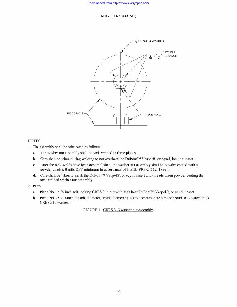
MIL-STD-2148A(SH)
58
NOTES:
1. The assembly shall be fabricated as follows:
a. The washer nut assembly shall be tack-welded in three places.
b. Care shall be taken during welding to not overheat the DuPont™ Vespel®, or equal, locking insert.
c. After the tack-welds have been accomplished, the washer nut assembly shall be powder coated with a
powder coating 8 mils DFT minimum in accordance with MIL-PRF-24712, Type I.
d. Care shall be taken to mask the DuPont™ Vespel®, or equal, insert and threads when powder coating the
tack-welded washer nut assembly.
2. Parts:
a. Piece No. 1: ⅜-inch self-locking CRES 316 nut with high heat DuPont™ Vespel®, or equal, insert.
b. Piece No. 2: 2.0-inch outside diameter, inside diameter (ID) to accommodate a ⅜-inch stud, 0.125-inch thick
CRES 316 washer.
FIGURE 1. CRES 316 washer nut assembly.
PIECE NO. 2 PIECE NO. 1
116
14
PT 1S.1
3 TACKS
OF NUT & WASHERCL
Downloaded from http://www.everyspec.com
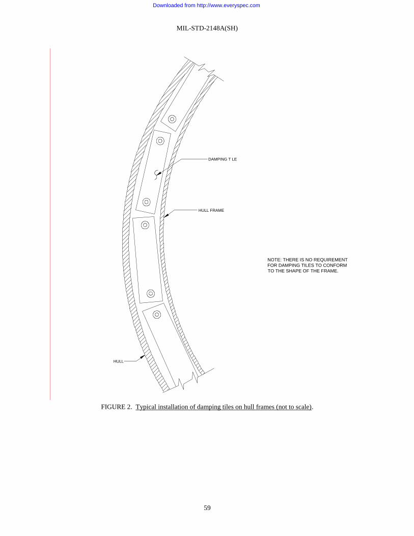
MIL-STD-2148A(SH)
59
FIGURE 2. Typical installation of damping tiles on hull frames (not to scale).
DAMPING T LE
HULL FRAME
NOTE: THERE IS NO REQUIREMENT
FOR DAMPING TILES TO CONFORM
TO THE SHAPE OF THE FRAME.
HULL
Downloaded from http://www.everyspec.com
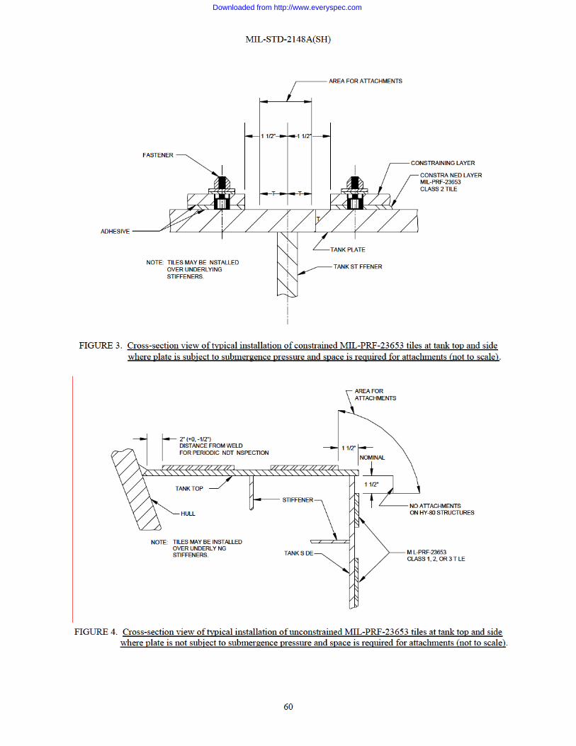
Downloaded from http://www.everyspec.com

Downloaded from http://www.everyspec.com

Downloaded from http://www.everyspec.com

MIL-STD-2148A(SH)
63
FIGURE 7. Cross-section view of typical installation of constrained MIL-PRF-23653 tiles on web of submarine
hull frame (not to scale).
STEEL HULL
1" (±1/2")
1" (±1/2")
CONSTRAINING
LAYER
M L-PRF-23653
CLASS 2, TILE
FRAME WEB
1 1/2"
11" MAX
1 1/2"
Downloaded from http://www.everyspec.com

MIL-STD-2148A(SH)
64
FIGURE 8. Cross-section view of installation of MIL-PRF-23653 tiles to underside of platform deck (not to
scale).
FIGURE 9. Cross-section view of typical damped deck beam connected to hull frame (not to scale).
MIL-PRF-23653
CLASS 2, TILES
1"(±1/2")
DECK PLATE
DECK BEAM
DAMPING
1"
DECK PLATE
HULL
FRAME DAMP NG
(SEE FIGURES 1 AND 7)
FRAME
5" M NIMUM
Downloaded from http://www.everyspec.com

MIL-STD-2148A(SH)
65
FIGURE 10. Installation of constrained, restrained, and free-layered damping tiles in way of weld beads on plane
surfaces.
FIGURE 11. Installation of damping around stiffeners in submarine superstructure and fairwater areas (not to
scale).
RESTRA N NG OR
CONSTRAINING COVER
PLATE WHERE APPLICABLE
TILE
WELD BEAD
STEEL STRUCTURE
"N"
"N" DIMENSIONS
WELDS SUBJECT TO PERIODIC MAGNETIC
PARTICLE OR EDDY CURRENT INSPECTIONWELDS NOT SUBJECT TO PERIODIC MAGNETIC
PARTICLE OR EDDY CURRENT INSPECTION
TREATMENT "N" D MENSION,
NCHESTREATMENT
"N" DIMENSION,
NCHES
CONSTRAINED,
RESTRAINED
&
FREE-
LAYERED
CONSTRAINED,
RESTRA NED
&
FREE-
LAYERED
2 0± 1.0±0 500.5
"N" DIMENSIONS SHALL BE 3 0 INCHES (+0.5 NCH, -0 0) IN FORWARD TR M TANK OF SSN'S.
DAMPING TILE
1/2"
(NOMINAL)
STIFFENER
Downloaded from http://www.everyspec.com

MIL-STD-2148A(SH)
66
FIGURE 12. Dimensions of a dog-eared trowel.
LENGTH
TO SUIT
3" MIN
4" MAX
1/8"
ADDITIONAL EAR IN
CENTER IS OPTIONAL
1/8"
2"
Downloaded from http://www.everyspec.com

Downloaded from http://www.everyspec.com
MIL-STD-2148A(SH)
68
Preparing activity:
Navy – SH
(Project 93GP-2009-001)
NOTE: The activities listed above were interested in this document as of the date of this document. Since
organizations and responsibilities can change, you should verify the currency of the information above using the
ASSIST Online database at https://assist.dla.mil.
Downloaded from http://www.everyspec.com