department of defense handbookeveryspec.com/mil-hdbk/mil-hdbk-1800-1999/download...ipc–2141 –...
TRANSCRIPT

MIL–HDBK–1861B W/CHANGE 1 20 October 2014 SUPERSEDING MIL–HDBK–1861B 18 October 2013
DEPARTMENT OF DEFENSE HANDBOOK
SELECTION AND USE OF
ELECTRICAL AND ELECTRONIC ASSEMBLIES,
BOARDS, CARDS, AND ASSOCIATED HARDWARE
This handbook is for guidance only. Do not cite this document as a requirement.
AMSC N/A FSC 5998
INCH-POUND
Downloaded from http://www.everyspec.com

MIL–HDBK–1861B W/CHANGE 1
FOREWORD 1. This handbook is approved for use by all Departments and Agencies of the Department of Defense. 2. This handbook is for guidance only. This handbook cannot be cited as a requirement. If it is, the contractor does not have to comply. 3. This handbook provides a list of electrical and electronic assemblies, boards, cards, and associated hardware for use in the design of Department of Defense equipment. The application information and performance characteristics contained in this handbook are offered for guidance and are not to be considered as binding. Additions to this handbook will be made periodically as the referenced documents are updated. 4. Comments, suggestions, or questions on this document should be addressed to: DLA Land and Maritime, ATTN: VAC, Post Office Box 3990, Columbus, OH 43218–3990 or emailed to [email protected]. Since contact information can change, you may want to verify the currency of this address information using the ASSIST Online database at https://assist.dla.mil.
ii
Downloaded from http://www.everyspec.com
MIL–HDBK–1861B W/CHANGE 1
CONTENTS PARAGRAPH PAGE FOREWORD ..ii 1. SCOPE .............................................................................................................................................................. 1
1.1 Scope ........................................................................................................................................................... 1 1.2 Purpose of this handbook ............................................................................................................................. 1
2. APPLICABLE DOCUMENTS ............................................................................................................................. 1
2.1 General ......................................................................................................................................................... 1 2.2 Government documents ............................................................................................................................... 1
2.2.1 Specifications, standards, and handbooks ............................................................................................. 1 2.2.2 Other Government documents, drawings, and publications ................................................................... 2
2.3 Non-Government publications ...................................................................................................................... 2 2.4 Order of precedence..................................................................................................................................... 2
3. REQUIREMENTS .............................................................................................................................................. 3
3.1 Definitions ..................................................................................................................................................... 3 3.1.1 Commercial Item Description (CID) ....................................................................................................... 3 3.1.2 DLA Land and Maritime drawing ............................................................................................................ 3 3.1.3 General specification.............................................................................................................................. 3 3.1.4 Parts Management Advisory Team (PMAT) ........................................................................................... 3 3.1.5 Part or Identifying Number (PIN) ............................................................................................................ 3 3.1.6 Qualified Manufacturer List (QML) .................................................................................................... 3 3.1.7 Qualified Products List (QPL) ................................................................................................................. 3
3.2 Other terms and definitions .......................................................................................................................... 3 4. GENERAL GUIDANCE ...................................................................................................................................... 3
4.1 Item identification ......................................................................................................................................... 3 4.2 Conflict of requirements ................................................................................................................................ 3 4.3 Criteria for inclusion in this handbook ........................................................................................................... 3 4.4 Order of preference ...................................................................................................................................... 4
5. DETAILED DESIGN GUIDANCE ....................................................................................................................... 4
5.1 Detailed design guidance ............................................................................................................................. 4 6. NOTES ............................................................................................................................................................... 4
6.1 Intended use ................................................................................................................................................. 4 6.2 Subject term (key word) listings .................................................................................................................... 4 6.3 Tin whisker growth........................................................................................................................................ 4 6.4 Environmentally preferable material ............................................................................................................. 4 6.5 Changes from previous issue ....................................................................................................................... 4
ELECTRICAL AND ELECTRONIC ASSEMBLIES .................................................................................................. 5 A.1 SCOPE ............................................................................................................................................................ 5
A.1.1 Scope ........................................................................................................................................................ 5 A.2 BACKPLANE ASSEMBLIES ............................................................................................................................ 5
A.2.1 Backplane printed wiring assemblies ........................................................................................................ 5 A.2.2 Metal electrical backplane assemblies ...................................................................................................... 5
iii
Downloaded from http://www.everyspec.com

MIL–HDBK–1861B W/CHANGE 1
CONTENTS PARAGRAPH PAGE PRINTED CIRCUIT BOARDS AND PRINTED WIRING BOARDS ......................................................................... 7 B.1 SCOPE ............................................................................................................................................................ 7
B.1.1 Scope ........................................................................................................................................................ 7 B.2 PRINTED CIRCUIT AND PRINTED WIRING BOARDS .................................................................................. 7
B.2.1 Rigid printed circuit and printed wiring boards .......................................................................................... 7 B.2.2 Flexible and rigid–flex printed wiring ......................................................................................................... 7 B.2.3 High frequency and high speed printed circuit boards .............................................................................. 7
B.3. DESIGN GUIDELINES ................................................................................................................................... 7
B.3.1 Printed board size ..................................................................................................................................... 7 B.3.2 Current-carrying capacity of printed wiring boards .................................................................................... 7
CARD GUIDES ....................................................................................................................................................... 9 C.1 SCOPE ............................................................................................................................................................ 9
C.1.1 Scope ........................................................................................................................................................ 9 C.2 APPLICABLE DOCUMENTS ........................................................................................................................... 9
C.2.1 Metal card guides...................................................................................................................................... 9 C.2.2 Plastic card guides .................................................................................................................................... 9
CARD HOLDERS .................................................................................................................................................. 27 D.1 SCOPE .......................................................................................................................................................... 27
D.1.1 Scope ...................................................................................................................................................... 27 D.2 WEDGE STYLE CARD HOLDERS ............................................................................................................... 27
D.2.1 Three body wedge card holders ............................................................................................................. 27 D.2.2 Five body wedge card holders ................................................................................................................ 27 D.2.3 Seven body wedge card holders ............................................................................................................. 27
EXTRACTORS AND RETAINER–EJECTORS ..................................................................................................... 39 E.1 SCOPE .......................................................................................................................................................... 39
E.1.1 Scope ...................................................................................................................................................... 39 E.2 EXTRACTORS AND RETAINER–EJECTORS .............................................................................................. 39
E.2.1 Metal extractors....................................................................................................................................... 39 E.2.2 Heavy duty metal extractors .................................................................................................................... 39 E.2.3 Retainer–ejectors .................................................................................................................................... 39
iv
Downloaded from http://www.everyspec.com

MIL–HDBK–1861B W/CHANGE 1
CONTENTS APPENDIX PAGE A ELECTRICAL AND ELECTRONIC ASSEMBLIES ................................................................................ 5 B PRINTED CIRCUIT BOARDS AND PRINTED WIRING BOARDS ....................................................... 7 C CARD GUIDES ..................................................................................................................................... 9 D CARD HOLDERS ................................................................................................................................ 27 E EXTRACTORS AND RETAINER–EJECTORS ................................................................................... 39 FIGURES PAGE C–1 Card guides, metal, medium profile, with center mounting hole ................................................................. 16 D–1 Relaxed and expanded dimensions, lever actuated 3 body wedge card holders ....................................... 28 D–2 Relaxed and expanded dimensions, ejection action 3 body wedge card holders ....................................... 29 D–3 Relaxed and expanded dimensions, screw actuated 3 body wedge card holders...................................... 30 D–4 Relaxed and expanded dimensions, screw actuated 5 body wedge card holders, various body sizes ...... 35 D–5 Relaxed and expanded dimensions, screw actuated 7 body wedge card holders, various body sizes ...... 37
TABLES PAGE C–I Card guides, metal, with 2 offset mounting holes .................................................................................. 10 C–II Card guides, metal, with 2 center mounting holes or studs ................................................................... 12 C–III Card guides, metal, with 3 offset mounting holes .................................................................................. 14 C–IV Card guides, metal, medium profile, with center mounting holes .......................................................... 16 C–V Card guides, metal, with 3 center mounting holes or studs ................................................................... 17 C–VI Card guides, metal, slot width .0625 inch (1.59 mm) ............................................................................ 19 C–VII Card guides, metal, slot width .0937 inch (2.38 mm) ............................................................................ 20 C–VIII Card guides, metal, slot width .125 inch (3.18 mm) .............................................................................. 21 C–IX Card guides, metal, screw actuated, slot width .025 to .079 inch (0.64 to 2.01 mm) ............................ 22 C–X Card guides, metal, screw actuated, slot width .080 to .145 inch (2.03 to 3.68 mm) ............................ 23 C–XI Card guides, metal, lever actuated, slot width .211 inch (5.36 mm) + PWB thickness .......................... 24 C–XII Card guides, plastic, pylon mounted, shallow slot, slot width .078 inch (1.98 mm) ............................... 24 C–XIII Card guides, plastic, pylon mounted, deep slot, slot width .080 to .132 inch (2.0 to 3.4 mm) ............... 25 C–XIV Card guides, plastic, slot width .050 to .100 inch (1.27 to 2.54 mm) ..................................................... 25 C–XV Card guide, plastic, fastener mounted, shallow slot, slot width .070 inch (1.78 mm) ............................ 25
v
Downloaded from http://www.everyspec.com
MIL–HDBK–1861B W/CHANGE 1
CONTENTS
TABLES - Continued PAGE
D–I Card holders, 3 body wedge retainer, with lever action locking ............................................................ 28 D–II Card holders, 3 body wedge retainer, with ejection action .................................................................... 29 D–III Card holders, 3 body wedge retainer, .225 by .260 inch (5.72 x 6.61 mm) body size ........................... 30 D–IV Card holders, 3 body wedge retainer, .220 by .220 inch (5.59 x 5.9 mm) body size ............................. 31 D–V Card holders, 3 body wedge retainer, .240 by .180 inch (6.1 x 4.57 mm) body size ............................. 32 D–VI Card holders, 3 body wedge retainer, .375 by .375 inch (9.53 x 9.53 mm) body size ........................... 32 D–VII Card holders, 3 body wedge retainer, .260 by .260 inch (6.61 x 6.61 mm) body size ........................... 33 D–VIII Card holders, 3 body wedge retainer, .500 by .450 inch (12.7 x 11.43 mm) body size ......................... 33 D–IX Card holders, 3 body wedge retainer, various body sizes ..................................................................... 33 D–X Card holders, 5 body wedge retainer, .250 by .260 (6.35 x 6.61 mm) body size .................................. 34 D–XI Card holders, 5 body wedge retainer, various body sizes ..................................................................... 34 D–XII Card holders, 5 body wedge retainer, various body sizes ..................................................................... 35 D–XIII Card holders, 5 body wedge retainer, 225 x .225 inch (5.72 x 5.72 mm) body size .............................. 36 D–XIV Card holders, 7 body wedge retainer, .250 x .260 inch (6.35 x 6.61 mm) body size ............................. 36 E–I Extractor, electrical card, metal, without locking tab ............................................................................. 39 E–II Extractor, electrical card, metal, with locking tab .................................................................................. 40 E–III Extractor, electrical card, metal, heavy duty .......................................................................................... 41 E–IV Retainer–ejector, electrical card, plastic................................................................................................ 42
vi
Downloaded from http://www.everyspec.com

MIL–HDBK–1861B W/CHANGE 1
1. SCOPE
1.1 Scope. This handbook is for guidance only and cannot be cited as a requirement. If it is, the contractor does
not have to comply. This handbook consists of the following:
a. Selected standard items, for use in the design and manufacturer of Department of Defense equipment under the jurisdiction of the Department of Defense.
b. Guides for the choice and application of items for use in Department of Defense equipment.
1.2 Purpose of this handbook.
a. To provide the equipment designer with a selection of standard items for use in most Department of Defense
applications. b. To control and minimize the variety of items used in Department of Defense equipment in order to facilitate
logistic support of equipment in the field. c. To outline criteria pertaining to the use, choice, and application of items in Department of Defense
equipment.
2. APPLICABLE DOCUMENTS
2.1 General. The documents listed below are not necessarily all of the documents referenced herein, but are those needed to understand the information provided by this handbook.
2.2 Government documents.
2.2.1 Specifications, standards, and handbooks. The following specifications, standards, and handbooks form a part of this document to the extent specified herein.
DEPARTMENT OF DEFENSE SPECIFICATIONS
MIL–A–24741 – Assemblies, Metal Electrical Backplane, One and Two Layer, General Specification for. MIL–A–28870 – Assemblies, Electrical Backplane, Printed Wiring, General Specification for. MIL–PRF–31032 – Printed Circuit Board/Printed Wiring Board, General Specification for. A–A–55563 – Holder, Electrical Card, Metal Card Guide, General Requirements for. A–A–59590 – Holder, Electrical Card, Wedge Retainers, 3 Piece, Screw Actuate Drive, General
Requirements for. A–A–59789 – Holder, Electrical Card, Wedge Retainers, 5 Piece, For Cold Plate Applications, General
Requirements for. A–A–59812 – Holder, Electrical Card, Metal Card Guide, Multiple Piece, General Requirements for. A–A–59832 – Extractor, Electrical Card, Metal, General Requirements for. A–A–59950 – Holder, Electrical Card, Wedge Retainers, 7 Piece, For Cold Plate Applications, General
Requirements for.
DEPARTMENT OF DEFENSE STANDARDS
MIL–STD–2119 – Design Requirements for Printed–Wiring Electrical Backplane Assemblies. MIL–STD–2198 – Design Requirements for Metal Electrical Backplane Assemblies.
(Copies of these documents are available online at http://quicksearch.dla.mil.)
1
Downloaded from http://www.everyspec.com
MIL–HDBK–1861B W/CHANGE 1
2.2.2 Other Government documents, drawings, and publications. The following other Government documents,
drawings, and publications form a part of this document to the extent specified herein.
DRAWINGS
83023 – Retainer–Ejector, Electrical Card, Plastic. 84006 – Holder, Electrical Card, Card Guide, Shallow Channel, Plastic. 84101 – Holder, Electrical Card, Card Guide, Deep Channel, Plastic. 84103 – Holder, Electrical Card, Wedge Retainer, 3–Piece, Screw Actuated. 84168 – Holder, Electrical Card, Card Guide–Retainer, Lever Actuated, Metal. 84191 – Extractor, Electrical Card, Metal. 85033 – Holder, Electrical Card, Metal Card Guide, Zero Insertion Force. 85034 – Holder, Electrical Card, Metal, Card Guide. 85067 – Holder, Electrical Card, Card Guide, Non–Conductive Plastic, Anti–vibration. 85068 – Holder, Electrical Card, Card Guide, Plastic, Fastener Mounted. 86092 – Holder, Electrical Card, Card Guide–Retainer, Lever Actuated, Metal. 88052 – Holder, Electrical Card, Card Guide–Retainer, Screw Actuated, Metal. 89024 – Holder, Electrical Card, Wedge Retainer, 5–Piece, .250 Inch By .260 Inch Body Size. 89029 – Holder, Electrical Card, Card Guide, Conductive Plastic, Anti–vibration. 89064 – Holder, Electrical Card, Wedge Retainer, 5–Piece, .225 Inch by .225 Inch and .225 Inch By .260
Inch Body Size.
(Copies of these documents are available online at http://www.landandmaritime.dla.mil/Programs/MilSpec.)
2.3 Non–Government publications. The following documents form a part of this document to the extent specified herein.
IPC – ASSOCIATION CONNECTING ELECTRONICS INDUSTRIES (IPC)
IPC–2141 – Design Guide for High-Speed Controlled Impedance Circuit Boards. IPC–2152 – Design Standard for Determining Current-Carrying Capacity in Printed Board Design. IPC–2221 – Generic Standard on Printed Board Design. IPC–2223 – Sectional Design Standard for Flexible Printed Boards. IPC–2226 – Sectional Design Standard for High Density Interconnect (HDI) Printed Boards. IPC–2251 – Design Guide for the Packaging of High Speed Electronic Circuits. IPC–2615 – Printed Board Dimensions and Tolerances. IPC–T–50 – Terms and Definitions for Interconnecting and Packaging Electronic Circuits. IPC–D–322 – Guidelines for Selecting Printed Wiring Board Sizes Using Standard Panel Sizes.
(Application for copies should be addressed to IPC – Association Connecting Electronics Industries, 3000 Lakeside Drive, Suite 309 S, Bannockburn, IL 60015–1249 or http://www.ipc.org.)
2.4 Order of precedence. Unless otherwise noted herein or in the contract, in the event of a conflict between the text of this document and the references cited herein, the text of this document takes precedence. Nothing in this document, however, supersedes applicable laws and regulations unless a specific exemption has been obtained.
2
Downloaded from http://www.everyspec.com

MIL–HDBK–1861B W/CHANGE 1
3. DEFINITIONS
3.1 Definitions.
3.1.1 Commercial Item Description (CID). A simplified product description that describes, by functional or
performance characteristics, the available, acceptable commercial products that will satisfy the Government’s needs.
3.1.2 DLA Land and Maritime drawing. A standardization document developed by, and available from, the Defense Supply Center, Columbus.
3.1.3 General specification. A general specification is prepared in the six–section format and covers requirements and test procedures that are common to a group of parts, materials, or equipment. It is used with specification sheets and master drawings; e.g., MIL–PRF–31032 for printed boards.
3.1.4 Parts Management Advisory Team (PMAT). A DoD organization which provides advice to the Department of Defense departments and contractors on the selection of parts in assigned commodity classes, and collects data on nonstandard parts for developing and updating Department of Defense specifications and standards.
3.1.5 Part or Identifying Number (PIN). Formerly part number (P/N).
3.1.6 Qualified Manufacturer List (QML). A document maintained by the Government qualifying activity which lists vendors who are officially approved by the Government.
3.1.7 Qualified Products List (QPL). A document maintained by the Government qualifying activity which lists vendors whose products are officially approved by the Government.
3.2 Other terms and definitions. Other terms and definitions may be found in IPC–T–50.
4. GENERAL GUIDANCE
4.1 Item identification. PIN's and type designations are used to identify the items listed in this handbook and in the individual specifications.
4.2 Conflict of requirements. In the event of conflict between the technical requirements of items described in this handbook and the applicable specification or DLA Land and Maritime drawing, the specification or DLA Land and Maritime drawing should govern.
4.3 Criteria for inclusion in this handbook. The criteria for inclusion in this handbook are as follows:
a. The items are classified in FSC 5998. b. The items are for general use in DoD equipment. c. The items are covered by CIDs, DoD specifications, or DLA Land and Maritime drawings. d. The items are available from at least one source. e. The items are to be used for design purposes in new equipment.
3
Downloaded from http://www.everyspec.com

MIL–HDBK–1861B W/CHANGE 1
4.4 Order of preference. The order of preference is as follows:
a. Non–Government Standard (NGS) parts. b. CID parts. c. DoD QML specification parts. d. DoD QPL specification parts. e. DoD drawing parts. f. Other parts.
5. DETAILED DESIGN GUIDANCE
5.1 Detailed design guidance. The detailed guidance for electrical and electronic assemblies, boards, cards, and
associated hardware are contained in the applicable appendices of this handbook.
6. NOTES
6.1 Intended use. The purpose of this handbook is to provide standardized guidance in the preparation of DoD standards, handbooks, drawings, and bulletins to ensure the inclusion of data and descriptions essential to the selection and application of items and processes, and to aid in the use and analysis of DoD standardization documents.
6.2 Subject term (key word) listings.
Backplane assembly Circuit card assembly Extractor, electrical card Holder, electrical card Printed circuit board Printed wiring board Retainer–ejector, electrical card
6.3 Tin whisker growth. The use of alloys with tin content greater than 97 percent, by mass, may exhibit tin
whisker growth problems after manufacture. Tin whiskers may occur anytime from a day to years after manufacture and can develop under typical operating conditions, on products that use such materials. Conformal coatings applied over top of a whisker-prone surface will not prevent the formation of tin whiskers. Alloys of 3 percent lead, by mass, have shown to inhibit the growth of tin whiskers. For additional information on this matter, refer to ASTM-B545 (Standard Specification for Electrodeposited Coatings of Tin).
6.4 Environmentally preferable material. Environmentally preferable materials should be used to the maximum extent possible to meet the requirements of this specification. As of the dating of this document, the U.S. Environmental Protection Agency (EPA) is focusing efforts on reducing 31 priority chemicals. The list of chemicals and additional information is available on their website http://www.epa.gov/osw/hazard/wastemin/priority.htm. Use of these materials should be minimized or eliminated unless needed to meet the requirements specified herein
6.5 Changes from previous issue. The margins of this handbook are marked with vertical lines to indicate where changes from the previous issue were made. This was done as a convenience only and the Government assumes no liability whatsoever for any inaccuracies in these notations.
4
Downloaded from http://www.everyspec.com

MIL–HDBK–1861B W/CHANGE 1
APPENDIX A
ELECTRICAL AND ELECTRONIC ASSEMBLIES
A.1 SCOPE
A.1.1 Scope. This appendix covers active DoD specifications for electrical and electronic backplane assemblies.
A.2 BACKPLANE ASSEMBLIES.
A.2.1 Backplane printed wiring assemblies. Electrical backplane printed wiring assemblies conformance information can be found in MIL–A–28870 and design information can be found in MIL–STD–2119.
A.2.2 Metal electrical backplane assemblies. Metal electrical backplane assemblies conformance information can be found in MIL–A–24741 and design information can be found in MIL–STD–2198.
5
Downloaded from http://www.everyspec.com

MIL–HDBK–1861B W/CHANGE 1
APPENDIX A
This page intentionally left blank.
6
Downloaded from http://www.everyspec.com

MIL–HDBK–1861B W/CHANGE 1
APPENDIX B
PRINTED CIRCUIT BOARDS AND PRINTED WIRING BOARDS
B.1 SCOPE
B.1.1 Scope. This appendix covers active DoD specifications used for printed circuit boards and printed wiring boards.
B.2 PRINTED CIRCUIT AND PRINTED WIRING BOARDS
B.2.1 Rigid printed circuit and printed wiring boards. Rigid printed circuit and printed wiring boards for single–sided, double–sided, and multilayer printed wiring performance and verification information can be found in MIL–PRF–31032. The design of rigid printed boards are detailed in IPC–2221 and IPC–2226.
B.2.2 Flexible and rigid–flex printed wiring. Flexible and rigid–flex printed wiring performance and verification information can be found in MIL–PRF–31032. The design of flexible and rigid-flex printed wiring boards are detailed in IPC–2221 and IPC–2223.
B.2.3 High frequency and high speed printed circuit boards. The performance and verification information for printed circuit boards designed for high frequency and high speed applications can be found in MIL–PRF–31032. The design of high frequency and high speed printed circuit boards are detailed in IPC–2221, IPC–2141, and IPC–2251.
B.3 DESIGN GUIDELINES
B.3.1 Printed board size. Whenever cost and technical requirements permit, preferred rigid printed board sizes should be used. These printed board sizes will facilitate the development and use of standardized insertion and extraction tools. The preferred printed board sizes, are detailed in IPC–2221. Additional guidelines for selecting printed board sizes can be found in IPC–D–322. Printed board dimensions and tolerances should be in accordance with IPC–2615.
B.3.2 Current-carrying capacity of printed wiring boards. The thickness and width of conductors on the finished printed board should be determined on the basis of the signal characteristics, current carrying capacity required and the maximum allowable temperature rise. IPC–2152 should be used for determining the current carrying capacity and sizes of etched copper conductors for various temperature rises above ambient temperature.
7
Downloaded from http://www.everyspec.com

MIL–HDBK–1861B W/CHANGE 1
APPENDIX B
This page intentionally left blank.
8
Downloaded from http://www.everyspec.com
MIL–HDBK–1861B W/CHANGE 1
APPENDIX C
CARD GUIDES
C.1. SCOPE
C.1.1 Scope. This appendix covers commercial item descriptions and drawings used for card guides. The parts described by these commercial item descriptions and drawings and are used to supplement Military specifications.
C.2. ELECTRICAL CARD GUIDES
C.2.1 Metal card guides. Metal card guide selections are found in tables C–I through C–XI.
C.2.2 Plastic card guides. Plastic card guide selections are found in tables C–XII through C–XV.
9
Downloaded from http://www.everyspec.com
MIL–HDBK–1861B W/CHANGE 1
APPENDIX C
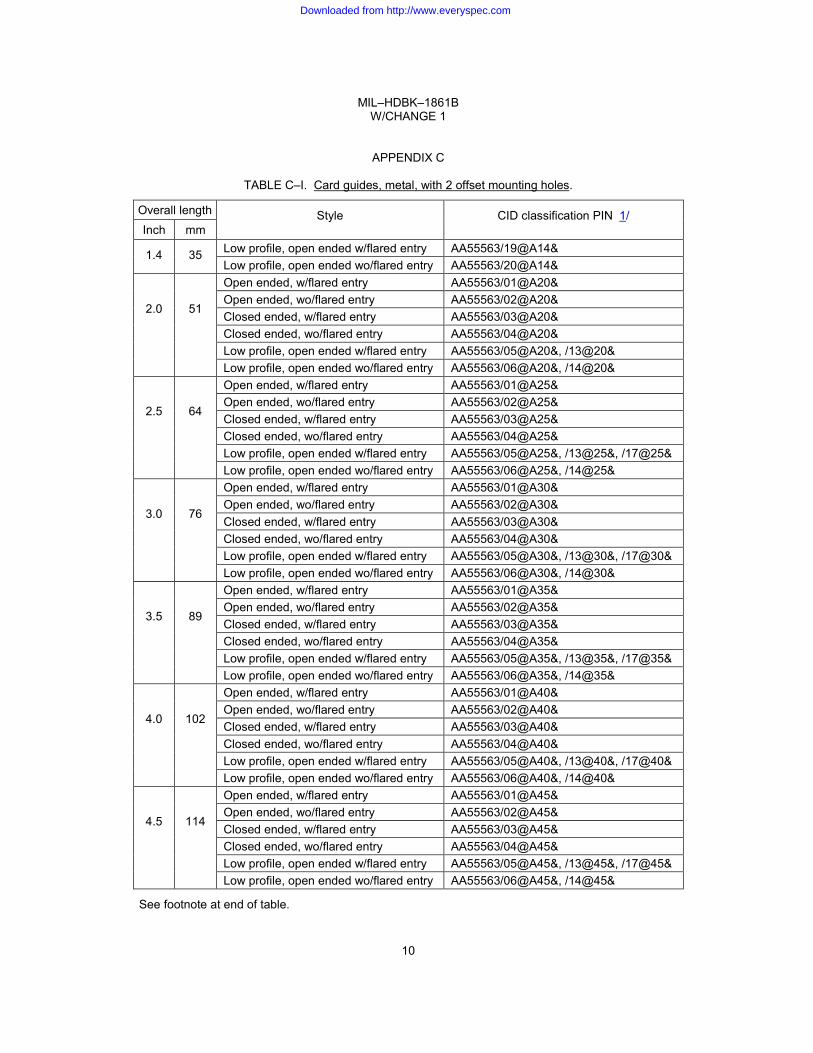
TABLE C–I. Card guides, metal, with 2 offset mounting holes.
Overall length Style CID classification PIN 1/ Inch mm
1.4 35 Low profile, open ended w/flared entry AA55563/19@A14& Low profile, open ended wo/flared entry AA55563/20@A14&
2.0
51
Open ended, w/flared entry AA55563/01@A20& Open ended, wo/flared entry AA55563/02@A20& Closed ended, w/flared entry AA55563/03@A20& Closed ended, wo/flared entry AA55563/04@A20& Low profile, open ended w/flared entry AA55563/05@A20&, /13@20& Low profile, open ended wo/flared entry AA55563/06@A20&, /14@20&
2.5
64
Open ended, w/flared entry AA55563/01@A25& Open ended, wo/flared entry AA55563/02@A25& Closed ended, w/flared entry AA55563/03@A25& Closed ended, wo/flared entry AA55563/04@A25& Low profile, open ended w/flared entry AA55563/05@A25&, /13@25&, /17@25& Low profile, open ended wo/flared entry AA55563/06@A25&, /14@25&
3.0
76
Open ended, w/flared entry AA55563/01@A30& Open ended, wo/flared entry AA55563/02@A30& Closed ended, w/flared entry AA55563/03@A30& Closed ended, wo/flared entry AA55563/04@A30& Low profile, open ended w/flared entry AA55563/05@A30&, /13@30&, /17@30& Low profile, open ended wo/flared entry AA55563/06@A30&, /14@30&
3.5
89
Open ended, w/flared entry AA55563/01@A35& Open ended, wo/flared entry AA55563/02@A35& Closed ended, w/flared entry AA55563/03@A35& Closed ended, wo/flared entry AA55563/04@A35& Low profile, open ended w/flared entry AA55563/05@A35&, /13@35&, /17@35& Low profile, open ended wo/flared entry AA55563/06@A35&, /14@35&
4.0
102
Open ended, w/flared entry AA55563/01@A40& Open ended, wo/flared entry AA55563/02@A40& Closed ended, w/flared entry AA55563/03@A40& Closed ended, wo/flared entry AA55563/04@A40& Low profile, open ended w/flared entry AA55563/05@A40&, /13@40&, /17@40& Low profile, open ended wo/flared entry AA55563/06@A40&, /14@40&
4.5
114
Open ended, w/flared entry AA55563/01@A45& Open ended, wo/flared entry AA55563/02@A45& Closed ended, w/flared entry AA55563/03@A45& Closed ended, wo/flared entry AA55563/04@A45& Low profile, open ended w/flared entry AA55563/05@A45&, /13@45&, /17@45& Low profile, open ended wo/flared entry AA55563/06@A45&, /14@45&
See footnote at end of table.
10
Downloaded from http://www.everyspec.com

MIL–HDBK–1861B W/CHANGE 1
APPENDIX C
TABLE C–I. Card guides, metal, with 2 offset mounting holes – Continued.
Overall length Style CID classification PIN 1/ Inch mm
5.0
127
Open ended, w/flared entry AA55563/01@A50& Open ended, wo/flared entry AA55563/02@A50& Closed ended, w/flared entry AA55563/03@A50& Closed ended, wo/flared entry AA55563/04@A50& Low profile, open ended w/flared entry AA55563/05@A50&, /13@50&, /17@50& Low profile, open ended wo/flared entry AA55563/06@A50&, /14@50&
5.5
140
Open ended, w/flared entry AA55563/01@A55& Open ended, wo/flared entry AA55563/02@A55& Closed ended, w/flared entry AA55563/03@A55& Closed ended, wo/flared entry AA55563/04@A55& Low profile, open ended w/flared entry AA55563/05@A55&, /13@55&, /17@55& Low profile, open ended wo/flared entry AA55563/06@A55&, /14@55&
6.0
152
Open ended, w/flared entry AA55563/01@A60& Open ended, wo/flared entry AA55563/02@A60& Closed ended, w/flared entry AA55563/03@A60& Closed ended, wo/flared entry AA55563/04@A60& Low profile, open ended w/flared entry AA55563/05@A60&, /13@60&, /17@60& Low profile, open ended wo/flared entry AA55563/06@A60&, /14@60&
6.5
165
Open ended, w/flared entry AA55563/01@A20& Open ended, wo/flared entry AA55563/02@A20& Closed ended, w/flared entry AA55563/03@A20& Closed ended, wo/flared entry AA55563/04@A20& Low profile, open ended w/flared entry AA55563/05@A20&, /13@20& Low profile, open ended wo/flared entry AA55563/06@A20&, /14@20&
7.0
178
Open ended, w/flared entry AA55563/01@A70& Open ended, wo/flared entry AA55563/02@A70& Closed ended, w/flared entry AA55563/03@A70& Closed ended, wo/flared entry AA55563/04@A70& Low profile, open ended w/flared entry AA55563/05@A70&, /13@70& Low profile, open ended wo/flared entry AA55563/06@A70&, /14@70&
7.5
191
Open ended, w/flared entry AA55563/01@A75& Open ended, wo/flared entry AA55563/02@A75& Closed ended, w/flared entry AA55563/03@A75& Closed ended, wo/flared entry AA55563/04@A75& Low profile, open ended w/flared entry AA55563/05@A75&, /13@75& Low profile, open ended wo/flared entry AA55563/06@A75&, /14@75&
1/ The at sign (@) represents one of the four materials available, the letter "A" represents one of three materials available, and the ampersands (&) represents the one of the 11 protective finishes available.
11
Downloaded from http://www.everyspec.com

MIL–HDBK–1861B W/CHANGE 1
APPENDIX C
TABLE C–II. Card guides, metal, with 2 center mounting holes or studs.
Overall length Style CID classification PIN 1/ Inch mm
2.0 51 Hole mounted, left hand facing AA59812/01L20$&; AA59812/02L20$&; Hole mounted, right hand facing AA59812/01R20$&; AA59812/02L20$&; Stud mounted, left hand facing AA59812/01S20$&; AA59812/02L20$&; Stud mounted, right hand facing AA59812/01T20$&; AA59812/02L20$&;
2.5
64
Hole mounted, left hand facing AA59812/01L25$&; AA59812/02L25$&; Hole mounted, right hand facing AA59812/01R25$&; AA59812/02L25$&; Stud mounted, left hand facing AA59812/01S25$&; AA59812/02L25$&; Stud mounted, right hand facing AA59812/01T25$&; AA59812/02L25$&;
3.0
76
Hole mounted, left hand facing AA59812/01L30$&; AA59812/02L30$&; Hole mounted, right hand facing AA59812/01R30$&; AA59812/02L30$&; Stud mounted, left hand facing AA59812/01S30$&; AA59812/02L30$&; Stud mounted, right hand facing AA59812/01T30$&; AA59812/02L30$&;
3.5
89
Hole mounted, left hand facing AA59812/01L35$&; AA59812/02L35$&; Hole mounted, right hand facing AA59812/01R35$&; AA59812/02L35$&; Stud mounted, left hand facing AA59812/01S35$&; AA59812/02L35$&; Stud mounted, right hand facing AA59812/01T35$&; AA59812/02L35$&;
4.0
102
Hole mounted, left hand facing AA59812/01L40$&; AA59812/02L40$&; Hole mounted, right hand facing AA59812/01R40$&; AA59812/02L40$&; Stud mounted, left hand facing AA59812/01S40$&; AA59812/02L40$&; Stud mounted, right hand facing AA59812/01T40$&; AA59812/02L40$&;
4.5
114
Hole mounted, left hand facing AA59812/01L45$&; AA59812/02L45$&; Hole mounted, right hand facing AA59812/01R45$&; AA59812/02L45$&; Stud mounted, left hand facing AA59812/01S45$&; AA59812/02L45$&; Stud mounted, right hand facing AA59812/01T45$&; AA59812/02L45$&;
5.0
127
Hole mounted, left hand facing AA59812/01L50$&; AA59812/02L50$&; Hole mounted, right hand facing AA59812/01R50$&; AA59812/02L50$&; Stud mounted, left hand facing AA59812/01S50$&; AA59812/02L50$&; Stud mounted, right hand facing AA59812/01T50$&; AA59812/02L50$&;
5.5
140
Hole mounted, left hand facing AA59812/01L55$&; AA59812/02L55$&; Hole mounted, right hand facing AA59812/01R55$&; AA59812/02L55$&; Stud mounted, left hand facing AA59812/01S55$&; AA59812/02L55$&; Stud mounted, right hand facing AA59812/01T55$&; AA59812/02L55$&;
6.0
152
Hole mounted, left hand facing AA59812/01L60$&; AA59812/02L60$&; Hole mounted, right hand facing AA59812/01R60$&; AA59812/02L60$&; Stud mounted, left hand facing AA59812/01S60$&; AA59812/02L60$&; Stud mounted, right hand facing AA59812/01T60$&; AA59812/02L60$&;
See footnote at end of table.
12
Downloaded from http://www.everyspec.com
MIL–HDBK–1861B W/CHANGE 1
APPENDIX C
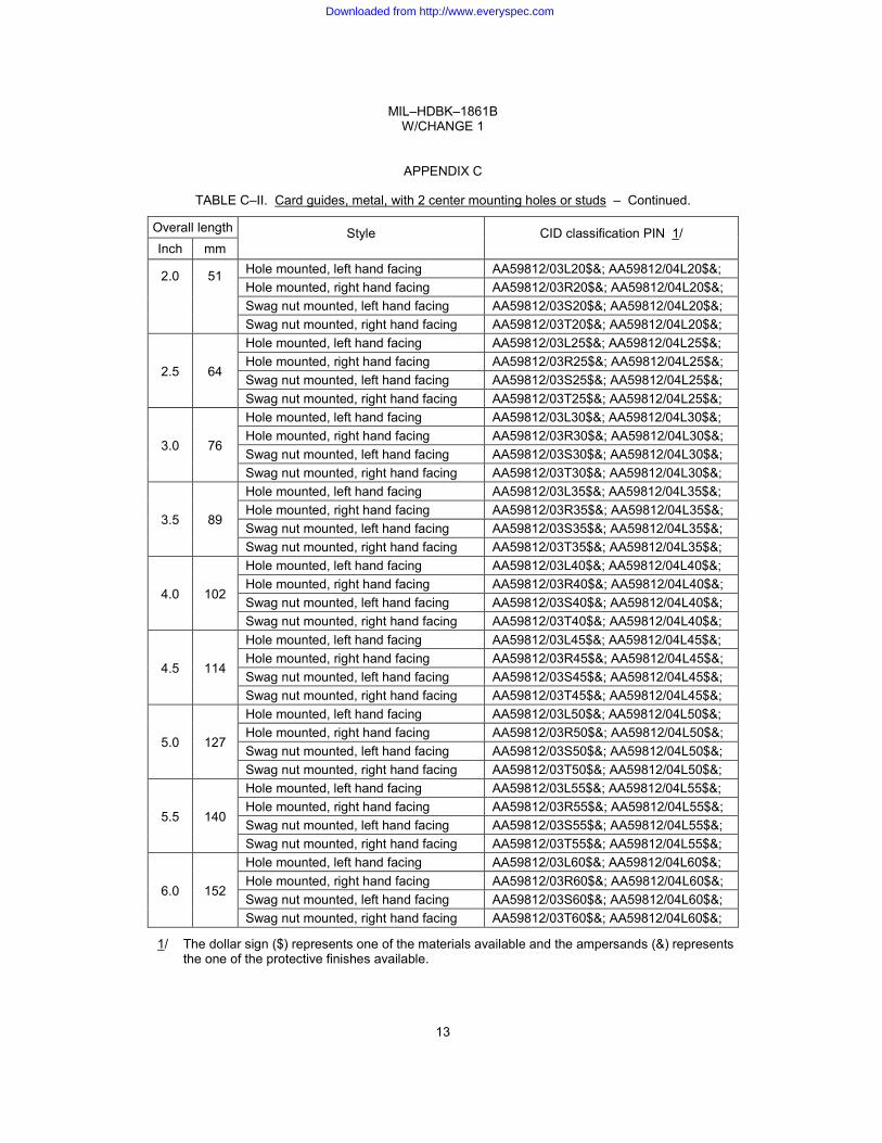
TABLE C–II. Card guides, metal, with 2 center mounting holes or studs – Continued.
Overall length Style CID classification PIN 1/ Inch mm
2.0 51 Hole mounted, left hand facing AA59812/03L20$&; AA59812/04L20$&; Hole mounted, right hand facing AA59812/03R20$&; AA59812/04L20$&; Swag nut mounted, left hand facing AA59812/03S20$&; AA59812/04L20$&; Swag nut mounted, right hand facing AA59812/03T20$&; AA59812/04L20$&;
2.5
64
Hole mounted, left hand facing AA59812/03L25$&; AA59812/04L25$&; Hole mounted, right hand facing AA59812/03R25$&; AA59812/04L25$&; Swag nut mounted, left hand facing AA59812/03S25$&; AA59812/04L25$&; Swag nut mounted, right hand facing AA59812/03T25$&; AA59812/04L25$&;
3.0
76
Hole mounted, left hand facing AA59812/03L30$&; AA59812/04L30$&; Hole mounted, right hand facing AA59812/03R30$&; AA59812/04L30$&; Swag nut mounted, left hand facing AA59812/03S30$&; AA59812/04L30$&; Swag nut mounted, right hand facing AA59812/03T30$&; AA59812/04L30$&;
3.5
89
Hole mounted, left hand facing AA59812/03L35$&; AA59812/04L35$&; Hole mounted, right hand facing AA59812/03R35$&; AA59812/04L35$&; Swag nut mounted, left hand facing AA59812/03S35$&; AA59812/04L35$&; Swag nut mounted, right hand facing AA59812/03T35$&; AA59812/04L35$&;
4.0
102
Hole mounted, left hand facing AA59812/03L40$&; AA59812/04L40$&; Hole mounted, right hand facing AA59812/03R40$&; AA59812/04L40$&; Swag nut mounted, left hand facing AA59812/03S40$&; AA59812/04L40$&; Swag nut mounted, right hand facing AA59812/03T40$&; AA59812/04L40$&;
4.5
114
Hole mounted, left hand facing AA59812/03L45$&; AA59812/04L45$&; Hole mounted, right hand facing AA59812/03R45$&; AA59812/04L45$&; Swag nut mounted, left hand facing AA59812/03S45$&; AA59812/04L45$&; Swag nut mounted, right hand facing AA59812/03T45$&; AA59812/04L45$&;
5.0
127
Hole mounted, left hand facing AA59812/03L50$&; AA59812/04L50$&; Hole mounted, right hand facing AA59812/03R50$&; AA59812/04L50$&; Swag nut mounted, left hand facing AA59812/03S50$&; AA59812/04L50$&; Swag nut mounted, right hand facing AA59812/03T50$&; AA59812/04L50$&;
5.5
140
Hole mounted, left hand facing AA59812/03L55$&; AA59812/04L55$&; Hole mounted, right hand facing AA59812/03R55$&; AA59812/04L55$&; Swag nut mounted, left hand facing AA59812/03S55$&; AA59812/04L55$&; Swag nut mounted, right hand facing AA59812/03T55$&; AA59812/04L55$&;
6.0
152
Hole mounted, left hand facing AA59812/03L60$&; AA59812/04L60$&; Hole mounted, right hand facing AA59812/03R60$&; AA59812/04L60$&; Swag nut mounted, left hand facing AA59812/03S60$&; AA59812/04L60$&; Swag nut mounted, right hand facing AA59812/03T60$&; AA59812/04L60$&;
1/ The dollar sign ($) represents one of the materials available and the ampersands (&) represents the one of the protective finishes available.
13
Downloaded from http://www.everyspec.com
MIL–HDBK–1861B W/CHANGE 1
APPENDIX C
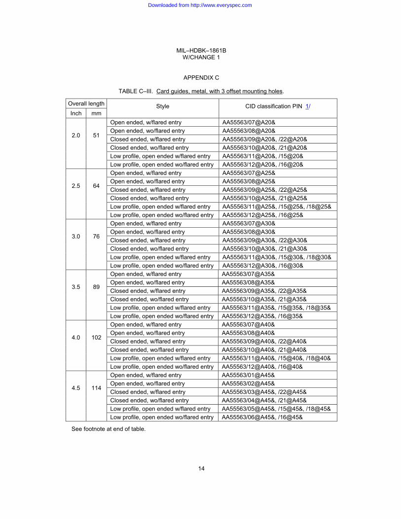
TABLE C–III. Card guides, metal, with 3 offset mounting holes.
Overall length Style CID classification PIN 1/ Inch mm
2.0
51
Open ended, w/flared entry AA55563/07@A20& Open ended, wo/flared entry AA55563/08@A20& Closed ended, w/flared entry AA55563/09@A20&, /22@A20& Closed ended, wo/flared entry AA55563/10@A20&, /21@A20& Low profile, open ended w/flared entry AA55563/11@A20&, /15@20& Low profile, open ended wo/flared entry AA55563/12@A20&, /16@20&
2.5
64
Open ended, w/flared entry AA55563/07@A25& Open ended, wo/flared entry AA55563/08@A25& Closed ended, w/flared entry AA55563/09@A25&, /22@A25& Closed ended, wo/flared entry AA55563/10@A25&, /21@A25& Low profile, open ended w/flared entry AA55563/11@A25&, /15@25&, /18@25& Low profile, open ended wo/flared entry AA55563/12@A25&, /16@25&
3.0
76
Open ended, w/flared entry AA55563/07@A30& Open ended, wo/flared entry AA55563/08@A30& Closed ended, w/flared entry AA55563/09@A30&, /22@A30& Closed ended, wo/flared entry AA55563/10@A30&, /21@A30& Low profile, open ended w/flared entry AA55563/11@A30&, /15@30&, /18@30& Low profile, open ended wo/flared entry AA55563/12@A30&, /16@30&
3.5
89
Open ended, w/flared entry AA55563/07@A35& Open ended, wo/flared entry AA55563/08@A35& Closed ended, w/flared entry AA55563/09@A35&, /22@A35& Closed ended, wo/flared entry AA55563/10@A35&, /21@A35& Low profile, open ended w/flared entry AA55563/11@A35&, /15@35&, /18@35& Low profile, open ended wo/flared entry AA55563/12@A35&, /16@35&
4.0
102
Open ended, w/flared entry AA55563/07@A40& Open ended, wo/flared entry AA55563/08@A40& Closed ended, w/flared entry AA55563/09@A40&, /22@A40& Closed ended, wo/flared entry AA55563/10@A40&, /21@A40& Low profile, open ended w/flared entry AA55563/11@A40&, /15@40&, /18@40& Low profile, open ended wo/flared entry AA55563/12@A40&, /16@40&
4.5
114
Open ended, w/flared entry AA55563/01@A45& Open ended, wo/flared entry AA55563/02@A45& Closed ended, w/flared entry AA55563/03@A45&, /22@A45& Closed ended, wo/flared entry AA55563/04@A45&, /21@A45& Low profile, open ended w/flared entry AA55563/05@A45&, /15@45&, /18@45& Low profile, open ended wo/flared entry AA55563/06@A45&, /16@45&
See footnote at end of table.
14
Downloaded from http://www.everyspec.com

MIL–HDBK–1861B W/CHANGE 1
APPENDIX C
TABLE C–III. Card guides, metal, with 3 offset mounting holes – Continued.
Overall length Style CID classification PIN 1/ Inch mm
5.0
127
Open ended, w/flared entry AA55563/01@A50& Open ended, wo/flared entry AA55563/02@A50& Closed ended, w/flared entry AA55563/03@A50&, /22@A50& Closed ended, wo/flared entry AA55563/04@A50&, /21@A50& Low profile, open ended w/flared entry AA55563/05@A50&, /15@50&, /18@50& Low profile, open ended wo/flared entry AA55563/06@A50&, /16@50&
5.5
140
Open ended, w/flared entry AA55563/01@A55& Open ended, wo/flared entry AA55563/02@A55& Closed ended, w/flared entry AA55563/03@A55&, /22@A55& Closed ended, wo/flared entry AA55563/04@A55&, /21@A55& Low profile, open ended w/flared entry AA55563/05@A55&, /15@55&, /18@55& Low profile, open ended wo/flared entry AA55563/06@A55&, /16@55&
6.0
152
Open ended, w/flared entry AA55563/01@A60& Open ended, wo/flared entry AA55563/02@A60& Closed ended, w/flared entry AA55563/03@A60&, /22@A60& Closed ended, wo/flared entry AA55563/04@A60&, /21@A60& Low profile, open ended w/flared entry AA55563/05@A60&, /15@60&, /18@60& Low profile, open ended wo/flared entry AA55563/06@A60&, /16@60&
6.5
165
Open ended, w/flared entry AA55563/07@A65& Open ended, wo/flared entry AA55563/08@A65& Closed ended, w/flared entry AA55563/09@A65& Closed ended, wo/flared entry AA55563/10@A65& Low profile, open ended w/flared entry AA55563/11@A65&, /15@65& Low profile, open ended wo/flared entry AA55563/12@A65&, /16@65&
7.0
178
Open ended, w/flared entry AA55563/07@A70& Open ended, wo/flared entry AA55563/08@A70& Closed ended, w/flared entry AA55563/09@A70& Closed ended, wo/flared entry AA55563/10@A70& Low profile, open ended w/flared entry AA55563/11@A70&, /15@70&, /18@70& Low profile, open ended wo/flared entry AA55563/12@A70&, /16@70&
7.5
191
Open ended, w/flared entry AA55563/07@A75& Open ended, wo/flared entry AA55563/08@A75& Closed ended, w/flared entry AA55563/09@A75& Closed ended, wo/flared entry AA55563/10@A75& Low profile, open ended w/flared entry AA55563/11@A75&, /15@75&, /18@75& Low profile, open ended wo/flared entry AA55563/12@A75&, /16@75&
1/ The at sign (@) represents one of the four materials available, the letter "A" represents one of three materials available, and the ampersand (&) represents the one of the 11 protective finishes available.
15
Downloaded from http://www.everyspec.com

MIL–HDBK–1861B W/CHANGE 1
APPENDIX C
TABLE C–IV. Card guides, metal, medium profile, with center mounting holes (see figure C–1).
Overall length Style CID classification PIN 1/ Inch mm
2.0 51 Without flared entry, 2 mounting holes AA55563/23@#20& With flared entry, 3 mounting holes AA55563/24@A20&
2.5 64 Without flared entry, 2 mounting holes AA55563/23@A25& With flared entry, 3 mounting holes AA55563/24@A25&
3.0 76 Without flared entry, 2 mounting holes AA55563/23@A30& With flared entry, 3 mounting holes AA55563/24@A30&
3.5 89 Without flared entry, 2 mounting holes AA55563/23@A35& With flared entry, 3 mounting holes AA55563/24@A35&
4.0 102 Without flared entry, 2 mounting holes AA55563/23@A40& With flared entry, 3 mounting holes AA55563/24@A40&
4.5 114 Without flared entry, 2 mounting holes AA55563/23@A45& With flared entry, 3 mounting holes AA55563/24@A45&
5.0 127 Without flared entry, 2 mounting holes AA55563/23@A50& With flared entry, 3 mounting holes AA55563/24@A50&
5.5 140 Without flared entry, 2 mounting holes AA55563/23@A55& With flared entry, 3 mounting holes AA55563/24@A55&
1/ The at sign (@) represents the one of the three materials available, and the ampersand (&) represents the one of the eight protective finish available.
FIGURE C–1. Card guides, metal, medium profile, with center mounting hole.
16
Downloaded from http://www.everyspec.com
MIL–HDBK–1861B W/CHANGE 1
APPENDIX C
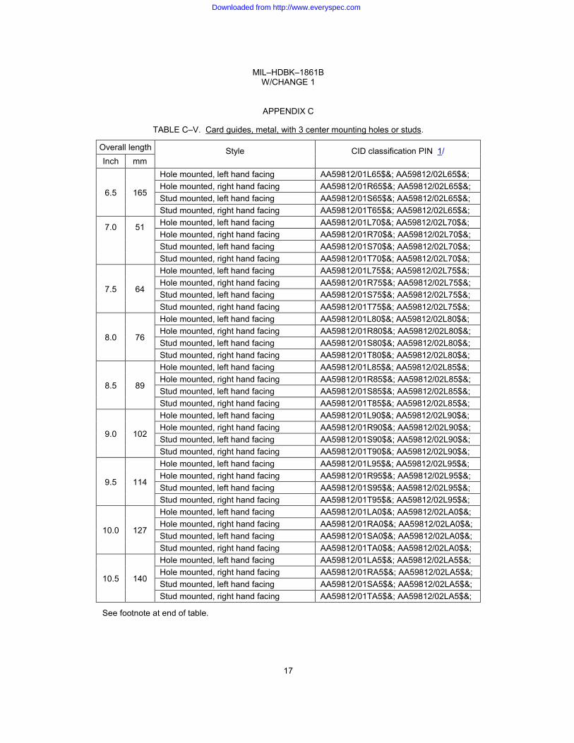
TABLE C–V. Card guides, metal, with 3 center mounting holes or studs.
Overall length Style CID classification PIN 1/ Inch mm
6.5
165
Hole mounted, left hand facing AA59812/01L65$&; AA59812/02L65$&; Hole mounted, right hand facing AA59812/01R65$&; AA59812/02L65$&; Stud mounted, left hand facing AA59812/01S65$&; AA59812/02L65$&; Stud mounted, right hand facing AA59812/01T65$&; AA59812/02L65$&;
7.0 51 Hole mounted, left hand facing AA59812/01L70$&; AA59812/02L70$&; Hole mounted, right hand facing AA59812/01R70$&; AA59812/02L70$&; Stud mounted, left hand facing AA59812/01S70$&; AA59812/02L70$&; Stud mounted, right hand facing AA59812/01T70$&; AA59812/02L70$&;
7.5
64
Hole mounted, left hand facing AA59812/01L75$&; AA59812/02L75$&; Hole mounted, right hand facing AA59812/01R75$&; AA59812/02L75$&; Stud mounted, left hand facing AA59812/01S75$&; AA59812/02L75$&; Stud mounted, right hand facing AA59812/01T75$&; AA59812/02L75$&;
8.0
76
Hole mounted, left hand facing AA59812/01L80$&; AA59812/02L80$&; Hole mounted, right hand facing AA59812/01R80$&; AA59812/02L80$&; Stud mounted, left hand facing AA59812/01S80$&; AA59812/02L80$&; Stud mounted, right hand facing AA59812/01T80$&; AA59812/02L80$&;
8.5
89
Hole mounted, left hand facing AA59812/01L85$&; AA59812/02L85$&; Hole mounted, right hand facing AA59812/01R85$&; AA59812/02L85$&; Stud mounted, left hand facing AA59812/01S85$&; AA59812/02L85$&; Stud mounted, right hand facing AA59812/01T85$&; AA59812/02L85$&;
9.0
102
Hole mounted, left hand facing AA59812/01L90$&; AA59812/02L90$&; Hole mounted, right hand facing AA59812/01R90$&; AA59812/02L90$&; Stud mounted, left hand facing AA59812/01S90$&; AA59812/02L90$&; Stud mounted, right hand facing AA59812/01T90$&; AA59812/02L90$&;
9.5
114
Hole mounted, left hand facing AA59812/01L95$&; AA59812/02L95$&; Hole mounted, right hand facing AA59812/01R95$&; AA59812/02L95$&; Stud mounted, left hand facing AA59812/01S95$&; AA59812/02L95$&; Stud mounted, right hand facing AA59812/01T95$&; AA59812/02L95$&;
10.0
127
Hole mounted, left hand facing AA59812/01LA0$&; AA59812/02LA0$&; Hole mounted, right hand facing AA59812/01RA0$&; AA59812/02LA0$&; Stud mounted, left hand facing AA59812/01SA0$&; AA59812/02LA0$&; Stud mounted, right hand facing AA59812/01TA0$&; AA59812/02LA0$&;
10.5
140
Hole mounted, left hand facing AA59812/01LA5$&; AA59812/02LA5$&; Hole mounted, right hand facing AA59812/01RA5$&; AA59812/02LA5$&; Stud mounted, left hand facing AA59812/01SA5$&; AA59812/02LA5$&; Stud mounted, right hand facing AA59812/01TA5$&; AA59812/02LA5$&;
See footnote at end of table.
17
Downloaded from http://www.everyspec.com

MIL–HDBK–1861B W/CHANGE 1
APPENDIX C
TABLE C–V. Card guides, metal, with 3 center mounting holes or studs – Continued.
Overall length Style CID classification PIN 1/ Inch mm
6.5
64
Hole mounted, left hand facing AA59812/03L65$&; AA59812/04L65$&; Hole mounted, right hand facing AA59812/03R65$&; AA59812/04L65$&; Swag nut mounted, left hand facing AA59812/03S65$&; AA59812/04L65$&; Swag nut mounted, right hand facing AA59812/03T65$&; AA59812/04L65$&;
7.0
178
Hole mounted, left hand facing AA59812/03L70$&; AA59812/04L70$&; Hole mounted, right hand facing AA59812/03R70$&; AA59812/04L70$&; Swag nut mounted, left hand facing AA59812/03S70$&; AA59812/04L70$&; Swag nut mounted, right hand facing AA59812/03T70$&; AA59812/04L70$&;
7.5
191
Hole mounted, left hand facing AA59812/03L75$&; AA59812/04L75$&; Hole mounted, right hand facing AA59812/03R75$&; AA59812/04L75$&; Swag nut mounted, left hand facing AA59812/03S75$&; AA59812/04L75$&; Swag nut mounted, right hand facing AA59812/03T75$&; AA59812/04L75$&;
8.0
203
Hole mounted, left hand facing AA59812/03L80$&; AA59812/04L80$&; Hole mounted, right hand facing AA59812/03R80$&; AA59812/04L80$&; Swag nut mounted, left hand facing AA59812/03S80$&; AA59812/04L80$&; Swag nut mounted, right hand facing AA59812/03T80$&; AA59812/04L80$&;
8.5
216
Hole mounted, left hand facing AA59812/03L85$&; AA59812/04L85$&; Hole mounted, right hand facing AA59812/03R85$&; AA59812/04L85$&; Swag nut mounted, left hand facing AA59812/03S85$&; AA59812/04L85$&; Swag nut mounted, right hand facing AA59812/03T85$&; AA59812/04L85$&;
9.0
229
Hole mounted, left hand facing AA59812/03L90$&; AA59812/04L90$&; Hole mounted, right hand facing AA59812/03R90$&; AA59812/04L90$&; Swag nut mounted, left hand facing AA59812/03S90$&; AA59812/04L90$&; Swag nut mounted, right hand facing AA59812/03T90$&; AA59812/04L90$&;
9.5
241
Hole mounted, left hand facing AA59812/03L95$&; AA59812/04L95$&; Hole mounted, right hand facing AA59812/03R95$&; AA59812/04L95$&; Swag nut mounted, left hand facing AA59812/03S95$&; AA59812/04L95$&; Swag nut mounted, right hand facing AA59812/03T95$&; AA59812/04L95$&;
1/ The dollar sign ($) represents one of the materials available and the ampersands (&) represents the one of the protective finishes available.
18
Downloaded from http://www.everyspec.com

MIL–HDBK–1861B W/CHANGE 1
APPENDIX C
TABLE C–VI. Card guides, metal, slot width .0625 inch (1.59 mm).
Overall length Number of mounting holes
DLA Land and Maritime drawing PIN 1/ Inch mm 1.5 38 2 85033–087, 088, 089, 090, 111, 112, 113, 114 2.0 51 2 85033–091, 092, 093, 094, 115, 116, 117, 118 2.25 57 2 85034–01, 13, 25, 37, 49, 55, 61, 67 2.5 64 2 85033–095, 096, 097, 098, 119, 120, 121, 122 3.0 76 2 84168–001, 002, 005, 006, 3.0 76 3 85033–099, 100, 101, 102, 123, 124, 125, 126 3.25 83 3 85034–03, 15, 27, 39, 51, 57, 63, 69 3.5 89 2 84168–009, 010, 013, 014 3.5 89 3 85033–103, 104, 105, 106, 127, 128, 129, 130 4.0 102 2 84168–017, 018, 021, 022 4.0 102 3 85033–107, 108, 109, 110, 131, 132, 133, 134 4.25 108 4 85034–05, 17, 29, 41 4.5 114 2 84168–025, 026, 029, 030 4.5 114 3 85033–001, 002, 003, 004, 009, 010, 011, 012 5.0 127 3 84168–033, 034, 037, 038 5.25 133 5 85034–07, 19, 31, 43, 53, 59, 65, 71 5.5 140 3 84168–041, 042, 045, 046 6.0 152 3 84168–049, 050, 053, 054 6.0 152 4 85033–017, 018, 019, 023, 024, 025 6.25 159 6 85034–09, 21, 33, 45, 73 7.0 178 3 84168–057, 058, 061, 062 7.0 178 4 85033–211, 212, 217, 218 7.5 191 3 84168–065, 066, 69, 70 8.0 203 5 85033–199, 200 8.25 210 8 85034–11, 23, 35, 47 8.5 216 3 84168–073, 074, 077, 078 10.0 254 6 85033–205, 206
1/ DESC drawing 85033 contains provisions for three finish options, optional housing index pins, optional hex head drive indexing, and whether the card guide comes assembled or in a disassembled kit form.
19
Downloaded from http://www.everyspec.com

MIL–HDBK–1861B W/CHANGE 1
APPENDIX C
TABLE C–VII. Card guides, metal, slot width .0937 inch (2.38 mm).
Overall length Number of mounting holes
DLA Land and Maritime drawing PIN 1/ Inch mm
1.5 38 2 85033–135, 136, 137, 138, 159, 160, 161, 162
2.0 51 2 85033–139, 140, 141, 142, 163, 164, 165, 166
2.5 57 2 85033–143, 144, 145, 146, 167, 168, 169, 170
3.0 76 2 84168–003, 004, 007, 008
3.0 76 3 85033–147, 148, 149, 150, 171, 172, 173, 174
3.25 83 3 85034–04, 16, 28, 40, 52, 58, 64, 70
3.5 89 2 84168–011, 012, 015, 016
3.5 89 3 85033–151, 152, 153, 154, 175, 176, 177, 178
4.0 102 2 84168–019, 020, 023, 024
4.0 102 3 85033–155, 156, 157, 158, 179, 180, 181, 182
4.25 108 4 85034–06, 18, 30, 42
4.5 114 2 84168–027, 028, 031, 032
4.5 114 3 85033–005, 006, 007, 008, 013, 014, 015, 016
5.0 127 3 84168–035, 036, 039, 040
5.25 133 5 85034–08, 20, 32, 44, 54, 60, 66, 72
5.5 140 3 84168–043, 044, 047, 048
6.0 152 3 84168–051, 052, 055, 056
6.0 152 4 85033–020, 021, 022, 026, 027, 028
6.25 159 6 85034–10, 22, 34, 46, 74
7.0 178 3 84168–059, 060, 063, 064
7.0 178 4 85033–213, 214, 219, 220
7.5 191 3 84168–067, 068, 071, 072
8.0 203 5 85033–201, 202
8.25 210 8 85034–12, 24, 36, 48
8.5 216 3 84168–075, 076, 079, 080
10.0 254 6 85033–207, 208
1/ DESC drawing 85033 contains provisions for three finish options, optional housing index pins, optional hex head drive indexing, and whether the card guide comes assembled or in a disassembled kit form.
20
Downloaded from http://www.everyspec.com
MIL–HDBK–1861B W/CHANGE 1
APPENDIX C
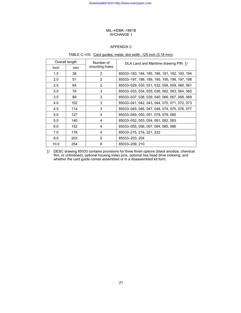
TABLE C–VIII. Card guides, metal, slot width .125 inch (3.18 mm).
Overall length Number of mounting holes
DLA Land and Maritime drawing PIN 1/ Inch mm
1.5 38 2 85033–183, 184, 185, 186, 191, 192, 193, 194 2.0 51 2 85033–187, 188, 189, 190, 195, 196, 197, 198 2.5 64 2 85033–029, 030, 031, 032, 058, 059, 060, 061 3.0 76 3 85033–033, 034, 035, 036, 062, 063, 064, 065 3.5 89 3 85033–037, 038, 039, 040, 066, 067, 068, 069 4.0 102 3 85033–041, 042, 043, 044, 070, 071, 072, 073 4.5 114 3 85033–045, 046, 047, 048, 074, 075, 076, 077 5.0 127 4 85033–049, 050, 051, 078, 079, 080 5.5 140 4 85033–052, 053, 054, 081, 082, 083 6.0 152 4 85033–055, 056, 057, 084, 085, 086 7.0 178 4 85033–215, 216, 221, 222 8.0 203 5 85033–203, 204
10.0 254 6 85033–209, 210
1/ DESC drawing 85033 contains provisions for three finish options (black anodize, chemical film, or unfinished), optional housing index pins, optional hex head drive indexing, and whether the card guide comes assembled or in a disassembled kit form.
21
Downloaded from http://www.everyspec.com
MIL–HDBK–1861B W/CHANGE 1
APPENDIX C
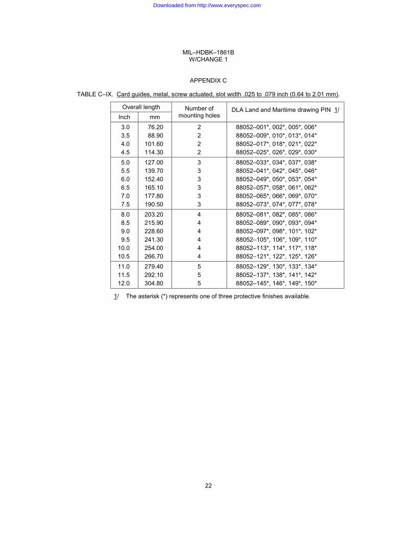
TABLE C–IX. Card guides, metal, screw actuated, slot width .025 to .079 inch (0.64 to 2.01 mm).
Overall length Number of mounting holes
DLA Land and Maritime drawing PIN 1/ Inch mm
3.0 3.5 4.0 4.5
76.20 88.90
101.60 114.30
2 2 2 2
88052–001*, 002*, 005*, 006* 88052–009*, 010*, 013*, 014* 88052–017*, 018*, 021*, 022* 88052–025*, 026*, 029*, 030*
5.0 5.5 6.0 6.5 7.0 7.5
127.00 139.70 152.40 165.10 177.80 190.50
3 3 3 3 3 3
88052–033*, 034*, 037*, 038* 88052–041*, 042*, 045*, 046* 88052–049*, 050*, 053*, 054* 88052–057*, 058*, 061*, 062* 88052–065*, 066*, 069*, 070* 88052–073*, 074*, 077*, 078*
8.0 8.5 9.0 9.5
10.0 10.5
203.20 215.90 228.60 241.30 254.00 266.70
4 4 4 4 4 4
88052–081*, 082*, 085*, 086* 88052–089*, 090*, 093*, 094* 88052–097*, 098*, 101*, 102* 88052–105*, 106*, 109*, 110* 88052–113*, 114*, 117*, 118* 88052–121*, 122*, 125*, 126*
11.0 11.5 12.0
279.40 292.10 304.80
5 5 5
88052–129*, 130*, 133*, 134* 88052–137*, 138*, 141*, 142* 88052–145*, 146*, 149*, 150*
1/ The asterisk (*) represents one of three protective finishes available.
22
Downloaded from http://www.everyspec.com
MIL–HDBK–1861B W/CHANGE 1
APPENDIX C
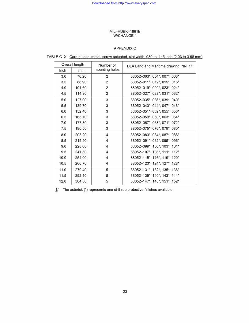
TABLE C–X. Card guides, metal, screw actuated, slot width .080 to .145 inch (2.03 to 3.68 mm).
Overall length Number of mounting holes
DLA Land and Maritime drawing PIN 1/ Inch mm
3.0 3.5 4.0 4.5
76.20 88.90
101.60 114.30
2 2 2 2
88052–003*, 004*, 007*, 008* 88052–011*, 012*, 015*, 016* 88052–019*, 020*, 023*, 024* 88052–027*, 028*, 031*, 032*
5.0 5.5 6.0 6.5 7.0 7.5
127.00 139.70 152.40 165.10 177.80 190.50
3 3 3 3 3 3
88052–035*, 036*, 039*, 040* 88052–043*, 044*, 047*, 048* 88052–051*, 052*, 055*, 056* 88052–059*, 060*, 063*, 064* 88052–067*, 068*, 071*, 072* 88052–075*, 076*, 079*, 080*
8.0 8.5 9.0 9.5
10.0 10.5
203.20 215.90 228.60 241.30 254.00 266.70
4 4 4 4 4 4
88052–083*, 084*, 087*, 088* 88052–091*, 082*, 095*, 096* 88052–099*, 100*, 103*, 104* 88052–107*, 108*, 111*, 112* 88052–115*, 116*, 119*, 120* 88052–123*, 124*, 127*, 128*
11.0 11.5 12.0
279.40 292.10 304.80
5 5 5
88052–131*, 132*, 135*, 136* 88052–139*, 140*, 143*, 144* 88052–147*, 148*, 151*, 152*
1/ The asterisk (*) represents one of three protective finishes available.
23
Downloaded from http://www.everyspec.com

MIL–HDBK–1861B W/CHANGE 1
APPENDIX C
TABLE C–XI. Card guides, metal, lever actuated, slot width .211 inch (5.36 mm) + PWB thickness.
Overall length Number of mounting holes
DLA Land and Maritime drawing PIN Inch mm
3.0 3.5 4.0 4.5
76.20 88.90
101.60 114.30
2 2 2 2
86092–01, 02, 03, 04 86092–05, 06, 07, 08 86092–09, 10, 11, 12 86092–13, 14, 15, 16
5.0 5.5 6.0 7.0 7.5
127.00 139.70 152.40 177.80 190.50
3 3 3 3 3
86092–17, 18, 19, 20 86092–21, 22, 23, 24 86092–25, 26, 27, 28 86092–29, 30, 31, 32 86092–33, 34, 35, 36
8.0 203.20 4 86092–37, 38, 39, 40
TABLE C–XII. Card guides, plastic, pylon mounted, shallow slot, slot width .078 inch (1.98 mm).
Overall length Number of snap pylons
DLA Land and Maritime drawing PIN Inch mm
2.5 3.0 3.5 4.0 4.5 5.0 5.5 6.0 6.5 7.0 7.5 8.0
63.50 76.20 88.90
101.60 114.30 127.00 139.70 152.40 165.10 177.80 190.50 203.20
2 2 2 2 2 2 2 2 2 2 2 2
84006–01 84006–02 84006–03 84006–04 84006–05 84006–06 84006–07 84006–08 84006–09 84006–10 84006–11 84006–12
8.5 9.0 9.5
10.0 10.5 11.0 11.5 12.0 12.5 13.0 13.5 14.0
215.90 228.60 241.30 254.00 266.70 279.40 292.10 304.80 317.50 330.20 342.90 355.60
3 3 3 3 3 3 3 3 3 3 3 3
84006–13 84006–14 84006–15 84006–16 84006–17 84006–18 84006–19 84006–20 84006–21 84006–22 84006–23 84006–24
24
Downloaded from http://www.everyspec.com
MIL–HDBK–1861B W/CHANGE 1
APPENDIX C
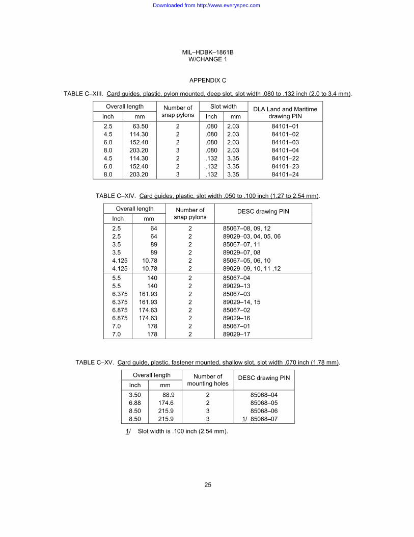
TABLE C–XIII. Card guides, plastic, pylon mounted, deep slot, slot width .080 to .132 inch (2.0 to 3.4 mm).
Overall length Number of snap pylons
Slot width DLA Land and Maritime drawing PIN Inch mm Inch mm
2.5 4.5 6.0 8.0 4.5 6.0 8.0
63.50 114.30 152.40 203.20 114.30 152.40 203.20
2 2 2 3 2 2 3
.080
.080
.080
.080
.132
.132
.132
2.03 2.03 2.03 2.03 3.35 3.35 3.35
84101–01 84101–02 84101–03 84101–04 84101–22 84101–23 84101–24
TABLE C–XIV. Card guides, plastic, slot width .050 to .100 inch (1.27 to 2.54 mm).
Overall length Number of snap pylons
DESC drawing PIN Inch mm
2.5 2.5 3.5 3.5 4.125 4.125
64 64 89 89
10.78 10.78
2 2 2 2 2 2
85067–08, 09, 12 89029–03, 04, 05, 06 85067–07, 11 89029–07, 08 85067–05, 06, 10 89029–09, 10, 11 ,12
5.5 5.5 6.375 6.375 6.875 6.875 7.0 7.0
140 140
161.93 161.93 174.63 174.63
178 178
2 2 2 2 2 2 2 2
85067–04 89029–13 85067–03 89029–14, 15 85067–02 89029–16 85067–01 89029–17
TABLE C–XV. Card guide, plastic, fastener mounted, shallow slot, slot width .070 inch (1.78 mm).
Overall length Number of mounting holes
DESC drawing PIN Inch mm
3.50 6.88 8.50 8.50
88.9 174.6 215.9 215.9
2 2 3 3
85068–04 85068–05 85068–06
1/ 85068–07
1/ Slot width is .100 inch (2.54 mm).
25
Downloaded from http://www.everyspec.com

MIL–HDBK–1861B W/CHANGE 1
APPENDIX C
This page intentionally left blank.
26
Downloaded from http://www.everyspec.com
MIL–HDBK–1861B W/CHANGE 1
APPENDIX D
CARD HOLDERS
D.1. SCOPE
D.1.1 Scope. This appendix covers commercial item descriptions and drawings used for card holders. The parts described by these commercial item descriptions and drawings and are used to supplement Military specifications.
D.2. WEDGE STYLE CARD HOLDERS
D.2.1 Three body wedge card holders. Three body wedge circuit card assembly retainers are found in tables D–I through D–IX.
D.2.2 Five body wedge card holders. Five body wedge circuit card assembly retainers are found in tables D–X through D–XII.
D.2.3 Seven body wedge card holders. Seven body wedge circuit card assembly card holders are found in tables D–X through D–XII.
27
Downloaded from http://www.everyspec.com
MIL–HDBK–1861B W/CHANGE 1
APPENDIX D
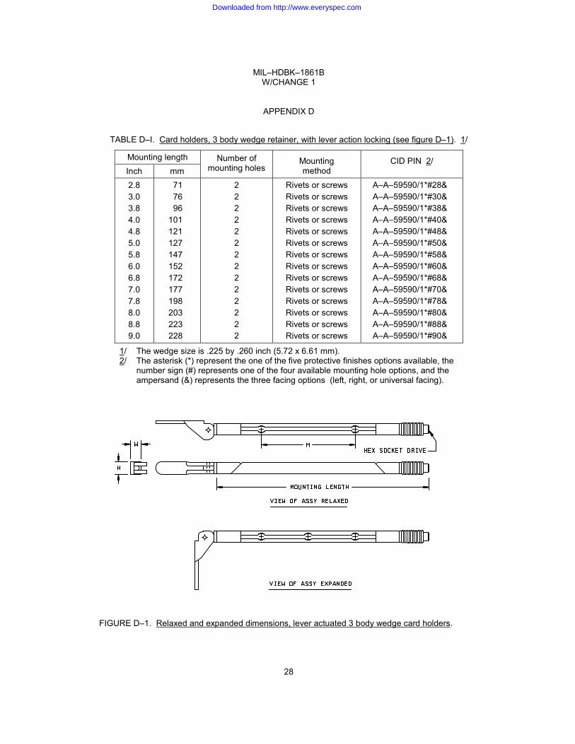
TABLE D–I. Card holders, 3 body wedge retainer, with lever action locking (see figure D–1). 1/
Mounting length Number of mounting holes
Mounting method
CID PIN 2/ Inch mm
2.8 3.0 3.8 4.0 4.8 5.0 5.8 6.0 6.8 7.0 7.8 8.0 8.8 9.0
71 76 96 101 121 127 147 152 172 177 198 203 223 228
2 2 2 2 2 2 2 2 2 2 2 2 2 2
Rivets or screws Rivets or screws Rivets or screws Rivets or screws Rivets or screws Rivets or screws Rivets or screws Rivets or screws Rivets or screws Rivets or screws Rivets or screws Rivets or screws Rivets or screws Rivets or screws
A–A–59590/1*#28& A–A–59590/1*#30& A–A–59590/1*#38& A–A–59590/1*#40& A–A–59590/1*#48& A–A–59590/1*#50& A–A–59590/1*#58& A–A–59590/1*#60& A–A–59590/1*#68& A–A–59590/1*#70& A–A–59590/1*#78& A–A–59590/1*#80& A–A–59590/1*#88& A–A–59590/1*#90&
1/ The wedge size is .225 by .260 inch (5.72 x 6.61 mm). 2/ The asterisk (*) represent the one of the five protective finishes options available, the
number sign (#) represents one of the four available mounting hole options, and the ampersand (&) represents the three facing options (left, right, or universal facing).
FIGURE D–1. Relaxed and expanded dimensions, lever actuated 3 body wedge card holders.
28
Downloaded from http://www.everyspec.com

MIL–HDBK–1861B W/CHANGE 1
APPENDIX D
TABLE D–II. Card holders, 3 body wedge retainer, with ejection action (see figure D–2). 1/
Mounting length Mounting method
CID PIN 2/ 3/ Inch mm
2.8 3.2 3.5 3.8 4.0 4.8 5.8 6.4
71 89 76 96 101 121 147 152
Rivets or screws Rivets or screws Rivets or screws Rivets or screws Rivets or screws Rivets or screws Rivets or screws Rivets or screws
A–A–59590/2*#28&, A–A–59590/25*#28& A–A–59590/25*#32& A–A–59590/2*#35& A–A–59590/2*#38&, A–A–59590/25*#38& A–A–59590/2*#40& A–A–59590/2*#48&, A–A–59590/25*#48& A–A–59590/2*#58& A–A–59590/2*#64&, A–A–59590/25*#64&
1/ The wedge size is .225 by .260 inch (5.72 x 6.61 mm). 2/ The asterisk (*) represent the five protective finish options, the number sign (#) represents the
four mounting hole options, and the ampersand (&) represents the three hardware options (lockwasher and flat washer, screw self–locking element, and a combination or both previous options).
3/ A–A–59590/25 covers card holders with visual lock indication.
FIGURE D–2. Relaxed and expanded dimensions, ejection action 3 body wedge card holders.
29
Downloaded from http://www.everyspec.com
MIL–HDBK–1861B W/CHANGE 1
APPENDIX D
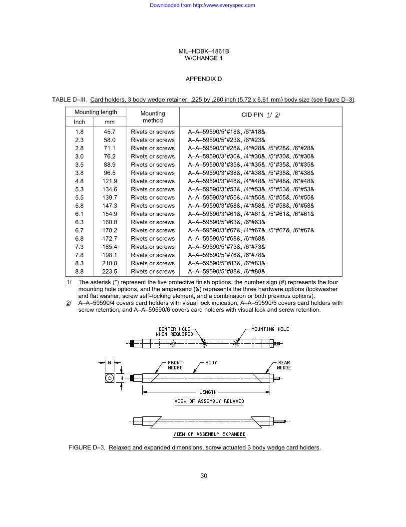
TABLE D–III. Card holders, 3 body wedge retainer, .225 by .260 inch (5.72 x 6.61 mm) body size (see figure D–3).
Mounting length Mounting method
CID PIN 1/ 2/ Inch mm
1.8 2.3 2.8 3.0 3.5 3.8 4.8 5.3 5.5 5.8 6.1 6.3 6.7 6.8 7.3 7.8 8.3 8.8
45.7 58.0 71.1 76.2 88.9 96.5
121.9 134.6 139.7 147.3 154.9 160.0 170.2 172.7 185.4 198.1 210.8 223.5
Rivets or screws Rivets or screws Rivets or screws Rivets or screws Rivets or screws Rivets or screws Rivets or screws Rivets or screws Rivets or screws Rivets or screws Rivets or screws Rivets or screws Rivets or screws Rivets or screws Rivets or screws Rivets or screws Rivets or screws Rivets or screws
A–A–59590/5*#18&, /6*#18& A–A–59590/5*#23&, /6*#23& A–A–59590/3*#28&, /4*#28&, /5*#28&, /6*#28& A–A–59590/3*#30&, /4*#30&, /5*#30&, /6*#30& A–A–59590/3*#35&, /4*#35&, /5*#35&, /6*#35& A–A–59590/3*#38&, /4*#38&, /5*#38&, /6*#38& A–A–59590/3*#48&, /4*#48&, /5*#48&, /6*#48& A–A–59590/3*#53&, /4*#53&, /5*#53&, /6*#53& A–A–59590/3*#55&, /4*#55&, /5*#55&, /6*#55& A–A–59590/3*#58&, /4*#58&, /5*#58&, /6*#58& A–A–59590/3*#61&, /4*#61&, /5*#61&, /6*#61& A–A–59590/5*#63&, /6*#63& A–A–59590/3*#67&, /4*#67&, /5*#67&, /6*#67& A–A–59590/5*#68&, /6*#68& A–A–59590/5*#73&, /6*#73& A–A–59590/5*#78&, /6*#78& A–A–59590/5*#83&, /6*#83& A–A–59590/5*#88&, /6*#88&
1/ The asterisk (*) represent the five protective finish options, the number sign (#) represents the four mounting hole options, and the ampersand (&) represents the three hardware options (lockwasher and flat washer, screw self–locking element, and a combination or both previous options).
2/ A–A–59590/4 covers card holders with visual lock indication, A–A–59590/5 covers card holders with screw retention, and A–A–59590/6 covers card holders with visual lock and screw retention.
FIGURE D–3. Relaxed and expanded dimensions, screw actuated 3 body wedge card holders.
30
Downloaded from http://www.everyspec.com

MIL–HDBK–1861B W/CHANGE 1
APPENDIX D
TABLE D–IV. Card holders, 3 body wedge retainer, .220 by .220 inch (5.59 x 5.9 mm) body size.
Mounting length Mounting method
CID PIN 1/ 2/ Inch mm
1.8 2.3 2.8 3.0 3.3 3.5 3.8 4.3 4.8
45.7 58.4 71.1 76.2 83.8 88.9 96.5
109.2 121.9
Rivets or screws Rivets or screws Rivets or screws Rivets or screws Rivets or screws Rivets or screws Rivets or screws Rivets or screws Rivets or screws
A–A–59590/7*#18&, /8*#18&, /9*#18&, /10*#18& A–A–59590/7*#23&, /8*#23&, /9*#23&, /10*#23& A–A–59590/7*#28&, /8*#28&, /9*#28&, /10*#28& A–A–59590/7*#30&, /8*#30&, /9*#30&, /10*#30& A–A–59590/7*#33&, /8*#33&, /9*#33&, /10*#33& A–A–59590/7*#35&, /8*#35&, /9*#35&, /10*#35& A–A–59590/7*#38&, /8*#38&, /9*#38&, /10*#38& A–A–59590/7*#43&, /8*#43&, /9*#43&, /10*#43& A–A–59590/7*#48&, /8*#48&, /9*#48&, /10*#48&
5.3 5.8 6.3 6.8 7.3 7.8 8.3 8.8
134.6 147.3 160.0 172.7 185.4 198.1 210.8 223.5
Rivets or screws Rivets or screws Rivets or screws Rivets or screws Rivets or screws Rivets or screws Rivets or screws Rivets or screws
A–A–59590/7*#53&, /8*#53&, /9*#53&, /10*#53& A–A–59590/7*#55&, /8*#55&, /9*#55&, /10*#55& A–A–59590/7*#63&, /8*#63&, /9*#63&, /10*#63& A–A–59590/7*#68&, /8*#68&, /9*#68&, /10*#68& A–A–59590/7*#73&, /8*#73&, /9*#73&, /10*#73& A–A–59590/7*#78&, /8*#78&, /9*#78&, /10*#78& A–A–59590/7*#83&, /8*#83&, /9*#83&, /10*#83& A–A–59590/7*#88&, /8*#88&, /9*#88&, /10*#88&
1/ The asterisk (*) represent the three protective finish options, the number sign (#) represents the seven mounting hole options, and the ampersand (&) represents the three hardware options (lockwasher and flat washer, screw self–locking element, and a combination or both previous options).
2/ A–A–59590/8 covers card holders with visual lock indication, A–A–59590/9 covers card holders with screw retention, and A–A–59590/10 covers card holders with visual lock and screw retention.
31
Downloaded from http://www.everyspec.com
MIL–HDBK–1861B W/CHANGE 1
APPENDIX D
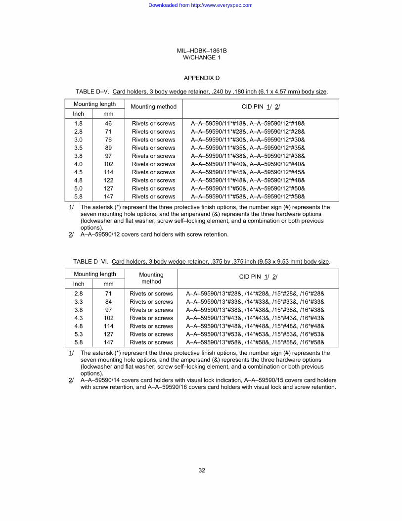
TABLE D–V. Card holders, 3 body wedge retainer, .240 by .180 inch (6.1 x 4.57 mm) body size.
Mounting length Mounting method CID PIN 1/ 2/ Inch mm
1.8 2.8 3.0 3.5 3.8 4.0 4.5 4.8 5.0 5.8
46 71 76 89 97
102 114 122 127 147
Rivets or screws Rivets or screws Rivets or screws Rivets or screws Rivets or screws Rivets or screws Rivets or screws Rivets or screws Rivets or screws Rivets or screws
A–A–59590/11*#18&, A–A–59590/12*#18& A–A–59590/11*#28&, A–A–59590/12*#28& A–A–59590/11*#30&, A–A–59590/12*#30& A–A–59590/11*#35&, A–A–59590/12*#35& A–A–59590/11*#38&, A–A–59590/12*#38& A–A–59590/11*#40&, A–A–59590/12*#40& A–A–59590/11*#45&, A–A–59590/12*#45& A–A–59590/11*#48&, A–A–59590/12*#48& A–A–59590/11*#50&, A–A–59590/12*#50& A–A–59590/11*#58&, A–A–59590/12*#58&
1/ The asterisk (*) represent the three protective finish options, the number sign (#) represents the seven mounting hole options, and the ampersand (&) represents the three hardware options (lockwasher and flat washer, screw self–locking element, and a combination or both previous options).
2/ A–A–59590/12 covers card holders with screw retention.
TABLE D–VI. Card holders, 3 body wedge retainer, .375 by .375 inch (9.53 x 9.53 mm) body size.
Mounting length Mounting method
CID PIN 1/ 2/ Inch mm
2.8 3.3 3.8 4.3 4.8 5.3 5.8
71 84 97
102 114 127 147
Rivets or screws Rivets or screws Rivets or screws Rivets or screws Rivets or screws Rivets or screws Rivets or screws
A–A–59590/13*#28&, /14*#28&, /15*#28&, /16*#28& A–A–59590/13*#33&, /14*#33&, /15*#33&, /16*#33& A–A–59590/13*#38&, /14*#38&, /15*#38&, /16*#38& A–A–59590/13*#43&, /14*#43&, /15*#43&, /16*#43& A–A–59590/13*#48&, /14*#48&, /15*#48&, /16*#48& A–A–59590/13*#53&, /14*#53&, /15*#53&, /16*#53& A–A–59590/13*#58&, /14*#58&, /15*#58&, /16*#58&
1/ The asterisk (*) represent the three protective finish options, the number sign (#) represents the seven mounting hole options, and the ampersand (&) represents the three hardware options (lockwasher and flat washer, screw self–locking element, and a combination or both previous options).
2/ A–A–59590/14 covers card holders with visual lock indication, A–A–59590/15 covers card holders with screw retention, and A–A–59590/16 covers card holders with visual lock and screw retention.
32
Downloaded from http://www.everyspec.com
MIL–HDBK–1861B W/CHANGE 1
APPENDIX D
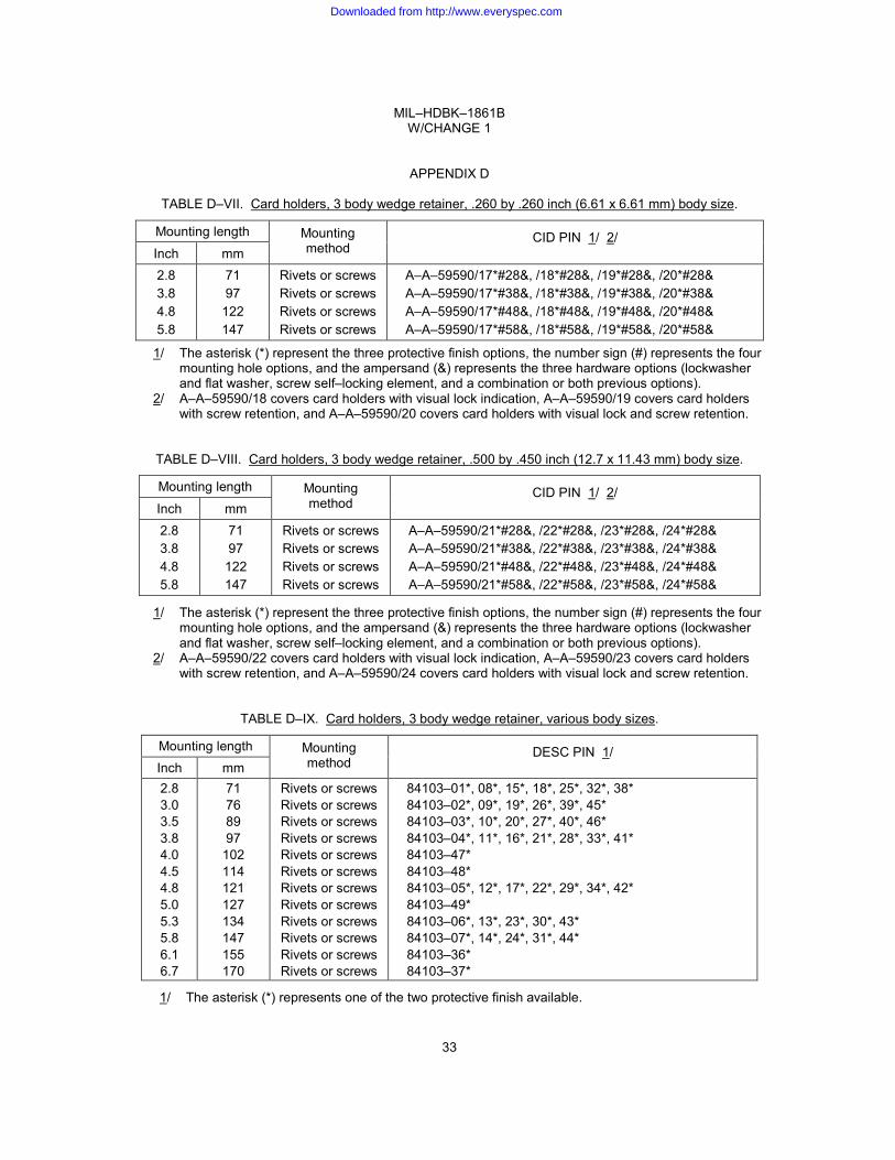
TABLE D–VII. Card holders, 3 body wedge retainer, .260 by .260 inch (6.61 x 6.61 mm) body size.
Mounting length Mounting method
CID PIN 1/ 2/ Inch mm
2.8 3.8 4.8 5.8
71 97
122 147
Rivets or screws Rivets or screws Rivets or screws Rivets or screws
A–A–59590/17*#28&, /18*#28&, /19*#28&, /20*#28& A–A–59590/17*#38&, /18*#38&, /19*#38&, /20*#38& A–A–59590/17*#48&, /18*#48&, /19*#48&, /20*#48& A–A–59590/17*#58&, /18*#58&, /19*#58&, /20*#58&
1/ The asterisk (*) represent the three protective finish options, the number sign (#) represents the four mounting hole options, and the ampersand (&) represents the three hardware options (lockwasher and flat washer, screw self–locking element, and a combination or both previous options).
2/ A–A–59590/18 covers card holders with visual lock indication, A–A–59590/19 covers card holders with screw retention, and A–A–59590/20 covers card holders with visual lock and screw retention.
TABLE D–VIII. Card holders, 3 body wedge retainer, .500 by .450 inch (12.7 x 11.43 mm) body size.
Mounting length Mounting method
CID PIN 1/ 2/ Inch mm
2.8 3.8 4.8 5.8
71 97
122 147
Rivets or screws Rivets or screws Rivets or screws Rivets or screws
A–A–59590/21*#28&, /22*#28&, /23*#28&, /24*#28& A–A–59590/21*#38&, /22*#38&, /23*#38&, /24*#38& A–A–59590/21*#48&, /22*#48&, /23*#48&, /24*#48& A–A–59590/21*#58&, /22*#58&, /23*#58&, /24*#58&
1/ The asterisk (*) represent the three protective finish options, the number sign (#) represents the four mounting hole options, and the ampersand (&) represents the three hardware options (lockwasher and flat washer, screw self–locking element, and a combination or both previous options).
2/ A–A–59590/22 covers card holders with visual lock indication, A–A–59590/23 covers card holders with screw retention, and A–A–59590/24 covers card holders with visual lock and screw retention.
TABLE D–IX. Card holders, 3 body wedge retainer, various body sizes.
Mounting length Mounting method
DESC PIN 1/ Inch mm
2.8 3.0 3.5 3.8 4.0 4.5 4.8 5.0 5.3 5.8 6.1 6.7
71 76 89 97
102 114 121 127 134 147 155 170
Rivets or screws Rivets or screws Rivets or screws Rivets or screws Rivets or screws Rivets or screws Rivets or screws Rivets or screws Rivets or screws Rivets or screws Rivets or screws Rivets or screws
84103–01*, 08*, 15*, 18*, 25*, 32*, 38* 84103–02*, 09*, 19*, 26*, 39*, 45* 84103–03*, 10*, 20*, 27*, 40*, 46* 84103–04*, 11*, 16*, 21*, 28*, 33*, 41* 84103–47* 84103–48* 84103–05*, 12*, 17*, 22*, 29*, 34*, 42* 84103–49* 84103–06*, 13*, 23*, 30*, 43* 84103–07*, 14*, 24*, 31*, 44* 84103–36* 84103–37*
1/ The asterisk (*) represents one of the two protective finish available.
33
Downloaded from http://www.everyspec.com
MIL–HDBK–1861B W/CHANGE 1
APPENDIX D
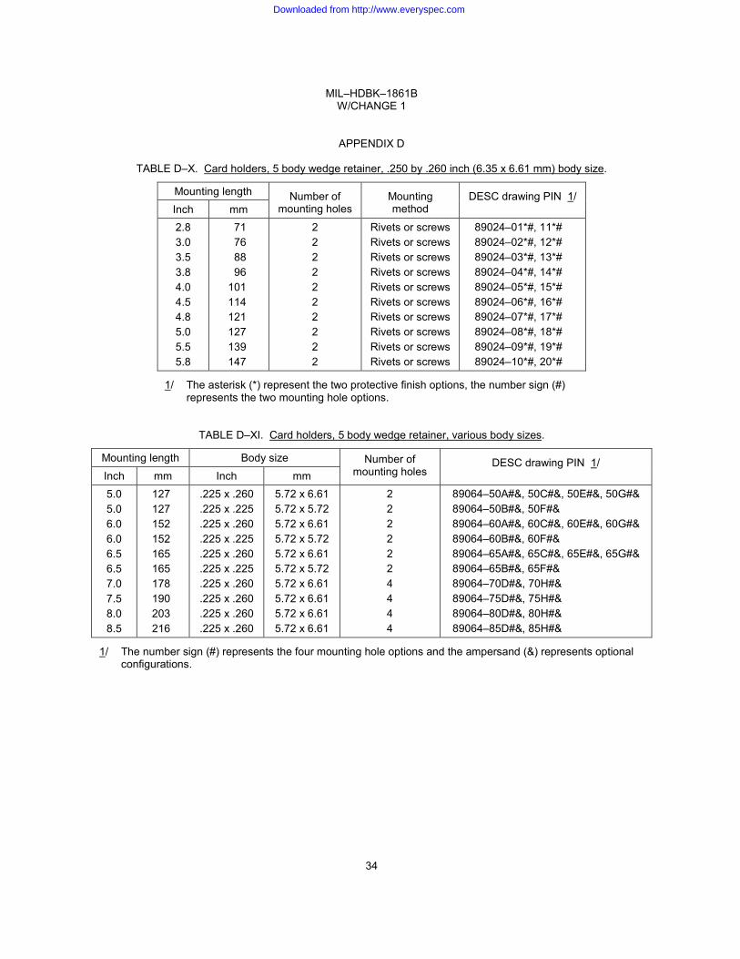
TABLE D–X. Card holders, 5 body wedge retainer, .250 by .260 inch (6.35 x 6.61 mm) body size.
Mounting length Number of mounting holes
Mounting method
DESC drawing PIN 1/ Inch mm
2.8 3.0 3.5 3.8 4.0 4.5 4.8 5.0 5.5 5.8
71 76 88 96 101 114 121 127 139 147
2 2 2 2 2 2 2 2 2 2
Rivets or screws Rivets or screws Rivets or screws Rivets or screws Rivets or screws Rivets or screws Rivets or screws Rivets or screws Rivets or screws Rivets or screws
89024–01*#, 11*# 89024–02*#, 12*# 89024–03*#, 13*# 89024–04*#, 14*# 89024–05*#, 15*# 89024–06*#, 16*# 89024–07*#, 17*# 89024–08*#, 18*# 89024–09*#, 19*# 89024–10*#, 20*#
1/ The asterisk (*) represent the two protective finish options, the number sign (#) represents the two mounting hole options.
TABLE D–XI. Card holders, 5 body wedge retainer, various body sizes.
Mounting length Body size Number of mounting holes
DESC drawing PIN 1/ Inch mm Inch mm
5.0 5.0 6.0 6.0 6.5 6.5 7.0 7.5 8.0 8.5
127 127 152 152 165 165 178 190 203 216
.225 x .260
.225 x .225
.225 x .260
.225 x .225
.225 x .260
.225 x .225
.225 x .260
.225 x .260
.225 x .260
.225 x .260
5.72 x 6.61 5.72 x 5.72 5.72 x 6.61 5.72 x 5.72 5.72 x 6.61 5.72 x 5.72 5.72 x 6.61 5.72 x 6.61 5.72 x 6.61 5.72 x 6.61
2 2 2 2 2 2 4 4 4 4
89064–50A#&, 50C#&, 50E#&, 50G#& 89064–50B#&, 50F#& 89064–60A#&, 60C#&, 60E#&, 60G#& 89064–60B#&, 60F#& 89064–65A#&, 65C#&, 65E#&, 65G#& 89064–65B#&, 65F#& 89064–70D#&, 70H#& 89064–75D#&, 75H#& 89064–80D#&, 80H#& 89064–85D#&, 85H#&
1/ The number sign (#) represents the four mounting hole options and the ampersand (&) represents optional configurations.
34
Downloaded from http://www.everyspec.com
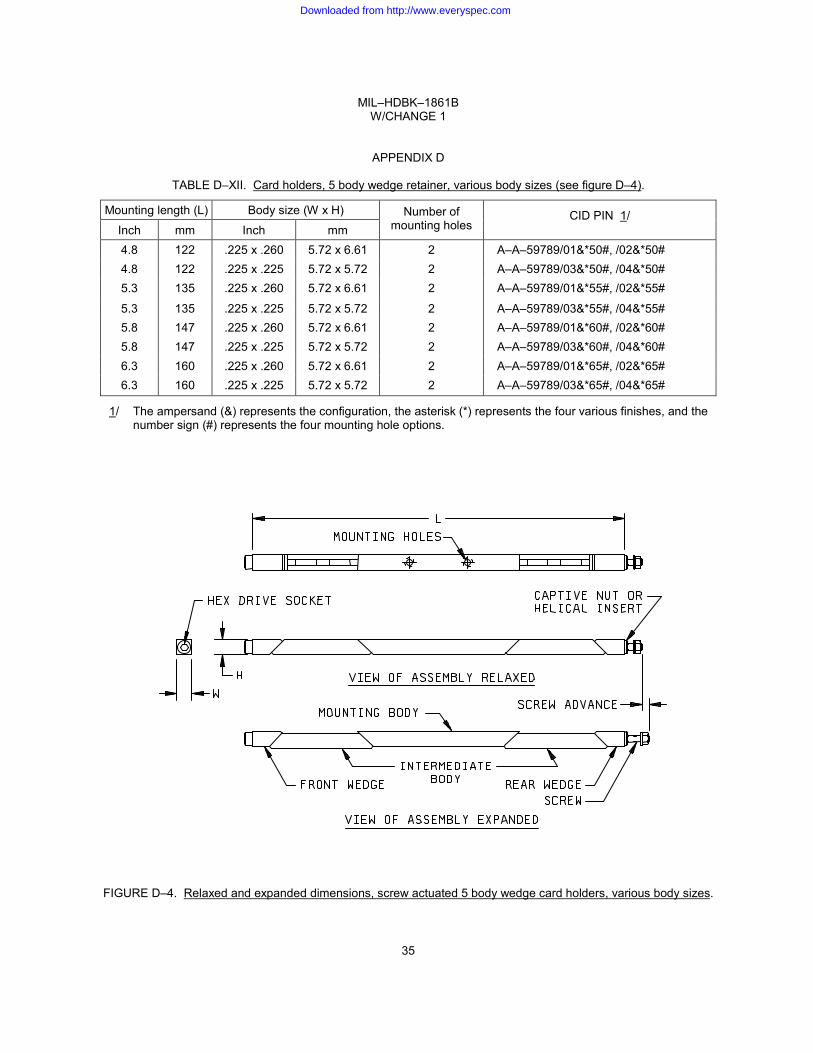
MIL–HDBK–1861B W/CHANGE 1
APPENDIX D
TABLE D–XII. Card holders, 5 body wedge retainer, various body sizes (see figure D–4).
Mounting length (L) Body size (W x H) Number of mounting holes
CID PIN 1/ Inch mm Inch mm
4.8 122 .225 x .260 5.72 x 6.61 2 A–A–59789/01&*50#, /02&*50# 4.8 122 .225 x .225 5.72 x 5.72 2 A–A–59789/03&*50#, /04&*50# 5.3 135 .225 x .260 5.72 x 6.61 2 A–A–59789/01&*55#, /02&*55#
5.3 135 .225 x .225 5.72 x 5.72 2 A–A–59789/03&*55#, /04&*55# 5.8 147 .225 x .260 5.72 x 6.61 2 A–A–59789/01&*60#, /02&*60# 5.8 147 .225 x .225 5.72 x 5.72 2 A–A–59789/03&*60#, /04&*60# 6.3 160 .225 x .260 5.72 x 6.61 2 A–A–59789/01&*65#, /02&*65# 6.3 160 .225 x .225 5.72 x 5.72 2 A–A–59789/03&*65#, /04&*65#
1/ The ampersand (&) represents the configuration, the asterisk (*) represents the four various finishes, and the number sign (#) represents the four mounting hole options.
FIGURE D–4. Relaxed and expanded dimensions, screw actuated 5 body wedge card holders, various body sizes.
35
Downloaded from http://www.everyspec.com

MIL–HDBK–1861B W/CHANGE 1
APPENDIX D
TABLE D–XIII. Card holders, 7 body wedge retainer, .225 x .225 inch (5.72 x 5.72 mm) body size.
Mounting length (L) Body size (W x H) Number of mounting holes
CID PIN 1/ Inch mm Inch mm
4.8 122 .225 x .225 5.72 x 5.72 2 or 3 A–A–59950/01&*48#, /02&*48# 5.3 135 .225 x .225 5.72 x 5.72 2 or 3 A–A–59950/01&*53#, /02&*53# 5.8 147 .225 x .225 5.72 x 5.72 2 or 3 A–A–59950/01&*58#, /02&*58# 6.3 160 .225 x .225 5.72 x 5.72 2 or 3 A–A–59950/01&*63#, /02&*63# 6.8 173 .225 x .225 5.72 x 5.72 2 or 3 A–A–59950/01&*68#, /04&*68# 7.3 185 .225 x .225 5.72 x 5.72 2 or 3 A–A–59950/01&*73#, /02&*73# 7.8 198 .225 x .225 5.72 x 5.72 2 or 3 A–A–59950/01&*78#, /02&*78#
1/ The ampersand (&) represents the configuration, the asterisk (*) represents the four various finishes, and the number sign (#) represents the four mounting hole options.
TABLE D–XIV. Card holders, 7 body wedge retainer, .250 x .260 inch (6.35 x 6.61 mm) body size.
Mounting length (L) Body size (W x H) Number of mounting holes
CID PIN 1/ Inch mm Inch mm
4.8 122 .250 x .260 6.35 x 6.61 2 or 3 A–A–59950/03&*48#, /04&*48# 5.3 135 .250 x .260 6.35 x 6.61 2 or 3 A–A–59950/03&*53#, /04&*53#
5.8 147 .250 x .260 6.35 x 6.61 2 or 3 A–A–59950/03&*580#, /04&*58# 6.3 160 .250 x .260 6.35 x 6.61 2 or 3 A–A–59950/03&*63#, /04&*63# 6.8 173 .250 x .260 6.35 x 6.61 2 or 3 A–A–59950/03&*68#, /04&*68# 7.3 185 .250 x .260 6.35 x 6.61 2 or 3 A–A–59950/03&*73#, /04&*73# 7.8 198 .250 x .260 6.35 x 6.61 2 or 3 A–A–59950/03&*78#, /04&*78#
1/ The ampersand (&) represents the configuration, the asterisk (*) represents the four various finishes, and the number sign (#) represents the four mounting hole options.
36
Downloaded from http://www.everyspec.com
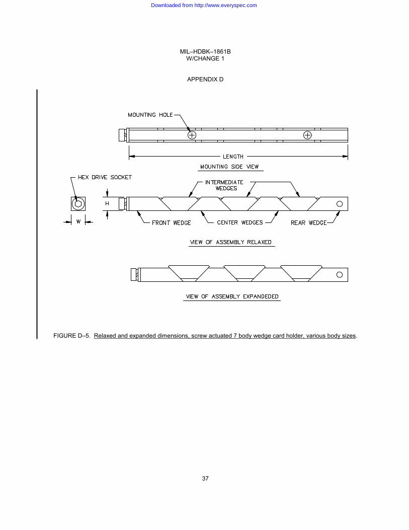
MIL–HDBK–1861B W/CHANGE 1
APPENDIX D
FIGURE D–5. Relaxed and expanded dimensions, screw actuated 7 body wedge card holder, various body sizes.
37
Downloaded from http://www.everyspec.com

MIL–HDBK–1861B W/CHANGE 1
APPENDIX D
This page intentionally left blank.
38
Downloaded from http://www.everyspec.com
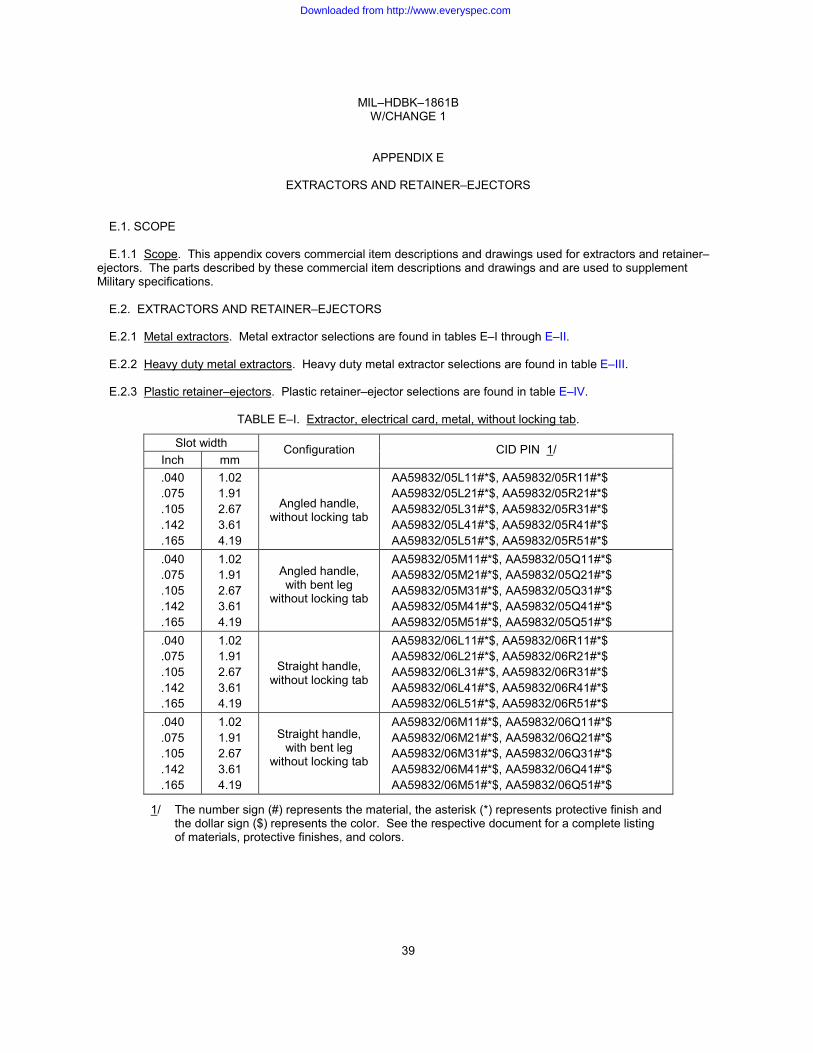
MIL–HDBK–1861B W/CHANGE 1
APPENDIX E
EXTRACTORS AND RETAINER–EJECTORS
E.1. SCOPE
E.1.1 Scope. This appendix covers commercial item descriptions and drawings used for extractors and retainer–ejectors. The parts described by these commercial item descriptions and drawings and are used to supplement Military specifications.
E.2. EXTRACTORS AND RETAINER–EJECTORS
E.2.1 Metal extractors. Metal extractor selections are found in tables E–I through E–II.
E.2.2 Heavy duty metal extractors. Heavy duty metal extractor selections are found in table E–III.
E.2.3 Plastic retainer–ejectors. Plastic retainer–ejector selections are found in table E–IV.
TABLE E–I. Extractor, electrical card, metal, without locking tab.
Slot width Configuration CID PIN 1/ Inch mm .040 .075 .105 .142 .165
1.02 1.91 2.67 3.61 4.19
Angled handle, without locking tab
AA59832/05L11#*$, AA59832/05R11#*$ AA59832/05L21#*$, AA59832/05R21#*$ AA59832/05L31#*$, AA59832/05R31#*$ AA59832/05L41#*$, AA59832/05R41#*$ AA59832/05L51#*$, AA59832/05R51#*$
.040
.075
.105
.142
.165
1.02 1.91 2.67 3.61 4.19
Angled handle, with bent leg
without locking tab
AA59832/05M11#*$, AA59832/05Q11#*$ AA59832/05M21#*$, AA59832/05Q21#*$ AA59832/05M31#*$, AA59832/05Q31#*$ AA59832/05M41#*$, AA59832/05Q41#*$ AA59832/05M51#*$, AA59832/05Q51#*$
.040
.075
.105
.142
.165
1.02 1.91 2.67 3.61 4.19
Straight handle, without locking tab
AA59832/06L11#*$, AA59832/06R11#*$ AA59832/06L21#*$, AA59832/06R21#*$ AA59832/06L31#*$, AA59832/06R31#*$ AA59832/06L41#*$, AA59832/06R41#*$ AA59832/06L51#*$, AA59832/06R51#*$
.040
.075
.105
.142
.165
1.02 1.91 2.67 3.61 4.19
Straight handle,
with bent leg without locking tab
AA59832/06M11#*$, AA59832/06Q11#*$ AA59832/06M21#*$, AA59832/06Q21#*$ AA59832/06M31#*$, AA59832/06Q31#*$ AA59832/06M41#*$, AA59832/06Q41#*$ AA59832/06M51#*$, AA59832/06Q51#*$
1/ The number sign (#) represents the material, the asterisk (*) represents protective finish and the dollar sign ($) represents the color. See the respective document for a complete listing of materials, protective finishes, and colors.
39
Downloaded from http://www.everyspec.com

MIL–HDBK–1861B W/CHANGE 1
APPENDIX E
TABLE E–II. Extractor, electrical card, metal, with locking tab.
Slot width Configuration DESC PIN 1/ Inch mm .040 .075 .105 .142 .165
1.02 1.91 2.67 3.61 4.19
Angled handle, with lock tab
84191–09*#, 84191–10*# 84191–11*#, 84191–12*# 84191–13*#, 84191–14*# 84191–15*#, 84191–16*# 84191–35*#, 84191–36*#
.040
.075
.105
.142
.165
1.02 1.91 2.67 3.61 4.19
Straight handle, with lock tab
84191–17*#, 84191–18*# 84191–19*#, 84191–20*# 84191–21*#, 84191–22*# 84191–23*#, 84191–24*# 84191–37*#, 84191–38*#
1/ The asterisk (*) represents protective finish and the number sign (#) represents the material. The finish options are black anodize (designator B), chemical film (designator C), chemical film with the electronic sensitive device symbol (designator E), and passivation (designator P) for corrosion stainless steel parts. The material options are aluminum alloy 5052–H32 (designator A), aluminum alloy 6061–T6 (designator T), and type 301 stainless steel (designator S).
40
Downloaded from http://www.everyspec.com

MIL–HDBK–1861B W/CHANGE 1
APPENDIX E
TABLE E–III. Extractor, electrical card, metal, heavy duty.
Slot width Configuration CID PIN 1/ Inch mm .048 .080 .110 .140
1.22 2.03 2.79 3.56
Non-locking, mechanical advantage of 5.5:1 Non-locking, mechanical advantage of 5.5:1 Non-locking, mechanical advantage of 5.5:1 Non-locking, mechanical advantage of 5.5:1
AA59832/01AF1$# AA59832/01AS1$# AA59832/01AT1$# AA59832/01AE1$#
.048
.080
.110
.140
1.22 2.03 2.79 3.56
Non-locking, mechanical advantage of 3.3:1 Non-locking, mechanical advantage of 3.3:1 Non-locking, mechanical advantage of 3.3:1 Non-locking, mechanical advantage of 3.3:1
AA59832/02SF1$# AA59832/02SS1$# AA59832/02ST1$# AA59832/02SE1$#
.048
.080
.110
.140
1.22 2.03 2.79 3.56
Non-locking, mechanical advantage of 4.2:1 Non-locking, mechanical advantage of 4.2:1 Non-locking, mechanical advantage of 4.2:1 Non-locking, mechanical advantage of 4.2:1
AA59832/02MF1$# AA59832/02MS1$# AA59832/02MT1$# AA59832/02ME1$#
.048
.080
.110
.140
1.22 2.03 2.79 3.56
Non-locking, mechanical advantage of 7:1 Non-locking, mechanical advantage of 7:1 Non-locking, mechanical advantage of 7:1 Non-locking, mechanical advantage of 7:1
AA59832/02LF1$# AA59832/02LS1$# AA59832/02LT1$# AA59832/02LE1$#
.080
.110
.140
2.03 2.79 3.56
Locking, mechanical advantage of 4.2:1 Locking, mechanical advantage of 4.2:1 Locking, mechanical advantage of 4.2:1
AA59832/03LS1$# AA59832/03LT1$# AA59832/03LE1$#
.080
.110
.140
2.03 2.79 3.56
Locking, mechanical advantage of 7:1 Locking, mechanical advantage of 7:1 Locking, mechanical advantage of 7:1
AA59832/03LS1$# AA59832/03LT1$# AA59832/03LE1$#
1/ The dollar sign ($) represents protective finish and the number sign (#) represents color. The finish options are anodize (designator A) and chemical film (designator C). The color options are black (designator B) and red (designator R) for anodize and clear (designator C) or gold (designator G) for chemical film.
41
Downloaded from http://www.everyspec.com

MIL–HDBK–1861B W/CHANGE 1
APPENDIX E
TABLE E–IV. Retainer–ejector, electrical card, plastic.
Slot width Material DESC drawing PIN 1/ Inch mm .075 .075 .075 .075 .105 .105 .105 .100
1.91 1.91 1.91 1.91 2.67 2.67 2.67 2.54
Nylon Nylon Nylon Nylon Nylon Nylon Nylon Nylon
83023–01* 83023–02* 83023–03* 83023–04* 83023–05* 83023–06* 83023–07* 83023–08*
.075
.140
.075
.075
.070
.075
1.91 3.56 1.91 1.91 1.78 1.91
Glass filled nylon Glass filled nylon Glass filled nylon Glass filled nylon Nylon Glass filled polycarbonate
83023–09* 83023–10* 83023–11* 83023–12* 83023–13* 83023–14*
.070
.100
.140
.070
.075
.100
.140
.075
.075
1.78 2.54 3.56 1.78 1.91 2.54 3.56 1.91 1.91
Nylon Nylon Glass filled polycarbonate Nylon Nylon Nylon Nylon Nylon Nylon
83023–15* 83023–16* 83023–17* 83023–18* 83023–19* 83023–20* 83023–21* 83023–22* 83023–23*
.075
.100
.074
.100
.140
1.91 2.54 1.89 2.54 3.56
Glass filled polycarbonate Glass filled polycarbonate Glass filled polycarbonate Glass filled polycarbonate Glass filled polycarbonate
83023–24* 83023–25* 83023–26* 83023–27* 83023–28*
1/ The asterisk (*) represents one of six colors available.
42
Downloaded from http://www.everyspec.com

MIL–HDBK–1861B W/CHANGE 1
Custodians: Preparing activity:
Army – CR DLA – CC Navy – EC Air Force – 85 Project 5998–2014–011 DLA – CC
Review activity:
Air Force – 99 NOTE: The activities listed above were interested in this document as of the date of this document. Since organizations and responsibilities can change, you should verify the currency of the information above using the ASSIST Online database at https://assist.dla.mil.
43
Downloaded from http://www.everyspec.com