department of defense handbook standard microcircuit drawings€¦ · department of defense...
TRANSCRIPT

MIL-HDBK-780D 28 May 2004 SUPERSEDING MIL-HDBK-780C 15 August 1997
DEPARTMENT OF DEFENSE HANDBOOK
STANDARD MICROCIRCUIT DRAWINGS
This handbook is for guidance only. Do not cite this document as a requirement.
AMSC N/A FSC 5962
NOT MEASUREMENT SENSITIVE

MIL-HDBK-780D
ii
FOREWORD
1. This handbook is approved for use by all Departments and Agencies of the Department of Defense.
2. Comments, suggestions, or questions on this document should be addressed to Commander, Defense Supply Center Columbus ATTN: DSCC-VA, P O Box 3990, Columbus, OH 43218-3990 or emailed to [email protected]. Since contact information can change, you may want to verify the currency of this address information using the ASSIST Online database at www.dodssp.daps.mil.
3. This handbook provides guidance on standard microcircuit drawings (SMD's). The purpose of the SMD program is to minimize the proliferation of specification and source control drawings within the Department of Defense (DoD). The use of one SMD for an item of supply in use by DoD Departments and Agencies is the objective of this program.
4. It is intended that the issue of SMD's affect DoD procurement through minimizing the proliferation of duplicate drawings for an item of supply.
5. It is also the objective of the SMD Program that the resulting drawing be multi-user in actual implementation.
6. The application of this handbook is currently confined to the acquisition of microcircuits until such time that applicability to federal supply classes other than FSC 5962 is deemed appropriate.

MIL-HDBK-780D
iii
CONTENTS PARAGRAPH PAGE
1. SCOPE ........................................................................................................................... 1 1.1 Scope ...................................................................................................................... 1
2. APPLICABLE DOCUMENTS .......................................................................................... 1 2.1 General ................................................................................................................... 1 2.2 Government documents .......................................................................................... 1 2.2.1 Specifications, standards, and handbooks ............................................................. 1 2.3 Non-Government publications ................................................................................ 1 2.4 Order of precedence ............................................................................................... 2
3. DEFINITIONS ................................................................................................................. 2 3.1 Standard microcircuit drawing ................................................................................. 2 3.2 General specification .............................................................................................. 2 3.3 Military Parts Control Advisory Group (MPCAG) ..................................................... 2
4. GENERAL GUIDANCE ................................................................................................... 2 4.1 Introduction ............................................................................................................ 2 4.2 Sectional arrangement of an SMD .......................................................................... 2 4.2.1 Subject matter ......................................................................................................... 2 4.2.2 Section 1 ................................................................................................................ 2 4.2.2.1 Scope....................................................................................................................... 2 4.2.2.2 Part or Identifying Number (PIN) ............................................................................. 2 4.2.3 Section 2 ................................................................................................................. 3 4.2.3.1 Listing of references ............................................................................................... 3 4.2.3.1.1 Government documents .......................................................................................... 3 4.2.3.1.2 Nongovernment standards and other publications ................................................. 4 4.2.3.1.3 Order of precedence ............................................................................................... 4 4.2.4 Section 3 ................................................................................................................. 4 4.2.4.1 Requirements .......................................................................................................... 4 4.2.4.1.1 Organization of requirements .................................................................................. 5 4.2.4.1.2 Sequencing of requirements and tests ................................................................... 5 4.2.4.2 Materials ................................................................................................................. 5 4.2.4.3 Design ..................................................................................................................... 5 4.2.4.4 Construction ............................................................................................................ 5 4.2.4.5 Hardware ................................................................................................................ 5 4.2.4.6 Performance characteristics ................................................................................... 5 4.2.4.7 Dimensions ............................................................................................................. 6 4.2.4.8 Finish ...................................................................................................................... 6 4.2.4.9 Marking ................................................................................................................... 6 4.2.4.10 Selection of alternative materials,
construction, etc. ................................................................................................ 6 4.2.4.11 Certificate of compliance ........................................................................................ 6 4.2.4.12 Certificate of conformance ...................................................................................... 6 4.2.4.13 Notification of change or discontinuance ................................................................ 6

MIL-HDBK-780D
iv
CONTENTS PARAGRAPH PAGE
4.2.4.14 Verification and review ............................................................................................ 6 4.2.5 Section 4 ................................................................................................................. 6 4.2.5.1 Quality assurance provisions .................................................................................. 6 4.2.5.2 Responsibility for inspection ................................................................................... 6 4.2.5.3 Responsibility for compliance ................................................................................. 7 4.2.5.4 Conformance inspection ......................................................................................... 7 4.2.5.4.1 Conformance inspection sampling .......................................................................... 7 4.2.5.5 Classification of conformance inspections .............................................................. 7 4.2.5.6 Tabular listing of conformance inspection .............................................................. 8 4.2.6 Section 5 ................................................................................................................. 8 4.2.6.1 Packaging, packing, and marking ........................................................................... 8 4.2.7 Section 6 ................................................................................................................. 8 4.2.7.1 Notes ....................................................................................................................... 8 4.2.7.2 Intended use ........................................................................................................... 8 4.2.7.3 Comments ............................................................................................................... 8 4.2.7.4 Sources of supply ................................................................................................... 8 4.3 Approved SMD's ..................................................................................................... 9 4.3.1 SMD user ................................................................................................................ 9 4.3.2 Changes to SMD's ................................................................................................. 9 4.3.3 Nonconcurrence with proposed changes ................................................................ 9
5. DETAILED GUIDANCE ................................................................................................... 9 5.1 Introduction ............................................................................................................. 9 5.2 Drawing preparation ................................................................................................ 9 5.3 Initial drawing preparation ....................................................................................... 9 5.3.1 Blank drawings ........................................................................................................ 9 5.3.2 SMD coordination ................................................................................................... 9 5.3.3 Preliminary and final draft submittal ........................................................................ 9 5.3.3.1 Preliminary draft construction ................................................................................. 9 5.3.4 Maintenance ........................................................................................................... 9 5.3.5 SMD content preparation ........................................................................................ 9 5.3.5.1 Section 1, scope ..................................................................................................... 9 5.3.5.1.1 Scope ...................................................................................................................... 9 5.3.5.1.2 PIN .......................................................................................................................... 9 5.3.5.1.2.1 PIN length ............................................................................................................... 10 5.3.5.1.3 Radiation hardness assurance (RHA) Designator .................................................. 10 5.3.5.1.4 Device type(s) ......................................................................................................... 10 5.3.5.1.5 Device class designator .......................................................................................... 10 5.3.5.1.6 Case outline ............................................................................................................ 10 5.3.5.1.7 Lead finish .............................................................................................................. 10 5.3.5.1.8 Absolute maximum ratings ...................................................................................... 10 5.3.5.1.9 Recommended operating conditions ...................................................................... 10
MIL-HDBK-780D
v
CONTENTS PARAGRAPH PAGE
5.3.5.2 Section 2, applicable documents ............................................................................ 10 5.3.5.2.1 Order of precedence ............................................................................................... 10 5.3.5.3 Section 3, requirements .......................................................................................... 10 5.3.5.3.1 Item requirements ................................................................................................... 10 5.3.5.3.2 Design, construction and physical dimensions ....................................................... 10 5.3.5.3.3 Terminal connections .............................................................................................. 10 5.3.5.3.4 Block diagram ......................................................................................................... 11 5.3.5.3.5 Truth tables ............................................................................................................. 11 5.3.5.3.6 Case outline(s) ........................................................................................................ 11 5.3.5.3.7 Electrical performance characteristics and ............................................................. 11
post irradiation parameter limits 5.3.5.3.8 Electrical test requirements .................................................................................... 11 5.3.5.3.9 Marking ................................................................................................................... 11 5.3.5.3.10 Tables ..................................................................................................................... 11 5.3.5.3.11 Graphics .................................................................................................................. 11 5.3.5.3.12 Certificate of compliance ........................................................................................ 11 5.3.5.3.13 Certificate of conformance ...................................................................................... 11 5.3.5.3.14 Notification of change ............................................................................................. 11 5.3.5.3.15 Verification of change ............................................................................................. 11 5.3.6 Section 4, verification .............................................................................................. 12 5.3.6.1 Sampling and inspection ......................................................................................... 12 5.3.6.2 Screening ................................................................................................................ 12 5.3.6.3 Qualification inspection ........................................................................................... 12 5.3.6.4 Conformance inspection ......................................................................................... 12 5.3.6.4.1 Group A inspection ................................................................................................. 12 5.3.6.4.2 Group C inspection ................................................................................................. 12 5.3.6.4.3 Group D inspection ................................................................................................. 12 5.3.6.4.4 Group E inspection ................................................................................................. 12 5.3.6.5 Tables, electrical tests ............................................................................................ 12 5.3.7 Section 5, packaging .............................................................................................. 12 5.3.7.1 Packaging requirements ......................................................................................... 12 5.3.8 Section 6, notes ...................................................................................................... 12 5.3.8.1 Intended use ........................................................................................................... 12 5.3.8.1.1 Replaceability .......................................................................................................... 12 5.3.8.1.2 Substitutability ......................................................................................................... 13 5.3.8.2 Configuration control of SMD's ............................................................................... 13 5.3.8.3 Record of users ....................................................................................................... 13 5.3.8.4 Comments ............................................................................................................... 13 5.3.8.5 Abbreviations, symbols, and definitions .................................................................. 13 5.3.8.6 Sources of supply ................................................................................................... 13
MIL-HDBK-780D
vi
CONTENTS PARAGRAPH PAGE
6 NOTES ............................................................................................................................ 13 6.1 Intended use ................................................................................................................... 13 6.1.1 Standard microcircuit drawing program (SMDP) ............................................................. 13 6.2 Draft construction ............................................................................................................ 13 6.3 Certificate of compliance ................................................................................................ 13 6.4 Subject term (key word) listing ........................................................................................ 13 6.5 Changes from previous issue ......................................................................................... 13
FIGURES
1. Drawing, title sheet .............................................................................................................. 14 2. Drawing, continuation sheet ................................................................................................. 15 3. Certificate of compliance ...................................................................................................... 16 4. SMD preparation flowchart ................................................................................................... 19 5. SMD with boilerplate ............................................................................................................ 21 6. Sample SMD ........................................................................................................................ 29

MIL-HDBK-780D
1
1. SCOPE
1.1 Scope. This handbook provides guidance and information concerning standard microcircuit drawings (SMD's). System applications are subject to the approval of the applicable program office. This handbook is for guidance only and cannot be cited as a requirement.
2. APPLICABLE DOCUMENTS
2.1 General. The documents listed below are not necessarily all of the documents referenced herein, but are
those needed to understand the information provided by this handbook. 2.2 Government documents.
2.2.1 Specifications, standards, and handbooks. The following specifications, standards, and handbooks form a part of this document to the extent specified herein.
DEPARTMENT OF DEFENSE SPECIFICATIONS
MIL-PRF-38534 - Hybrid Microcircuits, General Specification for. MIL-PRF-38535 - Integrated Circuits (Microcircuits) Manufacturing, General Specification for.
DEPARTMENT OF DEFENSE STANDARD
MIL-STD-883 - Test Method Standard Microcircuits
DEPARTMENT OF DEFENSE HANDBOOK
MIL-HDBK-103 - List of Standard Microcircuit Drawings (SMD's)
(Copies of these documents are available online at http://assist.daps.dla.mil;quicksearch/ or
www.dodssp.daps.mil or from the Standardization Document Order Desk, 700 Robbins Avenue, Building 4D, Philadelphia, PA 19111-5094.)
2.3 Non-Government publications. The following documents form a part of this document to the extent specified herein.
AMERICAN SOCIETY OF MECHANICAL ENGINEERS (ASME)
ASME Y14.5M - Dimensioning and Tolerancing ASME Y14.100 - Engineering Drawing Practices
(Copies of these documents are available online at http://www.asme.org/ or from the American Society of
Mechanical Engineers, Three Park Avenue, New York, NY 10016-5990). 2.4 Order of precedence. In the event of a conflict between the text of this document and the references cited herein, the text of this document takes precedence. Nothing in this document, however, supersedes applicable laws and regulations unless a specific exemption has been obtained.
MIL-HDBK-780D
2
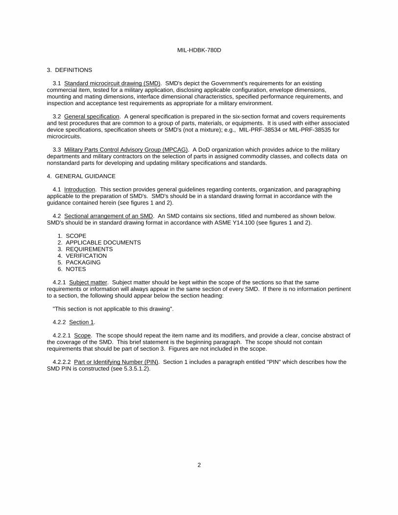
3. DEFINITIONS
3.1 Standard microcircuit drawing (SMD). SMD's depict the Government's requirements for an existing commercial item, tested for a military application, disclosing applicable configuration, envelope dimensions, mounting and mating dimensions, interface dimensional characteristics, specified performance requirements, and inspection and acceptance test requirements as appropriate for a military environment.
3.2 General specification. A general specification is prepared in the six-section format and covers requirements and test procedures that are common to a group of parts, materials, or equipments. It is used with either associated device specifications, specification sheets or SMD's (not a mixture); e.g., MIL-PRF-38534 or MIL-PRF-38535 for microcircuits.
3.3 Military Parts Control Advisory Group (MPCAG). A DoD organization which provides advice to the military departments and military contractors on the selection of parts in assigned commodity classes, and collects data on nonstandard parts for developing and updating military specifications and standards. 4. GENERAL GUIDANCE
4.1 Introduction. This section provides general guidelines regarding contents, organization, and paragraphing applicable to the preparation of SMD's. SMD's should be in a standard drawing format in accordance with the guidance contained herein (see figures 1 and 2).
4.2 Sectional arrangement of an SMD. An SMD contains six sections, titled and numbered as shown below. SMD's should be in standard drawing format in accordance with ASME Y14.100 (see figures 1 and 2).
1. SCOPE 2. APPLICABLE DOCUMENTS 3. REQUIREMENTS 4. VERIFICATION 5. PACKAGING 6. NOTES
4.2.1 Subject matter. Subject matter should be kept within the scope of the sections so that the same
requirements or information will always appear in the same section of every SMD. If there is no information pertinent to a section, the following should appear below the section heading:
"This section is not applicable to this drawing".
4.2.2 Section 1.
4.2.2.1 Scope. The scope should repeat the item name and its modifiers, and provide a clear, concise abstract of the coverage of the SMD. This brief statement is the beginning paragraph. The scope should not contain requirements that should be part of section 3. Figures are not included in the scope.
4.2.2.2 Part or Identifying Number (PIN). Section 1 includes a paragraph entitled "PIN" which describes how the SMD PIN is constructed (see 5.3.5.1.2).
MIL-HDBK-780D
3
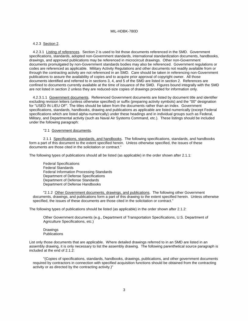
4.2.3 Section 2.
4.2.3.1 Listing of references. Section 2 is used to list those documents referenced in the SMD. Government specifications, standards, adopted non-Government standards, international standardization documents, handbooks, drawings, and approved publications may be referenced in microcircuit drawings. Other non-Government documents promulgated by non-Government standards bodies may also be referenced. Government regulations or codes are referenced as applicable. Military Activity Regulations and other documents not readily available from or through the contracting activity are not referenced in an SMD. Care should be taken in referencing non-Government publications to assure the availability of copies and to acquire prior approval of copyright owner. All those documents identified and referred to in sections 3, 4, and 5 of the SMD are listed in section 2. References are confined to documents currently available at the time of issuance of the SMD. Figures bound integrally with the SMD are not listed in section 2 unless they are reduced-size copies of drawings provided for information only.
4.2.3.1.1 Government documents. Referenced Government documents are listed by document title and identifier excluding revision letters (unless otherwise specified) or suffix (preparing activity symbols) and the "00" designation for "USED IN LIEU OF". The titles should be taken from the documents rather than an index. Government specifications, standards, handbooks, drawing and publications as applicable are listed numerically (except Federal specifications which are listed alpha-numerically) under these headings and in individual groups such as Federal, Military, and Departmental activity (such as Naval Air Systems Command, etc.). These listings should be included under the following paragraph:
"2.1 Government documents.
2.1.1 Specifications, standards, and handbooks. The following specifications, standards, and handbooks form a part of this document to the extent specified herein. Unless otherwise specified, the issues of these documents are those cited in the solicitation or contract." The following types of publications should all be listed (as applicable) in the order shown after 2.1.1:
Federal Specifications Federal Standards Federal Information Processing Standards Department of Defense Specifications Department of Defense Standards
Department of Defense Handbooks
"2.1.2 Other Government documents, drawings, and publications. The following other Government documents, drawings, and publications form a part of this drawing to the extent specified herein. Unless otherwise specified, the issues of these documents are those cited in the solicitation or contract."
The following types of publications should be listed (as applicable) in the order shown after 2.1.2:
Other Government documents (e.g., Department of Transportation Specifications, U.S. Department of Agriculture Specifications, etc.)
Drawings Publications
List only those documents that are applicable. Where detailed drawings referred to in an SMD are listed in an assembly drawing, it is only necessary to list the assembly drawing. The following parenthetical source paragraph is included at the end of 2.1.2:
"(Copies of specifications, standards, handbooks, drawings, publications, and other government documents required by contractors in connection with specified acquisition functions should be obtained from the contracting activity or as directed by the contracting activity.)"
MIL-HDBK-780D
4
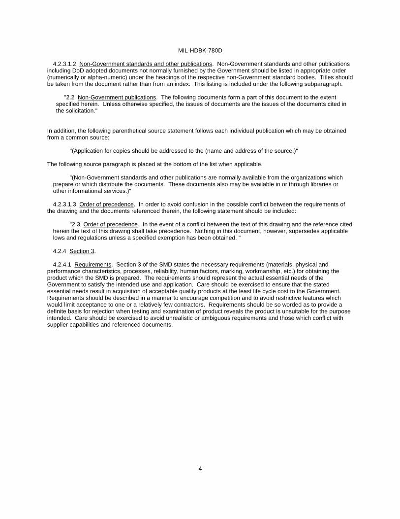
4.2.3.1.2 Non-Government standards and other publications. Non-Government standards and other publications
including DoD adopted documents not normally furnished by the Government should be listed in appropriate order (numerically or alpha-numeric) under the headings of the respective non-Government standard bodies. Titles should be taken from the document rather than from an index. This listing is included under the following subparagraph.
"2.2 Non-Government publications. The following documents form a part of this document to the extent specified herein. Unless otherwise specified, the issues of documents are the issues of the documents cited in the solicitation."
In addition, the following parenthetical source statement follows each individual publication which may be obtained from a common source:
"(Application for copies should be addressed to the (name and address of the source.)" The following source paragraph is placed at the bottom of the list when applicable.
"(Non-Government standards and other publications are normally available from the organizations which prepare or which distribute the documents. These documents also may be available in or through libraries or other informational services.)"
4.2.3.1.3 Order of precedence. In order to avoid confusion in the possible conflict between the requirements of
the drawing and the documents referenced therein, the following statement should be included:
"2.3 Order of precedence. In the event of a conflict between the text of this drawing and the reference cited herein the text of this drawing shall take precedence. Nothing in this document, however, supersedes applicable lows and regulations unless a specified exemption has been obtained. "
4.2.4 Section 3.
4.2.4.1 Requirements. Section 3 of the SMD states the necessary requirements (materials, physical and
performance characteristics, processes, reliability, human factors, marking, workmanship, etc.) for obtaining the product which the SMD is prepared. The requirements should represent the actual essential needs of the Government to satisfy the intended use and application. Care should be exercised to ensure that the stated essential needs result in acquisition of acceptable quality products at the least life cycle cost to the Government. Requirements should be described in a manner to encourage competition and to avoid restrictive features which would limit acceptance to one or a relatively few contractors. Requirements should be so worded as to provide a definite basis for rejection when testing and examination of product reveals the product is unsuitable for the purpose intended. Care should be exercised to avoid unrealistic or ambiguous requirements and those which conflict with supplier capabilities and referenced documents.

MIL-HDBK-780D
5
4.2.4.1.1 Organization of requirements. Care should be taken to provide for a systematic arrangement of
requirements to facilitate design, manufacturing, and inspections.
4.2.4.1.2 Sequencing of requirements and tests. When possible, the test paragraphs in section 4 should be placed in the same sequence as the requirement paragraph in section 3. An example of sequencing requirements and tests is as follows:
Requirement Test
3.6 Shock 4.7.1 Shock 3.7 Vibration 4.7.2 Vibration 3.8 Noise 4.7.3 Noise 3.9 Electromagnetic interference 4.7.4 Electromagnetic interference
4.2.4.2 Materials. Requirements for materials to be used in the item(s) covered by the SMD are stated under this
heading, except where it is more practical to include the information in other paragraphs. Requirements of general nature should be followed by specific requirements for the material. Definitive documents should be referenced for the material when such documents cover materials of the minimum required quality.
4.2.4.3 Design. The major functional characteristics should be specified. The intended use is covered in Section 6 of the SMD. Detailed design should be covered in individual paragraphs.
4.2.4.4 Construction. The specified points of construction should be included, as applicable. Construction requirements should be related to the physical limitations imposed and the stresses that equipment is expected to withstand.
4.2.4.5 Hardware. Standard military hardware should be designed into assemblies to the maximum extent possible. This includes mounting hardware when required to be furnished with the product. Selection of the hardware should be made from existing standards (such as MS, NAS, and AN standards), if possible, or from other standards required by contract.
4.2.4.6 Performance characteristics. General and detail performance characteristics should be included under this or other appropriate headings specifying what is expected of the commodity. Each requirement in Section 3 should have a corresponding test method in section 4. The requirement paragraph should reference the applicable test paragraph; "(see 4. )".

MIL-HDBK-780D
6
4.2.4.7 Dimensions. Dimensions and tolerances will be in accordance with ASME Y14.5M.
4.2.4.8 Finish. Finish should include such properties as surface roughness, freedom from burrs, corrosion,
metallic and nonmetallic coatings.
4.2.4.9 Marking. Requirements for marking should reference MIL-PRF-38534 or MIL-PRF-38535. When section 3 specifies that certain item marking is to be placed on the unit container, section 5 should specify the container marking described. When part numbering is a requirement, the section 3 paragraph should reference section 1 paragraph or the appropriate appendix for a description of the part numbering scheme.
4.2.4.10 Selection of alternative materials, construction, etc. When alternate acceptable materials, construction, appearance, or other characteristics are stated in SMD's without specific provisions as to selectivity to be exercised in acquisition, the alternatives are to be considered interchangeable. In such cases, it should be clearly stated in the SMD that the selection of a specific alternative is at the option of the contractor.
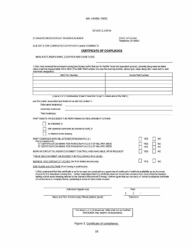
4.2.4.11 Certificate of compliance. A certificate of compliance (see figure 3) is required from a manufacturer in order to be listed as a source of supply in MIL-HDBK-103 (see 4.2.7.4). The certificate of compliance submitted prior to listing as a source of supply should affirm that the manufacturer's product meets the requirements of the applicable specification (see 6.3).
4.2.4.12 Certificate of conformance. The certificate of conformance should be in accordance with the applicable general specification and should be provided with each lot of items delivered to the SMD.
4.2.4.13 Notification of change or discontinuance. Requirements for notification of change or discontinuance should reference MIL-PRF-38534 or MIL-PRF-38535.
4.2.4.14 Verification and review. The Government retains the option to review the device manufacturer's facility and applicable required documentation.
4.2.5 Section 4.
4.2.5.1 Verification. Section 4 should include all inspections (by reference when applicable) to be performed in order to determine that the item conforms to requirements of sections 3 and 5 of the SMD.
4.2.5.2 Responsibility for inspection. Unless otherwise specified in the contract or purchase order, the contractor is responsible for all inspection requirements specified. Except as otherwise specified in the contract or purchase order, the contractor may use his own or any other facilities suitable for the performance of the inspection requirements, unless disapproved by the Government. The Government reserves the right to perform any of the inspections set forth in the SMD where such inspections are deemed necessary to assure supplies and services conform to prescribed requirements.

MIL-HDBK-780D
7
4.2.5.3 Responsibility for compliance. All items must meet all requirements of sections 3 and 5 of the SMD. The
inspection set forth in the SMD should become part of the contractor's overall inspection system or quality program. The absence of any inspection requirements in the SMD does not relieve the contractor of the responsibility of assuring that all products or supplies submitted to the Government for acceptance comply with all requirements of the contract. Sampling in conformance inspection does not authorize submission of known defective material, either indicated or actual, nor does it commit the Government to acceptance of defective material.
4.2.5.4 Conformance inspection. The tests listed in section 4 of the SMD to determine conformance with sections 3 and 5 requirements, should include, when necessary, a measurement or comparison with specified characteristics and checks and tests of the performance and reliability requirements. Each item must meet all sections 3 and 5 requirements. The test methods in section 4 of the SMD are minimum inspection and test methods to be used to document compliance to the SMD requirement.
4.2.5.4.1 Conformance inspection sampling. When it is desirable to specify the sampling procedure to be used by contractors for the performance of conformance inspection, the sampling procedure should:
a. Impose no inspection procedures that are less efficient and effective than would normally be used by the industry.
b. Clearly identify the sampling plan to be used in the manufacturing process when inspections are to be
performed at intermediate points, as well as, on the end item.
c. Be capable of assuring compliance with requirements under various conditions of manufacturing or purchasing, e.g., mass or job lot production and large or small lot purchasing.
When inspections are to be based on lots of material, a definition of a lot size(s) should be furnished in this section by reference, if applicable. Restrictions concerning the formation of inspection lots such as restricting inspection lots of units of the same type, class, size, should be specified. Restriction of units forming the lot of those produced from the same assembly line, etc., should also be specified, when applicable.
4.2.5.5 Classification of conformance inspections. Conformance inspections should be classified into group A, B, C, D or E in accordance with the following groupings, when applicable:
Group A - Nondestructive inspections of all items produced or all samples from an inspection lot demonstrate product compliance with contractual requirements. Group A inspection examines characteristics most affected by variations in production processes or skills, and functions vital to successful completion of the design mission.
Group B - Generally nondestructive inspections that are more complex or of a longer duration than group A inspection. Group B inspection examines characteristics more affected by part or equipment quality and less affected by variations in production processes or skills, and functions requiring special fixtures or environments. Fewer samples are inspected than for group A inspections and test articles may be offered for acceptance with little or no refurbishment. Each commodity should be individually evaluated regarding its issue after performing group B and C inspections.
Group C - Periodic and generally destructive tests of characteristics depending upon product design and materials.
Group C inspection consists of more complex tests, usually including emulated service environments, is generally destructive and may require major refurbishment before tested articles can be used by the services. Tests are based on production quantities or time period.
Group D - Destructive test or test of long duration that consumes all or a considerable portion of design service life. Articles subjected to group D inspection should not be issued. Tests are performed on few samples based on production quantities or time period.

MIL-HDBK-780D
8
4.2.5.6 Tabular listing of conformance inspection. Where it will lead to better understanding of their functions, the
inspections should be listed as group A, B, C, D or E in tabular form with appropriate references to applicable requirements, and inspection methods in MIL-STD-883, MIL-PRF-38534, or MIL-PRF-38535 as illustrated below:
“ 4.3 Conformance inspection. Conformance inspection shall be in accordance with method 5005 of MIL-STD-883 including groups A, B, C, and D inspections. The following additional criteria shall apply.
Test requirements
Subgroups (in accordance with MIL-STD-883, method 5005, table I)
Interim electrical parameters
Final electrical test parameters
Group A test requirements
Groups C and D end-point electrical parameters
“
4.2.6 Section 5.
4.2.6.1 Packaging, packing, and marking. Packaging, packing, and marking should be as specified in the applicable general specification.
4.2.7 Section 6.
4.2.7.1 Notes. Section 6 should contain information of a general or explanatory nature and no requirements should appear therein. It should contain information designed to assist in determining the applicability of the SMD.
4.2.7.2 Intended use. Items conforming to the SMD are intended for use for Government microcircuit applications (original equipment), design applications, and logistics purposes.
4.2.7.3 Comments. Comments on the SMD should be directed to the applicable MPCAG.
4.2.7.4 Sources of supply. Sources of supply will be identified in MIL-HDBK-103 (see 4.3) or the appropriate Qualified Manufacturers List (QML). The vendors so listed will have agreed to the SMD and submitted a certificate of compliance (see 4.2.4.11) and completed qualification requirements. Additional sources will be added to these listings as they become available.

MIL-HDBK-780D
9
4.3 Approved SMD's. SMD's in use by DoD and industry are listed in MIL-HDBK-103.
4.3.1 SMD user. When a contractor or DoD component has a system application for an existing SMD, as listed in MIL-HDBK-103, it is essential that the applicable MPCAG be informed accordingly.
4.3.2 Changes to SMD's. Utilizing user identification in accordance with MIL-HDBK-103, proposed changes or draft revisions are coordinated with all users of record. Changes are implemented in accordance with the provisions of MIL-PRF-38535. SMD's are maintained by the MPCAG. Approved revisions to SMD's are distributed by the MPCAG to all known users of record.
4.3.3 Nonconcurrence with proposed changes. User nonconcurrence with a proposed change to an SMD requires MPCAG resolution of the stated nonconcurrence. Unresolved nonconcurrence will require MPCAG action as appropriate, i.e., nonconcurrence reply, with technical justification, to the originator of the change proposal, new SMD's that address the diverse needs of the users involved, or advisory to user of need to generate new part acquisition documentation.
5. DETAILED GUIDANCE
5.1 Introduction. This section contains guidance for SMD's.
5.2 Drawing preparation. In coordination with and with the approval of the applicable Program Office, a MPCAG (see 3.3) will respond to a parts approval request with a drawing preparation package consisting of the following:
a. Drawing number
b. All known sources of supply
5.3 Initial drawing preparation.
5.3.1 Blank drawings. Blank drawings are not provided. Drawing format should be in conformance to figures 1 and 2.
5.3.2 SMD coordination. Preliminary draft coordinations with MPCAG and device manufacturers, comment resolution, certificate of compliance transmittal and final SMD preparation should be in conformance with figure 4.
5.3.3 Preliminary and final draft submittal. Preliminary draft will be typed and spaced in accordance with the drawing format (figures 1 and 2). Handwritten or pasted catalog excerpts are not acceptable. This preliminary draft may be on standard 8 1/2" x 11" paper. Once started by the contractor, it is expected that the process described herein will be completed. Preliminary drafts should be clearly marked preliminary draft on the first and last pages.
5.3.3.1 Preliminary draft construction. The preliminary draft is constructed through communication with the applicable MPCAG (see 6.2).
5.3.4 Maintenance. Maintenance of approved SMD's is the responsibility of the applicable MPCAG.
5.3.5 SMD content preparation. The following detail should be reviewed in conjunction with figure 5, especially regarding "boilerplate" location and content. The following detail reflects the current exclusive applicability of SMD's to Microcircuits.
5.3.5.1 Section 1, scope. 1. SCOPE should be as shown on figure 5 and conform to 4.2.2.1 as specified herein.
5.3.5.1.1 Scope. 1.1 Scope. should be as shown on figure 5.
5.3.5.1.2 PIN. The PIN should be structured in accordance with figure 5. The device type should be a two digit number, assigned sequentially, starting with 01, 02, 03, etc., depending upon how many parts are being included in the drawing.
MIL-HDBK-780D
10
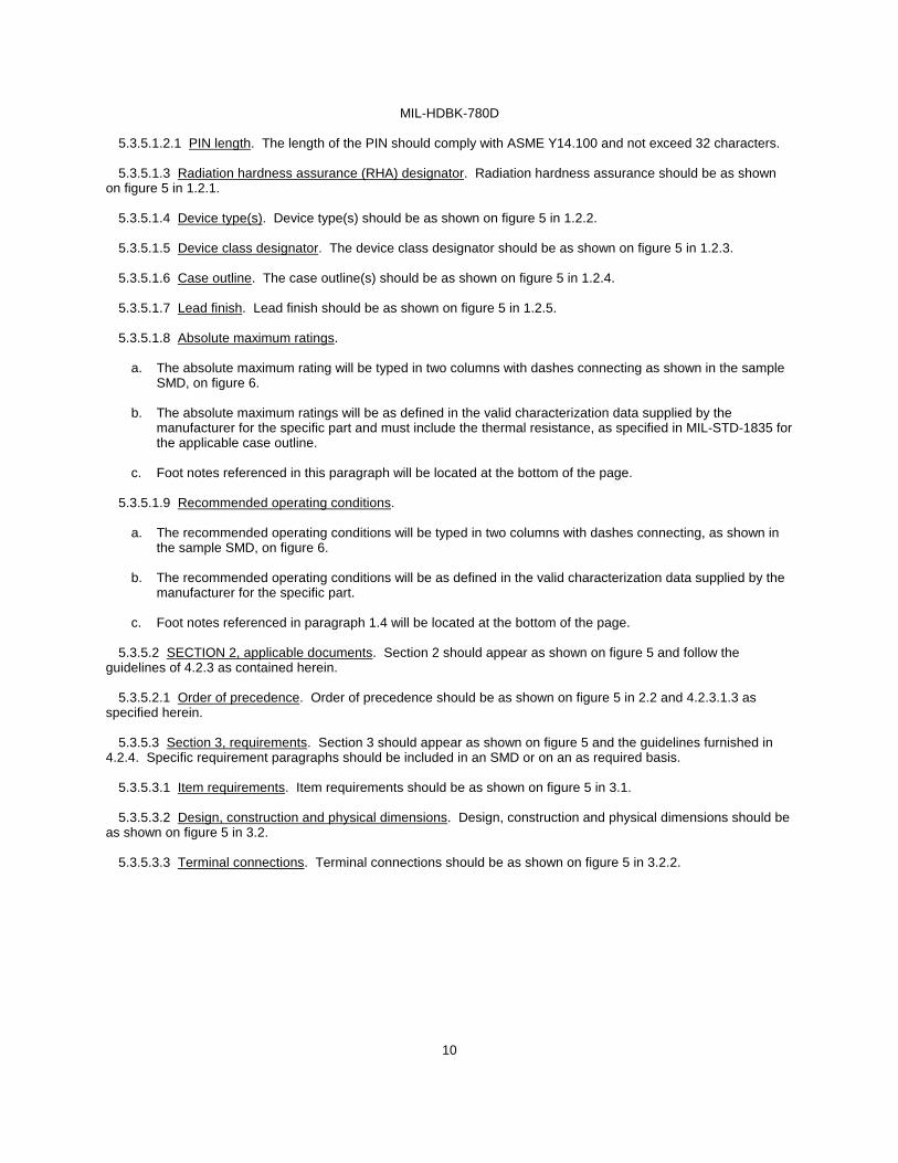
5.3.5.1.2.1 PIN length. The length of the PIN should comply with ASME Y14.100 and not exceed 32 characters.
5.3.5.1.3 Radiation hardness assurance (RHA) designator. Radiation hardness assurance should be as shown
on figure 5 in 1.2.1.
5.3.5.1.4 Device type(s). Device type(s) should be as shown on figure 5 in 1.2.2.
5.3.5.1.5 Device class designator. The device class designator should be as shown on figure 5 in 1.2.3.
5.3.5.1.6 Case outline. The case outline(s) should be as shown on figure 5 in 1.2.4.
5.3.5.1.7 Lead finish. Lead finish should be as shown on figure 5 in 1.2.5.
5.3.5.1.8 Absolute maximum ratings.
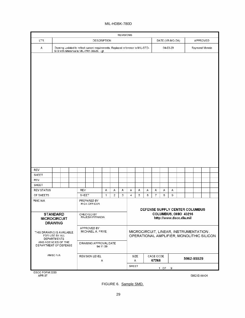
a. The absolute maximum rating will be typed in two columns with dashes connecting as shown in the sample SMD, on figure 6.
b. The absolute maximum ratings will be as defined in the valid characterization data supplied by the
manufacturer for the specific part and must include the thermal resistance, as specified in MIL-STD-1835 for the applicable case outline.
c. Foot notes referenced in this paragraph will be located at the bottom of the page.
5.3.5.1.9 Recommended operating conditions.
a. The recommended operating conditions will be typed in two columns with dashes connecting, as shown in
the sample SMD, on figure 6.
b. The recommended operating conditions will be as defined in the valid characterization data supplied by the manufacturer for the specific part.
c. Foot notes referenced in paragraph 1.4 will be located at the bottom of the page.
5.3.5.2 SECTION 2, applicable documents. Section 2 should appear as shown on figure 5 and follow the
guidelines of 4.2.3 as contained herein.
5.3.5.2.1 Order of precedence. Order of precedence should be as shown on figure 5 in 2.2 and 4.2.3.1.3 as specified herein.
5.3.5.3 Section 3, requirements. Section 3 should appear as shown on figure 5 and the guidelines furnished in 4.2.4. Specific requirement paragraphs should be included in an SMD or on an as required basis.
5.3.5.3.1 Item requirements. Item requirements should be as shown on figure 5 in 3.1.
5.3.5.3.2 Design, construction and physical dimensions. Design, construction and physical dimensions should be as shown on figure 5 in 3.2.
5.3.5.3.3 Terminal connections. Terminal connections should be as shown on figure 5 in 3.2.2.

MIL-HDBK-780D
11
5.3.5.3.4 Block diagram. Although figure 5, 3.2.4 specifies block diagram, this paragraph will be used to
designate block, functional, or logic diagram, as appropriate, for the device being documented.
5.3.5.3.5 Truth tables. Truth tables should appear as on figure 5 in 3.2.3.
5.3.5.3.6 Case outline(s). Case outline(s) should appear as on figure 5 in 3.2.1.
5.3.5.3.7 Electrical performance characteristics and postirradiation parameter limits. Electrical performance characteristics should be as shown on figure 5 in 3.3. Valid characterization data supplied by the manufacture will determine the use of ambient or case operation temperature range.
5.3.5.3.8 Electrical test requirements. Electrical test requirements should be as shown on figure 5 in 3.4.
5.3.5.3.9 Marking. Marking should be as shown on figure 5 in 3.5.
5.3.5.3.10 Tables. Tables e.g., table I, electrical performance characteristics, should be as shown on figure 5. If necessary, a device type column may be added between the Conditions and group A subgroups column to accommodate differences in test conditions and limits, when more than one device type is being specified. Required temperature parameters for each specific part will be typed under the heading Conditions, as shown on figure 5.
5.3.5.3.11 Graphics.
a. Views that are referenced as shown on figure 5 in 3.2, will be located after table 1.
b. All data necessary for terminal connections will be identified in a table format or be drawn as defined in MIL-STD-1835. Refer to sample SMD, figure 6.
c. Whenever two different case outlines are required, an additional page will be added to accommodate the
required data with figure 1 continued.
d. All data necessary for additional views will be drawn as defined in MIL-PRF-38535. Refer to sample SMD, figure 6. Use valid characterization data supplied by the manufacturer for the specific device type.
e. Switching times test circuit and waveforms that are required will be drawn similar in format to that shown on
the sample SMD, figure 6. Use valid characterization data supplied by the manufacturer for the specific device type.
5.3.5.3.12 Certificate of compliance. The certificate of compliance execution should be as shown on figure 5 in
3.6.
5.3.5.3.13 Certificate of conformance. The certificate of conformance should be as shown on figure 5 in 3.7.
5.3.5.3.14 Notification of change. Notification of change should be as shown on figure 5 in 3.8.
5.3.5.3.15 Verification of change. Verification of change should be as shown on figure 5 in 3.9.

MIL-HDBK-780D
12
5.3.6 Section 4, verfication. Section 4 should appear as shown on figure 5 and 4.2.5 as contained herein.
5.3.6.1 Sampling and inspection. Sampling and inspection should be as shown on figure 5 in 4.1.
5.3.6.2 Screening. Screening should be as shown on figure 5 in 4.2. Valid characterization data supplied by the
manufacturer will be used for figure 5, 4.2.1a and 4.2.1b.
5.3.6.3 Qualification inspection. Qualification inspection should be as shown on figure 5 in 4.3. 5.3.6.4 Conformance inspection. Conformance inspection should be as shown on figure 5 in 4.4 and the guidance contained in 4.2.5.4 herein.
5.3.6.4.1 Group A inspection. Additional group A inspection requirements should be as shown on figure 5 in 4.4.1. Valid characterization data supplied by the manufacturer will be used for 4.4.1 subparagraphs (see figure 5).
5.3.6.4.2 Group C inspection. Additional group C inspection requirements should be as shown on figure 5 in 4.4.2. Valid characterization data supplied by the manufacturer will be used for 4.4.2 subparagraphs (see figure 5).
5.3.6.4.3 Group D inspection. Additional group D inspection requirements should be as shown on figure 5 in 4.4.3.
5.3.6.4.4 Group E inspection. Additional group E inspection requirements should be as shown on figure 5 in 4.4.4. Valid characterization data supplied by the manufacturer will be used for 4.4.4 subparagraphs.
5.3.6.5 Tables, electrical tests.
a. The table of electrical test requirements will be formatted as shown on figure 5, table II.
b. The identification of subgroups and tests will be defined in the applicable general specification and valid characterization data supplied by the manufacturer.
c. Any footnote referenced in the table will be located a minimum of two line spaces below the bottom line of
the table.
d. Notes using the term guaranteed will not be included as a part of the preliminary draft, before submittal to the sources of supply.
5.3.7 Section 5, packaging. Section 5 should appear as shown on figure 5 and the guidance indicated in 4.2.6.1
as specified herein.
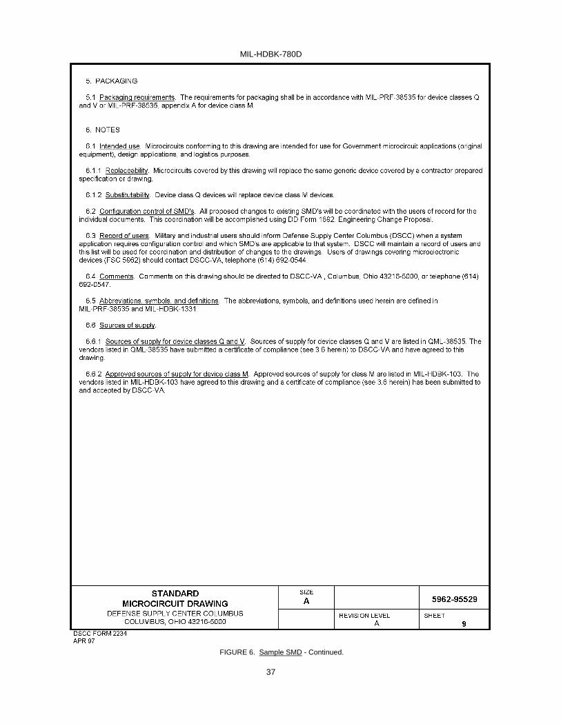
5.3.7.1 Packaging requirements. The packaging requirements should be as shown on figure 5 in 5.1.
5.3.8 Section 6, notes. Section 6 should appear as shown on figure 5 and the guidance in 4.2.7 as specified herein.
5.3.8.1 Intended use. The intended use should be as shown on figure 5 in 6.1 and the guidance in 4.2.7.2 as specified herein.
5.3.8.1.1 Replaceability. The replaceability should be as shown on figure 5 in 6.1.1.

MIL-HDBK-780D
13
5.3.8.1.2 Substitutability. The substitutability should be as shown on figure 5 in 6.1.2.
5.3.8.2 Configuration control of SMD's. The configuration control of SMD's should be as shown on figure 5 in 6.2.
5.3.8.3 Record of users. The record of users should be as shown on figure 5 in 6.3.
5.3.8.4 Comments. The comments should be as shown on figure 5 in 6.4.
5.3.8.5 Abbreviations, symbols, and definitions. The abbreviations, symbols, and definitions should be as shown
on figure 5 in 6.5.
5.3.8.6 Sources of supply. The sources of supply paragraph should be as shown on figure 5 in 6.6.
6. NOTES
6.1 Intended use. The issue of SMD's is intended to minimize the proliferation of duplicate drawings for an item of supply. The use of one drawing for an item of supply within DoD is the objective of the SMD program. SMD's are currently applicable to the acquisition of microcircuits only.
6.1.1 Standard microcircuit drawing program (SMDP). The SMDP is related to the Configuration Management and Parts Management Programs. SMDs are recognized in ASME Y14.100 for application by the DoD for microcircuits compliant with MIL-STD-883. Non-standard microcircuits parts approval is obtained through the procedures of MIL-HDBK-512 and SD-19.
6.2 Draft construction. Communication with the MPCAG point of contact for the purpose of draft SMD construction will usually be through use of computer or word processor. Defense Supply Center Columbus, DSCC-VA , should be contacted concerning system capability, and modem and telecommunication compatibility (see figure 4).
6.3 Certificate of compliance. A Certificate of Compliance (C of C ) is a document by which an authorized official of the microcircuit manufacturer certifies that the microcircuit being supplied in accordance with the applicable SMD by the vendor meets the Item Requirements as stated therein. The C of C is delivered by the vendor to the MPCAG with the final SMD.
6.4 Subject term (key word) listing.
Certificate of compliance Military parts control advisory group Parts Management program Standard microcircuit drawing Qualified manufacturers list 6.5 Changes from previous issue. Marginal notations are not used in this revision to identify changes with respect
to the previous issue due to the extent of the changes.

MIL-HDBK-780D
14
FIGURE 1. Drawing, title sheet.

MIL-HDBK-780D
15
FIGURE 2. Drawing, continuation sheet.
MIL-HDBK-780D
16
Figure 3. Certificate of compliance.

MIL-HDBK-780D
17
FIGURE 3. Certificate of compliance. - Continued.

MIL-HDBK-780D
18
FIGURE 3. Certificate of compliance. - Continued.

MIL-HDBK-780D
19
SMD PREPARATION FLOWCHART DSCC DETERMINES YES IF NEW SMD NO REQUIRED (Continued) FIGURE 4. SMD preparation flowchart.
CONTRACTOR SUBMITS 5962 PART REQUEST TO MPCAG
MPCAG REVIEWS REQUEST
MPCAG RETURN EVALUATION ASSIGNS SMD NUMBER, AND REQUESTS PREPARATION OF
SMD THROUGH PROGRAM OFFICE TO CONTRACTOR
CONTRACTOR UTILIZES EXISTING
SMD
CONTRACTOR PREPARES PRELIMINARY DRAFT
CONTRACTOR SUBMITS PRELIMINARY DRAFT
TO MPCAG AND PROGRAM OFFICE
MPCAG REVIEWS PRELIMINARY DRAFT AND PROVIDES
RECOMMENDED CHANGES

MIL-HDBK-780D
20
FIGURE 4. SMD preparation flowchart - Continued.
CONTRACTOR PROGRAM OFFICE AND MPCAG RESOLVE COMMENTS
CONTRACTOR INCORPORATES CHANGES
CONTRACTOR RETURNS REVISED DRAFT PACKAGE TO MPCAG
MPCAG SUBMITS TO DEVICE MANUFACTURER
DEVICE MANUFACTURER SENDS COMMENTS REGARDING DRAFT AND COPIES TO MPCAG
MPCAG, PROGRAM OFFICE, CONTRACTOR AND DEVICE MANUFACTURER
RESOLVE COMMENTS AND DEVICE MANUFACTURER FORWARDS
SIGNED C OF C TO MPCAG
MPCAG PREPARES, APPROVES DATES FINAL SMD
ADVANCE COPIES SENT TO CONTRACTOR PROGRAM OFFICE AND DEVICE
MANUFACTURER
SMD IS REPRODUCED AND DISTRIBUTED
BY MPCAG

MIL-HDBK-780D
21
FIGURE 5. SMD with boilerplate.

MIL-HDBK-780D
22
FIGURE 5. SMD with boilerplate - Continued.
MIL-HDBK-780D
23
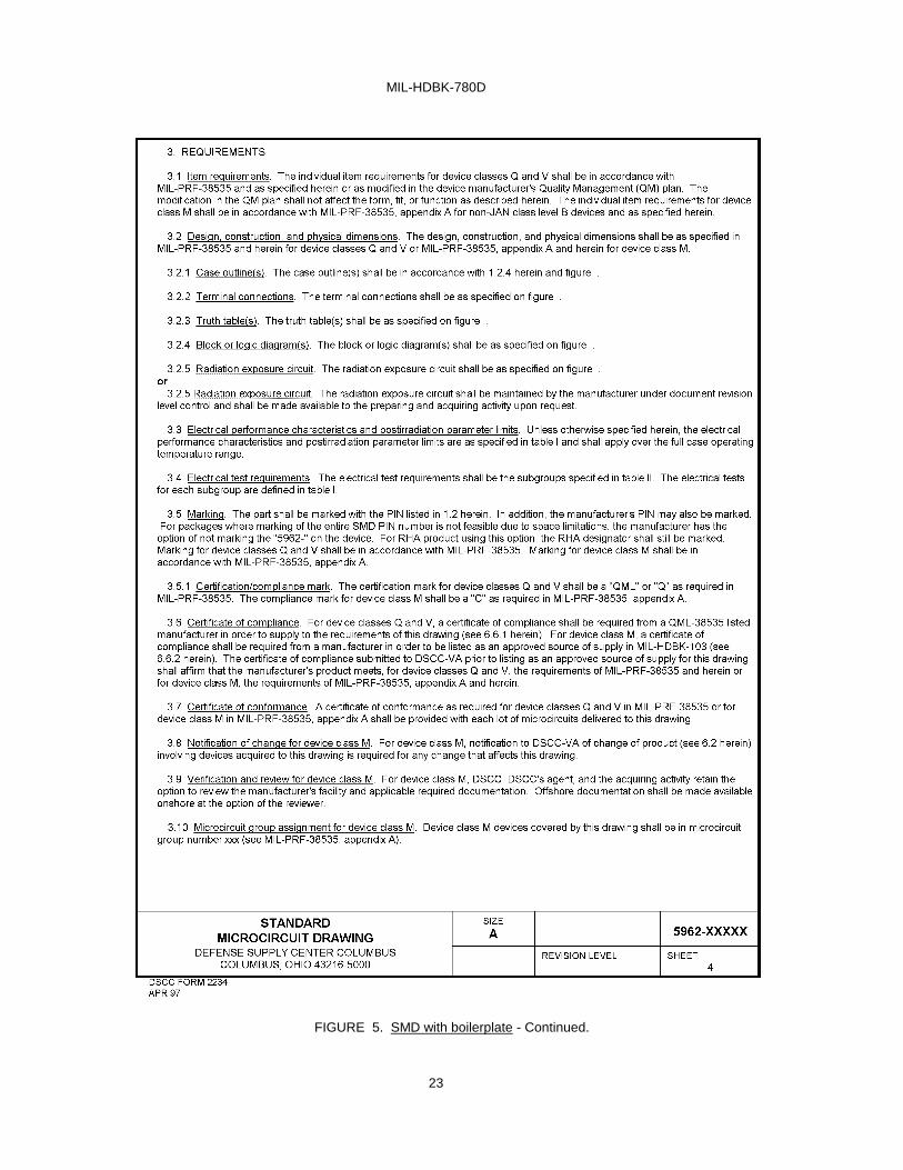
FIGURE 5. SMD with boilerplate - Continued.

MIL-HDBK-780D
24
FIGURE 5. SMD with boilerplate - Continued.

MIL-HDBK-780D
25
FIGURE 5. SMD with boilerplate - Continued.

MIL-HDBK-780D
26
FIGURE 5. SMD with boilerplate - Continued.

MIL-HDBK-780D
27
FIGURE 5. SMD with boilerplate - Continued.

MIL-HDBK-780D
28
FIGURE 5. SMD with boilerplate - Continued.
MIL-HDBK-780D
29
FIGURE 6. Sample SMD.

MIL-HDBK-780D
30
FIGURE 6. Sample SMD - Continued.

MIL-HDBK-780D
31
FIGURE 6. Sample SMD - Continued.

MIL-HDBK-780D
32
FIGURE 6. Sample SMD - Continued.

MIL-HDBK-780D
33
FIGURE 6. Sample SMD - Continued.

MIL-HDBK-780D
34
FIGURE 6. Sample SMD - Continued.

MIL-HDBK-780D
35
FIGURE 6. Sample SMD - Continued.

MIL-HDBK-780D
36
FIGURE 6. Sample SMD - Continued.
MIL-HDBK-780D
37
FIGURE 6. Sample SMD - Continued.

MIL-HDBK-780D
38
FIGURE 6. Sample SMD - Continued.

MIL-HDBK-780D
39
Custodians: Preparing activity: Army - CR DLA-CC Navy - EC Air Force - 11 DLA-CC
Review activities:
Army - AR, MI, SM (Project 5962-1956) Navy - AS, CG, MC, SH, TD Air Force - 03, 19, 99
NOTE: The activities listed above were interested in this document as of the date of this document. Since organizations and responsibilities can change, you should verify the currency of the information above using the ASSIST Online database at www.dodssp.daps.mil.